EP2635014A2 - System zur Bereitstellung von Vorrichtungsinformationen zur Bereitstellung von Informationen über eine in allen elektronischen Hauptvorrichtungen und einer elektronischen Untervorrichtung enthaltene Website - Google Patents
System zur Bereitstellung von Vorrichtungsinformationen zur Bereitstellung von Informationen über eine in allen elektronischen Hauptvorrichtungen und einer elektronischen Untervorrichtung enthaltene Website Download PDFInfo
- Publication number
- EP2635014A2 EP2635014A2 EP13157068.1A EP13157068A EP2635014A2 EP 2635014 A2 EP2635014 A2 EP 2635014A2 EP 13157068 A EP13157068 A EP 13157068A EP 2635014 A2 EP2635014 A2 EP 2635014A2
- Authority
- EP
- European Patent Office
- Prior art keywords
- sub
- main
- connection
- option
- nic
- Prior art date
- Legal status (The legal status is an assumption and is not a legal conclusion. Google has not performed a legal analysis and makes no representation as to the accuracy of the status listed.)
- Granted
Links
Images






Classifications
-
- H—ELECTRICITY
- H04—ELECTRIC COMMUNICATION TECHNIQUE
- H04N—PICTORIAL COMMUNICATION, e.g. TELEVISION
- H04N1/00—Scanning, transmission or reproduction of documents or the like, e.g. facsimile transmission; Details thereof
- H04N1/00127—Connection or combination of a still picture apparatus with another apparatus, e.g. for storage, processing or transmission of still picture signals or of information associated with a still picture
- H04N1/00204—Connection or combination of a still picture apparatus with another apparatus, e.g. for storage, processing or transmission of still picture signals or of information associated with a still picture with a digital computer or a digital computer system, e.g. an internet server
- H04N1/00209—Transmitting or receiving image data, e.g. facsimile data, via a computer, e.g. using e-mail, a computer network, the internet, I-fax
- H04N1/00222—Transmitting or receiving image data, e.g. facsimile data, via a computer, e.g. using e-mail, a computer network, the internet, I-fax details of image data generation or reproduction, e.g. scan-to-email or network printing
-
- G—PHYSICS
- G06—COMPUTING OR CALCULATING; COUNTING
- G06F—ELECTRIC DIGITAL DATA PROCESSING
- G06F3/00—Input arrangements for transferring data to be processed into a form capable of being handled by the computer; Output arrangements for transferring data from processing unit to output unit, e.g. interface arrangements
- G06F3/12—Digital output to print unit, e.g. line printer, chain printer
- G06F3/1201—Dedicated interfaces to print systems
- G06F3/1278—Dedicated interfaces to print systems specifically adapted to adopt a particular infrastructure
- G06F3/1285—Remote printer device, e.g. being remote from client or server
- G06F3/1287—Remote printer device, e.g. being remote from client or server via internet
-
- H—ELECTRICITY
- H04—ELECTRIC COMMUNICATION TECHNIQUE
- H04N—PICTORIAL COMMUNICATION, e.g. TELEVISION
- H04N1/00—Scanning, transmission or reproduction of documents or the like, e.g. facsimile transmission; Details thereof
- H04N1/0035—User-machine interface; Control console
- H04N1/00405—Output means
- H04N1/00408—Display of information to the user, e.g. menus
- H04N1/00464—Display of information to the user, e.g. menus using browsers, i.e. interfaces based on mark-up languages
-
- H—ELECTRICITY
- H04—ELECTRIC COMMUNICATION TECHNIQUE
- H04N—PICTORIAL COMMUNICATION, e.g. TELEVISION
- H04N2201/00—Indexing scheme relating to scanning, transmission or reproduction of documents or the like, and to details thereof
- H04N2201/0077—Types of the still picture apparatus
- H04N2201/0094—Multifunctional device, i.e. a device capable of all of reading, reproducing, copying, facsimile transception, file transception
Definitions
- the present disclosure relates to a device information providing system for providing information through a Web page included in each of a main electronic device and a sub-electronic device.
- a typical device information providing system includes a network card unit and a printing unit that are connected to each other.
- the network card unit includes a network I/F unit for communicating with a host computer, a printing device I/F unit for communicating with the printing unit, a device-independent content unit for providing Web content of the network card unit, and a WWW server unit for controlling communications.
- the printing unit includes a network card I/F unit for communicating with the printing device I/F unit and a device-dependent content unit for providing Web content of the printing unit.
- the WWW server unit passes the Web content to the host computer from the device-independent content unit or the device-dependent content unit in response to a request received from the host computer while a connection is established with respect to the host computer via the network I/F unit.
- the network card unit which includes a Web server that has established a connection with respect to an information processing device, acquires the Web content of the printing unit. Accordingly, if there is a change in a combination of the network card unit and the printing unit due to a model change or a change in product specifications, the network card unit may fail to acquire the Web content of the printing unit.
- a device information providing system includes a main electronic device and a sub-electronic device.
- the main electronic device includes a main-side external communication unit, a main-side inter-device communication unit, a main-side HTTP server, and a main-side communication control unit.
- the main-side external communication unit is configured to communicate with an information processing device.
- the main-side HTTP server is configured to provide a main-side page including a Web page of the main electronic device.
- the main-side communication control unit is configured to: (i) disconnect a main-side normal connection between the information processing device and the main-side HTTP server via the main-side external communication unit when a connection to a sub-side switching URL is requested by the information processing device while the main-side normal connection is established, (ii) and establish a main-side transfer connection between the information processing device and a sub-side HTTP server via the main-side external communication unit, the main-side inter-device communication unit, and a sub-side inter-device communication unit.
- the sub-electronic device is connected to the main electronic device, and includes the sub-side inter-device communication unit and the sub-side HTTP server.
- the sub-side inter-device communication unit is configured to communicate with the main-side inter-device communication unit.
- the sub-side HTTP server is configured to provide a sub-side page to which the sub-side switching URL used to switch the connection is assigned, the sub-side page comprising a Web page of the sub-electronic device.
- the main-side inter-device communication unit is configured to communicate with the sub-electronic device.
- An electronic device includes a main-side external communication unit, a main-side inter-device communication unit, a main-side HTTP server, a main-side communication control unit, and an interface.
- the main-side external communication unit is configured to communicate with an information processing device.
- the main-side inter-device communication unit is configured to communicate with a sub-electronic device.
- the main-side HTTP server is configured to provide a main-side page including a Web page of the electronic device.
- the main-side communication control unit is configured to: (i) disconnect a main-side normal connection that is a connection between the information processing device and the main-side HTTP server via the main-side external communication unit when a connection to a sub-side switching URL is requested by the information processing device while the main-side normal connection is established, and (ii) establish a main-side transfer connection that is a connection between the information processing device and a sub-side HTTP server via the main-side external communication unit, the main-side inter-device communication unit, and a sub-side inter-device communication unit.
- the interface is configured to be connected to the sub-electronic device including the sub-side inter-device communication unit configured to communicate with the main-side inter-device communication unit and the sub-side HTTP server configured to provide a sub-side page to which the sub-side switching URL used to switch the connection is assigned, the sub-side page including a Web page of the sub-electronic device.
- FIG. 1 illustrates a configuration of a network system, according to an embodiment of the present disclosure
- FIG. 2 illustrates a configuration of an MFP main body, according to an embodiment of the present disclosure
- FIG. 3 illustrates a configuration of an Option NIC, according to an embodiment of the present disclosure
- FIG. 4 illustrates a configuration of a PC, according to the embodiment of the present disclosure
- FIG. 5 illustrates an example operation of the network system of FIG. 1 performed to establish an MFP main body-side normal connection, according to an embodiment of the present disclosure
- FIG. 6 illustrates a flow of information within an MFP obtained while the MFP main body-side normal connection is established, according to an embodiment of the present disclosure
- FIG. 7 illustrates an example flow for switching a request transfer destination performed when the MFP main body-side normal connection is established, according to an embodiment of the present disclosure
- FIG. 8 illustrates an example of an MFP main body setting Web page, according to an embodiment of the present disclosure
- FIG. 9 illustrates an example operation of the network system of FIG. 1 performed to switch from the MFP main body-side normal connection to an MFP main body-side transfer connection, according to an embodiment of the present disclosure
- FIG. 10 illustrates a flow of information within the MFP obtained while the MFP main body-side transfer connection is established, according to an embodiment of the present disclosure
- FIG. 11 illustrates an example of a Web page for Option NIC setting, according to an embodiment of the present disclosure
- FIG. 12 illustrates an example operation of the network system of FIG. 1 performed to switch from the MFP main body-side transfer connection to the MFP main body-side normal connection, according to an embodiment of the present disclosure
- FIG. 13 illustrates an example of operation of the network system of FIG. 1 performed to establish an Option NIC-side normal connection, according to an embodiment of the present disclosure
- FIG. 14 illustrates a flow of information within the MFP obtained while the Option NIC-side normal connection is established, according to an embodiment of the present disclosure
- FIG. 15 illustrates an example flow for switching the request transfer destination performed when the Option NIC-side normal connection is established, according to an embodiment of the present disclosure
- FIG. 16 illustrates an example operation of the network system of FIG. 1 performed to switch from the Option NIC-side normal connection to an Option NIC-side transfer connection, according to an embodiment of the present disclosure
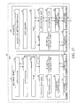
- FIG. 17 illustrates a flow of information within the MFP obtained while the Option NIC-side transfer connection is established, according to an embodiment of the present disclosure.
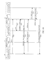
- FIG. 18 illustrates an example operation of the network system of FIG. 1 performed to switch from the Option NIC-side transfer connection to the Option NIC-side normal connection, according to an embodiment of the present disclosure.
- FIG. 1 illustrates an example configuration of a network system according to an embodiment of the present disclosure.
- network system 10 includes multifunction peripheral (MFP) 20 and personal computer (PC) 90, an information processing device external to MFP 20.
- MFP multifunction peripheral
- PC personal computer
- MFP 20 includes MFP main body 30 that serves as an image forming apparatus and an option network interface card (Option NIC) 60.
- Option NIC 60 is a network interface card detachably attachable to MFP main body 30.
- MFP main body 30 and Option NIC 60 are connected to each other.
- MFP 20 and PC 90 are communicably connected to each other via network 11 such as a local area network (LAN).
- network 11 such as a local area network (LAN).
- FIG. 2 illustrates a configuration of the MFP main body according to the embodiment of the present disclosure.
- MFP main body 30 includes an operation unit 31 that may include input devices such as buttons through which various operations may be input by a user, display unit 32 that may include a display device such as a liquid crystal display (LCD) for displaying various kinds of information, printer 33 that may include a printing device for executing printing of an image on a recording medium such as paper, scanner 34 that may include a reading device for reading an image from an original, FAX communication unit 35 including a FAX device for performing FAX communications through a communication line such as a public telephone line, network communication unit 36 that may include a communication device for performing communications through network 11, internal communication I/F 37 serving as an inter-device communication unit for communicating with Option NIC 60, storage unit 40 that may include a storage device such as an electrically erasable programmable read only memory (EEPROM) or a hard disk drive (HDD) for storing different kinds of data, and control unit 50 for controlling an entirety of MFP main body 30.
- EEPROM electrically erasable programmable read only memory
- HDD hard
- Network communication unit 36 may be an external communication unit for communicating with a PC, and may, for example, be used for wired communications.
- Storage unit 40 stores application program 41 for generating a Web page for a setting menu (hereinafter referred to as "MFP main body setting Web page") necessary to set different functions of MFP main body 30, HTTP server program 42 used as a hypertext transfer protocol (HTTP) server for providing the MFP main body setting Web page, and device information providing program 43 for providing device information.
- MFP main body setting Web page a setting menu
- HTTP server program 42 used as a hypertext transfer protocol (HTTP) server for providing the MFP main body setting Web page
- device information providing program 43 for providing device information.
- the MFP main body setting Web page includes a Web page for setting of MFP main body 30.
- An MFP main body-side normal URL accessed via network communication unit 36 and an MFP main body-side switching URL used to switch the connection are assigned to the MFP main body setting Web page.
- the MFP main body-side normal URL and the MFP main body-side switching URL may be, for example, "http://mfp_ip/"and"http://mfp_ip/mfp", respectively. Note that "mfp_ip" indicates an IP address of MFP main body 30.
- Application program 41, HTTP server program 42, and device information providing program 43 may be installed in MFP main body 30 at a manufacturing stage of MFP main body 30, installed in MFP main body 30 from a storage medium such as a universal serial bus (USB) memory or an SD memory card, or may be installed in MFP main body 30 from network 11.
- a storage medium such as a universal serial bus (USB) memory or an SD memory card
- Control unit 50 may include, for example, a central processing unit (CPU), a read only memory (ROM) for storing a program and different kinds of data, and a random access memory (RAM) used as a work area for the CPU (none of which are shown in Figure 2 ).
- the CPU is configured to execute the program stored in the ROM or storage unit 40.
- Control unit 50 executes application program 41 stored in storage unit 40, thereby functioning as application 51 for generating the MFP main body setting Web page.
- control unit 50 executes HTTP server program 42 stored in storage unit 40, thereby functioning as HTTP server 52 for providing the MFP main body setting Web page.
- control unit 50 executes device information providing program 43 stored in storage unit 40, thereby functioning as hypertext transfer protocol daemon (httpd) 53 that serves as a communication control unit.
- Httpd 53 can switch between (i) an MFP main body-side normal connection, between the PC and HTTP server 52, via network communication unit 36 and (ii) an MFP main body-side transfer connection, between the PC and an HTTP server of an Option NIC (described later), via network communication unit 36, internal communication I/F 37, and internal communication I/F 62 of Option NIC 60.
- control unit 50 executes the program stored in storage unit 40, thereby functioning as TCP control unit 54 for controlling transmission control protocol (TCP) communications, IP control unit 55 for controlling Internet protocol (IP) communications, Ethernet control unit 56 for controlling Ethernet® communications, and internal communication control unit 57 for controlling communications performed by internal communication I/F 37.
- TCP transmission control protocol
- IP Internet protocol
- Ethernet control unit 56 for controlling Ethernet® communications
- internal communication control unit 57 for controlling communications performed by internal communication I/F 37.
- FIG. 3 illustrates a configuration of the Option NIC according to the embodiment of the present disclosure.
- Option NIC 60 includes network communication unit 61 that may include a network communication device for performing communications through network 11, internal communication I/F 62 for communicating with an internal communication I/F of the MFP main body, storage unit 70 that may include a storage device such as an EEPROM for storing different kinds of data, and control unit 80 for controlling Option NIC 60.
- network communication unit 61 may include a network communication device for performing communications through network 11
- internal communication I/F 62 for communicating with an internal communication I/F of the MFP main body
- storage unit 70 that may include a storage device such as an EEPROM for storing different kinds of data
- control unit 80 for controlling Option NIC 60.
- Network communication unit 61 may be an external communication unit for communicating with PC 90, and may be used for wireless communications.
- Storage unit 70 stores Option NIC setting Web page 71 including a Web page for a setting menu necessary to set different functions of Option NIC 60 such as a print server function, HTTP server program 72 that may include a program for the HTTP server for providing Option NIC setting Web page 71, and device information providing program 73 for providing device information.
- Option NIC setting Web page 71 including a Web page for a setting menu necessary to set different functions of Option NIC 60 such as a print server function
- HTTP server program 72 that may include a program for the HTTP server for providing Option NIC setting Web page 71
- device information providing program 73 for providing device information.
- Option NIC setting Web page 71 includes a Web page for network setting of Option NIC 60.
- An Option NIC-side normal URL accessed via network communication unit 61 and an Option NIC-side switching URL used to switch the connection are assigned to Option NIC setting Web page 71.
- the Option NIC-side normal URL and the Option NIC-side switching URL are, for example, "http://option_nic_ip/” and "http://option_nic_ip/option_nic", respectively. Note that "option_nic_ip" indicates an IP address of Option NIC 60.
- HTTP server program 72 and device information providing program 73 may be installed in Option NIC 60 at a manufacturing stage of Option NIC 60 or installed in Option NIC 60 from network 11.
- Control unit 80 includes, for example, a CPU, a ROM for storing a program and different kinds of data, and a RAM used as a work area for the CPU (none of which are shown in Figure 3 ).
- the CPU is configured to execute the program stored in the ROM or storage unit 70.
- Control unit 80 executes HTTP server program 72 stored in storage unit 70, thereby functioning as HTTP server 81 forproviding Option NIC setting Web page 71.
- control unit 80 executes device information providing program 73 stored in storage unit 70, thereby functioning as httpd 82 that serves as a communication control unit.
- Httpd 82 can switch between (i) an Option NIC-side normal connection, between PC 90 and HTTP server 81, via network communication unit 61 and (ii) an Option NIC-side transfer connection, between PC 90 and the HTTP server of the MFP main body, via network communication unit 61, internal communication I/F 62, and internal communication I/F 37 of MFP main body 30.
- control unit 80 executes the program stored in storage unit 70, thereby functioning as TCP control unit 83 for controlling TCP communications, IP control unit 84 for controlling IP communications, Ethernet control unit 85 for controlling Ethernet® communications, and internal communication control unit 86 for controlling communications performed by internal communication I/F 62.
- FIG. 4 illustrates a configuration of the PC according to the embodiment of the present disclosure.
- PC 90 includes operation unit 91 that may include input devices such as a mouse and a keyboard through which various operations may be input by a user, display unit 92 that may include a display device such as an LCD for displaying various kinds of information, network communication unit 93 that may include a network communication device for performing communications through network 11, storage unit 100 that may include a storage device such as an HDD for storing different kinds of data, and control unit 110 for controlling PC 90.
- input devices such as a mouse and a keyboard through which various operations may be input by a user
- display unit 92 that may include a display device such as an LCD for displaying various kinds of information
- network communication unit 93 that may include a network communication device for performing communications through network 11
- storage unit 100 that may include a storage device such as an HDD for storing different kinds of data
- control unit 110 for controlling PC 90.
- Storage unit 100 stores printer driver 101 for controlling printing performed on MFP 20 and Web browser program 102 used for a Web browser for browsing Web pages.
- Printer driver 101 and Web browser program 102 may be installed in PC 90 at a manufacturing stage of PC 90, installed in PC 90 from a storage medium such as a USB memory, a compact disc (CD), or a digital versatile disc (DVD), or installed in PC 90 from network 11.
- a storage medium such as a USB memory, a compact disc (CD), or a digital versatile disc (DVD), or installed in PC 90 from network 11.
- Control unit 110 includes, for example, a CPU, a ROM for storing a program and different kinds of data, and a RAM used as a work area for the CPU (none of which are shown in Figure 4 ).
- the CPU is configured to execute the program stored in the ROM or storage unit 100.
- Control unit 110 executes Web browser program 102 stored in storage unit 100, thereby functioning as Web browser 111 for browsing Web pages.
- FIG. 5 illustrates an example operation of network system 10 performed to establish the MFP main body-side normal connection.
- the example of FIG. 5 relates to the operation of network system 10 performed when a user inputs the IP address of MFP main body 30 to the Web browser through an operation unit of PC 90.
- Web browser 111 If the user activates Web browser 111 through operation unit 91 of PC 90 and inputs the IP address "mfp_ip" of MFP main body 30 to Web browser 111, Web browser 111 transmits a GET request to "http://mfp_ip/" (S201).
- FIG. 6 illustrates a flow of information within the MFP obtained while the MFP main body-side normal connection is established.
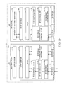
- the GET request is received by the network communication unit of MFP main body 30 corresponding to the IP address "mfp_ip". As illustrated in FIG. 6 , the GET request is transferred to httpd 53 via Ethernet control unit 56, IP control unit 55, and TCP control unit 54, sequentially. Httpd 53 of MFP main body 30 determines a transfer destination of the GET request, as illustrated in FIG. 7 , based on a URL of the GET request transferred from TCP control unit 54.
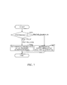
- FIG. 7 illustrates an example flow of switching processing of a request transfer destination performed when the MFP main body-side normal connection is established.
- the example flow of FIG. 7 relates to the switching processing of the request transfer destination performed by an httpd of the MFP main body.
- httpd 53 of MFP main body 30 confirms the URL of the GET request (S291), and because the confirmed URL is "http://mfp_ip/", the transfer destination of the GET request is determined as the HTTP server of MFP main body 30 (S292).
- httpd 53 of MFP main body 30 determines the transfer destination of the GET request as HTTP server 52, and then transfers the GET request to HTTP server 52 (S202).
- HTTP server 52 acquires the MFP main body setting Web page corresponding to the GET request from the application of the MFP main body, and passes the acquired MFP main body setting Web page to httpd 53 (S203) thereby establishing the MFP main body-side normal connection.
- httpd 53 sends the MFP main body setting Web page passed from HTTP server 52 to Web browser 111 (S204).
- the MFP main body setting Web page is finally received by the Web browser of the PC via httpd 53, TCP control unit 54, IP control unit 55, Ethernet control unit 56, and network communication unit 36, sequentially.
- FIG. 8 illustrates an example of the MFP main body setting Web page.
- the MFP main body setting Web page exemplified in FIG. 8 is displayed on a display unit of the PC by the Web browser.
- the MFP main body setting Web page illustrated in FIG. 8 includes display area 301 for displaying different kinds of information on the MFP main body, plurality of setting buttons 302 used to display Web pages for different kinds of settings of the MFP main body, and connection destination switching button 303 for switching a connection destination of the Web browser. Accordingly, while the MFP main body-side normal connection is established, the user can confirm different kinds of information on the MFP main body and execute different kinds of settings of the MFP main body through the MFP main body setting Web page. For example, through setting buttons 302, the user can change network settings of the MFP main body such as changing the media access control (MAC) address filtering settings, IP filtering settings, or security architecture for Internet protocol (IPsec) settings.
- MAC media access control
- IPsec Internet protocol
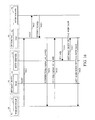
- FIG. 9 illustrates an example operation of network system 10 performed to switch from the MFP main body-side normal connection to MFP main body-side transfer connection.
- the example of FIG. 9 relates to the operation of network system 10 performed when the user depresses a connection destination switching button, such as connection destination switching button 303, of the MFP main body setting Web page through the operation unit of PC 90 while the MFP main body-side normal connection is established.
- a connection destination switching button such as connection destination switching button 303
- Web browser 111 transmits a POST request indicating that the connection destination switching button has been depressed to "http://mfp_ip/" (S221).
- the POST request is transferred to httpd 53 via Ethernet control unit 56, IP control unit 55, and TCP control unit 54, sequentially.
- Httpd 53 determines a transfer destination of the POST request based on a URL of the POST request transferred from TCP control unit 54.
- httpd 53 of MFP main body 30 confirms the URL of the POST request (S291), and because the confirmed URL is "http://mfp_ip/", the transfer destination of the POST request is determined as the HTTP server of MFP main body 30 (S292).
- httpd 53 determines the transfer destination of the POST request as HTTP server 52, and then transfers the POST request to HTTP server 52 (S222).
- HTTP server 52 passes a redirection destination URL "/option_nic" to httpd 53 in response to the POST request indicating that the connection destination switching button has been depressed (S223).
- httpd 53 sends the redirection destination URL "http://mfp_ip/option_nic" passed from HTTP server 52 to Web browser 111 (S224).
- the MFP is allowed to easily switch from the MFP main body-side normal connection to the MFP main body-side transfer connection based on the Option NIC-side switching URL of which the PC 90 has been notified by MFP main body 30.
- the redirection destination URL "http://mfp_ip/option_nic" is received by Web browser 111 via httpd 53, TCP control unit 54, IP control unit 55, Ethernet control unit 56, and the network communication unit 36, sequentially.
- httpd 53 notifies the PC of the Option NIC-side switching URL "http://mfp_ip/option_nic" in response to the POST request which indicates that the connection destination switching button has been depressed and which has been received from the PC.
- the Web browser 111 transmits the GET request to the received redirection destination URL "http://mfp_ip/option_nic" (S225).
- PC 90 requests httpd 53 for a connection to "http://mfp_ip/option_nic" serving as the Option NIC-side switching URL.
- FIG. 10 illustrates a flow of information within the MFP obtained while the MFP main body-side transfer connection is established.
- the GET request is transferred to httpd 53 via Ethernet control unit 56, IP control unit 55, and TCP control unit 54, sequentially.
- Httpd 53 determines a transfer destination of the GET request, as illustrated in FIG. 7 , based on a URL of the GET request transferred from TCP control unit 54.
- the httpd of the MFP main body confirms the URL of the GET request (S291), and because the confirmed URL is "http://mfp_ip/option_nic", the transfer destination of the GET request is determined as the Option NIC (S293).
- httpd 53 determines the transfer destination of the GET request to be Option NIC 60
- httpd 53 disconnects the MFP main body-side normal connection and then transfers the GET request to Option NIC 60 (S226).
- the GET request is transferred to HTTP server 81 of Option NIC 60 via internal communication control unit 57, internal communication I/F 37, internal communication I/F 62, and internal communication control unit 86, sequentially.
- HTTP server 81 acquires an Option NIC setting Web page corresponding to the GET request from Option NIC setting Web page 71, and sends the acquired Option NIC setting Web page to httpd 53 as illustrated in FIG. 9 (S227).
- the Option NIC setting Web page is received by httpd 53 via server 81, internal communication control unit 86, internal communication I/F 62, internal communication I/F 37, and internal communication control unit 57, sequentially.
- httpd 53 establishes the MFP main body-side transfer connection.
- httpd 53 sends the Option NIC setting Web page passed from HTTP server 81 to Web browser 111 (S228).
- the Option NIC setting Web page is finally received by Web browser 111 via httpd 53, TCP control unit 54, IP control unit 55, Ethernet control unit 56, and network communication unit 36, sequentially.
- the MFP can cause the HTTP server of Option NIC 60 to provide the Option NIC setting Web page to the PC by establishing the connection between the PC and the HTTP server of the Option NIC via the MFP main body.
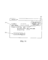
- FIG. 11 illustrates an example of the Option NIC setting Web page.
- the Option NIC setting Web page exemplified in FIG. 11 is displayed on display unit 92 of the PC 90 by Web browser 111.
- the Option NIC setting Web page illustrated in FIG. 11 includes display area 321 for displaying different kinds of information on the Option NIC, setting button 322 used to display a Web page for different kinds of settings of the Option NIC, and connection destination switching button 323 for switching a connection destination of the Web browser.
- the user can confirm different kinds of information on the Option NIC and execute different kinds of settings of the Option NIC through the Option NIC setting Web page.
- the user can change network settings of the Option NIC such as changing MAC address filtering settings, IP filtering settings, and IPsec settings.
- FIG. 12 illustrates an example operation of network system 10 switching from the MFP main body-side transfer connection to the MFP main body-side normal connection.
- the example of FIG. 12 relates to the operation of network system 10 performed when a user depresses a connection destination switching button, such as connection destination switching button 323, of the Option NIC setting Web page through the operation unit of PC 90 while the MFP main body-side transfer connection is established.
- a connection destination switching button such as connection destination switching button 323, of the Option NIC setting Web page through the operation unit of PC 90 while the MFP main body-side transfer connection is established.
- Web browser 111 transmits a POST request indicating that the connection destination switching button has been depressed to "http://mfp_ip/option_nic" (S241).
- the POST request is transferred to httpd 53 via Ethernet control unit 56, IP control unit 55, and TCP control unit 54, sequentially.
- Httpd 53 determines a transfer destination of the POST request based on a URL of the POST request transferred from TCP control unit 54.
- httpd 53 of MFP main body 30 confirms the URL of the POST request (S291), and because the confirmed URL is "http://mfp_ip/option_nic", the transfer destination of the POST request is determined as the Option NIC (S293).
- httpd 53 determines the transfer destination of the POST request as Option NIC 60, and then transfers the POST request to Option NIC 60 (S242).
- the POST request is transferred to the HTTP server 81 of Option NIC 60 via internal communication control unit 57, internal communication I/F 37, internal communication I/F 62, and internal communication control unit 86, sequentially.
- the HTTP server 81 passes a redirection destination URL "/mfp" to httpd 53 in response to the POST request indicating that the connection destination switching button has been depressed (S243).
- the redirection destination URL "/mfp" is received by httpd 53 via HTTP server 81, internal communication control unit 86, internal communication I/F 62, internal communication I/F 37, and internal communication control unit 57, sequentially.
- httpd 53 sends the redirection destination URL "http://mfp_ip/mfp" passed from the HTTP server 81 to Web browser 111 (S244).
- redirection destination URL "http://mfp_ip/mfp" is finally received by the Web browser via httpd 53, TCP control unit 54, IP control unit 55, Ethernet control unit 56, and network communication unit 36, sequentially.
- httpd 53 notifies the PC of the MFP main body-side switching URL "http://mfp_ip/mfp" in response to the POST request which indicates that the connection destination switching button has been depressed and which has been received from the PC.
- Web browser 111 transmits the GET request to the received redirection destination URL "http://mfp_ip/mfp" (S245).
- PC 90 requests httpd 53 for a connection to "http://mfp_ip/mfp" serving as the MFP main body-side switching URL.
- the MFP is allowed to easily switch from the MFP main body-side transfer connection to the MFP main body-side normal connection.
- the GET request is transferred to httpd 53 via Ethernet control unit 56, IP control unit 55, and TCP control unit 54, sequentially.
- Httpd 53 determines a transfer destination of the GET request based on a URL of the GET request transferred from TCP control unit 54.
- httpd 53 of MFP main body 30 confirms the URL of the GET request (S291), and because the confirmed URL is "http://mfp_ip/mfp", the transfer destination of the GET request is determined as HTTP server 52 (S292).
- httpd 53 determines the transfer destination of the GET request as HTTP server 52
- httpd 53 disconnects the MFP main body-side transfer connection and then transfers the GET request to HTTP server 52 (S246).
- HTTP server 52 acquires the MFP main body setting Web page corresponding to the GET request from application 51, and passes the acquired MFP main body setting Web page to httpd 53 (S247).
- httpd 53 establishes the MFP main body-side normal connection.
- httpd 53 sends the MFP main body setting Web page passed from HTTP server 52 to Web browser 111 (S248).
- the MFP main body setting Web page is received by Web browser 111 via httpd 53, TCP control unit 54, IP control unit 55, Ethernet control unit 56, and network communication unit 36, sequentially.
- the user can confirm different kinds of information on MFP main body 30 and execute different kinds of setting of MFP main body 30 through the MFP main body setting Web page.
- the user can freely switch between (i) the communications between the Web browser of the PC and the HTTP server of the MFP main body, via the network communication unit of the MFP main body and (ii) the communications between the Web browser of the PC and the HTTP server of the Option NIC, via the network communication unit of the MFP main body. Further, the user can completely disconnect those communications by terminating the Web browser.
- FIG. 13 illustrates an example operation of the network system performed to establish the Option NIC-side normal connection.
- the example of FIG. 13 relates to operation of network system 10 when a user inputs the IP address of Option NIC 60 to Web browser 111 through the operation unit of PC 90.
- Web browser 111 transmits the GET request to "http://option_nic_ip/" (S401).
- FIG. 14 illustrates a flow of information within the MFP obtained while the Option NIC-side normal connection is established.
- the GET request is transferred to httpd 82 via Ethernet control unit 85, IP control unit 84, and TCP control unit 83, sequentially.
- Httpd 82 determines a transfer destination of the GET request based on a URL of the GET request transferred from TCP control unit 83.
- FIG. 15 illustrates an example flow for switching processing of a request transfer destination performed when the Option NIC-side normal connection is established.
- the example flow of FIG. 15 relates to the switching processing of the request transfer destination performed by httpd 82 of Option NIC 60.
- httpd 82 of Option NIC 60 confirms the URL of the GET request (S491), and because the confirmed URL is "http://option_nic_ip/", the transfer destination of the GET request is determined as the HTTP server of Option NIC 60 (S492).
- httpd 82 determines the transfer destination of the GET request as HTTP server 81, and then transfers the GET request to HTTP server 81 (S402).
- HTTP server 81 acquires the Option NIC setting Web page corresponding to the GET request from the Option NIC setting Web page, and passes the acquired Option NIC setting Web page to httpd 82 (S403), thereby establishing the Option NIC-side normal connection.
- httpd 82 sends the Option NIC setting Web page passed from HTTP server 81 to Web browser 111 (S404).
- the Option NIC setting Web page is received by Web browser 111 via httpd 82, TCP control unit 83, IP control unit 84, Ethernet control unit 85, and network communication unit 61, sequentially.
- the user can confirm different kinds of information on Option NIC 60 and execute different kinds of settings of Option NIC 60 through the Option NIC setting Web page.
- FIG. 16 illustrates an example operation of network system 10 performed to switch from the Option NIC-side normal connection to the Option NIC-side transfer connection.
- the sequence example of FIG. 16 relates to the operation of network system 10 performed when the user depresses a connection destination switching button of the Option NIC setting Web page through the operation unit of PC 90 while the Option NIC-side normal connection is established.
- Web browser 111 transmits a POST request indicating that the connection destination switching button has been depressed to "http://option_nic_ip/" (S421).
- the POST request is transferred to httpd 82 via Ethernet control unit 85, IP control unit 84, and TCP control unit 83, sequentially.
- Httpd 82 determines a transfer destination of the POST request based on a URL of the POST request transferred from TCP control unit 83.
- the httpd of the Option NIC confirms the URL of the POST request (S491), and because the confirmed URL is "http://option_nic_ip/", the transfer destination of the POST request is determined as the HTTP server of the Option NIC (S492).
- httpd 82 determines the transfer destination of the POST request as HTTP server 81, and then transfers the POST request to HTTP server 81 (S422).
- HTTP server 81 passes a redirection destination URL "/mfp" to httpd 82 in response to the POST request indicating that the connection destination switching button has been depressed (S423).
- httpd 82 sends the redirection destination URL "http://option_nic_ip/mfp" passed from the HTTP server 81 to Web browser 111 (S424).
- the MFP is allowed to easily switch from the Option NIC-side normal connection to the Option NIC-side transfer connection based on the MFP main body-side switching URL of which PC 90 has been notified by Option NIC 60.
- the redirection destination URL "http://option_nic_ip/mfp” is received by Web browser 111 via httpd 82, TCP control unit 83, IP control unit 84, Ethernet control unit 85, and network communication unit 61, sequentially.
- httpd 82 notifies PC 90 of the MFP main body-side switching URL "http://option_nic_ip/mfp" in response to the POST request which indicates that the connection destination switching button 323 has been depressed and which has been received from PC 90.
- Web browser 111 transmits the GET request to the received redirection destination URL "http://option_nic_ip/mfp" (S425).
- PC 90 requests httpd 82 for a connection to "http://option_nic_ip/mfp" serving as the MFP main body-side switching URL.
- FIG. 17 illustrates a flow of information within the MFP obtained while the Option NIC-side transfer connection is established.
- the GET request is transferred to httpd 82 via Ethernet control unit 85, IP control unit 84, and TCP control unit 83, sequentially.
- Httpd 82 determines a transfer destination of the GET request based on a URL of the GET request transferred from TCP control unit 83.
- the httpd of the Option NIC confirms the URL of the GET request (S491), and because the confirmed URL is "http://option_nic_ip/mfp", the transfer destination of the GET request is determined as the MFP main body (S493).
- httpd 82 determines the transfer destination of the GET request as MFP main body 30 as MFP main body 30 as MFP main body 30 (S426).
- the GET request is transferred to HTTP server 52 of MFP main body 30 via internal communication control unit 86, internal communication I/F 62, internal communication I/F 37, and internal communication control unit 57, sequentially.
- HTTP server 52 acquires the MFP main body setting Web page corresponding to the GET request from application 51, and sends the acquired MFP main body setting Web page to the httpd 82 (S427).
- the MFP main body setting Web page is received by httpd 82 via HTTP server 52, internal communication control unit 57, internal communication I/F 37, internal communication I/F 62, and internal communication control unit 86, sequentially.
- httpd 82 establishes the Option NIC-side transfer connection.
- httpd 82 sends the MFP main body setting Web page passed from HTTP server 52 to Web browser 111 (S428).
- the MFP main body setting Web page is finally received by Web browser 111 via httpd 82, TCP control unit 83, IP control unit 84, Ethernet control unit 85, and network communication unit 61, sequentially.
- the MFP can cause HTTP server 52 of MFP main body 30 to provide the MFP main body setting Web page to PC 90 by establishing the connection between PC 90 and HTTP server 52 of the MFP main body 30 via the Option NIC 60.
- the user can confirm different kinds of information on the MFP main body 30 and execute different kinds of settings of the MFP main body 30 through the MFP main body setting Web page.
- FIG. 18 illustrates an example operation of the network system 10 performed to switch from the Option NIC-side transfer connection to the Option NIC-side normal connection.
- the sequence example of FIG. 18 relates to operation of the network system 10 performed when a user depresses the connection destination switching button, such as connection destination switching button 323, of the MFP main body setting Web page through the operation unit of PC 90 while the Option NIC-side transfer connection is established.
- Web browser 111 transmits a POST request indicating that the connection destination switching button has been depressed to "http://option_nic_ip/mfp" (S441).
- the POST request is transferred to httpd 82 via Ethernet control unit 85, IP control unit 84, and TCP control unit 83, sequentially.
- Httpd 82 determines a transfer destination of the POST request based on a URL of the POST request transferred from the TCP control unit 83.
- httpd 82 of Option NIC 60 confirms the URL of the POST request (S491), and because the confirmed URL is "http://option_nic_ip/mfp", the transfer destination of the POST request is determined as MFP main body 30 (S493).
- httpd 82 determines the transfer destination of the POST request as MFP main body 30, and then transfers the POST request to MFP main body 30 (S442).
- the POST request is transferred to HTTP server 52 of MFP main body 30 through the intermediation of internal communication control unit 86, internal communication I/F 62, internal communication I/F 37, and internal communication control unit 57 in the stated order.
- HTTP server 52 sends a redirection destination URL "/option_nic" to httpd 82 in response to the POST request indicating that the connection destination switching button has been depressed (S443).
- the redirection destination URL "/option nic" is received by httpd 82 via HTTP server 52, internal communication control unit 57, internal communication I/F 37, internal communication I/F 62, and internal communication control unit 86, sequentially.
- httpd 82 sends the redirection destination URL "http://option_nic_ip/option_nic" passed from HTTP server 52 to Web browser 111 (S444).
- the redirection destination URL "http://option_nic_ip/option_nic” is finally received by Web browser 111 via httpd 82, TCP control unit 83, IP control unit 84, Ethernet control unit 85, and network communication unit 61, respectively.
- httpd 82 notifies PC 90 of the Option NIC-side switching URL "http://option_nic_ip/option_nic" in response to the POST request which indicates that the connection destination switching button has been depressed and which has been received from the PC.
- Web browser 111 transmits the GET request to the received redirection destination URL "http://option_nic_ip/option_nic” (S445)
- PC 90 requests httpd 82 for a connection to "http://option_nic_ip/option_nic" serving as the Option NIC-side switching URL.
- the GET request is transferred to httpd 82 via Ethernet control unit 85, IP control unit 84, and TCP control unit 83, sequentially.
- Httpd 82 determines a transfer destination of the GET request based on a URL of the GET request transferred from TCP control unit 83.
- the httpd of the Option NIC confirms the URL of the GET request (S491), and because the confirmed URL is "http://option_nic_ip/option_nic/", the transfer destination of the GET request is determined as the HTTP server of the Option NIC (S492).
- httpd 82 determines the transfer destination of the GET request as HTTP server 81
- httpd 82 disconnects the Option NIC-side transfer connection and then transfers the GET request to HTTP server 81 (S446).
- HTTP server 81 acquires the Option NIC setting Web page corresponding to the GET request from Option NIC setting Web page 71, and passes the acquired Option NIC setting Web page to httpd 82 (S447).
- httpd 82 establishes the Option NIC-side normal connection.
- httpd 82 sends the Option NIC setting Web page passed from HTTP server 81 to Web browser 111 (S448).
- the MFP is allowed to easily switch from the Option NIC-side transfer connection to the Option NIC-side normal connection.
- the Option NIC setting Web page is received by Web browser 111 via httpd 82, TCP control unit 83, IP control unit 84, Ethernet control unit 85, and network communication unit 61, sequentially.
- the user can confirm different kinds of information on Option NIC 60 and execute different kinds of setting of the Option NIC 60 through the Option NIC setting Web page.
- the user can freely switch between (i) the communications between the Web browser of the PC and the HTTP server of the Option NIC, via the network communication unit of the Option NIC and (ii) the communications between the Web browser of the PC and the HTTP server of the MFP main body, via the network communication unit of the Option NIC. Further, the user can completely disconnect those communications by terminating the Web browser.
- the Option NIC-side transfer connection can be used to correct the network setting of the MFP main body through the MFP main body setting Web page.
- the MFP main body-side normal connection can be recovered even if there is an error in a network setting of the MFP main body such as, for example, an error in a filter setting such as MAC address filtering or IP filtering, through the MFP main body setting Web page.
- a network setting of the MFP main body such as, for example, an error in a filter setting such as MAC address filtering or IP filtering
- the MFP main body-side normal connection can be used to correct the network setting of the Option NIC through the Option NIC setting Web page.
- the Option NIC-side transfer connection can be recovered even if there is an error in a network setting of the Option NIC such as, for example, an error in a filter setting such as MAC address filtering or IP filtering through the Option NIC setting Web page.
- a network setting of the Option NIC such as, for example, an error in a filter setting such as MAC address filtering or IP filtering through the Option NIC setting Web page.
- the MFP main body-side transfer connection can be used to correct the network setting of the Option NIC through the Option NIC setting Web page.
- the Option NIC-side normal connection can be recovered even if there is an error in the network setting of the Option NIC such as, for example, an error in a wireless LAN setting, through the Option NIC setting Web page.
- the Option NIC-side normal connection can be recovered even if the network setting of the Option NIC cannot be corrected directly from the Option NIC because the Option NIC does not include the operation unit.
- the network communication unit of the MFP main body 30 may be used for wireless communications
- the network communication unit of the Option NIC 60 may be used for wired communications
- the network communication unit of the MFP main body 30 and the network communication unit of the Option NIC 60 may be both used for wired communications, or may be both used for wireless communications.
- the MFP main body 30 and the Option NIC 60 may be a main electronic device and a sub-electronic device, respectively.
- the MFP main body 30 and the Option NIC 60 can also constitute the sub-electronic device and the main electronic device, respectively.
- the information processing device is the PC 90, but in other examples may be an information processing device other than the PC 90.
- the image forming apparatus is the MFP main body 30, but in other examples may be an image forming apparatus other than the MFP main body 30 such as a standalone printer, a standalone FAXmachine, or a standalone copier.
Landscapes
- Engineering & Computer Science (AREA)
- General Engineering & Computer Science (AREA)
- Multimedia (AREA)
- Signal Processing (AREA)
- Human Computer Interaction (AREA)
- Theoretical Computer Science (AREA)
- Computing Systems (AREA)
- Physics & Mathematics (AREA)
- General Physics & Mathematics (AREA)
- Computer And Data Communications (AREA)
- Information Transfer Between Computers (AREA)
- Facsimiles In General (AREA)
- Accessory Devices And Overall Control Thereof (AREA)
Applications Claiming Priority (1)
| Application Number | Priority Date | Filing Date | Title |
|---|---|---|---|
| JP2012044379A JP5377695B2 (ja) | 2012-02-29 | 2012-02-29 | 機器情報提供システム、電子機器および機器情報提供プログラム |
Publications (3)
| Publication Number | Publication Date |
|---|---|
| EP2635014A2 true EP2635014A2 (de) | 2013-09-04 |
| EP2635014A3 EP2635014A3 (de) | 2013-12-11 |
| EP2635014B1 EP2635014B1 (de) | 2020-06-17 |
Family
ID=47877797
Family Applications (1)
| Application Number | Title | Priority Date | Filing Date |
|---|---|---|---|
| EP13157068.1A Active EP2635014B1 (de) | 2012-02-29 | 2013-02-27 | System zur Bereitstellung von Vorrichtungsinformationen mittels in einer elektronischen Hauptvorrichtung und einer elektronischen Untervorrichtung enthaltener Webseiten |
Country Status (4)
| Country | Link |
|---|---|
| US (1) | US8755077B2 (de) |
| EP (1) | EP2635014B1 (de) |
| JP (1) | JP5377695B2 (de) |
| CN (1) | CN103369168B (de) |
Families Citing this family (3)
| Publication number | Priority date | Publication date | Assignee | Title |
|---|---|---|---|---|
| JP6287944B2 (ja) * | 2015-04-28 | 2018-03-07 | 京セラドキュメントソリューションズ株式会社 | 情報処理装置及びパケット応答プログラム |
| CN107766077A (zh) * | 2017-10-18 | 2018-03-06 | 张洋 | 一种多个外部设备控制方法和装置 |
| JP2024101107A (ja) * | 2023-01-17 | 2024-07-29 | キヤノン株式会社 | プログラム、端末装置の制御方法及び端末装置 |
Family Cites Families (14)
| Publication number | Priority date | Publication date | Assignee | Title |
|---|---|---|---|---|
| US6067558A (en) * | 1997-09-18 | 2000-05-23 | Wendt; James Gordon | Method and apparatus for providing increased content from a resource constrained device |
| JP3569122B2 (ja) * | 1998-01-22 | 2004-09-22 | 富士通株式会社 | セッション管理システム、サービス提供サーバ、セッション管理サーバ、セッション管理方法及び記録媒体 |
| US6654796B1 (en) * | 1999-10-07 | 2003-11-25 | Cisco Technology, Inc. | System for managing cluster of network switches using IP address for commander switch and redirecting a managing request via forwarding an HTTP connection to an expansion switch |
| JP4136271B2 (ja) * | 2000-05-16 | 2008-08-20 | 住友電気工業株式会社 | アプリケーションサーバシステム |
| US20030030664A1 (en) * | 2001-08-13 | 2003-02-13 | Parry Travis J. | Customizable control panel software |
| JP4158365B2 (ja) * | 2001-08-27 | 2008-10-01 | ブラザー工業株式会社 | ネットワーク端末装置 |
| JP3780196B2 (ja) | 2001-10-29 | 2006-05-31 | キヤノン株式会社 | 情報管理装置、画像形成装置、情報提供方法及び情報を提供するためのプログラム |
| JP3862604B2 (ja) * | 2002-05-16 | 2006-12-27 | キヤノン株式会社 | ネットワークデバイス制御装置及び方法 |
| JP3922260B2 (ja) | 2004-02-13 | 2007-05-30 | コニカミノルタビジネステクノロジーズ株式会社 | ジョブチケット発行装置、画像形成装置、および画像形成システム |
| JP2009219052A (ja) * | 2008-03-12 | 2009-09-24 | Ricoh Co Ltd | 画像形成装置及び通信制御方法 |
| JP5049172B2 (ja) * | 2008-03-17 | 2012-10-17 | 大阪瓦斯株式会社 | リバースプロキシシステム |
| JP5200639B2 (ja) * | 2008-04-09 | 2013-06-05 | 株式会社リコー | 画像形成装置、情報処理方法、及びプログラム |
| KR101644804B1 (ko) * | 2009-09-09 | 2016-08-03 | 삼성전자주식회사 | 화상형성시스템 및 그 저전력 모드 제어방법 |
| JP5696470B2 (ja) * | 2010-03-18 | 2015-04-08 | 株式会社リコー | 機器管理装置、機器管理方法、機器管理プログラム、及びそのプログラムを記録した記録媒体 |
-
2012
- 2012-02-29 JP JP2012044379A patent/JP5377695B2/ja active Active
-
2013
- 2013-02-16 CN CN201310051046.1A patent/CN103369168B/zh active Active
- 2013-02-27 EP EP13157068.1A patent/EP2635014B1/de active Active
- 2013-02-27 US US13/779,375 patent/US8755077B2/en active Active
Non-Patent Citations (1)
| Title |
|---|
| None |
Also Published As
| Publication number | Publication date |
|---|---|
| CN103369168B (zh) | 2016-02-10 |
| US8755077B2 (en) | 2014-06-17 |
| EP2635014B1 (de) | 2020-06-17 |
| JP2013182337A (ja) | 2013-09-12 |
| US20130222849A1 (en) | 2013-08-29 |
| EP2635014A3 (de) | 2013-12-11 |
| JP5377695B2 (ja) | 2013-12-25 |
| CN103369168A (zh) | 2013-10-23 |
Similar Documents
| Publication | Publication Date | Title |
|---|---|---|
| US9641713B2 (en) | Apparatus and method for deactivating power-saving mode, relay device, and computer-readable storage medium for computer program | |
| JP5681146B2 (ja) | 画像形成装置のディスプレイに考えられる原因を表示するネットワーク診断のための方法およびシステム | |
| US9253341B2 (en) | Execution instructing apparatus, execution instructing method, and storage medium | |
| EP2221729B1 (de) | Appareil de traitement d'informations, procédé de contrôle et programme | |
| US8638464B2 (en) | Collecting history information of an image forming device while the image forming device is in a power saving mode | |
| US20130286434A1 (en) | Image forming apparatus having network interface and interface enabling to connect peripheral device | |
| JP5783152B2 (ja) | ブラウザー装置、ブラウザープログラム、ブラウザーシステム及び画像形成装置 | |
| JP2009205529A (ja) | ドライバインストール方法およびドライバインストールプログラム | |
| US10423372B2 (en) | Information processing apparatus, information processing method, and non-transitory computer readable storage medium | |
| KR101494247B1 (ko) | 화상처리장치, 그 제어방법 및 기억매체 | |
| JP5377695B2 (ja) | 機器情報提供システム、電子機器および機器情報提供プログラム | |
| JP5261147B2 (ja) | ユーティリティープログラム、画像形成システム、端末装置、画像形成装置、及び画像形成方法 | |
| US9509879B2 (en) | Image processing apparatus, method for controlling image processing apparatus, and storage medium | |
| US20080109520A1 (en) | Communication device | |
| JP2002373070A (ja) | 情報処理装置 | |
| JP4690918B2 (ja) | ネットワーク機器 | |
| US10225420B2 (en) | Information processing apparatus, peripheral device use method, and computer program | |
| JP2014154058A (ja) | 画像処理装置 | |
| JP5588398B2 (ja) | 画像形成装置 | |
| JP2005250965A (ja) | 情報処理装置 | |
| JP2009251745A (ja) | 画像処理装置及びデバイスドライバ再インストール防止方法 | |
| US10834271B2 (en) | Image transmission apparatus and electronic data transmission method for transmitting storage location information of electronic data | |
| JP6372587B2 (ja) | 画像処理装置 | |
| JP2005182204A (ja) | 画像処理装置 | |
| JP2012174040A (ja) | ドライバソフトの設定方法及びインストール方法、並びに、画像形成装置 |
Legal Events
| Date | Code | Title | Description |
|---|---|---|---|
| PUAI | Public reference made under article 153(3) epc to a published international application that has entered the european phase |
Free format text: ORIGINAL CODE: 0009012 |
|
| 17P | Request for examination filed |
Effective date: 20130227 |
|
| AK | Designated contracting states |
Kind code of ref document: A2 Designated state(s): AL AT BE BG CH CY CZ DE DK EE ES FI FR GB GR HR HU IE IS IT LI LT LU LV MC MK MT NL NO PL PT RO RS SE SI SK SM TR |
|
| AX | Request for extension of the european patent |
Extension state: BA ME |
|
| PUAL | Search report despatched |
Free format text: ORIGINAL CODE: 0009013 |
|
| AK | Designated contracting states |
Kind code of ref document: A3 Designated state(s): AL AT BE BG CH CY CZ DE DK EE ES FI FR GB GR HR HU IE IS IT LI LT LU LV MC MK MT NL NO PL PT RO RS SE SI SK SM TR |
|
| AX | Request for extension of the european patent |
Extension state: BA ME |
|
| RIC1 | Information provided on ipc code assigned before grant |
Ipc: H04N 1/00 20060101AFI20131104BHEP |
|
| STAA | Information on the status of an ep patent application or granted ep patent |
Free format text: STATUS: EXAMINATION IS IN PROGRESS |
|
| 17Q | First examination report despatched |
Effective date: 20181212 |
|
| GRAP | Despatch of communication of intention to grant a patent |
Free format text: ORIGINAL CODE: EPIDOSNIGR1 |
|
| STAA | Information on the status of an ep patent application or granted ep patent |
Free format text: STATUS: GRANT OF PATENT IS INTENDED |
|
| INTG | Intention to grant announced |
Effective date: 20200103 |
|
| GRAS | Grant fee paid |
Free format text: ORIGINAL CODE: EPIDOSNIGR3 |
|
| GRAA | (expected) grant |
Free format text: ORIGINAL CODE: 0009210 |
|
| STAA | Information on the status of an ep patent application or granted ep patent |
Free format text: STATUS: THE PATENT HAS BEEN GRANTED |
|
| AK | Designated contracting states |
Kind code of ref document: B1 Designated state(s): AL AT BE BG CH CY CZ DE DK EE ES FI FR GB GR HR HU IE IS IT LI LT LU LV MC MK MT NL NO PL PT RO RS SE SI SK SM TR |
|
| REG | Reference to a national code |
Ref country code: GB Ref legal event code: FG4D |
|
| REG | Reference to a national code |
Ref country code: CH Ref legal event code: EP |
|
| REG | Reference to a national code |
Ref country code: IE Ref legal event code: FG4D |
|
| REG | Reference to a national code |
Ref country code: DE Ref legal event code: R096 Ref document number: 602013069861 Country of ref document: DE |
|
| REG | Reference to a national code |
Ref country code: AT Ref legal event code: REF Ref document number: 1282755 Country of ref document: AT Kind code of ref document: T Effective date: 20200715 |
|
| PG25 | Lapsed in a contracting state [announced via postgrant information from national office to epo] |
Ref country code: SE Free format text: LAPSE BECAUSE OF FAILURE TO SUBMIT A TRANSLATION OF THE DESCRIPTION OR TO PAY THE FEE WITHIN THE PRESCRIBED TIME-LIMIT Effective date: 20200617 Ref country code: NO Free format text: LAPSE BECAUSE OF FAILURE TO SUBMIT A TRANSLATION OF THE DESCRIPTION OR TO PAY THE FEE WITHIN THE PRESCRIBED TIME-LIMIT Effective date: 20200917 Ref country code: GR Free format text: LAPSE BECAUSE OF FAILURE TO SUBMIT A TRANSLATION OF THE DESCRIPTION OR TO PAY THE FEE WITHIN THE PRESCRIBED TIME-LIMIT Effective date: 20200918 Ref country code: FI Free format text: LAPSE BECAUSE OF FAILURE TO SUBMIT A TRANSLATION OF THE DESCRIPTION OR TO PAY THE FEE WITHIN THE PRESCRIBED TIME-LIMIT Effective date: 20200617 Ref country code: LT Free format text: LAPSE BECAUSE OF FAILURE TO SUBMIT A TRANSLATION OF THE DESCRIPTION OR TO PAY THE FEE WITHIN THE PRESCRIBED TIME-LIMIT Effective date: 20200617 |
|
| REG | Reference to a national code |
Ref country code: LT Ref legal event code: MG4D |
|
| REG | Reference to a national code |
Ref country code: NL Ref legal event code: MP Effective date: 20200617 |
|
| PG25 | Lapsed in a contracting state [announced via postgrant information from national office to epo] |
Ref country code: RS Free format text: LAPSE BECAUSE OF FAILURE TO SUBMIT A TRANSLATION OF THE DESCRIPTION OR TO PAY THE FEE WITHIN THE PRESCRIBED TIME-LIMIT Effective date: 20200617 Ref country code: BG Free format text: LAPSE BECAUSE OF FAILURE TO SUBMIT A TRANSLATION OF THE DESCRIPTION OR TO PAY THE FEE WITHIN THE PRESCRIBED TIME-LIMIT Effective date: 20200917 Ref country code: HR Free format text: LAPSE BECAUSE OF FAILURE TO SUBMIT A TRANSLATION OF THE DESCRIPTION OR TO PAY THE FEE WITHIN THE PRESCRIBED TIME-LIMIT Effective date: 20200617 Ref country code: LV Free format text: LAPSE BECAUSE OF FAILURE TO SUBMIT A TRANSLATION OF THE DESCRIPTION OR TO PAY THE FEE WITHIN THE PRESCRIBED TIME-LIMIT Effective date: 20200617 |
|
| REG | Reference to a national code |
Ref country code: AT Ref legal event code: MK05 Ref document number: 1282755 Country of ref document: AT Kind code of ref document: T Effective date: 20200617 |
|
| PG25 | Lapsed in a contracting state [announced via postgrant information from national office to epo] |
Ref country code: NL Free format text: LAPSE BECAUSE OF FAILURE TO SUBMIT A TRANSLATION OF THE DESCRIPTION OR TO PAY THE FEE WITHIN THE PRESCRIBED TIME-LIMIT Effective date: 20200617 Ref country code: AL Free format text: LAPSE BECAUSE OF FAILURE TO SUBMIT A TRANSLATION OF THE DESCRIPTION OR TO PAY THE FEE WITHIN THE PRESCRIBED TIME-LIMIT Effective date: 20200617 |
|
| PG25 | Lapsed in a contracting state [announced via postgrant information from national office to epo] |
Ref country code: AT Free format text: LAPSE BECAUSE OF FAILURE TO SUBMIT A TRANSLATION OF THE DESCRIPTION OR TO PAY THE FEE WITHIN THE PRESCRIBED TIME-LIMIT Effective date: 20200617 Ref country code: EE Free format text: LAPSE BECAUSE OF FAILURE TO SUBMIT A TRANSLATION OF THE DESCRIPTION OR TO PAY THE FEE WITHIN THE PRESCRIBED TIME-LIMIT Effective date: 20200617 Ref country code: SM Free format text: LAPSE BECAUSE OF FAILURE TO SUBMIT A TRANSLATION OF THE DESCRIPTION OR TO PAY THE FEE WITHIN THE PRESCRIBED TIME-LIMIT Effective date: 20200617 Ref country code: PT Free format text: LAPSE BECAUSE OF FAILURE TO SUBMIT A TRANSLATION OF THE DESCRIPTION OR TO PAY THE FEE WITHIN THE PRESCRIBED TIME-LIMIT Effective date: 20201019 Ref country code: ES Free format text: LAPSE BECAUSE OF FAILURE TO SUBMIT A TRANSLATION OF THE DESCRIPTION OR TO PAY THE FEE WITHIN THE PRESCRIBED TIME-LIMIT Effective date: 20200617 Ref country code: IT Free format text: LAPSE BECAUSE OF FAILURE TO SUBMIT A TRANSLATION OF THE DESCRIPTION OR TO PAY THE FEE WITHIN THE PRESCRIBED TIME-LIMIT Effective date: 20200617 Ref country code: RO Free format text: LAPSE BECAUSE OF FAILURE TO SUBMIT A TRANSLATION OF THE DESCRIPTION OR TO PAY THE FEE WITHIN THE PRESCRIBED TIME-LIMIT Effective date: 20200617 Ref country code: CZ Free format text: LAPSE BECAUSE OF FAILURE TO SUBMIT A TRANSLATION OF THE DESCRIPTION OR TO PAY THE FEE WITHIN THE PRESCRIBED TIME-LIMIT Effective date: 20200617 |
|
| PG25 | Lapsed in a contracting state [announced via postgrant information from national office to epo] |
Ref country code: IS Free format text: LAPSE BECAUSE OF FAILURE TO SUBMIT A TRANSLATION OF THE DESCRIPTION OR TO PAY THE FEE WITHIN THE PRESCRIBED TIME-LIMIT Effective date: 20201017 Ref country code: PL Free format text: LAPSE BECAUSE OF FAILURE TO SUBMIT A TRANSLATION OF THE DESCRIPTION OR TO PAY THE FEE WITHIN THE PRESCRIBED TIME-LIMIT Effective date: 20200617 Ref country code: SK Free format text: LAPSE BECAUSE OF FAILURE TO SUBMIT A TRANSLATION OF THE DESCRIPTION OR TO PAY THE FEE WITHIN THE PRESCRIBED TIME-LIMIT Effective date: 20200617 |
|
| REG | Reference to a national code |
Ref country code: DE Ref legal event code: R097 Ref document number: 602013069861 Country of ref document: DE |
|
| PLBE | No opposition filed within time limit |
Free format text: ORIGINAL CODE: 0009261 |
|
| STAA | Information on the status of an ep patent application or granted ep patent |
Free format text: STATUS: NO OPPOSITION FILED WITHIN TIME LIMIT |
|
| PG25 | Lapsed in a contracting state [announced via postgrant information from national office to epo] |
Ref country code: DK Free format text: LAPSE BECAUSE OF FAILURE TO SUBMIT A TRANSLATION OF THE DESCRIPTION OR TO PAY THE FEE WITHIN THE PRESCRIBED TIME-LIMIT Effective date: 20200617 |
|
| 26N | No opposition filed |
Effective date: 20210318 |
|
| PG25 | Lapsed in a contracting state [announced via postgrant information from national office to epo] |
Ref country code: SI Free format text: LAPSE BECAUSE OF FAILURE TO SUBMIT A TRANSLATION OF THE DESCRIPTION OR TO PAY THE FEE WITHIN THE PRESCRIBED TIME-LIMIT Effective date: 20200617 |
|
| PG25 | Lapsed in a contracting state [announced via postgrant information from national office to epo] |
Ref country code: MC Free format text: LAPSE BECAUSE OF FAILURE TO SUBMIT A TRANSLATION OF THE DESCRIPTION OR TO PAY THE FEE WITHIN THE PRESCRIBED TIME-LIMIT Effective date: 20200617 |
|
| REG | Reference to a national code |
Ref country code: BE Ref legal event code: MM Effective date: 20210228 |
|
| PG25 | Lapsed in a contracting state [announced via postgrant information from national office to epo] |
Ref country code: LU Free format text: LAPSE BECAUSE OF NON-PAYMENT OF DUE FEES Effective date: 20210227 Ref country code: LI Free format text: LAPSE BECAUSE OF NON-PAYMENT OF DUE FEES Effective date: 20210228 Ref country code: CH Free format text: LAPSE BECAUSE OF NON-PAYMENT OF DUE FEES Effective date: 20210228 |
|
| PG25 | Lapsed in a contracting state [announced via postgrant information from national office to epo] |
Ref country code: IE Free format text: LAPSE BECAUSE OF NON-PAYMENT OF DUE FEES Effective date: 20210227 |
|
| PG25 | Lapsed in a contracting state [announced via postgrant information from national office to epo] |
Ref country code: BE Free format text: LAPSE BECAUSE OF NON-PAYMENT OF DUE FEES Effective date: 20210228 |
|
| PG25 | Lapsed in a contracting state [announced via postgrant information from national office to epo] |
Ref country code: HU Free format text: LAPSE BECAUSE OF FAILURE TO SUBMIT A TRANSLATION OF THE DESCRIPTION OR TO PAY THE FEE WITHIN THE PRESCRIBED TIME-LIMIT; INVALID AB INITIO Effective date: 20130227 |
|
| P01 | Opt-out of the competence of the unified patent court (upc) registered |
Effective date: 20230420 |
|
| PG25 | Lapsed in a contracting state [announced via postgrant information from national office to epo] |
Ref country code: CY Free format text: LAPSE BECAUSE OF FAILURE TO SUBMIT A TRANSLATION OF THE DESCRIPTION OR TO PAY THE FEE WITHIN THE PRESCRIBED TIME-LIMIT Effective date: 20200617 |
|
| PG25 | Lapsed in a contracting state [announced via postgrant information from national office to epo] |
Ref country code: MK Free format text: LAPSE BECAUSE OF FAILURE TO SUBMIT A TRANSLATION OF THE DESCRIPTION OR TO PAY THE FEE WITHIN THE PRESCRIBED TIME-LIMIT Effective date: 20200617 |
|
| PG25 | Lapsed in a contracting state [announced via postgrant information from national office to epo] |
Ref country code: MT Free format text: LAPSE BECAUSE OF FAILURE TO SUBMIT A TRANSLATION OF THE DESCRIPTION OR TO PAY THE FEE WITHIN THE PRESCRIBED TIME-LIMIT Effective date: 20200617 |
|
| PG25 | Lapsed in a contracting state [announced via postgrant information from national office to epo] |
Ref country code: TR Free format text: LAPSE BECAUSE OF FAILURE TO SUBMIT A TRANSLATION OF THE DESCRIPTION OR TO PAY THE FEE WITHIN THE PRESCRIBED TIME-LIMIT Effective date: 20200617 |
|
| PGFP | Annual fee paid to national office [announced via postgrant information from national office to epo] |
Ref country code: GB Payment date: 20260121 Year of fee payment: 14 |
|
| PGFP | Annual fee paid to national office [announced via postgrant information from national office to epo] |
Ref country code: DE Payment date: 20260121 Year of fee payment: 14 |
|
| PGFP | Annual fee paid to national office [announced via postgrant information from national office to epo] |
Ref country code: FR Payment date: 20260121 Year of fee payment: 14 |