EP2634372B1 - Agencement de cadre arrière de pièce de transition avec bouclier thermique et système associé de combustion - Google Patents
Agencement de cadre arrière de pièce de transition avec bouclier thermique et système associé de combustion Download PDFInfo
- Publication number
- EP2634372B1 EP2634372B1 EP13157501.1A EP13157501A EP2634372B1 EP 2634372 B1 EP2634372 B1 EP 2634372B1 EP 13157501 A EP13157501 A EP 13157501A EP 2634372 B1 EP2634372 B1 EP 2634372B1
- Authority
- EP
- European Patent Office
- Prior art keywords
- transition piece
- aft frame
- heat shield
- piece aft
- aft
- Prior art date
- Legal status (The legal status is an assumption and is not a legal conclusion. Google has not performed a legal analysis and makes no representation as to the accuracy of the status listed.)
- Active
Links
- 230000007704 transition Effects 0.000 title claims description 95
- 238000002485 combustion reaction Methods 0.000 title claims description 12
- 238000010790 dilution Methods 0.000 claims description 26
- 239000012895 dilution Substances 0.000 claims description 26
- 238000001816 cooling Methods 0.000 description 18
- 239000007789 gas Substances 0.000 description 13
- 239000000446 fuel Substances 0.000 description 4
- 238000005336 cracking Methods 0.000 description 3
- 230000003647 oxidation Effects 0.000 description 3
- 238000007254 oxidation reaction Methods 0.000 description 3
- 230000004888 barrier function Effects 0.000 description 2
- 230000004075 alteration Effects 0.000 description 1
- 230000006872 improvement Effects 0.000 description 1
- 239000000203 mixture Substances 0.000 description 1
- 230000008439 repair process Effects 0.000 description 1
- 230000035882 stress Effects 0.000 description 1
- 238000006467 substitution reaction Methods 0.000 description 1
- 230000008646 thermal stress Effects 0.000 description 1
Images

Classifications
-
- F—MECHANICAL ENGINEERING; LIGHTING; HEATING; WEAPONS; BLASTING
- F01—MACHINES OR ENGINES IN GENERAL; ENGINE PLANTS IN GENERAL; STEAM ENGINES
- F01D—NON-POSITIVE DISPLACEMENT MACHINES OR ENGINES, e.g. STEAM TURBINES
- F01D9/00—Stators
- F01D9/02—Nozzles; Nozzle boxes; Stator blades; Guide conduits, e.g. individual nozzles
- F01D9/023—Transition ducts between combustor cans and first stage of the turbine in gas-turbine engines; their cooling or sealings
Definitions
- the subject matter disclosed herein relates to a heat shield for a transition piece aft frame assembly.
- Gas turbines generally include a compressor, a combustor, one or more fuel nozzles, and a turbine. Air enters the gas turbine through an air intake and is compressed by the compressor. The compressed air is then mixed with fuel supplied by the fuel nozzles. The air-fuel mixture is supplied to the combustor at a specified ratio for combustion. The combustion generates pressurized exhaust gases, which drive blades of the turbine.
- the combustor includes a transition piece for confining and directing flow of combustion products from the combustor to a first stage nozzle.
- the transition piece includes a forward end and an aft end. Located between the aft end of the transition piece and the first stage nozzle is a transition piece aft frame. Exhaust gas flows through the transition piece at relatively high temperatures, therefore cracking due to thermal stresses and oxidation may occur in the transition piece aft frame along the inner and outer rails.
- cooling holes or apertures may be provided in the transition piece aft frame.
- seal designs that are currently available to substantially prevent leaking of cooling air provided by the cooling apertures.
- transition duct assembly for a gas turbine including a transition duct, one end of which communicates with an inlet to a first turbine stage, an impingement cooling sleeve having a plurality of cooling apertures formed therein, surrounding the transition duct with an annulus therebetween, a transition duct end frame connected to the one end of the transition duct, a forward edge of the impingement cooling sleeve received in the end frame, the end frame having a first plurality of cooling holes axially beyond the forward edge of the impingement cooling sleeve, each cooling hole communicating at the one end with space external of the impingement cooling sleeve and a second plurality of cooling holes in the end frame, each communicating at one end with the annulus, and at an opposite end with the first plurality of cooling holes.
- EP 2402659 describes a combustion chamber external jacket having two parts joined by a detachable connection i.e. flange connection, in gas-tight manner, where the jacket is implemented as a double piece in the external jacket parts.
- the flange connection is formed in a screwed manner, where the jacket is provided with heat shields in an axial direction.
- a connection is provided between the heat shields in the axial direction.
- a nozzle guide vane carrier is arranged downstream to the jacket in the axial direction, and the heat shields are arranged at same or different distances.
- EP 1731715 describes a combustion chamber surrounded by an external wall, and a turbine unit, downstream of the chamber in the flow direction of the working medium.
- the turbine unit has wall units limiting the flow path of the medium.
- the wall units form a balancing gap in a transition area, where the gap is closed by a number of separate closing components which are fixed at the wall unit of the turbine unit.
- FIG. 1 is a cross-sectional view of an exemplary combustion system 10 for a gas turbine (not shown).
- the combustion system 10 includes a transition piece 20 for transporting an exhaust gas stream E from a combustor 22 to a first stage nozzle 24.
- the combustion system 10 also includes a compressor discharge casing 26.
- a compressor discharge air C is generally provided in a space 30 between the compressor discharge casing 26 and the transition piece 20.
- the compressor discharge air is provided to cool the components of the combustion system 10.
- the transition piece 20 includes a forward end 34 and an aft end 36. Located between the aft end 36 of the transition piece 20 and the first stage nozzle 24 is a transition piece aft frame 40.
- the transition piece aft frame 40 may be attached to the aft end 36 of the transition piece 20 by any joining approach such as, for example, a weld.
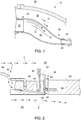
- FIG. 2 is an enlarged, cross-sectional view of a transition piece aft frame assembly 38 8 that includes a portion of the transition piece aft frame 40 and a portion of the first stage nozzle 24.
- the transition piece aft frame assembly 38 includes a radial seal 42, a heat shield 44, a wear strip 46, and an impingement sleeve 48.
- a portion of the heat shield 44 is attached to a portion of an aft face 50 of the transition piece aft frame 40 by any type of joining approach such as, for example, a weld.
- the heat shield 44 may be an extension of the wear strip 46.
- transition piece aft frame assembly 38 may be implemented along all or a portion of the perimeter of the transition piece aft frame 40 (e.g., the configuration may be implemented along the lateral sides of the transition piece at frame 40 as well).
- the exhaust gas stream E is located in the transition piece 20, and the compressor discharge air C is located in the space 30 between the compressor discharge casing 26 and the transition piece 20.
- the compressor discharge air C generally acts as a cooling or a dilution airflow stream that is used to cool the transition piece aft frame 40, as the compressor discharge air C has a lower temperature than the exhaust gas stream E.
- the heat shield 44 is oriented to generally deflect the exhaust gas stream E away from the aft face 50 of the transition piece aft frame 40. Thus, the heat shield 44 generally protects the aft face 50, and provides a barrier between the aft face 50 and the elevated temperatures of the exhaust gas stream E.
- the transition piece aft frame 40 includes a plurality of dilution airflow apertures or passageways, one of which is illustrated in FIG. 2 as a dilution airflow passageway 60.
- the dilution airflow passageway 60 is located therethrough within the transition piece aft frame 40. At least some of the dilution airflow passageways located in the transition piece aft frame 40 receive a portion of the compressor discharge air C. Specifically, the compressor discharge air C passes through an aperture 62 located within the impingement sleeve 48, and is received by the dilution airflow passageway 60.
- the compressor discharge air C flows through the dilution airflow passageway 60 and is directed towards a face 64 of the heat shield 44 that generally opposes the aft face 50 of the transition piece aft frame 40. Specifically, the compressor discharge air C impinges against the face 64 of the heat shield 44, thereby providing cooling to the heat shield 44.
- FIG. 3 is an alternative embodiment of a transition piece aft frame assembly 138 including a portion of a transition piece aft frame 140 and a first stage nozzle 124.
- the transition piece aft frame 140 includes a series of recessed dilution airflow passageways, one of which is shown as a recessed dilution airflow passageway 160.
- the recessed dilution airflow passageway 160 includes a recessed portion 170.
- the recessed portion 170 may include a trench configuration (not illustrated), where each of the recessed dilution airflow passageways 160 share a common recessed portion 170.
- each of the recessed dilution airflow passageways 160 includes an individual recessed portion 170.
- the compressor discharge air C flows through the recessed dilution airflow passageway 160, and impinges or contacts an inner wall 174 of the recessed portion 170 before exiting the transition piece aft frame 140. Impingement of the compressor discharge air C against the inner wall 174 provides enhanced cooling to the transition piece aft frame 140, which in turn may improve or extend the life of the transition piece aft frame 140.
- the position of the recessed portion 170 acts to offset an opening 176 of the recessed dilution airflow passageway 160 from the aft face 150 of the transition piece aft frame 140. Offsetting the opening 176 of the recessed dilution airflow passageway 160 from the aft face 150 of the transition piece aft frame 140 in turn may offset the corresponding stress concentration associated with the opening 176 away from the aft face 150.
- the radial seal 42 includes a heat shield aperture 78 and a first stage nozzle aperture 80.
- a portion of the compressor discharge air C may flow through the heat shield aperture 78 and the first stage nozzle aperture 80.
- a portion of the compressor discharge air C flows through the heat shield aperture 78.
- the heat shield aperture 78 is positioned to direct the compressor discharge air C towards the heat shield 44, where the compressor discharge air C impinges against and cools the heat shield 44.
- a portion of the compressor discharge air C flows through the first stage nozzle aperture 80 as well.
- the first stage nozzle aperture 80 is positioned to direct the compressor discharge air C towards the first stage nozzle 24, where the compressor discharge air C impinges against and cools the first stage nozzle 24.
- Providing the heat shield the first stage nozzle aperture 80 in the heat shield 44 may be necessary in at least some embodiments to provide cooling, as the heat shield 44 may impede or block the flow of the compressor discharge air C to the first stage nozzle 24.
- FIG. 4 is yet another embodiment of a transition piece aft frame assembly 238 including a portion of a transition piece aft frame 240 and a first stage nozzle 224.
- the transition piece aft frame 240 includes a heat shield 244. It should be noted that the transition piece aft frame 240 may also include a radial seal, however the radial seal is not shown in FIG. 4 for clarity.
- a portion 286 of the heat shield 244 is attached to a surface 288 of the transition piece aft frame 240. In the embodiment as shown in FIG. 4 , the portion 286 of the heat shield 244 is generally perpendicular to an aft face 250 of the transition piece aft frame 240.
- portion 286 of the heat shield 244 generally perpendicular to the aft face 250, it is to be understood that the portion 286 of the heat shield 244 may be oriented in relation to the aft face 250 in other configurations as well.
- a portion 290 of the heat shield 244 is generally parallel with the aft face 250 of the transition piece aft frame 240.
- a passageway 282 is located between a face 264 of the heat shield 244 and the aft face 250 of the transition piece aft frame 240.
- the face 264 of the heat shield 244 generally opposes the aft face 250 of the transition piece aft frame 240.
- FIG. 4 also illustrates a transition piece aft frame aperture 284 located therethrough within the heat shield 244.
- the transition piece aft frame aperture 284 allows for the flow or ingression of the compressor discharge air C into the passageway 282.
- the compressor discharge air C flows past and provides cooling to the aft face 250 of the transition piece aft frame 240, as well as the face 264 of the heat shield 244.
- the heat shield 44, 144 and 244 as shown in FIGS. 2-4 provides a barrier and protects the transition piece aft frame 40, 140 and 240 from elevated temperatures created by the exhaust gas stream E.
- the operating temperature of the transition piece aft frame 40, 140, and 240 will be lowered, thereby substantially reducing or eliminating cracking or oxidation of the transition piece aft frame 40, 140 and 240.
- the heat shield 44, 144 and 244 will also reduce the amount of rework for the transition piece aft frame 40, 140 and 240.
- the heat shield 44, 144 and 244 enhances the cooling of the transition piece aft frame 40, 140 and 240, a lower amount of compressor discharge air C may be required to cool the transition piece aft frame 40, 140 and 240, which in turn allows for an improvement in turbine efficiency, or makes the compressor discharge air C available for other regions of the turbine (not shown).
- the heat shield 44, 144 and 244 may also allow for transition piece repair intervals to be extended, which results in significant cost savings.
Claims (10)
- Ensemble de cadre arrière de pièce de transition (38), comprenant :un cadre arrière de pièce de transition (40) ayant une face arrière (50), au moins une partie de la face arrière (50) étant exposée à un courant de gaz d'échappement (E) ;un bouclier thermique (44) raccordé au cadre arrière (40) de la pièce de transition, le bouclier thermique (44) étant orienté pour dévier de manière générale le courant de gaz d'échappement (E) en l'écartant de la face arrière du cadre arrière (40) de la pièce de transition ; etun joint étanche radial (42),caractérisé en ce que le joint étanche radial (42) comprend une ouverture de bouclier thermique (78) qui y est formée et qui est positionnée pour recevoir un courant d'écoulement d'air de dilution, le courant d'écoulement d'air de dilution s'écoulant à travers l'ouverture (78) du bouclier thermique et frappant le bouclier thermique (44).
- Ensemble de cadre arrière de pièce de transition selon la revendication 1, comprenant en outre une bande d'usure (46), dans lequel le bouclier thermique est une extension de la bande d'usure.
- Ensemble de cadre arrière de pièce de transition selon la revendication 1 ou la revendication 2, dans lequel une partie du bouclier thermique (44) est fixée à la face arrière du cadre arrière de la pièce de transition.
- Ensemble de cadre arrière de pièce de transition selon la revendication 1, 2 ou 3, dans lequel le cadre arrière (40) de la pièce de transition comprend au moins un passage de dilution (60) qui le traverse et dans lequel le au moins un passage de dilution est configuré pour recevoir un courant d'écoulement d'air de dilution.
- Ensemble de cadre arrière de pièce de transition selon la revendication 4, dans le courant d'écoulement d'air de dilution est dirigé vers une face du bouclier thermique (44) qu'il frappe, laquelle face est généralement en regard de la face arrière du cadre arrière de la pièce de transition.
- Ensemble de cadre arrière de pièce de transition selon la revendication 4 ou la revendication 5, dans lequel le au moins un passage de dilution (160) comprend une partie évidée (170) dans le cadre arrière (140) de la pièce de transition, dans lequel le courant d'écoulement d'air de dilution frappe une paroi interne de la partie évidée (170) avant de sortie du cadre arrière (140) de la pièce de transition.
- Ensemble de cadre arrière de pièce de transition selon l'une quelconque des revendications précédentes, comprenant en outre une buse de premier étage (24), dans lequel le joint étanche radial (42) comprend une ouverture de buse (80) qui y est formée et qui est positionnée pour recevoir le courant d'écoulement d'air de dilution, le courant d'écoulement d'air de dilution s'écoulant à travers l'ouverture de buse (80) et refroidissant au moins un composant situé entre la buse de premier étage (24) et une pièce de transition.
- Ensemble de cadre arrière de pièce de transition selon l'une quelconque des revendications précédentes, dans lequel un passage (282) est situé entre une face (264) du bouclier thermique (240) et la face arrière (250) du cadre arrière (240) de la pièce de transition, dans lequel la face du bouclier thermique est de manière générale en regard de la face arrière du cadre arrière (240) de la pièce de transition.
- Ensemble de cadre arrière de pièce de transition selon la revendication 8, dans lequel une ouverture (284) du cadre arrière de la pièce de transition est disposée à travers le bouclier thermique (244) et dans lequel l'ouverture (284) du cadre arrière de la pièce de transition permet l'entrée d'un courant d'écoulement d'air de dilution dans le passage (282).
- Système de combustion (10) comprenant :une chambre de combustion (22) ;une pièce de transition (20) pour transporter un courant de gaz d'échappement depuis la chambre de combustion (22), la pièce de transition comprenant une extrémité arrière (36) ;un ensemble (38) de cadre arrière de pièce de transition selon l'une quelconque des revendications précédentes.
Applications Claiming Priority (1)
| Application Number | Priority Date | Filing Date | Title |
|---|---|---|---|
| US13/410,417 US9010127B2 (en) | 2012-03-02 | 2012-03-02 | Transition piece aft frame assembly having a heat shield |
Publications (2)
| Publication Number | Publication Date |
|---|---|
| EP2634372A1 EP2634372A1 (fr) | 2013-09-04 |
| EP2634372B1 true EP2634372B1 (fr) | 2017-07-26 |
Family
ID=47790067
Family Applications (1)
| Application Number | Title | Priority Date | Filing Date |
|---|---|---|---|
| EP13157501.1A Active EP2634372B1 (fr) | 2012-03-02 | 2013-03-01 | Agencement de cadre arrière de pièce de transition avec bouclier thermique et système associé de combustion |
Country Status (5)
| Country | Link |
|---|---|
| US (1) | US9010127B2 (fr) |
| EP (1) | EP2634372B1 (fr) |
| JP (1) | JP6050702B2 (fr) |
| CN (1) | CN103291457B (fr) |
| RU (1) | RU2638416C2 (fr) |
Families Citing this family (6)
| Publication number | Priority date | Publication date | Assignee | Title |
|---|---|---|---|---|
| US9115585B2 (en) * | 2011-06-06 | 2015-08-25 | General Electric Company | Seal assembly for gas turbine |
| CN107075961B (zh) * | 2014-10-28 | 2020-01-03 | 西门子公司 | 供用于涡轮发动机中的位于过渡道和第一排叶片组件之间的密封组件 |
| KR101686336B1 (ko) * | 2015-07-03 | 2016-12-13 | 두산중공업 주식회사 | 가스터빈의 트랜지션피스 연결장치 |
| JP6650849B2 (ja) | 2016-08-25 | 2020-02-19 | 三菱日立パワーシステムズ株式会社 | ガスタービン |
| GB201614711D0 (en) * | 2016-08-31 | 2016-10-12 | Rolls Royce Plc | Axial flow machine |
| JP6966354B2 (ja) * | 2018-02-28 | 2021-11-17 | 三菱パワー株式会社 | ガスタービン燃焼器 |
Family Cites Families (15)
| Publication number | Priority date | Publication date | Assignee | Title |
|---|---|---|---|---|
| US4465284A (en) | 1983-09-19 | 1984-08-14 | General Electric Company | Scalloped cooling of gas turbine transition piece frame |
| JP4031590B2 (ja) * | 1999-03-08 | 2008-01-09 | 三菱重工業株式会社 | 燃焼器の尾筒シール構造及びその構造を用いたガスタービン |
| US6412268B1 (en) | 2000-04-06 | 2002-07-02 | General Electric Company | Cooling air recycling for gas turbine transition duct end frame and related method |
| JP2002243154A (ja) | 2001-02-16 | 2002-08-28 | Mitsubishi Heavy Ind Ltd | ガスタービン燃焼器尾筒出口構造及びガスタービン燃焼器 |
| JP3993484B2 (ja) * | 2002-07-15 | 2007-10-17 | 三菱重工業株式会社 | 燃焼器冷却構造 |
| US6834507B2 (en) * | 2002-08-15 | 2004-12-28 | Power Systems Mfg., Llc | Convoluted seal with enhanced wear capability |
| JP3795036B2 (ja) * | 2003-03-14 | 2006-07-12 | 三菱重工業株式会社 | タービン尾筒のシール構造およびシール装置 |
| JP4191552B2 (ja) | 2003-07-14 | 2008-12-03 | 三菱重工業株式会社 | ガスタービン尾筒の冷却構造 |
| EP1731715A1 (fr) | 2005-06-10 | 2006-12-13 | Siemens Aktiengesellschaft | Transition d'une chambre de combustion à une turbine |
| FR2891300A1 (fr) * | 2005-09-23 | 2007-03-30 | Snecma Sa | Dispositif de controle de jeu dans une turbine a gaz |
| US8001787B2 (en) * | 2007-02-27 | 2011-08-23 | Siemens Energy, Inc. | Transition support system for combustion transition ducts for turbine engines |
| US8245515B2 (en) * | 2008-08-06 | 2012-08-21 | General Electric Company | Transition duct aft end frame cooling and related method |
| US8079219B2 (en) * | 2008-09-30 | 2011-12-20 | General Electric Company | Impingement cooled combustor seal |
| US8092159B2 (en) * | 2009-03-31 | 2012-01-10 | General Electric Company | Feeding film cooling holes from seal slots |
| EP2402659A1 (fr) | 2010-07-01 | 2012-01-04 | Siemens Aktiengesellschaft | Coque extérieure pour chambre de combustion |
-
2012
- 2012-03-02 US US13/410,417 patent/US9010127B2/en active Active
-
2013
- 2013-02-27 JP JP2013036591A patent/JP6050702B2/ja active Active
- 2013-02-28 RU RU2013108923A patent/RU2638416C2/ru not_active IP Right Cessation
- 2013-03-01 CN CN201310065321.5A patent/CN103291457B/zh active Active
- 2013-03-01 EP EP13157501.1A patent/EP2634372B1/fr active Active
Non-Patent Citations (1)
| Title |
|---|
| None * |
Also Published As
| Publication number | Publication date |
|---|---|
| JP6050702B2 (ja) | 2016-12-21 |
| JP2013181749A (ja) | 2013-09-12 |
| CN103291457A (zh) | 2013-09-11 |
| EP2634372A1 (fr) | 2013-09-04 |
| US9010127B2 (en) | 2015-04-21 |
| RU2638416C2 (ru) | 2017-12-13 |
| US20130227964A1 (en) | 2013-09-05 |
| CN103291457B (zh) | 2017-03-01 |
| RU2013108923A (ru) | 2014-09-10 |
Similar Documents
| Publication | Publication Date | Title |
|---|---|---|
| EP2634372B1 (fr) | Agencement de cadre arrière de pièce de transition avec bouclier thermique et système associé de combustion | |
| EP2626600B1 (fr) | Ensemble d'étanchéité de pièce de transition pour turbomachine | |
| JP6189455B2 (ja) | ガスタービンアセンブリの排気セクションのためのパージおよび冷却空気 | |
| JP5753394B2 (ja) | 燃焼器のヘッド端部に高圧空気が供給される燃焼器 | |
| US8851845B2 (en) | Turbomachine vane and method of cooling a turbomachine vane | |
| JP6200170B2 (ja) | ガスタービンを流れる高温ガスを循環させるシステム及び方法 | |
| US8057178B2 (en) | Turbine bucket for a turbomachine and method of reducing bow wave effects at a turbine bucket | |
| US9175857B2 (en) | Combustor cap assembly | |
| US20100077761A1 (en) | Impingement cooled combustor seal | |
| US9470421B2 (en) | Combustor cap assembly | |
| EP2484872B1 (fr) | Système de refroidissement passif pour une turbomachine | |
| JP6110665B2 (ja) | タービン集成体及び集成体の温度を制御するための方法 | |
| CN101922353A (zh) | 从密封槽供给薄膜冷却孔 | |
| JP2014009937A (ja) | ガスタービン用移行ダクト | |
| JP2014009938A (ja) | ガスタービン用トランジションダクト | |
| JP2010508461A (ja) | タービン翼 | |
| US10684016B2 (en) | Aft frame assembly for gas turbine transition piece | |
| US20140130504A1 (en) | System for cooling a hot gas component for a combustor of a gas turbine | |
| US7011492B2 (en) | Turbine vane cooled by a reduced cooling air leak | |
| US20130318996A1 (en) | Cooling assembly for a bucket of a turbine system and method of cooling | |
| US20130236301A1 (en) | Apparatus And System For Directing Hot Gas | |
| JP2014148964A (ja) | ガスタービン尾筒シール及びガスタービン | |
| WO2020046376A1 (fr) | Cadre de sortie de conduit de transition avec refroidissement par impact |
Legal Events
| Date | Code | Title | Description |
|---|---|---|---|
| PUAI | Public reference made under article 153(3) epc to a published international application that has entered the european phase |
Free format text: ORIGINAL CODE: 0009012 |
|
| AK | Designated contracting states |
Kind code of ref document: A1 Designated state(s): AL AT BE BG CH CY CZ DE DK EE ES FI FR GB GR HR HU IE IS IT LI LT LU LV MC MK MT NL NO PL PT RO RS SE SI SK SM TR |
|
| AX | Request for extension of the european patent |
Extension state: BA ME |
|
| 17P | Request for examination filed |
Effective date: 20140304 |
|
| RBV | Designated contracting states (corrected) |
Designated state(s): AL AT BE BG CH CY CZ DE DK EE ES FI FR GB GR HR HU IE IS IT LI LT LU LV MC MK MT NL NO PL PT RO RS SE SI SK SM TR |
|
| GRAP | Despatch of communication of intention to grant a patent |
Free format text: ORIGINAL CODE: EPIDOSNIGR1 |
|
| INTG | Intention to grant announced |
Effective date: 20170228 |
|
| GRAS | Grant fee paid |
Free format text: ORIGINAL CODE: EPIDOSNIGR3 |
|
| GRAJ | Information related to disapproval of communication of intention to grant by the applicant or resumption of examination proceedings by the epo deleted |
Free format text: ORIGINAL CODE: EPIDOSDIGR1 |
|
| GRAL | Information related to payment of fee for publishing/printing deleted |
Free format text: ORIGINAL CODE: EPIDOSDIGR3 |
|
| INTC | Intention to grant announced (deleted) | ||
| GRAR | Information related to intention to grant a patent recorded |
Free format text: ORIGINAL CODE: EPIDOSNIGR71 |
|
| GRAA | (expected) grant |
Free format text: ORIGINAL CODE: 0009210 |
|
| INTG | Intention to grant announced |
Effective date: 20170614 |
|
| AK | Designated contracting states |
Kind code of ref document: B1 Designated state(s): AL AT BE BG CH CY CZ DE DK EE ES FI FR GB GR HR HU IE IS IT LI LT LU LV MC MK MT NL NO PL PT RO RS SE SI SK SM TR |
|
| REG | Reference to a national code |
Ref country code: GB Ref legal event code: FG4D |
|
| REG | Reference to a national code |
Ref country code: CH Ref legal event code: EP |
|
| REG | Reference to a national code |
Ref country code: AT Ref legal event code: REF Ref document number: 912577 Country of ref document: AT Kind code of ref document: T Effective date: 20170815 |
|
| REG | Reference to a national code |
Ref country code: IE Ref legal event code: FG4D |
|
| REG | Reference to a national code |
Ref country code: DE Ref legal event code: R096 Ref document number: 602013023945 Country of ref document: DE |
|
| REG | Reference to a national code |
Ref country code: NL Ref legal event code: MP Effective date: 20170726 |
|
| REG | Reference to a national code |
Ref country code: LT Ref legal event code: MG4D |
|
| REG | Reference to a national code |
Ref country code: AT Ref legal event code: MK05 Ref document number: 912577 Country of ref document: AT Kind code of ref document: T Effective date: 20170726 |
|
| PG25 | Lapsed in a contracting state [announced via postgrant information from national office to epo] |
Ref country code: LT Free format text: LAPSE BECAUSE OF FAILURE TO SUBMIT A TRANSLATION OF THE DESCRIPTION OR TO PAY THE FEE WITHIN THE PRESCRIBED TIME-LIMIT Effective date: 20170726 Ref country code: SE Free format text: LAPSE BECAUSE OF FAILURE TO SUBMIT A TRANSLATION OF THE DESCRIPTION OR TO PAY THE FEE WITHIN THE PRESCRIBED TIME-LIMIT Effective date: 20170726 Ref country code: FI Free format text: LAPSE BECAUSE OF FAILURE TO SUBMIT A TRANSLATION OF THE DESCRIPTION OR TO PAY THE FEE WITHIN THE PRESCRIBED TIME-LIMIT Effective date: 20170726 Ref country code: HR Free format text: LAPSE BECAUSE OF FAILURE TO SUBMIT A TRANSLATION OF THE DESCRIPTION OR TO PAY THE FEE WITHIN THE PRESCRIBED TIME-LIMIT Effective date: 20170726 Ref country code: NO Free format text: LAPSE BECAUSE OF FAILURE TO SUBMIT A TRANSLATION OF THE DESCRIPTION OR TO PAY THE FEE WITHIN THE PRESCRIBED TIME-LIMIT Effective date: 20171026 Ref country code: NL Free format text: LAPSE BECAUSE OF FAILURE TO SUBMIT A TRANSLATION OF THE DESCRIPTION OR TO PAY THE FEE WITHIN THE PRESCRIBED TIME-LIMIT Effective date: 20170726 Ref country code: AT Free format text: LAPSE BECAUSE OF FAILURE TO SUBMIT A TRANSLATION OF THE DESCRIPTION OR TO PAY THE FEE WITHIN THE PRESCRIBED TIME-LIMIT Effective date: 20170726 |
|
| PG25 | Lapsed in a contracting state [announced via postgrant information from national office to epo] |
Ref country code: IS Free format text: LAPSE BECAUSE OF FAILURE TO SUBMIT A TRANSLATION OF THE DESCRIPTION OR TO PAY THE FEE WITHIN THE PRESCRIBED TIME-LIMIT Effective date: 20171126 Ref country code: ES Free format text: LAPSE BECAUSE OF FAILURE TO SUBMIT A TRANSLATION OF THE DESCRIPTION OR TO PAY THE FEE WITHIN THE PRESCRIBED TIME-LIMIT Effective date: 20170726 Ref country code: GR Free format text: LAPSE BECAUSE OF FAILURE TO SUBMIT A TRANSLATION OF THE DESCRIPTION OR TO PAY THE FEE WITHIN THE PRESCRIBED TIME-LIMIT Effective date: 20171027 Ref country code: PL Free format text: LAPSE BECAUSE OF FAILURE TO SUBMIT A TRANSLATION OF THE DESCRIPTION OR TO PAY THE FEE WITHIN THE PRESCRIBED TIME-LIMIT Effective date: 20170726 Ref country code: BG Free format text: LAPSE BECAUSE OF FAILURE TO SUBMIT A TRANSLATION OF THE DESCRIPTION OR TO PAY THE FEE WITHIN THE PRESCRIBED TIME-LIMIT Effective date: 20171026 Ref country code: LV Free format text: LAPSE BECAUSE OF FAILURE TO SUBMIT A TRANSLATION OF THE DESCRIPTION OR TO PAY THE FEE WITHIN THE PRESCRIBED TIME-LIMIT Effective date: 20170726 Ref country code: RS Free format text: LAPSE BECAUSE OF FAILURE TO SUBMIT A TRANSLATION OF THE DESCRIPTION OR TO PAY THE FEE WITHIN THE PRESCRIBED TIME-LIMIT Effective date: 20170726 |
|
| REG | Reference to a national code |
Ref country code: FR Ref legal event code: PLFP Year of fee payment: 6 |
|
| PG25 | Lapsed in a contracting state [announced via postgrant information from national office to epo] |
Ref country code: RO Free format text: LAPSE BECAUSE OF FAILURE TO SUBMIT A TRANSLATION OF THE DESCRIPTION OR TO PAY THE FEE WITHIN THE PRESCRIBED TIME-LIMIT Effective date: 20170726 Ref country code: CZ Free format text: LAPSE BECAUSE OF FAILURE TO SUBMIT A TRANSLATION OF THE DESCRIPTION OR TO PAY THE FEE WITHIN THE PRESCRIBED TIME-LIMIT Effective date: 20170726 Ref country code: DK Free format text: LAPSE BECAUSE OF FAILURE TO SUBMIT A TRANSLATION OF THE DESCRIPTION OR TO PAY THE FEE WITHIN THE PRESCRIBED TIME-LIMIT Effective date: 20170726 |
|
| REG | Reference to a national code |
Ref country code: DE Ref legal event code: R097 Ref document number: 602013023945 Country of ref document: DE |
|
| PG25 | Lapsed in a contracting state [announced via postgrant information from national office to epo] |
Ref country code: SK Free format text: LAPSE BECAUSE OF FAILURE TO SUBMIT A TRANSLATION OF THE DESCRIPTION OR TO PAY THE FEE WITHIN THE PRESCRIBED TIME-LIMIT Effective date: 20170726 Ref country code: SM Free format text: LAPSE BECAUSE OF FAILURE TO SUBMIT A TRANSLATION OF THE DESCRIPTION OR TO PAY THE FEE WITHIN THE PRESCRIBED TIME-LIMIT Effective date: 20170726 Ref country code: IT Free format text: LAPSE BECAUSE OF FAILURE TO SUBMIT A TRANSLATION OF THE DESCRIPTION OR TO PAY THE FEE WITHIN THE PRESCRIBED TIME-LIMIT Effective date: 20170726 Ref country code: EE Free format text: LAPSE BECAUSE OF FAILURE TO SUBMIT A TRANSLATION OF THE DESCRIPTION OR TO PAY THE FEE WITHIN THE PRESCRIBED TIME-LIMIT Effective date: 20170726 |
|
| PGFP | Annual fee paid to national office [announced via postgrant information from national office to epo] |
Ref country code: FR Payment date: 20180326 Year of fee payment: 6 |
|
| PLBE | No opposition filed within time limit |
Free format text: ORIGINAL CODE: 0009261 |
|
| STAA | Information on the status of an ep patent application or granted ep patent |
Free format text: STATUS: NO OPPOSITION FILED WITHIN TIME LIMIT |
|
| 26N | No opposition filed |
Effective date: 20180430 |
|
| PG25 | Lapsed in a contracting state [announced via postgrant information from national office to epo] |
Ref country code: SI Free format text: LAPSE BECAUSE OF FAILURE TO SUBMIT A TRANSLATION OF THE DESCRIPTION OR TO PAY THE FEE WITHIN THE PRESCRIBED TIME-LIMIT Effective date: 20170726 |
|
| REG | Reference to a national code |
Ref country code: CH Ref legal event code: PL |
|
| GBPC | Gb: european patent ceased through non-payment of renewal fee |
Effective date: 20180301 |
|
| PG25 | Lapsed in a contracting state [announced via postgrant information from national office to epo] |
Ref country code: MC Free format text: LAPSE BECAUSE OF FAILURE TO SUBMIT A TRANSLATION OF THE DESCRIPTION OR TO PAY THE FEE WITHIN THE PRESCRIBED TIME-LIMIT Effective date: 20170726 |
|
| REG | Reference to a national code |
Ref country code: BE Ref legal event code: MM Effective date: 20180331 |
|
| REG | Reference to a national code |
Ref country code: IE Ref legal event code: MM4A |
|
| PG25 | Lapsed in a contracting state [announced via postgrant information from national office to epo] |
Ref country code: LU Free format text: LAPSE BECAUSE OF NON-PAYMENT OF DUE FEES Effective date: 20180301 |
|
| PG25 | Lapsed in a contracting state [announced via postgrant information from national office to epo] |
Ref country code: IE Free format text: LAPSE BECAUSE OF NON-PAYMENT OF DUE FEES Effective date: 20180301 |
|
| PG25 | Lapsed in a contracting state [announced via postgrant information from national office to epo] |
Ref country code: GB Free format text: LAPSE BECAUSE OF NON-PAYMENT OF DUE FEES Effective date: 20180301 Ref country code: BE Free format text: LAPSE BECAUSE OF NON-PAYMENT OF DUE FEES Effective date: 20180331 Ref country code: LI Free format text: LAPSE BECAUSE OF NON-PAYMENT OF DUE FEES Effective date: 20180331 Ref country code: CH Free format text: LAPSE BECAUSE OF NON-PAYMENT OF DUE FEES Effective date: 20180331 |
|
| PG25 | Lapsed in a contracting state [announced via postgrant information from national office to epo] |
Ref country code: MT Free format text: LAPSE BECAUSE OF NON-PAYMENT OF DUE FEES Effective date: 20180301 |
|
| PG25 | Lapsed in a contracting state [announced via postgrant information from national office to epo] |
Ref country code: FR Free format text: LAPSE BECAUSE OF NON-PAYMENT OF DUE FEES Effective date: 20190331 |
|
| PG25 | Lapsed in a contracting state [announced via postgrant information from national office to epo] |
Ref country code: TR Free format text: LAPSE BECAUSE OF FAILURE TO SUBMIT A TRANSLATION OF THE DESCRIPTION OR TO PAY THE FEE WITHIN THE PRESCRIBED TIME-LIMIT Effective date: 20170726 |
|
| PG25 | Lapsed in a contracting state [announced via postgrant information from national office to epo] |
Ref country code: HU Free format text: LAPSE BECAUSE OF FAILURE TO SUBMIT A TRANSLATION OF THE DESCRIPTION OR TO PAY THE FEE WITHIN THE PRESCRIBED TIME-LIMIT; INVALID AB INITIO Effective date: 20130301 Ref country code: PT Free format text: LAPSE BECAUSE OF FAILURE TO SUBMIT A TRANSLATION OF THE DESCRIPTION OR TO PAY THE FEE WITHIN THE PRESCRIBED TIME-LIMIT Effective date: 20170726 |
|
| PG25 | Lapsed in a contracting state [announced via postgrant information from national office to epo] |
Ref country code: MK Free format text: LAPSE BECAUSE OF NON-PAYMENT OF DUE FEES Effective date: 20170726 Ref country code: CY Free format text: LAPSE BECAUSE OF FAILURE TO SUBMIT A TRANSLATION OF THE DESCRIPTION OR TO PAY THE FEE WITHIN THE PRESCRIBED TIME-LIMIT Effective date: 20170726 |
|
| PG25 | Lapsed in a contracting state [announced via postgrant information from national office to epo] |
Ref country code: AL Free format text: LAPSE BECAUSE OF FAILURE TO SUBMIT A TRANSLATION OF THE DESCRIPTION OR TO PAY THE FEE WITHIN THE PRESCRIBED TIME-LIMIT Effective date: 20170726 |
|
| REG | Reference to a national code |
Ref country code: DE Ref legal event code: R081 Ref document number: 602013023945 Country of ref document: DE Owner name: GENERAL ELECTRIC TECHNOLOGY GMBH, CH Free format text: FORMER OWNER: GENERAL ELECTRIC CO., SCHENECTADY, N.Y., US |
|
| PGFP | Annual fee paid to national office [announced via postgrant information from national office to epo] |
Ref country code: DE Payment date: 20240220 Year of fee payment: 12 |