EP2633539B1 - Verfahren und vorrichtung zur betätigung eines konfigurierbaren elektromagneten - Google Patents
Verfahren und vorrichtung zur betätigung eines konfigurierbaren elektromagneten Download PDFInfo
- Publication number
- EP2633539B1 EP2633539B1 EP11836970.1A EP11836970A EP2633539B1 EP 2633539 B1 EP2633539 B1 EP 2633539B1 EP 11836970 A EP11836970 A EP 11836970A EP 2633539 B1 EP2633539 B1 EP 2633539B1
- Authority
- EP
- European Patent Office
- Prior art keywords
- solenoid
- current
- voltage
- module
- coil
- Prior art date
- Legal status (The legal status is an assumption and is not a legal conclusion. Google has not performed a legal analysis and makes no representation as to the accuracy of the status listed.)
- Active
Links
Images





Classifications
-
- H—ELECTRICITY
- H01—ELECTRIC ELEMENTS
- H01H—ELECTRIC SWITCHES; RELAYS; SELECTORS; EMERGENCY PROTECTIVE DEVICES
- H01H47/00—Circuit arrangements not adapted to a particular application of the relay and designed to obtain desired operating characteristics or to provide energising current
- H01H47/22—Circuit arrangements not adapted to a particular application of the relay and designed to obtain desired operating characteristics or to provide energising current for supplying energising current for relay coil
-
- H—ELECTRICITY
- H01—ELECTRIC ELEMENTS
- H01F—MAGNETS; INDUCTANCES; TRANSFORMERS; SELECTION OF MATERIALS FOR THEIR MAGNETIC PROPERTIES
- H01F7/00—Magnets
- H01F7/06—Electromagnets; Actuators including electromagnets
- H01F7/08—Electromagnets; Actuators including electromagnets with armatures
- H01F7/18—Circuit arrangements for obtaining desired operating characteristics, e.g. for slow operation, for sequential energisation of windings, for high-speed energisation of windings
- H01F7/1805—Circuit arrangements for holding the operation of electromagnets or for holding the armature in attracted position with reduced energising current
-
- H—ELECTRICITY
- H01—ELECTRIC ELEMENTS
- H01H—ELECTRIC SWITCHES; RELAYS; SELECTORS; EMERGENCY PROTECTIVE DEVICES
- H01H47/00—Circuit arrangements not adapted to a particular application of the relay and designed to obtain desired operating characteristics or to provide energising current
- H01H47/22—Circuit arrangements not adapted to a particular application of the relay and designed to obtain desired operating characteristics or to provide energising current for supplying energising current for relay coil
- H01H47/32—Energising current supplied by semiconductor device
Definitions
- the present invention relates generally to methods and apparatus for driving solenoids, and more particularly to a configurable connectorized apparatus for driving a solenoid coil.
- Solenoids are widely used throughout the world. Thus solenoids actuate relays or contactors that apply power to the starter motor of most cars. Solenoids actuate the lock mechanism in most keyless door systems. Most automatic valves, whether pneumatic or fluidic, employ solenoids to actuate or pilot the valve. Solenoids are found in factories, buildings, cars and homes.
- Fig. 1 depicts a generic solenoid 10 showing its principal constituent parts.
- the two leadwires, 2, convey electrical current to the solenoid coil 3 which generates a magnetic field.
- the magnetic circuit of said solenoid 10 includes the metal case 4 and the air gap 6.
- the armature 5 is influenced by the magnetic field and a force will attempt to move or hold the armature 5 in the direction of the hardstop 8. When said armature 5 contacts and remains in contact with said hardstop 8, it is said to be scaled.
- Various features are often added to said armature 5 such as the hole 7 in order to attach a mechanism to the armature 5 and thereby complete the mechanical linkage to the solenoid mechanism.
- the return mechanism such as a spring, which tends to return said solenoid 10 to its open position when electrical current is removed from said solenoid 10.
- Solenoids transduce the flow of electrical current into motion via force on the moving portion of the solenoid called the armature.
- the armature of a solenoid may be connected to various mechanisms, thus in a relay, the armature motion opens or closes electrical contacts whereas in a solenoid-operated valve, the armature is often directly connected to one side of a valve seal.
- the solenoid operates a smaller so-called pilot valve that employs some fluidic or pneumatic amplification, but the basic operation of the valve is initiated by the solenoid action.
- solenoids are essential components in a wide range of mechanisms that perform among other things, electrical switching, latching, braking, clamping, valving, diverting or connecting.
- Figs. 2-4 provide examples of circuits used for driving solenoids.
- Fig. 2 depicts a common prior art transistor solenoid drive circuit including transistor 11 which is capable of conducting electrical current in response to a signal on its input. Said electrical current will flow through solenoid 10.
- a flyback diode 14 conducts electrical current in order to prevent the inductive component of said solenoid 10 from increasing the voltage seen by said transistor 11 and possibly destroying said transistor 11.
- said current ceases and said solenoid 10 is thus de-energized.
- Fig. 3 depicts a solenoid driver integrated circuit 12 such as is commercially available from a number of manufacturers and employing pulse width modulation (PWM) of the supply voltage in order to reduce the holding current to the solenoid 10.
- PWM pulse width modulation
- Connected to said solenoid driver 12 is said solenoid 10 as well as two of the commonly required external components, a flyback diode 14 and a series-connected diode 13 intended to both prevent damage to said driver integrated circuit 12 and to somewhat reduce electrical radiation from the PWM switching transients.
- Said solenoid driver integrated circuit 12 is fixed configuration and cannot be reconfigured for other purposes such as measuring or producing voltages or currents other than required for the narrow solenoid drive task at hand.
- Fig. 4 depicts a typical prior art fixed configuration sinking output module 17 capable of driving solenoid 10.
- said output module 17 does not provide power to drive said solenoid 10 but instead relies upon connecting and disconnecting power provided by external device power supply 18.
- terminal blocks 19 are employed to effect the wiring to said solenoid 10.
- a protective flyback diode 14 is installed to reduce voltages produced by said solenoid 10 during the de-energization process.
- solenoid-driven mechanism design there is a delicate balance between providing sufficient solenoid force at a desired distance of travel and generating excessive energy consumption and heating in the solenoid coil.
- the amount of electrical current required to move the solenoid to its closed position is high compared to the electrical current required to keep the solenoid closed-or sealed as is the term of art.
- a solenoid that is to remain sealed for a long period of time tends to become hot and consume a large amount of energy compared to what is needed just to hold the solenoid sealed.
- the delicate balance for the solenoid-driven mechanism designer is to build a solenoid that will reliably move a given distance to the sealed position while at the same time not consuming excessive electrical power or overheating despite constant application of power to the solenoid coil.
- the solenoid transduces the flow of electrical current to force on the armature
- said force is not a constant function of electrical current.
- the solenoid When the solenoid is sealed, there is essentially no air gap in the magnetic circuit, thus the magnetic flux is relatively high at a given electrical current.
- the solenoid when the solenoid is fully open, there exists an air gap in the magnetic circuit that significantly increases the electrical reluctance of the circuit, said reluctance being the ratio of magnetomotive force (MMF) to magnetic flux developed.
- MMF magnetomotive force
- Suzuki teaches that building a current control circuit can allow cutting back the current to the relay coil after the relay has closed.
- the circuit of Suzuki requires that a series-wired transistor throttle the current to the relay coil thus creating heat and reducing the possible energy savings considerably.
- Suzuki's invention does somewhat reduce solenoid heating but by moving some of the heat generation to a transistor. For example, if Suzuki reduced the holding solenoid current to 1 ⁇ 2 or the initial pull-in current, then the system of Suzuki would see solenoid energy use go down to 1 ⁇ 4 of the previous level. Unfortunately, another 1 ⁇ 4 of said energy is burned up in ohmic losses in the transistor.
- Suzuki does not mention a strategy for dealing with the effect of the relay coil inductance during relay turn-off. It is well understood in the art that employing a transistor to remove power from an inductor will result in a large voltage swing that in general must be mitigated by inserting a path for current to flow thus avoiding a dangerous increase in circuit voltage. Generally, a diode is employed that will allow the relay coil current to circulate during turn-off.
- PWM pulse width modulation
- a class of integrated circuits such as Texas Instruments DRV102 PWM Valve/Solenoid Driver, has aimed to produce a fixed and dedicated electrical circuit capable of initially driving the solenoid with full voltage and consequently full current and subsequently reducing said current by performing PWM of the power signal to the solenoid.
- said integrated circuits can produce undesirable electrical interference as described earlier.
- an application note for the Texas Instruments DRV102 states, "The PWM switching voltages and currents can cause electromagnetic radiation.”
- determining the location of noise reducing components may defy logic", i.e. may be difficult to predict and require repetitive empirical testing.
- such integrated circuits usually require the addition of a number of external components and are fixed configuration: the connector to which the solenoid is attached can only drive a solenoid.
- the present invention as explained below provides additional applications and flexibility that is not available using these prior art devices.
- solenoid driving how to determine if a solenoid is sealed.
- a solenoid can fail to reach or stay at its closed or sealed position upon the application of electrical current for a number of reasons.
- the solenoid may be jammed and unable to initially move in either direction.
- the solenoid coil may be open or not electrically continuous and therefore incapable of generating the required magnetic field.
- the solenoid coil may be shorted.
- the solenoid may be exposed to vibration that puts a sufficient force on the solenoid to unseal it. Or, there could be a momentary loss of electrical current that results in the solenoid holding force being reduced briefly.
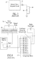
- Fig. 5 depicts the prior art apparatus for determining the state of the solenoid, whether sealed or open.
- the controller 90 commands a solenoid coil 91 to close. After the solenoid 91 has been given sufficient time to seal, the controller 90 then senses the state of the auxiliary contact 92 which is mechanically linked to the solenoid mechanism.
- said controller 90 can deduce the state of the solenoid 91.
- said solenoid 10 if the solenoid 10 is not a relay, then said solenoid 10 must be mechanically connected to said auxiliary contact 92, such connection being problematic and costly. Even in the case where the solenoid is part of a relay, this strategy requires using one set of contacts for this monitoring process. Additional electrical circuits are required to monitor this extra contact, and for systems employing reduced holding current, the actuation sequence must be repeated. In the case where the solenoid is not a part of a relay, then a set of contacts must be added to the solenoid mechanism. This requirement is prohibitive except for the most critical solenoid systems.
- DE 100 03 531 A1 discloses a load switching method.
- Embodiments provide a configurable connectorized method and apparatus for driving a solenoid coil, capable of providing a sufficiently high force to move the solenoid from its fully open position to its sealed position. It can also reduce the energy consumed and the heating of the solenoid coil when the solenoid is sealed.
- the present invention reduces the energy without continuous losses from a series throttling transistor or resistor.
- the invention facilitates detection of a solenoid coil which is open or shorted, and can reduce the current on a solenoid for which the armature is jammed in order to reduce the consequential overheating of the coil.
- the present invention eliminates the requirement to use PWM as the drive method, and handles coil turn-off behavior without the need for additional components such as diodes.
- the present invention simplifies connections to one or more relays or solenoids without the requirement for external power supplies.
- the present invention allows determination of whether a solenoid is sealed without the need for auxiliary electrical contacts, and can use information about the solenoid unsealed state to essentially instantaneously increase the force on the solenoid armature to cause the armature to return to its sealed position before the armature has moved significantly.
- the present invention extends the teachings of U. S. Patent Nos. 6,892,265 , 7,216,191 and 7,822,896 and U. S. Patent Application No. 13/069,292 , published as Patent Appl. Publ. No. US 2011/0231176 .
- a configurable connectorized system is described in which any connector pin of such a system may be configured for a wide variety of electrical functions, such as measuring a voltage, producing a voltage, measuring a current, producing a current, producing various power levels or even handling frequency information such as serial communication data.
- the configurable, connectorized input/output module dramatically reduces the number of additional components required such as power supplies and terminal blocks.
- the configurable, connectorized input/output system eliminates the need for many different fixed-configuration modules by virtue of its ability to change the electrical configuration of its connector pins.
- the present invention enables the pin configuration of the input/output module to be changed during normal operation, thus if a solenoid is connected between two such pins, the voltage across the solenoid may be changed without any added components or without the required use of PWM. Because the present invention enables the pin configuration to be changed from one power supply to another or varying the voltage level of any said multiple power supplies, the invention allows high efficiency power supplies to be used. Therefore, no throttling or PWM is required to reduce the voltage across the solenoid, although nothing precludes the use of PWM in the present invention should it, for some reason, be determined to be beneficial. In addition, the present invention also provides two ways to handle the inductive current at turn-off.
- the configurable connectorized module can throttle the current gradually while holding the coil voltage within an acceptable level.
- the first of one of the solenoid's two pins may be again reconfigured to the same voltage as the second pin thus connecting both sides of the solenoid coil to the same power supply, either high side or low side. In both ways, the effect of the inductance of the coil during circuit turnoff is addressed, and no additional components are required to provide for safe circuit operation.
- the present invention provides for connecting other sensing and sourcing circuit elements to the connector pin, it is possible to determine whether the solenoid is sealed. Said determination is based upon the fact that the electrical inductance of the solenoid is inversely related to the electrical reluctance and said reluctance decreases as the solenoid air gap goes to zero. Said determination is achieved by imposing either a periodic or step change to voltage across the solenoid and measuring the resulting periodic or step change in current. Said resulting current is a function of solenoid inductance. Or, alternatively, said determination may be achieved by making either a step change or a periodic change to the current through the solenoid and measuring the resulting change in voltage, although the preferred embodiment is the former method of determination.
- Said determination includes whether the solenoid is sealed, opening or open.
- the method and apparatus of the present invention is capable of essentially simultaneously increasing the solenoid current to reseal the solenoid, thus preventing unintended opening of the solenoid. Said resealing can be effected without any additional apparatus than is found in the present invention.
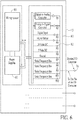
- Fig. 6 depicts a functional block diagram of the configurable connectorized input/output module 15 of the present invention. Included inside said module 15 of the preferred embodiment is a microprocessor 80 which is capable of directing any of a plurality of signals to one or more pins 16 which are subsequently to be connected to various sensors and actuators such as solenoid, but by no means limited to solenoids.
- said configurable connectorized input/output module 15 contains one or more power supplies 81 which may be routed in the same manner as other of the plurality of signals via switching means 82 such as R5 or R6 and connect to one or more connector pins 16. When a solenoid is connected between two such pins 16, the configurable connectorized input/output module 15 can produce one of a plurality of power levels to said solenoid thereby adjusting the current flowing through the solenoid without the need for PWM.
- the configurable input/output module 15 may contain any number of interconnection apparatus 83.
- Each interconnection apparatus 83 is connected to one device connector 16 and optionally through an internal cross point switch to another interconnection apparatus. ( See FIG. 13 and related description.)
- FIG. 6 is highly stylized and is intended to convey the essence of the module of the present invention.
- Fig. 7 depicts the configurable connectorized input/output module 15 of the present invention when connected to a solenoid 10.
- said module 15 has been configured by the microprocessor 80 to route a plurality of power levels from power supplies 81 to pins 1 and 2 of said module 15. Any of the 15 pins shown in Fig. 7 could have been configured for this function, unlike prior art fixed-configuration output modules.
- the prior art fixed-configuration output module where a flyback diode is required to protect the output module, none is required by the present invention and thus none is shown.
- the configurable, connectorized input/output module 15 of the present invention is thus able to cause one of a plurality of voltages to be applied to the connected solenoid 10 thus effecting the goals of the present invention.
- Figs. 8A, 8B and 8C depict the voltage and current waveforms resulting from the actuation of the solenoid 10 using a snubbing turnoff method and apparatus, and shown as Solenoid Drive Signal in Fig. 8A .
- the solenoid voltage is zero which is the idle state of the solenoid.
- the solenoid is unpowered and ready to be actuated.
- the configurable connectorized input/output module 15 connects the actuation-level voltage to the solenoid 10.
- said activation-level voltage is 24V.
- current in the solenoid coil rapidly increases, 40, and the solenoid moves smartly because the imposed voltage is preferably higher than the sustainable steady state coil voltage.
- the duration of phase 23 it is possible to control the solenoid actuation force.
- phase 23 the configurable connectorized input/output module 15 maintains the pull-in-level voltage on the solenoid coil and the coil current moves asymptotically to steady state, 41.
- the length of the Phase 23 portion is sized such that said solenoid current may not reach steady state in order to control the solenoid actuation force.
- the solenoid is preferentially in its closed or sealed position.
- the configurable connectorized input/output module 15 essentially simultaneously disconnects the actuation-level voltage from the solenoid and connects the sustain-level voltage to the solenoid.
- the voltage level of a single power supply can be varied to achieve the same goal.
- the sustain-level voltage is chosen to provide ample holding force for the solenoid, whereas said sustain-level voltage might not be sufficient to reliably pull in the solenoid under all conditions.
- Said sustain-level voltage can preferentially be adjusted by the microprocessor 80.
- the solenoid coil current 42 begins to decrease in response to the lower applied voltage.
- Said solenoid coil current decreases to a steady state 43 after some time period which is a function of the solenoid electrical characteristics.
- Phase 25 the sustain-level voltage is maintained on the solenoid in order to keep the solenoid sealed.
- Phase 25 is maintained as long as required by the control system. This time can range from milliseconds to months or longer.
- Phase 26 the process is begun to remove power from the solenoid in response to the solenoid drive signal becoming false, 31..
- the configurable solenoid drive circuit cannot simply open its drive transistors to the solenoid because the inductance of the solenoid coil-which makes rapid reduction in current infeasible-would cause the voltage at the configurable connectorized input/output module pin 16 to become very negative with respect to ground and likely damage or destroy the switching means 82. If the solenoid coil is equipped with a so-called flyback diode, then said solenoid current is provided a path while the coil energy is dissipated. If, however, there is no flyback diode, then the coil voltage will cross zero volts and become negative.
- the configurable connectorized input/output module 15 of the present invention is therefore configured to begin to throttle the coil current and clamp the coil voltage to a value, which in the preferred embodiment is approximately -5V with respect to ground.
- Phase 27 the throttling process continues until the voltage that the coil is capable of sourcing falls to less than the clamped voltage. During Phase 27, the solenoid coil current 44 decreases linearly.
- the configurable connectorized input/output module 15 stops actively throttling the solenoid coil current and instead provides a fixed transistor gate drive thus dissipating the remaining energy from the solenoid coil.
- the solenoid current, 45 decays exponentially to zero during Phase 28, and the solenoid coil returns to its idle state.
- the solenoid coil In Phase 29, the solenoid coil is in the same state as it was in Phase 21: the coil is quiescent, the solenoid is not engaged and the solenoid is again ready to be actuated.
- the solenoid coil current, 46, is also zero.
- the interface apparatus 84 may be configured to connect one of a plurality of power supplies to the device connector 16 to which the solenoid 10 is connected.
- switching means 82 can initially be caused to connect a 24VDC power supply to said device connector 16 in order to achieve the solenoid pull-in phase.
- said interface apparatus 84 may then be caused to connect a 5VDC power supply to said device connector 16 in order to achieve the solenoid sustaining phase.
- Figs. 9A, 9B and 9C are very similar to Figs. 8A, 8B and 8C with the exception that rather than throttling the solenoid current, the two pins of the configurable connectorized input/output module 15 which are connected to the solenoid 10 are set to the same voltage, either high-side or low-side. In so doing, the solenoid current flows through said module 15 until the solenoid current is exhausted. Thus phase 27 in Fig. 9B remains at zero volts, not -5 volts as in Fig. 8B . And the current in Fig. 9C decreases asymptotically to zero in phase 46.
- determining the state of the solenoid, whether sealed, opening or fully open is achieved by measuring the inductance of the solenoid coil, since said inductance is inversely proportional to reluctance which is itself a function of the solenoid air gap: reluctance decreases as air gap decreases and then further decreases when the solenoid fully seals and the air gap is essentially eliminated.
- the present invention provides a number of methods and a number of apparatuses to measure said inductance. Two methods and two apparatuses will be described, but are intended to be for illustrative purposes only. Simpler or more appropriate methods using other features of the present invention are possible but this description is intended to convey the essence of the invention.
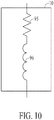
- Fig. 10 depicts a common electrical circuit model used to describe the inductance measurement of the present invention. Specifically, the solenoid 10 has been broken down into two constituent parts. Its resistive component 95 is series-connected to its inductive component 96. This model will facilitate the description of the inductance measurement system.
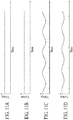
- Fig. 11A depicts the DC voltage across a solenoid. Said voltage may be any appropriate value greater than or equal to zero volts.
- Fig. 11B depicts the resulting DC current given the applied voltage depicted in Fig. 11A , said resulting DC current being greater than or equal to zero.
- Fig. 11C depicts a sinusoidal voltage signal of suitable frequency imposed upon the DC voltage signal of Fig. 11A , said sinusoidal voltage being a sufficiently small percentage of the DC voltage as not to affect the operation of the solenoid but sufficiently large to generate a measurable current in said solenoid 10.
- Said sinusoidal voltage signal is established by making small changes to the voltage setpoint of any of the multiple power supplies 81 connected to the configurable connectorized input/output module 15 of the present invention.
- Said sinusoidal voltage signal will cause a variation in the DC current signal of Fig. 11B that is also essentially sinusoidal. Said variation in the DC current signal is shown in Fig. 11D .
- the phase of the signal of Fig. 11D with respect to the sinusoidal voltage signal of Fig 11C will be a function of the relative magnitudes of the two constituent elements depicted in Fig. 10 , the resistive 95 and inductive 96 components of said solenoid 10. Specifically, if the resistive element 95 of Fig. 10 were to be large and the inductive component 96 of Fig. 10 were to be small, then the phase of the current signal of Fig. 11D with respect to the voltage signal of Fig. 11C will be small and closer to 0 degrees than 90 degrees.
- inductance measurements such as periodic square wave excitation rather than periodic sine wave excitation with similar results and perhaps a simpler and more effective embodiment.
- step changes in voltage or current and the subsequent measurement of the response in current or voltage can provide similar inductance measurements in an embodiment that may be more appropriate for the electronic circuits employed.
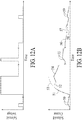
- FIG. 12A depicts solenoid voltage for a typical energization and de-energization sequence, with state query pulses used to determine whether the solenoid is sealed. The magnitude or polarity, and the duration of these query pulses are designed to avoid altering the state of the solenoid.
- Fig. 12B depicts the solenoid current response to this sequence in Fig. 12A and its query pulses.
- the three voltages imposed across the relay in this method would, in a preferred embodiment, be the same levels used for energization, holding, and de-energization, although this is not a critical aspect of the present invention. This method will now be described in detail, in the order of events or phases in the depicted sequence.
- the solenoid is de-energized, with zero current and voltage.
- query pulses of sufficiently small amplitude and duration can be applied to produce the current response 50 without moving the solenoid armature.
- the solenoid inductance can be inferred with one sample provided the query pulse duration is short in comparison to the L/R time-constant of the solenoid in its sealed or unsealed state, or in between states. As described previously, this inductance indicates the solenoid state, an object of the invention.
- the solenoid is energized, producing the current response 51 and one of the current responses 52 or 53, depending upon whether the solenoid armature moves or not. Because the inductance can be measured for the de-energized state, and because responses 51 and 53 are both part of a simple, real exponential determined by that known inductance and the resistance known by other means, this non-moving pin response can be readily distinguished from the response pair 51 and 52 which exhibit markedly different trajectories. This distinction may be made by sampling the current at times along the response whose time-separation is short in comparison to the L/R time-constant, permitting a simple computation by microprocessor 80 to detect the trajectory departure 52 from the simple, real exponential, which departure indicates the desired motion of the solenoid armature.
- the solenoid voltage is reduced to its holding level, producing current response 54, eventually settling to the low-power holding current at the onset of current response 55.
- query pulses are applied at whatever rate is appropriate for the application, producing current response 55. While this is similar to current response 50, the current change relative to the step amplitude is smaller because of the much higher inductance of the solenoid in its sealed state. Again, as for current response 50, a single sample at the response 55 peak can be used to infer solenoid inductance and hence its sealed or unsealed state. Because the inductance in the unsealed state is several times smaller than the sealed state inductance, the amplitude of the current response 55, relative to its holding current baseline, readily distinguishes the solenoid states.
- the solenoid is de-energized, producing the current response 56 and one of the current responses 57 or 58, depending upon whether the solenoid armature moves or not.
- These conditions can be distinguished by the same criteria mentioned above for detection of successful energization, except to detect successful de-energization.
- the query pulses indicate the solenoid armature position independently of whether armature motion is detected by distinguishing current trajectories.
- the query pulses alone would suffice to detect solenoid failures.
- the motion detection provides an earlier indication of success or failure, during a time when the query pulses cannot be applied. Such earlier detection may be important in applications where other system actions should soon follow a solenoid state change, but only if that change occurs as commanded.
- Said measurement of inductance can be performed constantly by the configurable, connectorized system of the present invention. Because the measurement does not affect operation of the solenoid, it is preferable that the measurement be first made when the solenoid is not energized with a DC voltage above zero. Said first measurement is then used as the baseline inductance of the solenoid.
- Said inductance measurement is continuously performed during the time that the solenoid is intended to remain sealed and during which time the solenoid voltage is at its lower holding level 25. If, for any reason, said solenoid 10 becomes unsealed, its inductance will consequently decrease. Said inductance measurement will detect this decrease in inductance. Essentially simultaneously, the configurable connectorized input/output module 15 will increase the solenoid voltage to its pull-in value 23 in order to reseal the solenoid 10. In so doing, the present invention can prevent the solenoid armature 5 from moving far enough to affect the mechanical state of the mechanism to which the solenoid 10 is connected.
- the configurable connectorized input/output module 15 may then again lower the applied solenoid voltage to the hold-in value 25 in order to again reduce the energy consumed by the solenoid 10.
- the method and apparatus of the present invention may optionally slightly increase the applied solenoid voltage to slightly increase the solenoid holding force to compensate for the effect that led to the unsealing of the solenoid.
- the snubbing turnoff method as described with reference to Figs. 8A-8C above, the variations described with reference to Figs. 9A-9C , the method for determining the state of a solenoid as described with reference to Figs. 10 and 11A-11D and variations thereof may all be implemented with the configurable, connectorized input/output module of the present invention and a computer program.
- the computer program may be stored in memory in the module and executed by the microprocessor in the module.
- the program may be stored externally to the module - in a control system for example - and instructions are sent to the microprocessor in the module for running the processes.
- a system controller 85 connected to the module 15 is shown in FIG. 7 .
- the connection between the system controller and the module may be a standard cable or a network connection (for example, Ethernet).
- the connection may be a backplane connector - for example, the module may be plugged into the backplane of a PLC or an embedded controller.
- the connection may also be a wireless connection.
- a configurable, connectorized input/output module may: act as a so-called embedded controller; be a circuit board which is part of a larger system; or function as the system controller by itself.
- the interface apparatus 84 including interconnection apparatus 83 such as those illustrated in Fig. 6 , may be configured as an integrated circuit (IC).
- the IC is repeated within the I/O module 15 for each device connector 16. Thus, if there are 25 device connectors 16, then 25 ICs would be employed.
- the module 15 can contain any number of ICs, just as any module may contain any number of device connectors 16.
- Another embodiment may employ a different IC architecture in which multiple device connectors 16 are handled in each IC or multiple ICs are used to handle one or more device connectors. The result of using an IC is a dramatic reduction in the size and cost of building a module 15 by virtue of the miniaturization afforded by modern semiconductor processes.
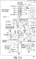
- FIG. 13 is a block diagram of an integrated circuit capable of realizing the interface apparatus, 84.
- the integrated circuit 198 has been specifically designed to serve the role of the interconnection apparatus, thus it may be referred to as an Application Specific Integrated Circuit (ASIC).
- ASIC Application Specific Integrated Circuit
- This ASIC is specifically designed to provide the functionality of the interconnection apparatus 83.
- the term ASIC includes a standard integrated circuit designed to function as the interface apparatus.
- IC integrated circuit
- ASICs application specific integrated circuit
- hybrid ICs low temperature co-fired ceramic (LTCC) hybrid ICs
- MCMs multi-chip modules
- SiP system in a package
- Hybrid ICs are miniaturized electronic circuits that provide the same functionality as a (monolithic) IC.
- MCMs comprise at least two ICs; the interface apparatus of the present invention may be realized by a MCM where the required functionalities are divided between multiple ICs.
- a SiP also known as a Chip Stack MCM is a number of ICs enclosed in a single package or module.
- a SiP can be utilized in the current invention similarly to a MCM.
- programmable logic devices might be used to realize the interface apparatus of the present invention.
- programmable logic devices such as field programmable gate arrays (FPGAs)
- FPGAs field programmable gate arrays
- Fig. 13 depicts a block diagram of a pin driver ASIC 198.
- the microprocessor 80 of Figs. 6 & 7 can command the ASIC 198 to perform the functions of the circuits of interconnection apparatus 83.
- the circuitry of Fig. 13 appears different from the interconnection apparatus 83, the ASIC 198 is capable of performing the same or similar required functions.
- Fig. 6 is a somewhat idealized diagram intended to convey the essence of the module of the invention
- Fig. 13 contains more of the circuit elements that one would place inside an ASIC. Nonetheless, Fig. 13 implements all the circuit elements of Fig. 6 .
- Fig. 6 is a somewhat idealized diagram intended to convey the essence of the module of the invention
- Fig. 13 contains more of the circuit elements that one would place inside an ASIC. Nonetheless, Fig. 13 implements all the circuit elements of Fig. 6 .
- Fig. 6 is a somewhat idealized diagram intended to convey the essence of the module of the invention
- Fig. 13
- FIG. 6 shows a digital-to-analog converter (D/A or DAC) connectable to the device communication connector 16.
- D/A or DAC digital-to-analog converter
- the digital-to-analog converter 226 is connected to the output pin 208 via the switch 220.
- the present invention also includes other circuit arrangements for an ASIC 198 for the same or similar purpose. Those skilled in the art will know how to design various such circuitry, and these are to be included in the present invention.
- Power may be applied to pin 208 by closing high current switch 222b and setting the supply selector 227 to any of the available power supply voltages such as 24-volts, 12-volts, 5-volts, ground or negative 12-volts. Said available power supply voltages provide the required pull-in and sustaining voltage levels to drive the solenoid.
- the ASIC can measure the voltage on pin 208 by closing the low current switch 222 and reading the voltage converted by the analog-to-digital converter 216.
- the ASIC can measure the current supplied to pin 208 by way of the high current switch 222b by use of the multiple programmable current limiters 224 which contain current measurement apparatuses. Said current measurement is used to determine the solenoid inductance as well as to determine whether said solenoid coil is shorted or open.
- the periodic variation in voltage to the solenoid which is used to determine solenoid inductance is most easily accomplished by slightly varying the voltage of the plurality of power supplies 81, said appropriate power supply being selected by supply selector 227.
- the step change in voltage to the solenoid which is used to determine solenoid inductance is most easily accomplished by momentarily changing the supply selector 227 to increase or decrease the solenoid voltage in order to increase or decrease the solenoid current in order to effect the measurement of solenoid inductance.
- ASIC 198 has the ability to measure the amount of current flowing in or out of the node 208 labeled "Pin" in Fig. 13 .
- the pin driver circuit 198 uses its A/D converter 216 to measure current flowing into or out of the pin node 208, thereby enabling the detection of excessive current, or detecting whether a device connected to the Pin node 208 is functioning or wired correctly.
- ASIC 198 also has the ability to monitor the current flow into and out of the pin node 208 to unilaterally disconnect the circuit 198, thereby protecting the ASIC 198 from damage from short circuits or other potentially damaging conditions.
- the ASIC 198 employs a so-called "abuse detect circuit" 218 to monitor rapid changes in current that could potentially damage the ASIC 198.
- Low current switches 220, 221 and 222 and high current switch 222b respond to the abuse detect circuit 218 to disconnect the pin 208.
- the ASIC 198 abuse detect circuit 218 has the ability to establish a current limit for the pin 208, the current limit being programmatically set by the microprocessor 80. This is indicated by selections 224.
- the ASIC 198 can measure the voltage at the pin node 208 in order to allow the microprocessor 80 to determine the state of a digital input connected to the pin node.
- the threshold of a digital input can thereby be programmed rather than being fixed in hardware.
- the threshold of the digital input is set by the microprocessor 80 using the digital-to-analog converter 226.
- the output of the digital-to-analog converter 226 is applied to one side of a latching comparator 225.
- the other input to the latching comparator 225 is routed from the pin 208 and represents the digital input. Therefore, when the voltage of the digital input on the pin 208 crosses the threshold set by the digital-to-analog converter, the microprocessor 80 is able to determine the change in the input and thus deduce that the digital input has changed state.
- the ASIC 198 can measure a current signal presented at the pin node, the current signal being produced by various industrial control devices.
- the ASIC 198 can measure signals varying over the standard 4-20mA and 0-20mA ranges. This current measurement means is accomplished by the microprocessor 80 as it causes the selectable gain voltage buffer 231 to produce a convenient voltage such as zero volts at its output terminal. At the same time, the microprocessor 80 causes the selectable source resistor 228 to present a resistance to the path of current from the industrial control device and its current output. This current enters the ASIC 198 via the pin 208.
- the imposed voltage on one side of a known resistance will cause the unknown current from the external device to produce a voltage on the pin 208 which is then measured via the analog-to-digital converter 216 through the low current switch 222.
- the microprocessor 80 uses Ohm's Law to solve for the unknown current being generated by the industrial control device.
- the ASIC 198 includes functions as described above in reference to the interface apparatus 84.
- an ASIC 198 can include an interconnection apparatus 83 including a digital-to-analog converter 226, wherein the microprocessor 80 is programmable to direct the reception of a digital signal from the microprocessor 80 and cause the signal to be converted by the digital-to-analog converter 226 to an analog signal, and to place a copy of the analog signal on the pin 208. See FIGS. 6 and 13 .
- the ASIC 198 can also include an interconnection apparatus 83 including an analog-to-digital converter 216, and wherein the microprocessor 80 is programmable to detect an analog signal on any selected contact 16 and cause the analog-to-digital converter 216 to convert the signal to a digital signal and output a copy of the digital signal to the microprocessor 80.
- the ASIC 198 can also include a supply selector 227, and a high current switch 222b positioned between the selector 227 and the pin 208.
- the microprocessor 80 is programmable to operate a supply selector 227 to cause a power supply voltage to be connected to a first contact 16, and to cause a power supply return to be connected to a second contact 16.
- a 2x8 cross-point switch 210 that serves to connect a sensor to two adjacent pins 208 which are in turn connected to two adjacent device communication connectors 16.
- the cross-point switch 210 allows a sensor such as a thermocouple to be connected to a precision differential amplifier 212.
- the precision differential amplifier 212 may be connected via the low current switch 222 and the 2x8 cross-point switch 210 to the 4-way cross-point I/O 214 and then to another 4-way cross-point I/O 214 on an adjacent integrated circuit 19 (the integrated circuit for an adjacent contact 16).
- modules 15 can perform independent control of devices connected to the module 15. If, for example, a solenoid is connected to the module 15, then the microprocessor 80 can perform the required periodic or continuous measurement of inductance by causing the solenoid voltage to slightly vary and then measure the resulting current using the current measurement apparatuses in the programmable current limiters 224. In addition, said microprocessor 80 can perform the required steps to shut down the solenoid by throttling or recirculating the current. The module 15 can thereby perform all the functions required to actuate a solenoid and verify its state, whether sealed or open.
- the microprocessor 80 is generally configured/programmed by a controller 85 to receive instruction from the controller as required to sense a particular state of a selected device such as solenoid inductance and/or actuate a selected device, such as solenoid 10, and provide the corresponding data to the system controller.
- the microprocessor 80 may also be programmed/directed by the controller to cause a particular signal to be applied to any selected one or more contacts 16.
- the microprocessor 80 is programmed to respond to direction to send a selected signal type from one or more of devices to the system controller.
- the microprocessor controls the configuration of the interface apparatus 84 and generally the microprocessor is controlled by the system controller.
- the interface apparatus can be configured in response to a message stored in the memory of the microprocessor 80 of the module 15.
- the microprocessor 80 has an embedded web server.
- a personal computer may be connected to the module 15 using an Ethernet cable or a wireless communication device and then to the Internet.
- the personal computer may also be a system controller.
- the embedded web server provides configuration pages for each device connected to the module 15. The user then uses a mouse, or other keyboard inputs, to configure the device function and assign input/output pins. The user may simply drag and drop icons on the configuration page to determine a specific interconnection apparatus for each of the contacts.
- the microprocessor 80 uses a network connection to access a server on the Internet and receive from said server instructions to determine a specific interconnection apparatus for each of the contacts.
- the microprocessor 80 may be programmed to recognize particular input data, included for example in an Ethernet packet on a network cable connected to said microprocessor containing instructions to actuate a particular solenoid connected to said module 15.
- the circuit switching apparatus (R1-R12) are shown diagrammatically as electromechanical relays.
- this switching apparatus is realized in a semiconductor circuit. ( See FIG. 13 and related description.)
- a semiconductor circuit can be realized far less expensively and can act faster than an electromechanical relay circuit.
- An electromechanical relay is used in order to show the essence of the invention.
Landscapes
- Physics & Mathematics (AREA)
- Electromagnetism (AREA)
- Engineering & Computer Science (AREA)
- Power Engineering (AREA)
- Electromagnets (AREA)
- Relay Circuits (AREA)
- Measurement Of Resistance Or Impedance (AREA)
- Magnetically Actuated Valves (AREA)
Claims (12)
- Verfahren zum Betreiben mehrerer Solenoide unter der Verwendung eines konfigurierbaren konfektionierten Eingabe-/Ausgabe-Moduls (15), das mit den Spulen der Solenoide elektrisch verbunden ist, aufweisend die folgenden Schritte:a) in Reaktion darauf, dass ein Solenoid-Ansteuerungssignal wahr wird, Anlegen einer Betätigungsspannung und Aufbauen eines Betätigungsstroms an die Spule durch das Modul (15), wobei die Betätigungsspannung und der Betätigungsstrom dazu führen, dass das Solenoid schließt oder dichtet;b) nach dem Schließen oder Dichten des Solenoids, Ändern auf eine Haltespannung und einen Haltestrom an der Spule durch das Modul (15), wobei die Haltespannung oder der Haltestrom kleiner als die Betätigungsspannung bzw. der Betätigungsstrom sind und das Solenoid in einer geschlossenen oder gedichteten Position halten; undc) Beibehalten der Haltespannung und des Haltestroms durch das Modul (15);wobei ein beliebiger Kontakt (16) der Gerätekommunikations-Verbindungsvorrichtung für eine große Vielzahl verschiedener elektrischer Funktionen konfiguriert sein kann, wie Messen einer Spannung, Erzeugen einer Spannung, Messen eines Stroms, Erzeugen eines Stroms, Erzeugen verschiedener Leistungspegel und sogar Handhaben von Frequenzinformationen, wie zum Beispiel serieller Kommunikationsdaten.
wobei das Modul (15) aufweist:i) eine Gerätekommunikations-Verbindungsvorrichtung zum Anschließen mindestens eines Leiters zwischen dem Modul und jedem der Solenoide,ii) eine Schnittstellenvorrichtung (84), um zu bewirken, dass das Modul (15) ein beliebiges von mehreren Signalen an einen beliebigen von mehreren Kontakten (16) der Gerätekommunikations-Verbindungsvorrichtung anlegt,iii) mindestens eine Leistungsversorgung (81) zum Vorsorgen der Solenoide mit Leistung, undiv) einen Mikroprozessor (80), um das Modul (15) dazu zu veranlassen, ein beliebiges von mehreren Signalen an einen beliebigen von mehreren Kontakten (16) der Gerätekommunikations-Verbindungsvorrichtung anzulegen; - Verfahren gemäß Anspruch 1, wobei das Ändern Folgendes beinhaltet:Trennen der Betätigungsspannung und des Betätigungsstroms von dem Solenoid und Anlegen der Haltespannung und des Haltestroms an das Solenoid durch das Modul (15); oderÄndern des Spannungs- oder Strompegels einer einzigen Leistungsversorgung.
- Verfahren gemäß Anspruch 1, wobei die Haltespannung und der Haltestrom kleiner als fünfzig Prozent der Betätigungsspannung bzw. des Betätigungsstroms betragen.
- Verfahren gemäß Anspruch 1, ferner aufweisend Wegnehmen von Leistung von dem Solenoid, wenn das Solenoid-Ansteuerungssignal falsch wird;
wobei das Verfahren vorzugsweise ferner umfasst: Drosseln des Spulenstroms und Klemmen der Spulenspannung mit dem Modul (15);
wobei das Drosseln vorzugsweise fortgeführt wird, bis die Spannung, die die Spule fähig ist zu beziehen, auf einen Wert fällt, der kleiner als die geklemmte Spannung ist;
wobei das Verfahren vorzugsweise ferner umfasst: nach dem Drosseln, Verbinden der Spule mit einer festen Transistoransteuerung durch das Modul zum Ableiten verbleibender Energie von der Spule. - Verfahren gemäß Anspruch 1, ferner aufweisend: Entfernen von Leistung von dem Solenoid, wenn das Solenoid-Ansteuerungssignal falsch wird;
wobei das Modul (15) durch Verbinden beider Seiten des Solenoids mit derselben Leistungsversorgung, entweder hohe Seite oder niedrige Seite, einen leitfähigen Pfad zum Ableiten von Energie von der Spule bereitstellt. - Verfahren gemäß Anspruch 1, ferner aufweisend: Bestimmen des Zustands des Solenoids durch das Modul (15), wobei der Zustand einen Bereich von Zuständen von offen bis geschlossen oder gedichtet beinhaltet.
- Verfahren gemäß Anspruch 6, wobei das Bestimmen ein Messen der Induktivität der Spule durch das Modul (15) beinhaltet.
- Verfahren gemäß Anspruch 7, wobei:das Bestimmen ein Messen der Induktivität, wenn das Solenoid offen ist, ein Messen der Induktivität, wenn das Solenoid geschlossen oder gedichtet ist, und ein Speichern der Messungen in einem Speicher eines Mikroprozessors des Moduls (15) beinhaltet;das Messen kontinuierlich oder periodisch ist;das Messen beinhaltet: Anlegen eines sinusförmigen Spannungssignals an die Spule durch das Modul (15) und Messen der relativen Größenordnung und relativen Phase des Spulenstroms durch das Modul (15) in Reaktion auf die angelegte sinusförmige Spannung;das Messen beinhaltet: Anlegen eines Rechteck-Spannungssignals an die Spule durch das Modul (15) und Messen der relativen Größenordnung und relativen Phase des Spulenstroms durch das Modul (15) in Reaktion auf die angelegte Rechteck-Spannung; oderdas Messen beinhaltet: Anlegen einer Reihe von Impulsen an die Spule durch das Modul, Messen der Sprungantworten des Spulenstroms über die Zeit durch das Modul in Reaktion auf die angelegten Spannungsimpulse und Berechnen der Induktivität aus den Sprungantworten.
- Verfahren gemäß Anspruch 6, ferner aufweisend ein kontinuierliches oder periodisches Bestimmen des Zustands des Solenoids, wenn das Solenoid-Ansteuerungssignal wahr oder falsch ist;
wobei das Verfahren vorzugsweise ferner aufweist: wenn bestimmt wird, dass das Solenoid nicht geschlossen oder gedichtet ist, Wiederholen des Verbindens, Beibehaltens der Betätigungsspannung und des Betätigungsstroms, Änderns, und Beibehaltens der Haltespannung und des Haltestroms;
wobei die Haltespannung oder der Haltestrom vorzugsweise während des Wiederholens erhöht werden. - Verfahren gemäß Anspruch 1, wobei die Schnittstellenvorrichtung (84) mindestens eine integrierte Schaltung aufweist, die für einen bestimmten der Kontakte eine auswählbare Verbindungsvorrichtung bereitstellt; wobei die integrierte Schaltung vorzugsweise eine ASIC ist.
- Konfigurierbares konfektioniertes Eingabe-/Ausgabe-Modul (15) zum Betreiben mehrerer Solenoide, wobei das Modul (15) aufweist:i) eine Gerätekommunikations-Verbindungsvorrichtung zum Anschließen mindestens eines Leiters zwischen dem Modul und jedem der Solenoiden,ii) eine Schnittstellenvorrichtung (84), um das Modul (15) dazu zu veranlassen, ein beliebiges von mehreren Signalen an einen beliebigen von mehreren Kontakten (16) der Gerätekommunikations-Verbindungsvorrichtung anzulegen,iii) mindestens eine Leistungsversorgung zum Vorsorgen der Solenoide mit Leistung, undiv) einen Speicher zum Speichern eines Computerprogramms und einen Prozessor (80) zum Ausführen des Programms, wobei das Programm den Prozessor veranlasst, Folgendes auszuführen:wobei ein beliebiger Kontakt (16) der Gerätekommunikations-Verbindungsvorrichtung für eine große Vielzahl verschiedener elektrischer Funktionen konfiguriert sein kann, wie Messen einer Spannung, Erzeugen einer Spannung, Messen eines Stroms, Erzeugen eines Stroms, Erzeugen verschiedener Leistungspegel und sogar Handhaben von Frequenzinformationen, wie zum Beispiel serieller Kommunikationsdaten.a) in Reaktion darauf, dass ein Solenoid-Ansteuerungssignal wahr wird, Anlegen einer Betätigungsspannung und Aufbauen eines Betätigungsstroms an die Spule durch das Modul, wobei die Betätigungsspannung und der Betätigungsstrom dazu führen, dass das Solenoid schließt oder dichtet;b) nach dem Schließen oder Dichten des Solenoids, Ändern auf eine Haltespannung und einen Haltestrom an der Spule durch das Modul, wobei die Haltespannung oder der Haltestrom kleiner als die Betätigungsspannung bzw. der Betätigungsstrom sind und das Solenoid in einer geschlossenen oder gedichteten Position halten; undc) Beibehalten der Haltespannung und des Haltestroms durch das Modul;
- Modul gemäß Anspruch 11, wobei das Programm den Prozessor veranlasst, die Induktivität der Spule durch das Modul (15) zu messen, um den Zustand des Solenoids zu bestimmen, wobei der Zustand einen Bereich von Zuständen von offen bis geschlossen oder gedichtet beinhaltet.
Applications Claiming Priority (2)
| Application Number | Priority Date | Filing Date | Title |
|---|---|---|---|
| US40641410P | 2010-10-25 | 2010-10-25 | |
| PCT/US2011/057766 WO2012058245A1 (en) | 2010-10-25 | 2011-10-25 | Configurable solenoid actuation method and apparatus |
Publications (3)
| Publication Number | Publication Date |
|---|---|
| EP2633539A1 EP2633539A1 (de) | 2013-09-04 |
| EP2633539A4 EP2633539A4 (de) | 2014-12-24 |
| EP2633539B1 true EP2633539B1 (de) | 2017-06-14 |
Family
ID=45994362
Family Applications (1)
| Application Number | Title | Priority Date | Filing Date |
|---|---|---|---|
| EP11836970.1A Active EP2633539B1 (de) | 2010-10-25 | 2011-10-25 | Verfahren und vorrichtung zur betätigung eines konfigurierbaren elektromagneten |
Country Status (6)
| Country | Link |
|---|---|
| EP (1) | EP2633539B1 (de) |
| JP (1) | JP6305061B2 (de) |
| CN (1) | CN103354943B (de) |
| DK (1) | DK2633539T3 (de) |
| ES (1) | ES2639089T3 (de) |
| WO (1) | WO2012058245A1 (de) |
Families Citing this family (2)
| Publication number | Priority date | Publication date | Assignee | Title |
|---|---|---|---|---|
| CN104483883B (zh) * | 2014-12-25 | 2017-04-05 | 南京因泰莱电器股份有限公司 | 一种继电器控制单元 |
| CN121034905B (zh) * | 2025-10-30 | 2026-02-27 | 深圳天邦达数字能源股份有限公司 | 一种汽车继电器节能控制方法及系统 |
Family Cites Families (21)
| Publication number | Priority date | Publication date | Assignee | Title |
|---|---|---|---|---|
| JPH0629829B2 (ja) * | 1989-06-07 | 1994-04-20 | 矢崎総業株式会社 | ソレノイドの動作状態検出装置 |
| JP2582460B2 (ja) * | 1990-05-24 | 1997-02-19 | 矢崎総業株式会社 | ソレノイドの動作状態検出装置 |
| JP2695698B2 (ja) * | 1990-11-27 | 1998-01-14 | 株式会社トキメック | ソレノイドの可動鉄心位置チエツク方法 |
| JP2998355B2 (ja) * | 1991-11-15 | 2000-01-11 | 松下電器産業株式会社 | ガス遮断弁装置 |
| US5497653A (en) * | 1992-09-21 | 1996-03-12 | General Electric Company | Method and system for detecting significant hydraulic leaks |
| JPH1047138A (ja) * | 1996-08-01 | 1998-02-17 | Hitachi Ltd | 電磁アクチュエータの可動子の位置検出装置とその検出方法,内燃機関の吸入空気量制御装置とその制御方法及び自動車用アクチュエータの診断方法 |
| US5784245A (en) * | 1996-11-27 | 1998-07-21 | Motorola Inc. | Solenoid driver and method for determining solenoid operational status |
| JPH1145403A (ja) * | 1997-07-29 | 1999-02-16 | Olympus Optical Co Ltd | カメラの磁気ヘッド回路 |
| US6657847B1 (en) * | 1999-07-13 | 2003-12-02 | Siemens Automotive Corporation | Method of using inductance for determining the position of an armature in an electromagnetic solenoid |
| DE10003531A1 (de) | 1999-12-16 | 2001-07-05 | Siemens Ag | Verfahren zum Schalten einer induktiven Last |
| DE50006237D1 (de) * | 1999-12-16 | 2004-06-03 | Siemens Ag | Verfahren zum Schalten einer Last |
| SE518378C2 (sv) * | 2000-05-12 | 2002-10-01 | Macab Ab | Kommunikationsenhet för datanätsacces via kabeltevenät |
| US7216191B2 (en) * | 2001-02-14 | 2007-05-08 | Berkeley Process Control, Inc. | System for programmed control of signal input and output to and from cable conductors |
| US6850402B2 (en) * | 2002-03-01 | 2005-02-01 | Honeywell International Inc. | Circuit and method for controlling current flow through a solenoid |
| ITTO20030938A1 (it) * | 2003-11-25 | 2005-05-26 | Fiat Ricerche | Dispositivo di comando di elettroattuatori induttivi. |
| EP1832945A1 (de) * | 2006-03-07 | 2007-09-12 | S-Rain Control A/S | System und Verfahren zur Optimierung und Zufuhr von Energie für einen Ventileinsatz |
| JP4600370B2 (ja) * | 2006-09-06 | 2010-12-15 | 株式会社デンソー | 電磁弁駆動装置 |
| JP4698562B2 (ja) * | 2006-11-30 | 2011-06-08 | リンナイ株式会社 | モータ安全弁の制御方法 |
| JP4915332B2 (ja) * | 2007-11-28 | 2012-04-11 | トヨタ自動車株式会社 | 電磁アクチュエータの制御装置 |
| JP5076839B2 (ja) * | 2007-11-28 | 2012-11-21 | トヨタ自動車株式会社 | 電磁アクチュエータ制御装置及び方法 |
| DE102008023626B4 (de) * | 2008-05-15 | 2016-11-10 | Infineon Technologies Ag | Relaissteuerung zur Steuerung eines Erregerstromes eines Relais |
-
2011
- 2011-10-25 ES ES11836970.1T patent/ES2639089T3/es active Active
- 2011-10-25 JP JP2013536755A patent/JP6305061B2/ja not_active Expired - Fee Related
- 2011-10-25 EP EP11836970.1A patent/EP2633539B1/de active Active
- 2011-10-25 CN CN201180062384.4A patent/CN103354943B/zh active Active
- 2011-10-25 WO PCT/US2011/057766 patent/WO2012058245A1/en not_active Ceased
- 2011-10-25 DK DK11836970.1T patent/DK2633539T3/en active
Also Published As
| Publication number | Publication date |
|---|---|
| EP2633539A4 (de) | 2014-12-24 |
| CN103354943B (zh) | 2019-12-03 |
| JP6305061B2 (ja) | 2018-04-04 |
| DK2633539T3 (en) | 2017-09-18 |
| CN103354943A (zh) | 2013-10-16 |
| ES2639089T3 (es) | 2017-10-25 |
| WO2012058245A1 (en) | 2012-05-03 |
| JP2013544026A (ja) | 2013-12-09 |
| EP2633539A1 (de) | 2013-09-04 |
Similar Documents
| Publication | Publication Date | Title |
|---|---|---|
| US9013854B2 (en) | Configurable solenoid actuation method and apparatus | |
| JP5920909B2 (ja) | Pwm制御により双方向サーボアクチュエータを制御するためのシステム、方法、及び装置 | |
| CN101436048B (zh) | 具有基于微机电系统的切换的可编程逻辑控制器 | |
| JP4987119B2 (ja) | ブラシレスモータ装置及び制御装置 | |
| CN106164788B (zh) | 用于模仿三相无刷直流电机的方法和仿真器控制器 | |
| JPS61250310A (ja) | 内燃機関におけるガス交換弁の制御方法及び装置 | |
| EP0184940B1 (de) | Verfahren und Einrichtung zur Steuerung elektromagnetischer Stellglieder | |
| US11651918B2 (en) | Sensing properties of switching devices using back EMF measurements | |
| DK2633539T3 (en) | Method and apparatus for configurable actuation of a solenoid | |
| JP2011248883A (ja) | Hブリッジをヒステリシス制御とともに使用して双方向サーボアクチュエータを制御するためのシステム、方法、及び装置 | |
| CN100480709C (zh) | 阀门的电流量控制 | |
| JP2011248881A (ja) | 高効率サーボアクチュエータ及び励磁ドライバを実現するためのシステム、方法、及び装置 | |
| JP2011253532A (ja) | 双方向ヒステリシス制御を使用してアクチュエータ駆動電流を制御するためのシステム、方法、及び装置 | |
| CN113517675B (zh) | 用于控制接触器打开时间的系统及方法 | |
| Serrano-Seco et al. | An audio-based iterative controller for soft landing of electromechanical relays | |
| EP3944267B1 (de) | Detektion der position eines ankers in einem elektromagnetischen aktuator | |
| Fiene et al. | Toward switching motor control | |
| Fiene et al. | Switching motor control: An integrated amplifier design for improved velocity estimation and feedback | |
| TW202445301A (zh) | 電磁閥的控制電路 | |
| JP2586279Y2 (ja) | 電磁弁制御回路の故障検出装置 | |
| KR100603529B1 (ko) | 솔레노이드 코일 구동 회로 | |
| JP2000323325A (ja) | アクチュエータ制御用回路 | |
| JPH10208575A (ja) | リレー制御方法 | |
| JPH05304022A (ja) | 電磁石装置の駆動回路 | |
| Govindarajan et al. | Servo control of solenoid actuators using augmented feedback linearization |
Legal Events
| Date | Code | Title | Description |
|---|---|---|---|
| PUAI | Public reference made under article 153(3) epc to a published international application that has entered the european phase |
Free format text: ORIGINAL CODE: 0009012 |
|
| 17P | Request for examination filed |
Effective date: 20130417 |
|
| AK | Designated contracting states |
Kind code of ref document: A1 Designated state(s): AL AT BE BG CH CY CZ DE DK EE ES FI FR GB GR HR HU IE IS IT LI LT LU LV MC MK MT NL NO PL PT RO RS SE SI SK SM TR |
|
| DAX | Request for extension of the european patent (deleted) | ||
| REG | Reference to a national code |
Ref country code: DE Ref legal event code: R079 Ref document number: 602011038789 Country of ref document: DE Free format text: PREVIOUS MAIN CLASS: H01H0047280000 Ipc: H01F0007180000 |
|
| A4 | Supplementary search report drawn up and despatched |
Effective date: 20141126 |
|
| RIC1 | Information provided on ipc code assigned before grant |
Ipc: H01H 47/32 20060101ALI20141120BHEP Ipc: H01H 47/22 20060101ALI20141120BHEP Ipc: H01F 7/18 20060101AFI20141120BHEP |
|
| 17Q | First examination report despatched |
Effective date: 20160324 |
|
| GRAP | Despatch of communication of intention to grant a patent |
Free format text: ORIGINAL CODE: EPIDOSNIGR1 |
|
| INTG | Intention to grant announced |
Effective date: 20160818 |
|
| RIN1 | Information on inventor provided before grant (corrected) |
Inventor name: BOTHA, MAURITZ Inventor name: BRASFIELD, LARRY Inventor name: SAGUES, PAUL |
|
| GRAJ | Information related to disapproval of communication of intention to grant by the applicant or resumption of examination proceedings by the epo deleted |
Free format text: ORIGINAL CODE: EPIDOSDIGR1 |
|
| GRAP | Despatch of communication of intention to grant a patent |
Free format text: ORIGINAL CODE: EPIDOSNIGR1 |
|
| INTC | Intention to grant announced (deleted) | ||
| INTG | Intention to grant announced |
Effective date: 20170110 |
|
| GRAS | Grant fee paid |
Free format text: ORIGINAL CODE: EPIDOSNIGR3 |
|
| GRAA | (expected) grant |
Free format text: ORIGINAL CODE: 0009210 |
|
| AK | Designated contracting states |
Kind code of ref document: B1 Designated state(s): AL AT BE BG CH CY CZ DE DK EE ES FI FR GB GR HR HU IE IS IT LI LT LU LV MC MK MT NL NO PL PT RO RS SE SI SK SM TR |
|
| REG | Reference to a national code |
Ref country code: GB Ref legal event code: FG4D |
|
| REG | Reference to a national code |
Ref country code: CH Ref legal event code: EP Ref country code: AT Ref legal event code: REF Ref document number: 901683 Country of ref document: AT Kind code of ref document: T Effective date: 20170615 |
|
| REG | Reference to a national code |
Ref country code: IE Ref legal event code: FG4D |
|
| REG | Reference to a national code |
Ref country code: DE Ref legal event code: R096 Ref document number: 602011038789 Country of ref document: DE |
|
| REG | Reference to a national code |
Ref country code: CH Ref legal event code: NV Representative=s name: ISLER AND PEDRAZZINI AG, CH |
|
| REG | Reference to a national code |
Ref country code: DK Ref legal event code: T3 Effective date: 20170912 Ref country code: FR Ref legal event code: PLFP Year of fee payment: 7 |
|
| REG | Reference to a national code |
Ref country code: NL Ref legal event code: FP |
|
| REG | Reference to a national code |
Ref country code: SE Ref legal event code: TRGR |
|
| REG | Reference to a national code |
Ref country code: LT Ref legal event code: MG4D Ref country code: ES Ref legal event code: FG2A Ref document number: 2639089 Country of ref document: ES Kind code of ref document: T3 Effective date: 20171025 |
|
| PG25 | Lapsed in a contracting state [announced via postgrant information from national office to epo] |
Ref country code: FI Free format text: LAPSE BECAUSE OF FAILURE TO SUBMIT A TRANSLATION OF THE DESCRIPTION OR TO PAY THE FEE WITHIN THE PRESCRIBED TIME-LIMIT Effective date: 20170614 Ref country code: HR Free format text: LAPSE BECAUSE OF FAILURE TO SUBMIT A TRANSLATION OF THE DESCRIPTION OR TO PAY THE FEE WITHIN THE PRESCRIBED TIME-LIMIT Effective date: 20170614 Ref country code: NO Free format text: LAPSE BECAUSE OF FAILURE TO SUBMIT A TRANSLATION OF THE DESCRIPTION OR TO PAY THE FEE WITHIN THE PRESCRIBED TIME-LIMIT Effective date: 20170914 Ref country code: GR Free format text: LAPSE BECAUSE OF FAILURE TO SUBMIT A TRANSLATION OF THE DESCRIPTION OR TO PAY THE FEE WITHIN THE PRESCRIBED TIME-LIMIT Effective date: 20170915 Ref country code: LT Free format text: LAPSE BECAUSE OF FAILURE TO SUBMIT A TRANSLATION OF THE DESCRIPTION OR TO PAY THE FEE WITHIN THE PRESCRIBED TIME-LIMIT Effective date: 20170614 |
|
| PG25 | Lapsed in a contracting state [announced via postgrant information from national office to epo] |
Ref country code: LV Free format text: LAPSE BECAUSE OF FAILURE TO SUBMIT A TRANSLATION OF THE DESCRIPTION OR TO PAY THE FEE WITHIN THE PRESCRIBED TIME-LIMIT Effective date: 20170614 Ref country code: RS Free format text: LAPSE BECAUSE OF FAILURE TO SUBMIT A TRANSLATION OF THE DESCRIPTION OR TO PAY THE FEE WITHIN THE PRESCRIBED TIME-LIMIT Effective date: 20170614 Ref country code: BG Free format text: LAPSE BECAUSE OF FAILURE TO SUBMIT A TRANSLATION OF THE DESCRIPTION OR TO PAY THE FEE WITHIN THE PRESCRIBED TIME-LIMIT Effective date: 20170914 |
|
| PG25 | Lapsed in a contracting state [announced via postgrant information from national office to epo] |
Ref country code: SK Free format text: LAPSE BECAUSE OF FAILURE TO SUBMIT A TRANSLATION OF THE DESCRIPTION OR TO PAY THE FEE WITHIN THE PRESCRIBED TIME-LIMIT Effective date: 20170614 Ref country code: EE Free format text: LAPSE BECAUSE OF FAILURE TO SUBMIT A TRANSLATION OF THE DESCRIPTION OR TO PAY THE FEE WITHIN THE PRESCRIBED TIME-LIMIT Effective date: 20170614 Ref country code: RO Free format text: LAPSE BECAUSE OF FAILURE TO SUBMIT A TRANSLATION OF THE DESCRIPTION OR TO PAY THE FEE WITHIN THE PRESCRIBED TIME-LIMIT Effective date: 20170614 Ref country code: CZ Free format text: LAPSE BECAUSE OF FAILURE TO SUBMIT A TRANSLATION OF THE DESCRIPTION OR TO PAY THE FEE WITHIN THE PRESCRIBED TIME-LIMIT Effective date: 20170614 |
|
| PG25 | Lapsed in a contracting state [announced via postgrant information from national office to epo] |
Ref country code: SM Free format text: LAPSE BECAUSE OF FAILURE TO SUBMIT A TRANSLATION OF THE DESCRIPTION OR TO PAY THE FEE WITHIN THE PRESCRIBED TIME-LIMIT Effective date: 20170614 Ref country code: IS Free format text: LAPSE BECAUSE OF FAILURE TO SUBMIT A TRANSLATION OF THE DESCRIPTION OR TO PAY THE FEE WITHIN THE PRESCRIBED TIME-LIMIT Effective date: 20171014 Ref country code: PL Free format text: LAPSE BECAUSE OF FAILURE TO SUBMIT A TRANSLATION OF THE DESCRIPTION OR TO PAY THE FEE WITHIN THE PRESCRIBED TIME-LIMIT Effective date: 20170614 |
|
| REG | Reference to a national code |
Ref country code: DE Ref legal event code: R097 Ref document number: 602011038789 Country of ref document: DE |
|
| PLBE | No opposition filed within time limit |
Free format text: ORIGINAL CODE: 0009261 |
|
| STAA | Information on the status of an ep patent application or granted ep patent |
Free format text: STATUS: NO OPPOSITION FILED WITHIN TIME LIMIT |
|
| 26N | No opposition filed |
Effective date: 20180315 |
|
| PG25 | Lapsed in a contracting state [announced via postgrant information from national office to epo] |
Ref country code: MC Free format text: LAPSE BECAUSE OF FAILURE TO SUBMIT A TRANSLATION OF THE DESCRIPTION OR TO PAY THE FEE WITHIN THE PRESCRIBED TIME-LIMIT Effective date: 20170614 |
|
| PG25 | Lapsed in a contracting state [announced via postgrant information from national office to epo] |
Ref country code: LU Free format text: LAPSE BECAUSE OF NON-PAYMENT OF DUE FEES Effective date: 20171025 |
|
| REG | Reference to a national code |
Ref country code: BE Ref legal event code: MM Effective date: 20171031 |
|
| PG25 | Lapsed in a contracting state [announced via postgrant information from national office to epo] |
Ref country code: SI Free format text: LAPSE BECAUSE OF FAILURE TO SUBMIT A TRANSLATION OF THE DESCRIPTION OR TO PAY THE FEE WITHIN THE PRESCRIBED TIME-LIMIT Effective date: 20170614 Ref country code: BE Free format text: LAPSE BECAUSE OF NON-PAYMENT OF DUE FEES Effective date: 20171031 |
|
| REG | Reference to a national code |
Ref country code: FR Ref legal event code: PLFP Year of fee payment: 8 |
|
| PG25 | Lapsed in a contracting state [announced via postgrant information from national office to epo] |
Ref country code: MT Free format text: LAPSE BECAUSE OF NON-PAYMENT OF DUE FEES Effective date: 20171025 |
|
| REG | Reference to a national code |
Ref country code: AT Ref legal event code: UEP Ref document number: 901683 Country of ref document: AT Kind code of ref document: T Effective date: 20170614 |
|
| PG25 | Lapsed in a contracting state [announced via postgrant information from national office to epo] |
Ref country code: HU Free format text: LAPSE BECAUSE OF FAILURE TO SUBMIT A TRANSLATION OF THE DESCRIPTION OR TO PAY THE FEE WITHIN THE PRESCRIBED TIME-LIMIT; INVALID AB INITIO Effective date: 20111025 |
|
| PG25 | Lapsed in a contracting state [announced via postgrant information from national office to epo] |
Ref country code: CY Free format text: LAPSE BECAUSE OF NON-PAYMENT OF DUE FEES Effective date: 20170614 |
|
| PG25 | Lapsed in a contracting state [announced via postgrant information from national office to epo] |
Ref country code: MK Free format text: LAPSE BECAUSE OF FAILURE TO SUBMIT A TRANSLATION OF THE DESCRIPTION OR TO PAY THE FEE WITHIN THE PRESCRIBED TIME-LIMIT Effective date: 20170614 |
|
| PG25 | Lapsed in a contracting state [announced via postgrant information from national office to epo] |
Ref country code: TR Free format text: LAPSE BECAUSE OF FAILURE TO SUBMIT A TRANSLATION OF THE DESCRIPTION OR TO PAY THE FEE WITHIN THE PRESCRIBED TIME-LIMIT Effective date: 20170614 |
|
| PG25 | Lapsed in a contracting state [announced via postgrant information from national office to epo] |
Ref country code: PT Free format text: LAPSE BECAUSE OF FAILURE TO SUBMIT A TRANSLATION OF THE DESCRIPTION OR TO PAY THE FEE WITHIN THE PRESCRIBED TIME-LIMIT Effective date: 20170614 |
|
| PG25 | Lapsed in a contracting state [announced via postgrant information from national office to epo] |
Ref country code: AL Free format text: LAPSE BECAUSE OF FAILURE TO SUBMIT A TRANSLATION OF THE DESCRIPTION OR TO PAY THE FEE WITHIN THE PRESCRIBED TIME-LIMIT Effective date: 20170614 |
|
| PGFP | Annual fee paid to national office [announced via postgrant information from national office to epo] |
Ref country code: IE Payment date: 20240910 Year of fee payment: 14 |
|
| PGFP | Annual fee paid to national office [announced via postgrant information from national office to epo] |
Ref country code: GB Payment date: 20240905 Year of fee payment: 14 |
|
| PGFP | Annual fee paid to national office [announced via postgrant information from national office to epo] |
Ref country code: FR Payment date: 20240909 Year of fee payment: 14 |
|
| PGFP | Annual fee paid to national office [announced via postgrant information from national office to epo] |
Ref country code: NL Payment date: 20240917 Year of fee payment: 14 |
|
| PGFP | Annual fee paid to national office [announced via postgrant information from national office to epo] |
Ref country code: IT Payment date: 20240910 Year of fee payment: 14 Ref country code: SE Payment date: 20240910 Year of fee payment: 14 |
|
| PGFP | Annual fee paid to national office [announced via postgrant information from national office to epo] |
Ref country code: DE Payment date: 20240904 Year of fee payment: 14 |
|
| PGFP | Annual fee paid to national office [announced via postgrant information from national office to epo] |
Ref country code: DK Payment date: 20241011 Year of fee payment: 14 |
|
| PGFP | Annual fee paid to national office [announced via postgrant information from national office to epo] |
Ref country code: AT Payment date: 20240925 Year of fee payment: 14 |
|
| PGFP | Annual fee paid to national office [announced via postgrant information from national office to epo] |
Ref country code: ES Payment date: 20241104 Year of fee payment: 14 |
|
| PGFP | Annual fee paid to national office [announced via postgrant information from national office to epo] |
Ref country code: CH Payment date: 20241101 Year of fee payment: 14 |