EP3944267B1 - Detektion der position eines ankers in einem elektromagnetischen aktuator - Google Patents
Detektion der position eines ankers in einem elektromagnetischen aktuator Download PDFInfo
- Publication number
- EP3944267B1 EP3944267B1 EP21180356.4A EP21180356A EP3944267B1 EP 3944267 B1 EP3944267 B1 EP 3944267B1 EP 21180356 A EP21180356 A EP 21180356A EP 3944267 B1 EP3944267 B1 EP 3944267B1
- Authority
- EP
- European Patent Office
- Prior art keywords
- armature
- switch
- coil
- current
- measurement
- Prior art date
- Legal status (The legal status is an assumption and is not a legal conclusion. Google has not performed a legal analysis and makes no representation as to the accuracy of the status listed.)
- Active
Links
Images





Classifications
-
- H—ELECTRICITY
- H01—ELECTRIC ELEMENTS
- H01F—MAGNETS; INDUCTANCES; TRANSFORMERS; SELECTION OF MATERIALS FOR THEIR MAGNETIC PROPERTIES
- H01F7/00—Magnets
- H01F7/06—Electromagnets; Actuators including electromagnets
- H01F7/08—Electromagnets; Actuators including electromagnets with armatures
- H01F7/18—Circuit arrangements for obtaining desired operating characteristics, e.g. for slow operation, for sequential energisation of windings, for high-speed energisation of windings
- H01F7/1844—Monitoring or fail-safe circuits
-
- H—ELECTRICITY
- H01—ELECTRIC ELEMENTS
- H01H—ELECTRIC SWITCHES; RELAYS; SELECTORS; EMERGENCY PROTECTIVE DEVICES
- H01H47/00—Circuit arrangements not adapted to a particular application of the relay and designed to obtain desired operating characteristics or to provide energising current
- H01H47/22—Circuit arrangements not adapted to a particular application of the relay and designed to obtain desired operating characteristics or to provide energising current for supplying energising current for relay coil
- H01H47/32—Energising current supplied by semiconductor device
-
- H—ELECTRICITY
- H01—ELECTRIC ELEMENTS
- H01H—ELECTRIC SWITCHES; RELAYS; SELECTORS; EMERGENCY PROTECTIVE DEVICES
- H01H47/00—Circuit arrangements not adapted to a particular application of the relay and designed to obtain desired operating characteristics or to provide energising current
- H01H47/002—Monitoring or fail-safe circuits
-
- H—ELECTRICITY
- H01—ELECTRIC ELEMENTS
- H01H—ELECTRIC SWITCHES; RELAYS; SELECTORS; EMERGENCY PROTECTIVE DEVICES
- H01H50/00—Details of electromagnetic relays
- H01H50/16—Magnetic circuit arrangements
- H01H50/18—Movable parts of magnetic circuits, e.g. armature
-
- H—ELECTRICITY
- H01—ELECTRIC ELEMENTS
- H01F—MAGNETS; INDUCTANCES; TRANSFORMERS; SELECTION OF MATERIALS FOR THEIR MAGNETIC PROPERTIES
- H01F7/00—Magnets
- H01F7/06—Electromagnets; Actuators including electromagnets
- H01F7/08—Electromagnets; Actuators including electromagnets with armatures
- H01F7/18—Circuit arrangements for obtaining desired operating characteristics, e.g. for slow operation, for sequential energisation of windings, for high-speed energisation of windings
- H01F7/1844—Monitoring or fail-safe circuits
- H01F2007/185—Monitoring or fail-safe circuits with armature position measurement
-
- H—ELECTRICITY
- H01—ELECTRIC ELEMENTS
- H01F—MAGNETS; INDUCTANCES; TRANSFORMERS; SELECTION OF MATERIALS FOR THEIR MAGNETIC PROPERTIES
- H01F7/00—Magnets
- H01F7/06—Electromagnets; Actuators including electromagnets
- H01F7/08—Electromagnets; Actuators including electromagnets with armatures
- H01F7/121—Guiding or setting position of armatures, e.g. retaining armatures in their end position
-
- H—ELECTRICITY
- H01—ELECTRIC ELEMENTS
- H01F—MAGNETS; INDUCTANCES; TRANSFORMERS; SELECTION OF MATERIALS FOR THEIR MAGNETIC PROPERTIES
- H01F7/00—Magnets
- H01F7/06—Electromagnets; Actuators including electromagnets
- H01F7/08—Electromagnets; Actuators including electromagnets with armatures
- H01F7/16—Rectilinearly-movable armatures
- H01F7/1607—Armatures entering the winding
- H01F7/1615—Armatures or stationary parts of magnetic circuit having permanent magnet
Definitions
- switching devices are generally used throughout industrial, commercial, material handling, process and manufacturing settings, to mention only a few
- switching device is generally intended to describe any electromechanical switching device, such as mechanical switching devices (e.g., a contactor, a relay, latching relay, air break devices, and controlled atmosphere devices) or solid-state devices (e.g., a silicon-controlled rectifier (SCR)). More specifically, switching devices generally open to disconnect electric power from a load and close to connect electric power to the load. For example, switching devices may connect and disconnect three-phase electric power to an electric motor.
- mechanical switching devices e.g., a contactor, a relay, latching relay, air break devices, and controlled atmosphere devices
- solid-state devices e.g., a silicon-controlled rectifier (SCR)
- SCR silicon-controlled rectifier
- a latching switch may maintain a particular state (e.g., open or closed) independent of power supplied to the latching switch.
- the armature position of the latching switch can change based on a user's interaction (e.g., manual reset) with the latching switch. Regardless of the position (e.g., open or closed) of the armature of the latching switch, it may be desired to detect the position of the armature without physically examining the latching switch.
- US 6 249 418 B1 relates to a system for controlling the force and/or motion of an electromagnetic actuator.
- the actuator could be a solenoid, relay, or levitating device.
- the drive to the coil can be linear or switching, voltage or current and the sensors measuring the system can be as simple as just a current sensor monitoring the coil current or a flux sensor. Continuous control of position can be achieved allowing magnetic levitation or the soft landing of the moving element.
- US 2019/326907 A1 relates to an electrical assembly comprising a device.
- the device includes an inductive coil and an armature.
- the armature is arranged to be moveable between first and second positions when the inductive coil is energized.
- the electrical assembly further includes a detection unit which is configured to detect an inductance of the inductive coil or a characteristic that corresponds to the inductance of the inductive coil.
- the detection unit is further configured to determine the position of the armature based on the detected inductance or the detected characteristic.
- US 2018/080799 A1 relates to a method and system for determining the position of the armature of a solenoid using a controller to determine the temperature of the solenoid and to indirectly determine the position of the armature without the need of an additional sensor using current sensing pulses and a solenoid capable of staying engaged due to residual magnetism after the coil has been de-energized.
- DE 10 2016 220190 A1 relates to a method for pulsed control of a load using an H-bridge circuit.
- JP H10 47140 A relates to a driving device of a fuel injection valve for an internal combustion engine and an injector driving device.
- the object of the invention is to provide an enhanced system for detecting an armature position.
- a system may include an armature configured to move between a first position that electrically couples the armature to a first contact and a second position that electrically couples the armature to a second contact.
- the system may also include a coil configured receive a current, such that the current conducting in the coil is configured to magnetize a core. The magnetized core may cause the armature to move from the first position to the second position.
- the system may also include a control system configured to detect a position of the armature based on an inductance of the coil.
- a method may include sending, via circuitry, a plurality of gate signals to a plurality of switches that may cause the plurality of switches to open.
- the plurality of switches may be part of an H-bridge circuit.
- the method also includes sending, via the circuitry, a first signal to a first switch, such that the first signal is configured to cause the first switch to close.
- the method may then involve sending, via the circuitry, a pulse-width modulated signal to a second switch that is part of the H-bridge circuit and measuring, via the circuitry, a current conducting via the first switch while the pulse-width modulated signal is provided to the second switch.
- the current corresponds to a state of an actuator coil.
- a circuit may include a plurality of switches that may be part of an H-bridge circuit and a coil that may magnetize a core of an actuator based on a current conducting in the coil.
- the circuit may also include a diode configured to couple to the coil, a resistor configured to couple to the diode, and a switch that may couple to the resistor. The switch may close and conduct the current received from the coil.
- switching devices are used in various implementations, such as industrial, commercial, material handling, manufacturing, power conversion, and/or power distribution, to connect and/or disconnect electric power from a load.
- a number of switching devices may be used to control operations, monitor conditions, and perform other operations related to various equipment in an industrial automation system.
- the switching devices may be used to coordinate operations across a number of devices
- the open operation of the switching device generally depends on a coil current and a core flux of a coil that induces a magnetic field in the switching device.
- Some types of switching devices include a latching mechanism that enable the switching device to remain in a particular position (e.g., open or closed) regardless of whether power (e.g., coil current) is present on the switching device.
- the latching switching device can change states when a user interacts with the latching switching device using a manual reset operation or the like.
- a control system or other remote monitoring system may not be aware of the state (e.g., open or closed) change of the latching switching device without the use of position sensors or other hardware components that monitor the position of an armature in the switching device.
- the present embodiments disclosed herein are related to systems and methods for detecting the armature position of a switching device without the use of position sensor hardware. Additional details with regard to determining the armature position of an armature in a switching device will be described below with reference to FIGS. 1-11 .
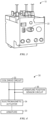
- FIG.1 depicts a latching solenoid 10 in a latched position.
- the latching solenoid 10 may be any suitable switch mechanism or electromagnetic actuator with a latching feature.
- the latching solenoid 10 may include a housing 12, a coil 14, a magnet 16, a spring 18, and an armature 20.
- the coil 14 may be electrically coupled to a power source that provides a current through the coil 14.
- the current in the coil 14 may induce a magnetic field or flux in a core of the armature 20 that interacts with the magnet 16 and causes the spring 18 and the armature 20 to move.
- the armature 20 may be coupled to the spring 18, such that both components move together.
- the latching solenoid 10 may also include a latching mechanism that causes the spring 18, the armature 20, or both to lock or latch into a fixed position.
- FIG. 1 illustrates the spring 18 in a compressed position and the armature 20 pulled into the housing 12 of the latching solenoid 10.
- the latching mechanism may include a hook, a groove, or some suitable mechanical feature that fixes a position of the spring 18 in a compressed orientation.
- the latching solenoid 10 may also be secured to a latched position using the magnet 16
- the armature 20 and the spring 18 is described in a particular configuration (e.g., compressed, inside housing), the armature 20 and the spring 18 may be configured in any suitable arrangement according to a variety of embodiments for implementing the latching solenoid 10.
- the armature 20 moves between positions as shown in FIG. 1 and FIG. 2 .
- the armature 20 includes a first contact that is electrically coupled to a second contact when in a latched position and to a third contact when in a de-latched position based on the movement of the armature 20.
- the latching solenoid 10 may act as a switch or relay controlling an electrical connection between two nodes.
- the magnetic field induced by the current in the coil 14 may cause the spring 18 to compress and fix the armature 20 in a latched position, as shown in FIG. 1 .
- the latching solenoid 10 may be de-latched based on a user input received via a mechanical input device (e.g., button) disposed on the housing 12.
- FIG. 3 illustrates an example of a latching solenoid 10 that includes a button 22 that may be used to latch or de-latch the spring 18 and/or the armature 20.
- the latching solenoid 10 may interface with a number of electrical components, such as low-voltage circuitry, a microcontroller/microprocessor, and the like.
- the button 22 may provide a physical component that a user may access to manually perform operations for the latching solenoid 10 regardless of the current present on the coil 14.
- the button 22 may be a trip or reset button for overload products. For a number of overload products (e.g., overload relays.), power to the latching solenoid 10 may be lost when an overload/trip fault is present.
- the button 22 may be used to maintain a state (e.g., latched or de-latched) of the latching solenoid 10 when left at rest, while allowing for user to be able to modify the position of the armature 20 when pressed independent of the power provided to the latching solenoid 10.
- a state e.g., latched or de-latched
- the latching mechanism that mechanically latches or holds the armature 20 in a particular position after the core magnetizes of the armature 20 magnetizes, thereby causing the armature 20 to change positions.
- the latching mechanism may also be configured to mechanically latch or hold the armature 20 in a particular position after the coil 14 demagnetizes and the armature 20 changes position.
- the latching mechanism may be released via manual interaction by a user, thereby causing the armature 20 to move positions.
- the change in the position of the armature 20 may not be detected by a control system or monitor system without the use of additional sensors that monitor the position of the armature 20. That is, the presence of current or the lack of the current in the coil 14 may not be indicative of whether the armature 20 is in the latched position.
- the embodiments described herein may be used to detect the position of the armature 20 of the latching solenoid 10 without the use of additional sensors.
- FIG. 4 illustrates block diagram of an armature position detection system 30 that may be used to detect a position of the armature 20 in the latching solenoid 10 or any suitable electromagnetic actuator.
- the armature position detection system 30 may include a coil drive circuit 32 that may provide a coil current to an electromagnetic actuator 34.
- the electromagnetic actuator 34 may correspond to the latching solenoid 10 described above.
- the coil drive circuit 32 provides a coil current to a coil within the electromagnetic actuator 34 to cause a core of the electromagnetic actuator 34 to magnetize.
- the magnetic field induced by the core of the electromagnetic actuator 34 causes the armature 20 to change positions (e.g., open or close).
- the armature position detection system 30 includes an armature position sensor circuit 36.
- the armature position sensor circuit 36 generally monitors the inductance of the coil in the electromagnetic actuator 34 to sense the position of the armature 20.
- the armature position sensor circuit 36 provides a pulse-width-modulated signal to the coil of the electromagnetic actuator 34 and determines the position of the armature 20 based on electrical properties (e.g., inductance) of the electromagnetic actuator 34.
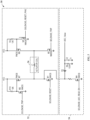
- FIG. 5 illustrates an example circuit 50 for controlling the operation of the electromagnetic actuator 34.
- the armature position detection circuit 30 may be implemented via the circuit 50.
- the circuit 50 includes an H-bridge circuit 52 that may control a polarity of a voltage or a direction of current flow to a coil of the electromagnetic actuator 34.
- the circuit 50 includes a measurement circuit 54, which may be enabled to detect a position of the armature 20.
- the H-bridge circuit 52 may be connected to an actuator coil 56, which may be part of the electromagnetic actuator 34.
- one side of the H-bridge circuit 52 may be used to trip or induce a magnetic field in the core of the electromagnetic actuator 34, and the other side of the H-bridge circuit 52 may be used to reset or remove the magnetic field in the core of the electromagnetic actuator 34.
- FIG. 6 illustrates an operation in which the H-bridge circuit 52 is used to trip the electromagnetic actuator 34.
- a control system or any suitable computing device may supply a solenoid trip signal (e.g., high signal) to a gate of an NMOS switch 58 to cause the NMOS switch 58 to close, thereby connecting a low signal (e.g., ground) to a gate of a PMOS switch 60.
- the PMOS switch 60 may close and provide a voltage to the actuator coil 56.
- the control system may also provide a solenoid trip signal (e.g., high signal) to an NMOS switch 62, thereby providing a current path from a voltage source Vcc to ground via the actuator coil 56.
- the current supplied to the actuator coil 56 may magnetize the core of the electromagnetic actuator 34, thereby causing the armature 20 to change states.
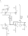
- the opposite side of the H-bridge circuit 52 may be driven, as illustrated in FIG. 7 .
- the control system may remove the solenoid trip signals (e.g., low signal) from gates of NMOS switch 58 and NMOS switch 62.
- the control system may provide solenoid reset signals (e.g., high signals) to gates of NMOS switch 64 and NMOS switch 66.
- the NMOS switch 64 and the NMOS switch 66 may close, thereby connecting a low signal (e.g., ground) to a gate of the PMOS switch 68.
- the current supplied to the actuator coil 56 may be reversed, as compared to the operation of the H-bridge circuit 52 depicted in FIG. 6 .
- the reversal of the current flow in the actuator coil 56 may cause the armature 20 to move to an opposite position, as compared to the position achieved with the circuit operation depicted in FIG. 6 .
- the measurement circuit 54 is disabled by connecting a low signal to a gate of NMOS switch 70. That is, the coil current in the modes of operations depicted in FIGS. 6 and 7 flow to a ground connection provided via NMOS switch 64 or NMOS switch 62.
- the control system may provide a read enable signal (e.g., high signal) to a gate of the NMOS switch 70, as depicted in FIG. 8 .
- the control system may provide a ping signal to the NMOS switch 66.
- the ping signal may be a pulse-width modulated signal that cycles between a high voltage value and a low voltage value over a period of time.
- the pulse-width modulated signal may be a voltage signal provided at 20 kHz and a 10% duty cycle.
- the control system may remove the solenoid trip signals and the solenoid reset signal from the NMOS switch 58, the NMOS switch 62, and the NMOS switch 64.
- the control system may cause the NMOS switch 70 to close thereby providing a current path to ground for the coil current conducting within the actuator coil 56.
- the ping signal consists of a pulse-width modulated signal
- the coil current through the actuator coil 56 is pulsed through a resistive load (e.g., resistor72 ) in the measurement circuit 54.
- a diode 76 may be used to rectify or convert the voltage into a digital signal that may be measured at output node 78. The voltage measured at the output node 78 is dependent on the inductance of the actuator coil 56.
- the position of the armature 20 is also dependent on the inductance of the actuator coil 56.
- the control system or any suitable computing device may detect the position (e.g., open or closed) of the armature 20.
- the diode 76 may be any suitable diode such as a Schottky diode, a Zener diode, or the like.
- FIG. 9 illustrates a timing diagram 90 that depicts the current detected at the node 74 during a trip operation, a reset operation, and a measurement detection operation of the example circuit 50.
- the solenoid reset signal may be provided to the NMOS switch 66 and the NMOS switch 64.
- the coil current of the actuator coil 56 may be a positive value (e.g., ⁇ 3.7A).
- the solenoid trip signal may be provided to the NMOS switch 58 and the NMOS switch 62 (solenoid reset signal removed from the NMOS switch 66 and the NMOS switch 64).
- the coil current of the actuator coil 56 may be a negative value (e.g., ⁇ -1.2A).
- the measurement circuit 54 may be activated as described above with reference to FIG. 8 .
- the detected coil current during position sensing has a relatively lower magnitude, as compared to the current magnitudes during the reset operation and the trip operation. In this way, the coil current is low enough to avoid affecting the trip or reset operations of the electromagnetic actuator.
- FIG. 10 illustrates a scaled view of the measured current at time t4.
- a first current trace 92 achieves a higher peak value, as compared to a second current trace 94.
- the first current trace 92 may correspond to a situation in which the armature 20 is in an open position and the core of the electromagnetic actuator 34 is not magnetized. That is, since the core of the electromagnetic actuator 34 is not magnetized, the inductance of the actuator coil 56 is higher than when the core of the electromagnetic actuator 34 is magnetized. This lower inductance causes the peak current to be greater than the peak current of the second current trace 94, which corresponds to when the armature 20 is in a closed position. That is, when the armature 20 is in the closed position, the inductance of the actuator coil 56 is lower than when the core of the electromagnetic actuator 34 is not magnetized.
- the diode 76 may rectify the coil current received at the node 74 to produce digital values, as shown in FIG. 11 .
- the first current trace 92 which corresponds to armature 20 being in an open position may correspond to a voltage signal 96.
- the second current trace 94 which corresponds to armature 20 being in a closed position may correspond to a voltage signal 98.
- the one-volt difference between the two voltage signals may be used to provide a digital indication of the position of the armature 20. Namely, the high voltage level may correspond to the armature 20 being in an open position and the low voltage level may correspond to the armature 20 being in a closed position.
- NMOS switches and PMOS switches any suitable switching technology (e.g., MOSFET, IGBT, BJT) may be employed to perform the operations of the circuit 50.
- MOSFET MOSFET
- IGBT IGBT
- BJT Bipolar MOSFET
- the NMOS switches can be changed to PMOS switches, and vice-versa, so long as the gate signals change accordingly.
- FIGS. 5-8 are provided as example switches, and the present disclosure should not be limited to the embodiments described in those figures.
- the control system may remotely access or the electromagnetic actuator 34 to determine the position of the armature 20.
- the remote detection of the position of the armature 20 may enable users to know the state of the electromagnetic actuator 34 regardless of whether a user has manually changed the state of the actuator. That is, the control system may leverage the inductance of the actuator coil 56 to remotely determine the position of the armature 20.
- the control system may then update a visualization to be presented via a display, send a notification to another computing device, or perform any other suitable operation to provide an indication regarding the position of the armature 20.
- the control system may determine whether the detected state of the armature 20 matches an expected state of the armature 20.
- control system may send solenoid trip or solenoid reset signals to respective gates of switches to cause the H-bridge circuit 52 to change state of the electromagnetic actuator 34 to match the expected state. In this way, the control system may remotely control the operation of the electromagnetic actuator 34, while also remotely detecting the position of the armature 20 without using additional hardware.
- the gate signals may be provided via a control system or any suitable computing device.
- the control system may include any suitable computing system, controller, or the like.
- the control system may include a communication component, a processor, a memory, a storage, input/output (I/O) ports, a display, and the like.
- the communication component may be a wireless or wired communication component that may facilitate communication between different components within the industrial automation system, to the electromagnetic actuator 34, or the like.
- the processor may be any type of computer processor or microprocessor capable of executing computer-executable code.
- the processor may also include multiple processors that may perform the operations described below.
- the memory and the storage may be any suitable articles of manufacture that can serve as media to store processor-executable code, data, or the like. These articles of manufacture may represent computer-readable media (e.g., any suitable form of memory or storage) that may store the processor-executable code used by the processor to perform the presently disclosed techniques.
- the memory and the storage may represent non-transitory computer-readable media (e.g., any suitable form of memory or storage) that may store the processor-executable code used by the processor to perform various techniques described herein. It should be noted that non-transitory merely indicates that the media is tangible and not a signal.
- the I/O ports may be interfaces that may couple to other peripheral components such as input devices (e.g., keyboard, mouse), sensors, input/output (I/O) modules, and the like.
- the display may operate to depict visualizations associated with software or executable code being processed by the processor.
- the display may be a touch display capable of receiving inputs from a user.
- the display may be any suitable type of display, such as a liquid crystal display (LCD), plasma display, or an organic light emitting diode (OLED) display, for example.
- the display may be provided in conjunction with a touch-sensitive mechanism (e.g., a touch screen) that may function as part of a control interface.
- a touch-sensitive mechanism e.g., a touch screen
- inventions described herein include providing the ability to remotely detect a position of an armature in an electromagnetic actuator without employing position sensing circuitry, such as optocouplers and the like. Indeed, the position of the armature may be detected remotely by providing a pulse-width modulated signal to the actuator coil and measuring a digital voltage output that changes based on the inductance of the actuator coil. In this way, present embodiments described herein may provide systems and methods for detecting the position of the armature without including additional sensing circuitry.
Landscapes
- Physics & Mathematics (AREA)
- Electromagnetism (AREA)
- Engineering & Computer Science (AREA)
- Power Engineering (AREA)
- Relay Circuits (AREA)
Claims (15)
- System zum Erfassen einer Position eines Ankers (20), umfassend:einen Anker, der einen ersten Kontakt umfasst und so konfiguriert ist, dass er sich zwischen einer ersten Position, die den ersten Kontakt des Ankers elektrisch mit einem zweiten Kontakt koppelt, und einer zweiten Position, die den ersten Kontakt des Ankers elektrisch mit einem dritten Kontakt koppelt, bewegt,eine Spule (56), die so konfiguriert ist, dass sie einen Strom empfängt, wobei der in der Spule fließende Strom so konfiguriert ist, dass er einen Kern magnetisiert, wodurch der Anker von der ersten Position in die zweite Position bewegt wird, eine H-Brückenschaltung (52), die so konfiguriert ist, dass sie die Spule mit Strom versorgt,eine Messschaltung (54), die so konfiguriert ist, dass sie eine Messung des Stroms erfasst, wobei die Messschaltung eine mit der Spule in Reihe geschaltete Widerstandslast (72) und einen Messschalter (70) umfasst, der so konfiguriert ist, dass er einen die Widerstandslast und die Spule umfassenden Strompfad zur Erde schließt, undein Steuersystem, das so konfiguriert ist, dass es die Position des Ankers basierend auf einer Induktivität der Spule erfasst, wobei das Erfassen der Position des Ankers umfasst:Senden einer Vielzahl von Gate-Signalen an eine Vielzahl von Schaltern der H-Brückenschaltung, die so konfiguriert sind, dass sie ein Öffnen der Vielzahl von Schaltern bewirken, wodurch der Betrieb der H-Brückenschaltung deaktiviert wird,Senden eines ersten Signals an den Messschalter, wobei das erste Signal so konfiguriert ist, dass es bewirkt, dass der Messschalter den Strompfad zur Erde schließt,Senden eines pulsbreitenmodulierten Signals an einen ersten Schalter, der Teil der H-Brückenschaltung ist, undMessen eines Stroms, der über den Messschalter geleitet wird, während das pulsbreitenmodulierte Signal an den ersten Schalter angelegt wird, wobei der Strom der Position des Ankers entspricht.
- System nach Anspruch 1, wobei die Messschaltung eine Diode umfasst, die so konfiguriert ist, dass sie die Messung des Stroms in einen Spannungswert umwandelt.
- System nach Anspruch 2, wobei das Steuersystem so konfiguriert ist, dass es die Position des Ankers auf der Grundlage des Spannungswerts bestimmt.
- System nach Anspruch 1, wobei der Messschalter so konfiguriert ist, dass er ein Gate-Signal empfängt, welches bewirkt, dass die Messschaltung die Messung des Stroms erfasst.
- System nach Anspruch 1, wobei das Steuersystem so konfiguriert ist, dass es ein oder mehrere Signale an die H-Brückenschaltung sendet, wobei das eine oder die mehreren Signale so konfiguriert ist/sind, dass es bewirkt, dass sich der Anker in die erste Position oder die zweite Position bewegt.
- Verfahren zum Erfassen einer Position eines Ankers (20) auf der Grundlage einer Induktivität einer Spule (56), wobei der Anker einen ersten Kontakt umfasst und so konfiguriert ist, dass er sich zwischen einer ersten Position, die den ersten Kontakt des Ankers elektrisch mit einem zweiten Kontakt koppelt, und einer zweiten Position, die den ersten Kontakt des Ankers mit einem dritten Kontakt elektrisch koppelt bewegt, wobei die Spule so konfiguriert ist, dass sie einen Strom empfängt, wobei der in der Spule fließende Strom so konfiguriert ist, dass er einen Kern magnetisiert, wodurch der Anker veranlasst wird, sich von der ersten Position in die zweite Position zu bewegen, wobei das Verfahren umfasst:Senden einer Vielzahl von Gate-Signalen über eine Schaltung an eine Vielzahl von Schaltern, die so konfiguriert sind, dass sie ein Öffnen der Vielzahl von Schaltern bewirken, wobei die Vielzahl von Schaltern Teil einer H-Brückenschaltung (52) ist, wodurch der Betrieb der H-Brückenschaltung deaktiviert wird, wobei die H-Brückenschaltung so konfiguriert ist, dass sie die Spule mit Strom versorgt, Senden eines ersten Signals über die Schaltung an einen ersten Schalter einer Messschaltung (54), wobei die Messschaltung so konfiguriert ist, dass sie eine Messung des Stroms erfasst, und eine mit der Spule in Reihe geschaltete Widerstandslast (72) umfasst, wobei das erste Signal so konfiguriert ist, dass es bewirkt, dass der erste Schalter einen Strompfad, der die Widerstandslast und die Spule umfasst, zur Erde schließt,Senden eines pulsbreitenmodulierten Signals über die Schaltung an einen zweiten Schalter, der Teil der H-Brückenschaltung ist, undMessen eines Stroms, der über den ersten Schalter fließt, während das pulsbreitenmodulierte Signal an den zweiten Schalter angelegt wird, wobei der Strom der Position des Ankers entspricht, über die Schaltung.
- Verfahren nach Anspruch 6, wobei das Senden der Vielzahl von Gate-Signalen an die Vielzahl von Schaltern umfasst:Senden eines zweiten Signals über eine Schaltung an einen zweiten Schalter und einen dritten Schalter, wobei der zweite Schalter und der dritte Schalter auf gegenüberliegenden Seiten der H-Brückenschaltung positioniert sind und wobei das zweite Signal so konfiguriert ist, dass es bewirkt, dass der zweite Schalter und der dritte Schalter öffnen, undSenden eines dritten Signals über eine Schaltung an einen vierten Schalter, wobei der vierte Schalter und der zweite Schalter auf gegenüberliegenden Seiten der H-Brückenschaltung positioniert sind, wobei das zweite Signal so konfiguriert ist, dass es das Öffnen des dritten Schalters bewirkt.
- Verfahren nach Anspruch 6 oder 7, wobei jeder der Vielzahl von Schaltern einen PMOS-Schalter umfasst.
- Verfahren nach Anspruch 6 oder 7, wobei jeder der Vielzahl von Schaltern einen NMOS-Schalter umfasst.
- Schaltung zum Erfassen einer Position eines Ankers (20), umfassend:eine Spule (56), die so konfiguriert ist, dass sie einen Strom empfängt, wobei der in der Spule fließende Strom so konfiguriert ist, dass er einen Kern magnetisiert, wodurch ein Anker veranlasst wird, sich von einer ersten Position zu einer zweiten Position zu bewegen,wobei der Anker einen ersten Kontakt umfasst und so konfiguriert ist, dass er sich zwischen der ersten Position, die den ersten Kontakt des Ankers mit einem zweiten Kontakt elektrisch koppelt, und der zweiten Position, die den ersten Kontakt des Ankers mit einem dritten Kontakt elektrisch koppelt, bewegt,eine H-Brückenschaltung (52), die so konfiguriert ist, dass sie der Spule den Strom zuführt,eine Messschaltung (54), die so konfiguriert ist, dass sie eine Messung des Stroms erfasst, wobei die Messschaltung eine mit der Spule in Reihe geschaltete Widerstandslast (72) und einen Messschalter (70) umfasst, welcher so konfiguriert ist, dass er einen Strompfad, der die Widerstandslast und die Spule umfasst, zur Erde schließt,wobei die Position des Ankers auf der Grundlage einer Induktivität der Spule erfasst wird undwobei das Erfassen der Position des Ankers umfasst:Empfangen einer Vielzahl von Gate-Signalen an einer Vielzahl von Schaltern der H-Brückenschaltung, welche so konfiguriert sind, dass sie bewirken, dass die Vielzahl von Schaltern öffnet, wodurch der Betrieb der H-Brückenschaltung deaktiviert wird,Empfangen eines ersten Signals an dem Messschalter, welches so konfiguriert ist, dass es bewirkt, dass der Messschalter den Strompfad zur Erde schließt,Empfangen eines pulsbreitenmodulierten Signals an einem ersten Schalter, der Teil der H-Brückenschaltung ist, undMessen eines Stroms, der über den Messschalter fließt, während das pulsbreitenmodulierte Signal an den ersten Schalter angelegt wird, wobei der Strom der Position des Ankers entspricht.
- Schaltung nach Anspruch 10, die ferner eine Diode umfasst, welche mit der Spule und der Widerstandslast gekoppelt ist, wobei die Diode so konfiguriert ist, dass sie eine Gleichspannung basierend auf dem Strom bereitstellt,
wobei die Gleichspannung für eine Induktivität der Spule repräsentativ ist. - Schaltung nach Anspruch 10 oder 11, wobei die Vielzahl von Schaltern einen oder mehrere PMOS-Schalter und eine Vielzahl von NMOS-Schaltern umfasst.
- Schaltung nach einem der Ansprüche 10 bis 12, wobei der erste Schalter so konfiguriert ist, dass er das pulsbreitenmodulierte Signal an einem Gate empfängt, und/oder
wobei das pulsbreitenmodulierte Signal 20 kHz und ein Tastverhältnis von 10 % umfasst. - Schaltung nach einem der Ansprüche 10 bis 13, umfassend eine Steuerung, die so konfiguriert ist, dass sie eine Vielzahl von Signalen ausgibt, um einen oder mehrere Vorgänge der Vielzahl von Schaltern zu steuern.
- Schaltung nach einem der Ansprüche 10 bis 14, wobei die Vielzahl von Schaltern so konfiguriert ist, dass sie einen Stromfluss durch die Spule steuert, oder
wobei jeder der Vielzahl von Schaltern mit Masse verbunden ist.
Applications Claiming Priority (1)
| Application Number | Priority Date | Filing Date | Title |
|---|---|---|---|
| US16/929,946 US11521815B2 (en) | 2020-07-15 | 2020-07-15 | Detecting a position of an armature in an electromagnetic actuator |
Publications (2)
| Publication Number | Publication Date |
|---|---|
| EP3944267A1 EP3944267A1 (de) | 2022-01-26 |
| EP3944267B1 true EP3944267B1 (de) | 2024-11-06 |
Family
ID=76532070
Family Applications (1)
| Application Number | Title | Priority Date | Filing Date |
|---|---|---|---|
| EP21180356.4A Active EP3944267B1 (de) | 2020-07-15 | 2021-06-18 | Detektion der position eines ankers in einem elektromagnetischen aktuator |
Country Status (2)
| Country | Link |
|---|---|
| US (1) | US11521815B2 (de) |
| EP (1) | EP3944267B1 (de) |
Families Citing this family (1)
| Publication number | Priority date | Publication date | Assignee | Title |
|---|---|---|---|---|
| WO2024215312A1 (en) * | 2023-04-12 | 2024-10-17 | Saia-Burgess Llc | Method and system for closed-loop feed forward control of actuation of a solenoid |
Family Cites Families (24)
| Publication number | Priority date | Publication date | Assignee | Title |
|---|---|---|---|---|
| US4809742A (en) | 1988-04-18 | 1989-03-07 | Pneumo Abex Corporation | Control valve assembly including valve position sensor |
| DE4201652C2 (de) * | 1992-01-22 | 1997-11-06 | Rexroth Mannesmann Gmbh | Proportionalventil mit Ansteuerschaltung und Netzspannungsbetrieb |
| JP3508407B2 (ja) | 1996-08-01 | 2004-03-22 | 株式会社日立製作所 | 内燃機関用燃料噴射弁の駆動装置 |
| US5942892A (en) * | 1997-10-06 | 1999-08-24 | Husco International, Inc. | Method and apparatus for sensing armature position in direct current solenoid actuators |
| US6249418B1 (en) | 1999-01-27 | 2001-06-19 | Gary Bergstrom | System for control of an electromagnetic actuator |
| HK1049265A2 (en) * | 2002-02-27 | 2003-04-11 | Clipsal Asia Holdings Limited | A two-wire power switch with line-powered switch controlling means |
| US6876510B2 (en) * | 2002-03-18 | 2005-04-05 | Seagate Technology Llc | Detecting head landings on a data zone of a data storage disc |
| DE10235188B3 (de) * | 2002-07-26 | 2004-04-01 | Hydac Electronic Gmbh | Verfahren zum Ermitteln der Position eines Stellelements eines elektrisch antreibbaren Aktuators, zugehörige Schaltungsanordnung und Vorrichtung |
| US6869060B2 (en) * | 2003-04-04 | 2005-03-22 | Husco International, Inc. | Hydraulic poppet valve with force feedback |
| GB201110699D0 (en) * | 2011-06-24 | 2011-08-10 | Camcon Oil Ltd | Electromagnetic actuators and monitoring thereof |
| CN103594288B (zh) * | 2012-08-17 | 2015-07-29 | 光宝电子(广州)有限公司 | 继电器驱动装置及其驱动方法 |
| US20140354269A1 (en) * | 2013-05-28 | 2014-12-04 | Parker-Hannifin Corporation | Method and apparatus for determining the condition of a control element |
| WO2016153972A1 (en) | 2015-03-20 | 2016-09-29 | Dana Automotive Systems Group, Llc | Induction based position sensing in an electromagnetic actuator |
| CN105137761B (zh) * | 2015-09-28 | 2018-03-13 | 武汉大学 | 三线圈姿态可调的电磁力反馈装置及其姿态计算与电流智能控制方法 |
| DE102016220190A1 (de) | 2016-10-17 | 2018-04-19 | Robert Bosch Gmbh | Verfahren zum gepulsten Ansteuern einer Last mittels einer H-Brückenschaltung |
| US10084402B2 (en) * | 2016-10-17 | 2018-09-25 | Texas Instruments Incorporated | Microstepper motor control circuit PWM output coupled to H-bridge gates |
| EP3312549B1 (de) | 2016-10-21 | 2020-05-06 | General Electric Technology GmbH | Elektrische baugruppe |
| US10366854B2 (en) * | 2016-11-30 | 2019-07-30 | Te Connectivity Corporation | Contactor with coil polarity reversing control circuit |
| EP3874132A1 (de) * | 2018-10-31 | 2021-09-08 | Eaton Intelligent Power Limited | Diagnoseverfahren an bord für elektromagnetische verriegelungsanordnung |
| CN210837600U (zh) * | 2019-08-30 | 2020-06-23 | 南宁职业技术学院 | 磁保持继电器驱动装置 |
| US11462345B2 (en) * | 2019-09-30 | 2022-10-04 | Rockwell Automation Technologies, Inc. | Systems and methods for controlling contactor bounce |
| US11415629B2 (en) * | 2019-09-30 | 2022-08-16 | Rockwell Automation Technologies, Inc. | Relay coil drive circuit |
| US11394321B2 (en) * | 2019-09-30 | 2022-07-19 | Rockwell Automation Technologies, Inc. | Systems and methods for de-energized point-on-wave relay operations |
| US11676786B2 (en) * | 2020-04-09 | 2023-06-13 | Rockwell Automation Technologies, Inc. | Systems and methods for controlling contactor open time |
-
2020
- 2020-07-15 US US16/929,946 patent/US11521815B2/en active Active
-
2021
- 2021-06-18 EP EP21180356.4A patent/EP3944267B1/de active Active
Also Published As
| Publication number | Publication date |
|---|---|
| US20220020549A1 (en) | 2022-01-20 |
| EP3944267A1 (de) | 2022-01-26 |
| US11521815B2 (en) | 2022-12-06 |
Similar Documents
| Publication | Publication Date | Title |
|---|---|---|
| CN101813750B (zh) | 接触器磨损老化检测装置及方法 | |
| TW432129B (en) | Device for manufacturing single crystals | |
| US10324431B2 (en) | Method for monitoring an electromechanical component of an automation system | |
| US11651918B2 (en) | Sensing properties of switching devices using back EMF measurements | |
| US8159807B2 (en) | Method and device for operating a switching device | |
| CN208848084U (zh) | 用于工业过程的现场设备、工业过程控制系统 | |
| US12347636B2 (en) | Systems and methods for detecting welded contacts in a switch system | |
| EP3944267B1 (de) | Detektion der position eines ankers in einem elektromagnetischen aktuator | |
| EP4156221B1 (de) | Systeme und verfahren zur erkennung geschweisster kontakte in einem elektromagnetischen schaltsystem | |
| US11380506B2 (en) | Method for monitoring an electromechanical component of an automated system | |
| KR101532885B1 (ko) | 릴레이 접점 융착 경고 시스템 및 방법 | |
| CN109478476B (zh) | 用于中压断路器的致动器 | |
| EP3893259B1 (de) | Systeme und verfahren zur steuerung der offenzeit eines schützes | |
| JP2013109997A (ja) | 電磁操作機構の駆動回路 | |
| US10692675B2 (en) | Contactor having electronic coil control | |
| CN103354943B (zh) | 可配置电磁线圈的驱动方法及装置 | |
| JP2010257660A (ja) | 真空遮断器の操作回路 | |
| JP2025114113A (ja) | 磁極位置検出システム、磁極位置検出方法、および磁極位置検出プログラム | |
| CN223986458U (zh) | 开关电磁铁 | |
| CN201196937Y (zh) | 一种基于永磁机构的低压接触器 | |
| CN213092958U (zh) | 一种节能型自保持位置电磁铁 | |
| EP3525224A1 (de) | Elektrische baugruppe | |
| CN204809127U (zh) | 电磁的接触器 | |
| RU112493U1 (ru) | Электромагнитный привод | |
| CN120261240A (zh) | 基于多元在线自诊断的剩磁式操动机构及其自诊断方法 |
Legal Events
| Date | Code | Title | Description |
|---|---|---|---|
| PUAI | Public reference made under article 153(3) epc to a published international application that has entered the european phase |
Free format text: ORIGINAL CODE: 0009012 |
|
| STAA | Information on the status of an ep patent application or granted ep patent |
Free format text: STATUS: THE APPLICATION HAS BEEN PUBLISHED |
|
| AK | Designated contracting states |
Kind code of ref document: A1 Designated state(s): AL AT BE BG CH CY CZ DE DK EE ES FI FR GB GR HR HU IE IS IT LI LT LU LV MC MK MT NL NO PL PT RO RS SE SI SK SM TR |
|
| STAA | Information on the status of an ep patent application or granted ep patent |
Free format text: STATUS: REQUEST FOR EXAMINATION WAS MADE |
|
| 17P | Request for examination filed |
Effective date: 20220726 |
|
| RBV | Designated contracting states (corrected) |
Designated state(s): AL AT BE BG CH CY CZ DE DK EE ES FI FR GB GR HR HU IE IS IT LI LT LU LV MC MK MT NL NO PL PT RO RS SE SI SK SM TR |
|
| GRAP | Despatch of communication of intention to grant a patent |
Free format text: ORIGINAL CODE: EPIDOSNIGR1 |
|
| STAA | Information on the status of an ep patent application or granted ep patent |
Free format text: STATUS: GRANT OF PATENT IS INTENDED |
|
| INTG | Intention to grant announced |
Effective date: 20240607 |
|
| GRAS | Grant fee paid |
Free format text: ORIGINAL CODE: EPIDOSNIGR3 |
|
| GRAA | (expected) grant |
Free format text: ORIGINAL CODE: 0009210 |
|
| STAA | Information on the status of an ep patent application or granted ep patent |
Free format text: STATUS: THE PATENT HAS BEEN GRANTED |
|
| AK | Designated contracting states |
Kind code of ref document: B1 Designated state(s): AL AT BE BG CH CY CZ DE DK EE ES FI FR GB GR HR HU IE IS IT LI LT LU LV MC MK MT NL NO PL PT RO RS SE SI SK SM TR |
|
| REG | Reference to a national code |
Ref country code: GB Ref legal event code: FG4D |
|
| REG | Reference to a national code |
Ref country code: CH Ref legal event code: EP |
|
| REG | Reference to a national code |
Ref country code: DE Ref legal event code: R096 Ref document number: 602021021270 Country of ref document: DE |
|
| REG | Reference to a national code |
Ref country code: IE Ref legal event code: FG4D |
|
| REG | Reference to a national code |
Ref country code: LT Ref legal event code: MG9D |
|
| REG | Reference to a national code |
Ref country code: NL Ref legal event code: MP Effective date: 20241106 |
|
| PG25 | Lapsed in a contracting state [announced via postgrant information from national office to epo] |
Ref country code: PT Free format text: LAPSE BECAUSE OF FAILURE TO SUBMIT A TRANSLATION OF THE DESCRIPTION OR TO PAY THE FEE WITHIN THE PRESCRIBED TIME-LIMIT Effective date: 20250306 Ref country code: HR Free format text: LAPSE BECAUSE OF FAILURE TO SUBMIT A TRANSLATION OF THE DESCRIPTION OR TO PAY THE FEE WITHIN THE PRESCRIBED TIME-LIMIT Effective date: 20241106 Ref country code: IS Free format text: LAPSE BECAUSE OF FAILURE TO SUBMIT A TRANSLATION OF THE DESCRIPTION OR TO PAY THE FEE WITHIN THE PRESCRIBED TIME-LIMIT Effective date: 20250306 |
|
| PG25 | Lapsed in a contracting state [announced via postgrant information from national office to epo] |
Ref country code: FI Free format text: LAPSE BECAUSE OF FAILURE TO SUBMIT A TRANSLATION OF THE DESCRIPTION OR TO PAY THE FEE WITHIN THE PRESCRIBED TIME-LIMIT Effective date: 20241106 Ref country code: NL Free format text: LAPSE BECAUSE OF FAILURE TO SUBMIT A TRANSLATION OF THE DESCRIPTION OR TO PAY THE FEE WITHIN THE PRESCRIBED TIME-LIMIT Effective date: 20241106 |
|
| REG | Reference to a national code |
Ref country code: AT Ref legal event code: MK05 Ref document number: 1740335 Country of ref document: AT Kind code of ref document: T Effective date: 20241106 |
|
| PG25 | Lapsed in a contracting state [announced via postgrant information from national office to epo] |
Ref country code: BG Free format text: LAPSE BECAUSE OF FAILURE TO SUBMIT A TRANSLATION OF THE DESCRIPTION OR TO PAY THE FEE WITHIN THE PRESCRIBED TIME-LIMIT Effective date: 20241106 |
|
| PG25 | Lapsed in a contracting state [announced via postgrant information from national office to epo] |
Ref country code: ES Free format text: LAPSE BECAUSE OF FAILURE TO SUBMIT A TRANSLATION OF THE DESCRIPTION OR TO PAY THE FEE WITHIN THE PRESCRIBED TIME-LIMIT Effective date: 20241106 |
|
| PG25 | Lapsed in a contracting state [announced via postgrant information from national office to epo] |
Ref country code: NO Free format text: LAPSE BECAUSE OF FAILURE TO SUBMIT A TRANSLATION OF THE DESCRIPTION OR TO PAY THE FEE WITHIN THE PRESCRIBED TIME-LIMIT Effective date: 20250206 |
|
| PG25 | Lapsed in a contracting state [announced via postgrant information from national office to epo] |
Ref country code: AT Free format text: LAPSE BECAUSE OF FAILURE TO SUBMIT A TRANSLATION OF THE DESCRIPTION OR TO PAY THE FEE WITHIN THE PRESCRIBED TIME-LIMIT Effective date: 20241106 Ref country code: LV Free format text: LAPSE BECAUSE OF FAILURE TO SUBMIT A TRANSLATION OF THE DESCRIPTION OR TO PAY THE FEE WITHIN THE PRESCRIBED TIME-LIMIT Effective date: 20241106 Ref country code: GR Free format text: LAPSE BECAUSE OF FAILURE TO SUBMIT A TRANSLATION OF THE DESCRIPTION OR TO PAY THE FEE WITHIN THE PRESCRIBED TIME-LIMIT Effective date: 20250207 |
|
| PG25 | Lapsed in a contracting state [announced via postgrant information from national office to epo] |
Ref country code: PL Free format text: LAPSE BECAUSE OF FAILURE TO SUBMIT A TRANSLATION OF THE DESCRIPTION OR TO PAY THE FEE WITHIN THE PRESCRIBED TIME-LIMIT Effective date: 20241106 |
|
| PG25 | Lapsed in a contracting state [announced via postgrant information from national office to epo] |
Ref country code: RS Free format text: LAPSE BECAUSE OF FAILURE TO SUBMIT A TRANSLATION OF THE DESCRIPTION OR TO PAY THE FEE WITHIN THE PRESCRIBED TIME-LIMIT Effective date: 20250206 |
|
| PG25 | Lapsed in a contracting state [announced via postgrant information from national office to epo] |
Ref country code: SM Free format text: LAPSE BECAUSE OF FAILURE TO SUBMIT A TRANSLATION OF THE DESCRIPTION OR TO PAY THE FEE WITHIN THE PRESCRIBED TIME-LIMIT Effective date: 20241106 |
|
| PGFP | Annual fee paid to national office [announced via postgrant information from national office to epo] |
Ref country code: DE Payment date: 20250520 Year of fee payment: 5 |
|
| PG25 | Lapsed in a contracting state [announced via postgrant information from national office to epo] |
Ref country code: DK Free format text: LAPSE BECAUSE OF FAILURE TO SUBMIT A TRANSLATION OF THE DESCRIPTION OR TO PAY THE FEE WITHIN THE PRESCRIBED TIME-LIMIT Effective date: 20241106 |
|
| PGFP | Annual fee paid to national office [announced via postgrant information from national office to epo] |
Ref country code: GB Payment date: 20250520 Year of fee payment: 5 |
|
| PG25 | Lapsed in a contracting state [announced via postgrant information from national office to epo] |
Ref country code: EE Free format text: LAPSE BECAUSE OF FAILURE TO SUBMIT A TRANSLATION OF THE DESCRIPTION OR TO PAY THE FEE WITHIN THE PRESCRIBED TIME-LIMIT Effective date: 20241106 |
|
| PGFP | Annual fee paid to national office [announced via postgrant information from national office to epo] |
Ref country code: FR Payment date: 20250520 Year of fee payment: 5 |
|
| PG25 | Lapsed in a contracting state [announced via postgrant information from national office to epo] |
Ref country code: RO Free format text: LAPSE BECAUSE OF FAILURE TO SUBMIT A TRANSLATION OF THE DESCRIPTION OR TO PAY THE FEE WITHIN THE PRESCRIBED TIME-LIMIT Effective date: 20241106 |
|
| PG25 | Lapsed in a contracting state [announced via postgrant information from national office to epo] |
Ref country code: SK Free format text: LAPSE BECAUSE OF FAILURE TO SUBMIT A TRANSLATION OF THE DESCRIPTION OR TO PAY THE FEE WITHIN THE PRESCRIBED TIME-LIMIT Effective date: 20241106 |
|
| PG25 | Lapsed in a contracting state [announced via postgrant information from national office to epo] |
Ref country code: CZ Free format text: LAPSE BECAUSE OF FAILURE TO SUBMIT A TRANSLATION OF THE DESCRIPTION OR TO PAY THE FEE WITHIN THE PRESCRIBED TIME-LIMIT Effective date: 20241106 |
|
| PG25 | Lapsed in a contracting state [announced via postgrant information from national office to epo] |
Ref country code: IT Free format text: LAPSE BECAUSE OF FAILURE TO SUBMIT A TRANSLATION OF THE DESCRIPTION OR TO PAY THE FEE WITHIN THE PRESCRIBED TIME-LIMIT Effective date: 20241106 |
|
| REG | Reference to a national code |
Ref country code: DE Ref legal event code: R097 Ref document number: 602021021270 Country of ref document: DE |
|
| PG25 | Lapsed in a contracting state [announced via postgrant information from national office to epo] |
Ref country code: SE Free format text: LAPSE BECAUSE OF FAILURE TO SUBMIT A TRANSLATION OF THE DESCRIPTION OR TO PAY THE FEE WITHIN THE PRESCRIBED TIME-LIMIT Effective date: 20241106 |
|
| PLBE | No opposition filed within time limit |
Free format text: ORIGINAL CODE: 0009261 |
|
| STAA | Information on the status of an ep patent application or granted ep patent |
Free format text: STATUS: NO OPPOSITION FILED WITHIN TIME LIMIT |
|
| 26N | No opposition filed |
Effective date: 20250807 |
|
| REG | Reference to a national code |
Ref country code: CH Ref legal event code: H13 Free format text: ST27 STATUS EVENT CODE: U-0-0-H10-H13 (AS PROVIDED BY THE NATIONAL OFFICE) Effective date: 20260127 |
|
| PG25 | Lapsed in a contracting state [announced via postgrant information from national office to epo] |
Ref country code: MC Free format text: LAPSE BECAUSE OF FAILURE TO SUBMIT A TRANSLATION OF THE DESCRIPTION OR TO PAY THE FEE WITHIN THE PRESCRIBED TIME-LIMIT Effective date: 20241106 |
|
| PG25 | Lapsed in a contracting state [announced via postgrant information from national office to epo] |
Ref country code: LU Free format text: LAPSE BECAUSE OF NON-PAYMENT OF DUE FEES Effective date: 20250618 |
|
| REG | Reference to a national code |
Ref country code: BE Ref legal event code: MM Effective date: 20250630 |
|
| PG25 | Lapsed in a contracting state [announced via postgrant information from national office to epo] |
Ref country code: IE Free format text: LAPSE BECAUSE OF NON-PAYMENT OF DUE FEES Effective date: 20250618 |
|
| PG25 | Lapsed in a contracting state [announced via postgrant information from national office to epo] |
Ref country code: BE Free format text: LAPSE BECAUSE OF NON-PAYMENT OF DUE FEES Effective date: 20250630 |
|
| PG25 | Lapsed in a contracting state [announced via postgrant information from national office to epo] |
Ref country code: CH Free format text: LAPSE BECAUSE OF NON-PAYMENT OF DUE FEES Effective date: 20250630 |