EP4156221B1 - Systeme und verfahren zur erkennung geschweisster kontakte in einem elektromagnetischen schaltsystem - Google Patents
Systeme und verfahren zur erkennung geschweisster kontakte in einem elektromagnetischen schaltsystem Download PDFInfo
- Publication number
- EP4156221B1 EP4156221B1 EP22198007.1A EP22198007A EP4156221B1 EP 4156221 B1 EP4156221 B1 EP 4156221B1 EP 22198007 A EP22198007 A EP 22198007A EP 4156221 B1 EP4156221 B1 EP 4156221B1
- Authority
- EP
- European Patent Office
- Prior art keywords
- coil
- contacts
- relay device
- voltage
- relay
- Prior art date
- Legal status (The legal status is an assumption and is not a legal conclusion. Google has not performed a legal analysis and makes no representation as to the accuracy of the status listed.)
- Active
Links
Images



Classifications
-
- H—ELECTRICITY
- H01—ELECTRIC ELEMENTS
- H01H—ELECTRIC SWITCHES; RELAYS; SELECTORS; EMERGENCY PROTECTIVE DEVICES
- H01H47/00—Circuit arrangements not adapted to a particular application of the relay and designed to obtain desired operating characteristics or to provide energising current
- H01H47/002—Monitoring or fail-safe circuits
-
- H—ELECTRICITY
- H01—ELECTRIC ELEMENTS
- H01H—ELECTRIC SWITCHES; RELAYS; SELECTORS; EMERGENCY PROTECTIVE DEVICES
- H01H50/00—Details of electromagnetic relays
- H01H50/16—Magnetic circuit arrangements
- H01H50/18—Movable parts of magnetic circuits, e.g. armature
-
- H—ELECTRICITY
- H01—ELECTRIC ELEMENTS
- H01H—ELECTRIC SWITCHES; RELAYS; SELECTORS; EMERGENCY PROTECTIVE DEVICES
- H01H50/00—Details of electromagnetic relays
- H01H50/44—Magnetic coils or windings
-
- H—ELECTRICITY
- H01—ELECTRIC ELEMENTS
- H01H—ELECTRIC SWITCHES; RELAYS; SELECTORS; EMERGENCY PROTECTIVE DEVICES
- H01H47/00—Circuit arrangements not adapted to a particular application of the relay and designed to obtain desired operating characteristics or to provide energising current
- H01H47/002—Monitoring or fail-safe circuits
- H01H2047/003—Detecting welded contacts and applying weld break pulses to coil
-
- H—ELECTRICITY
- H01—ELECTRIC ELEMENTS
- H01H—ELECTRIC SWITCHES; RELAYS; SELECTORS; EMERGENCY PROTECTIVE DEVICES
- H01H9/00—Details of switching devices, not covered by groups H01H1/00 - H01H7/00
- H01H9/16—Indicators for switching condition, e.g. "on" or "off"
- H01H9/167—Circuits for remote indication
Definitions
- switching devices are generally used throughout industrial, commercial, material handling, process and manufacturing settings, to mention only a few.
- switching device is generally intended to describe any type of electromechanical switching device, such as mechanical switching devices (e.g., a contactor, a relay, air break devices, and controlled atmosphere devices) or solid-state devices (e.g., a silicon-controlled rectifier (SCR)). More specifically, switching devices generally open to disconnect electric power from a load and close to connect electric power to the load. For example, switching devices may connect and disconnect three-phase electric power to an electric motor. Over time, these switching devices may begin to wear and operate less effectively. As such, it may be desirable to monitor the wear and state of the switching devices over time to ensure proper operations.
- mechanical switching devices e.g., a contactor, a relay, air break devices, and controlled atmosphere devices
- solid-state devices e.g., a silicon-controlled rectifier (SCR)
- SCR silicon-controlled rectifier
- EP 2 892 071 A1 relates to a deposition detection circuit provided in a deposition detection device that includes a determination circuit that determines whether the movable contact is deposited based on a step input signal and a transient response signal when a drive signal is in an off state.
- the transient response signal is generated so as to correspond to voltage less than or equal to operating voltage of the electromagnetic relay switch according to an excitation coil and a fixed resistor.
- EP 3 113 203 A1 relates to an abnormal operation of a movable contact that is correctly detected.
- the abnormal operation of the movable contact to the fixed contact is detected based on at least one of a separation transient response signal of a coil current passed through the excitation coil during the supply of a separation pulse signal and an attraction transient response signal of the coil current during the supply of an attraction pulse signal.
- US 6,233,132 B1 discloses an electromechanical relay drive system which prolongs relay life by ensuring operation of the relay in a manner to make and break contact between the contact electrodes at a zero crossing point of the switched waveform.
- Relay aging and environmental variations are dynamically compensated upon each actuation of the electromechanical relay to ensure proper timing of the energization and de-energization of the relay to ensure switching at the zero crossing point.
- the drive system described compensates for variations in the actual contact operation during actuation for the positive and negative half cycle of the switched waveform.
- the system of the instant invention alternately energizes and deenergizes the electromechanical relay during the positive and negative half cycles of the switched waveform to prevent metal deposition from one contact electrode to the other. This system calculates the appropriate delays on a dynamic historical perspective by sensing slope changes of the coil voltage and current.
- a non-transitory, computer-readable medium according to the invention is described in claim 12.
- switching devices are used in various implementations-such as industrial, commercial, material handling, manufacturing, power conversion, or power distribution-to connect or disconnect electric power from a load.
- a number of switching devices may be used to control operations, monitor conditions, and perform other operations related to various equipment in an industrial automation system.
- the switching devices may be used to coordinate operations across a number of devices.
- the contacts of the switching device may weld or partially weld together due to an excessive quantity of start-up current applied when providing power to the electric motor or from bouncing of the contacts of the switching device as the contacts close, or both.
- Switching devices with contacts that are welded together or partially welded together may pose various electrical and mechanical issues. For example, such switching devices may prevent power from being disconnected from electric motors. As such, it may be desirable to detect welded or partially welded contacts of switching contacts before closing the switching devices to connect electric power to an electric motor.
- a switching device may include a relay device that has an armature that may couple a common contact of the relay device to a corresponding contact of an electric circuit.
- the armature may electrically couple the common contact of the relay device to the corresponding contact of the electric circuit depending on a state of the relay device.
- the switching device include a Form A contact structure, a Form B contact structure, a Form C contact structure, a single-pole, single-throw double-break contact structure, or the like.
- the armature is positioned such that the common contact and a first contact of the electric circuit are electrically coupled to each other (i.e., the switching device is open) when a relay coil of the relay device is not energized or does not receive voltage or current from a driving circuit.
- the relay coil of the relay device receives voltage or current from a driving circuit, the relay coil magnetizes and attracts the armature to the relay coil, thereby connecting the common contact to the second contact of the electric circuit (i.e., the switching device is closed). In this way, an open switching device may disconnect electric power from a load, and a closed switching device may connect electric power to the load.
- the electrical connections between the common contact and the first contact and the second contact of the electric circuit are made via one or more respective intermediate contacts.
- the intermediate contacts that are used to make and break the electrical connections between the common contact and the second contact may become susceptible to being welded together.
- the switching device may become fixed in a closed state, such that the common contact of the armature remains electrically coupled to the second contact to provide electric power to the load. Because the intermediary contacts are welded together, the switching device may be prevented from opening, thereby maintaining the connection of electric power to the load. This, in turn, may cause electrical and mechanical safety issues, such as the inability to disable electric power to the load.
- embodiments of the present disclosure are directed to determining whether a contact of a relay device (e.g., having a Form A contact structure, a Form B contact structure, a Form C contact structure, a SPST contact structure, or other suitable contact structure) is at least partially welded to a corresponding contact of an electric circuit before energizing the relay device to connect electric power to a load.
- a contact of a relay device e.g., having a Form A contact structure, a Form B contact structure, a Form C contact structure, a SPST contact structure, or other suitable contact structure
- a contact of a relay device e.g., having a Form A contact structure, a Form B contact structure, a Form C contact structure, a SPST contact structure, or other suitable contact structure
- the contact of the relay device and the corresponding contact of the electric circuit may stick together, such that an armature of the relay device may be prevented from retracting to a position to disconnect electric power from a load.
- the relay coil of the relay device may be supplied (e.g., pinged) with a non-intrusive voltage pulse or a non-intrusive current pulse to detect whether the contact of the relay device is at least partially welded to the corresponding contact of the electric circuit. That is, an at least partially welded contact of the relay device may be detected without powering the relay coil to connect electric power to the load and without relying on respective sensors on respective contacts of the relay device to detect such at least partially welded contacts. For instance, the inductance of the relay coil will be different if a contact of the relay device is at least partially welded to a contact of the electric circuit than the inductance of the relay coil without an at least partially welded contact.
- the relay coil may be driven with either a fixed current profile or a fixed voltage profile.
- a fixed current profile may be used to drive the relay coil and the resulting coil voltage may be measured over time
- a contact of the relay device is at least partially welded to a contact of the electric circuit
- a deviation in relay coil inductance may exhibit in the voltage measurements of the relay coil used to maintain the fixed current profile driving the relay coil. That is, the voltage response (e.g., values of one or more voltage measurements) exhibited by the relay coil over time may correspond to a relay device having an at least partially welded contact.
- a partially welded contact of the relay device or a welded contact of the relay device may be detected without powering on the relay coil to connect electric power to the load and without relying on respective sensors on the contacts of the relay device to detect such partially welded or welded contacts. Additional details with regard to detecting welded switching devices will be described below with reference to FIGS. 1-7 .
- FIG. 1 depicts a system 10 that includes a power source 12, a load 14, and switchgear 16, which includes one or more switching devices that may be controlled using the techniques described herein.
- the switchgear 16 may selectively connect or disconnect three-phase electric power output by the power source 12 to the load 14, which may be an electric motor or any other powered device. In this manner, electrical power flows from the power source 12 to the load 14.
- switching devices in the switchgear 16 may close to connect electric power to the load 14.
- the switching devices in the switchgear 16 may open to disconnect electric power from the load 14.
- the power source 12 may be an electrical grid.
- energy may flow from the power source 12 to the load 14.
- energy may flow from the load 14 to the power source 12 (e.g., a wind turbine or another generator). More specifically, in some embodiments, energy flow from the load 14 to the power source 12 may transiently occur, for example, when overhauling a motor.
- control and monitoring circuitry 18 may be controlled by control and monitoring circuitry 18. More specifically, the control and monitoring circuitry 18 may instruct the switchgear 16 to connect or disconnect electric power. Accordingly, the control and monitoring circuitry 18 may include one or more processors 19 and memory 20. More specifically, as will be described in more detail below, the memory 20 may be a tangible, non-transitory, computer-readable medium that stores instructions, which when executed by the one or more processors 19 perform various processes described. It should be noted that non-transitory merely indicates that the media is tangible and not a signal. Many different algorithms and control strategies may be stored in the memory and implemented by the processor 19, and these will typically depend upon the nature of the load, the anticipated mechanical and electrical behavior of the load, the particular implementation, behavior of the switching devices, and so forth.
- control and monitoring circuitry 18 may be remote from the switchgear 16.
- the control and monitoring circuitry 18 may be communicatively coupled to the switchgear 16 via a network 21.
- the network 21 may utilize various communication protocols such as DeviceNet, Profibus, Modbus, and Ethernet, to only mention a few.
- to transmit signals between the control and monitoring circuitry 18 may utilize the network 21 to send, make, or break instructions to the switchgear 16.
- the network 21 may also communicatively couple the control and monitoring circuitry 18 to other parts of the system 10, such as other control circuitry or a human-machine-interface (not separately depicted).
- the control and monitoring circuitry 18 may be included in the switchgear 16 or directly coupled to the switchgear, for example, via a serial cable.
- the electric power input to the switchgear 16 and output from the switchgear 16 may be monitored by sensors 22.
- the sensors 22 may monitor (e.g., measure) the characteristics (e.g., voltage or current) of the electric power.
- the sensors 22 may include voltage sensors and current sensors. These sensors may alternatively be modeled or calculated values determined based on other measurements (e.g., virtual sensors). Many other sensors and input devices may be used, depending upon the parameters available and the application.
- the characteristics of the electric power measured by the sensors 22 may be communicated to the control and monitoring circuitry 18 and used as the basis for algorithmic computation and generation of waveforms (e.g., voltage waveforms or current waveforms) that depict the electric power.
- the waveforms generated based on input from the sensors 22 monitoring the electric power input into the switchgear 16 may be used to define the control of the switching devices, for example, by turning off the power source 12 when the switching devices are detected to be welded together.
- the waveforms generated based on the sensors 22 monitoring the electric power output from the switchgear 16 and supplied to the load 14 may be used in a feedback loop to, for example, monitor conditions of the load 14.
- the switchgear 16 may connect and/or disconnect electric power from various types of loads 14, such as an electric motor 24 included in the motor system 26 depicted in FIG. 2 . As depicted, the switchgear 16 may connect and/or disconnect the power source 12 from the electric motor 24, such as during startup and shut down. Additionally, as depicted, the switchgear 16 will typically include or function with protection circuitry 28 and the actual switching circuitry 30 that makes and breaks connections between the power source and the motor windings.
- the protection circuitry 28 may include fuses and/or circuit breakers, and the switching circuitry 30 will typically include relays, contactors, and/or solid-state switches (e.g., SCRs, MOSFETs, IGBTs, or GTOs), such as within specific types of assembled equipment (e.g., motor starters).
- the switching circuitry 30 will typically include relays, contactors, and/or solid-state switches (e.g., SCRs, MOSFETs, IGBTs, or GTOs), such as within specific types of assembled equipment (e.g., motor starters).
- the switching devices included in the protection circuitry 28 may disconnect the power source 12 from the electric motor 24 when a weld, an overload, a short circuit condition, or any other unwanted condition is detected. Such control may be based on the un-instructed operation of the device (e.g., due to heating, detection of excessive current, and/or internal fault), or the control and monitoring circuitry 18 may instruct the switching devices (e.g., contactors or relays) included in the switching circuitry 30 to open or close.
- the switching circuitry 30 may include one (e.g., a three-phase contactor) or more contactors (e.g., three or more single-pole, single current-carrying path switching devices).
- the control and monitoring circuitry 18 may instruct the one or more contactors in the switching circuitry 30 to close individually, together, or in a sequential manner.
- the control and monitoring circuitry 18 may instruct the one or more contactors in the switching circuitry 30 to open individually, together, or in a sequential manner.
- Other circuits in the system may provide controlled waveforms that regulate operation of the motor (e.g., motor drives, automation controllers, etc.), such as based upon movement of articles or manufacture, pressures, temperatures, and so forth. Such control may be based on varying the frequency of power waveforms to produce a controlled speed of the motor.
- controlled waveforms that regulate operation of the motor (e.g., motor drives, automation controllers, etc.), such as based upon movement of articles or manufacture, pressures, temperatures, and so forth.
- Such control may be based on varying the frequency of power waveforms to produce a controlled speed of the motor.
- control and monitoring circuitry 18 may determine when to open or close the one or more contactors based at least in part on the characteristics of the electric power (e.g., voltage, current, or frequency) measured by the sensors 22. Additionally, the control and monitoring circuitry 18 may receive an instruction to open or close the one or more contactors in the switching circuitry 30 from another part of the motor system 26, for example, via the network 21.
- the characteristics of the electric power e.g., voltage, current, or frequency
- the switchgear 16 may connect or disconnect electric power from a motor controller/drive 32 included in a machine or process system 34 as shown in FIG. 3 .
- the system 34 includes a machine or process 36 that receives an input 38 and produces an output 40 as depicted in FIG. 3 .
- the machine or process 36 may include various actuators (e.g., electric motors 24) and sensors 22.
- the motor controller/drive 32 may control the velocity (e.g., linear and/or rotational), torque, and/or position of the electric motor 24.
- the motor controller/drive 32 may include a motor starter (e.g., a wye-delta starter), a soft starter, a motor drive (e.g., a frequency converter), a motor controller, or any other desired motor powering device.
- the switchgear 16 may selectively connect or disconnect electric power from the motor controller/drive 32, the switchgear 16 may indirectly connect or disconnect electric power from the electric motor 24.
- the switchgear/control circuitry 42 is used to generally refer to the switchgear 16 and the motor controller/drive 32.
- the switchgear/control circuitry 42 is communicatively coupled to a controller 44 (e.g., an automation controller.
- the controller 44 may be a programmable logic controller (PLC) that locally (or remotely) controls operation of the switchgear/control circuitry 42.
- PLC programmable logic controller
- the controller 44 may instruct the motor controller/driver 32 regarding a desired velocity of the electric motor 24.
- the controller 44 may instruct the switchgear 16 to connect or disconnect electric power.
- the controller 44 may include one or more processors 45 and memory 46.
- the memory 46 may be a tangible non-transitory computer-readable medium on which instructions are stored.
- the computer-readable instructions may be configured to perform various processes described when executed by the one or more processors 45.
- the controller 44 may also be included within the switchgear/control circuitry 42.
- the controller 44 may be coupled to other parts of the machine or process system 34 via the network 21.
- the controller 44 is coupled to the remote control and monitoring circuitry 18 via the network 21.
- the automation controller 44 may receive instructions from the remote control and monitoring circuitry 18 regarding control of the switchgear/control circuitry 42. Additionally, the controller 44 may send measurements or diagnostic information, such as the status of the electric motor 24, to the remote control and monitoring circuitry 18.
- the remote control and monitoring circuitry 18 may enable a user to control and monitor the machine or process 36 from a remote location.
- sensors 22 may be included throughout the machine or process system 34. More specifically, as depicted, sensors 22 may monitor electric power supplied to the switchgear 16, electric power supplied to the motor controller/drive 32, and electric power supplied to the electric motor 24. Additionally, as depicted, sensors 22 may be included to monitor the machine or process 36. For example, in a manufacturing process, sensors 22 may be included to measure speeds, torques, flow rates, pressures, the presence of items and components, or any other parameters relevant to the controlled process or machine.
- the sensors 22 may provide feedback information gathered regarding the switchgear/control circuitry 42, the motor 24, and/or the machine or process 36 to the control and monitoring circuitry 18 in a feedback loop. More specifically, the sensors 22 may provide the gathered information to the automation controller 44 and the automation controller 44 may relay the information to the remote control and monitoring circuitry 18. Additionally, the sensors 22 may provide the gathered information directly to the remote control and monitoring circuitry 18, for example via the network 21.
- the electric motor 24 converts electric power to provide mechanical power.
- an electric motor 24 may provide mechanical power to various devices.
- the electric motor 24 may provide mechanical power to a fan, a conveyer belt, a pump, a chiller system, and various other types of loads that may benefit from the advances proposed.
- the switchgear/control circuitry 42 may control operation of a load 14 (e.g., electric motor 24) by controlling electric power supplied to the load 14.
- a load 14 e.g., electric motor 24
- switching devices e.g., contactors
- switching devices e.g., contactors
- the switchgear/control circuitry 42 may be closed to supply electric power to the load 14 and opened to disconnect electric power from the load 14.
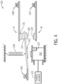
- the switching device may include a relay device 100 that is composed of components illustrated in FIG. 4 , some of which correspond to the components of the switching device described above.
- the relay device 100 shown in FIG. 4 is a Form C relay device 100, it should be understood that the techniques described herein that refer to the Form C relay device 100 are exemplary.
- the relay device may be a Form A relay device, a Form B relay device, a single-pole, single-throw double-break relay device, or any other suitable type of relay device in which an at least partially welded contact may be detected.
- the relay device 100 may include an armature 102 that is coupled to a spring 104.
- the armature 102 may have a common contact 106 that may be coupled to a part of an electrical circuit.
- the armature 102 may electrically couple the common contact 106 to a contact 108 or to a contact 110 depending on a state (e.g., energized) of the relay device 100.
- a state e.g., energized
- the relay coil 112 of the relay device 100 is not energized or does not receive voltage from a driving circuit
- the armature 102 is positioned such that the common contact 106 and the contact 108 are electrically coupled to each other.
- the relay coil 112 receives a driving voltage
- the relay coil 112 magnetizes and attracts the armature 102 to itself, thereby connecting the contact 110 to the common contact 106.
- the electrical connections between the common contact 106 and the contacts 108 and 110 are made via contacts 114 and 116 and contacts 118 and 120, respectively.
- the conductive material of the contacts 114, 116, 118, and 120 may begin to wear.
- the contacts 114 and 116 and the contacts 118 and 120 strike against each other, the contacts may weld in a failed state. In this failed state, the armature 102 may be held in a mostly closed position.
- the relay coil 112 may include a core that maintains a core flux during the operation of the relay device 100. That is, as the armature 102 moves between connecting to the contact 108 and the contact 110, and vice-versa, a magnetic flux may be generated in a core of the relay coil 112 and/or the armature 102. This magnetic flux may be related to the core flux of the relay coil 112 and may change over time as the relay device operates.
- the relay coil 112 may also one include or more sensors 124 that monitor (e.g., measure) the characteristics (e.g., voltage or current) of the relay coil 112 after pinging the relay coil 112 with a non-intrusive voltage pulse or a non-intrusive current pulse. Accordingly, the sensors 124 may include voltage sensors and/or current sensors. The characteristics of the relay coil measured by the sensors 124 may be communicated to the control and monitoring circuitry 18 and used as the basis for determining whether the contact 114, 118 of the relay device 100 is at least partially welded to a corresponding contact 116, 120 of the electrical circuit.
- sensors 124 may include voltage sensors and/or current sensors. The characteristics of the relay coil measured by the sensors 124 may be communicated to the control and monitoring circuitry 18 and used as the basis for determining whether the contact 114, 118 of the relay device 100 is at least partially welded to a corresponding contact 116, 120 of the electrical circuit.
- FIG. 5 illustrates a current-time graph 130 that depicts an exemplary current profile 132 associated with a relay coil 112 during the turn-on sequence of a respective relay device 100. As shown in FIG.
- the exemplary current profile 132 includes an application of a driving voltage to the relay coil 112 during a period of time 134 (i.e., from 0 milliseconds (ms) to approximately 1.5 ms).
- the period of time 134 may correspond to the relay coil 112 receiving the driving voltage from the power source 12 and magnetizing, thereby attracting the armature 102 to the relay coil 112.
- the armature 102 may begin to move toward the relay coil 112 between 1 ms and 1.5 ms after the relay coil 112 receives the driving voltage.
- the relay coil 112 of the relay device 100 may be pinged with a non-intrusive voltage pulse or a non-intrusive current pulse.
- FIGS. 6 and 7 are described with reference to determining whether the contacts 118 and 120 are at least partially welded together. However, it should be understood that the techniques described herein may also be used to determine whether the contacts 114 and 116 are at least partially welded together.
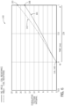
- FIG. 6 illustrates a cumulative voltage integral-time graph 140 that depicts various coil voltage responses 141 and 142 associated with respective relay devices (e.g., 100) that are driven using a fixed current profile during a period of time (e.g., 134).
- the coil voltage responses 141 and 142 may correspond to a relay device 100 having a non-welded contact 118 (e.g., non-welded coil voltage response 141) or an at least partially welded contact 118 (e.g., at least partially welded coil voltage response 142).
- the control and monitoring circuitry 18 may instruct the power source 122 to ping the relay coil 112 of the relay device 100 with a fixed current profile.
- the fixed current profile may be stored in the memory 20 or any other suitable storage device.
- the fixed current profile may correspond to the exemplary current profile 132 illustrated in FIG. 5 during the time period 134.
- any suitable fixed current profile may be used to ping the relay coil 112 in order to determine whether the relay device 100 has an at least partially welded contact or a welded contact before the armature 102 begins to move toward the relay coil 112.
- the fixed current profile may be maintained using a control loop via an H-bridge circuit or the like.
- the power source 122 may include a direct current (DC) voltage power source.
- the sensors 124 may measure the instantaneous voltage of the relay coil 112, and transmit the instantaneous voltage measurements associated with the relay coil 112 to the control and monitoring circuitry 18.
- the control and monitoring circuitry 18 may then determine the cumulative voltage integral of the relay coil 112 over time based on the received instantaneous voltage measurements associated with the relay coil 112 For example, the control and monitoring circuitry 18 may calculate a first data point 144 or 146 for a coil voltage response 141 or 142 of the relay coil 112. As no time has passed from t 0 , it may be appreciated that the cumulative voltage integral(s) at to (i.e., data points 144 and 146) will equal zero until more time has passed.
- the sensors 124 may continuously measure the instantaneous voltage of the relay coil 112.
- a final data point 148 or 150 may be generated by the control and monitoring circuitry 18 at time tr. Accordingly, the control and monitoring circuitry 18 may calculate the cumulative voltage integral up to time tr, thus generating the voltage response 141 or 142 for the relay coil 112.
- the final time tr may correspond to the end of the period of time 134 during a turn-on sequence of the relay device 100.
- the final time t f may be 1.5 ms after the relay coil 112 is pinged with the fixed current profile, 1.25 ms after the relay coil 112 is pinged with the fixed current profile, 1 ms after the relay coil 112 is pinged with the fixed current profile, or any other suitable time period after the relay coil 112 is pinged with the fixed current profile to determine whether the relay coil 112 has one or more welded contacts or not
- the coil voltage responses 141 or 142 of the relay coil 112 may correspond to the relay device 100 having a non-welded contact 118 (e.g., non-welded coil voltage response 141) or an at least partially welded contact 118 (e.g., welded coil voltage response 142).
- the inductance of the relay coil 112 of the relay device 100 having an at least partially welded contact 118 is greater than the inductance of the relay coil 112 of the relay device 100 having no welded contacts (e.g., as illustrated by the coil voltage response 141).
- a determination may be made as to whether the relay device 100 has an at least partially welded contact 118 or no welded contacts 118.
- a baseline coil voltage response (e.g., coil voltage response 141 or 142) may be determined for the relay device 100 before one or more additional voltage measurements of the relay coil 112 are detected for the relay device 100 and compared to the baseline coil voltage response. If the additional voltage measurements of the relay coil 112 are similar to the coil voltage response 141, the additional voltage measurements may indicate that the relay device 100 has no welded contacts 118. Alternatively, if the additional voltage measurements of the relay coil 112 are similar to the coil voltage response 142, the additional voltage measurements may indicate that the relay device 100 has an at least partially welded contact 118.
- the additional voltage measurements may indicate that the relay device 100 has an at least partially welded contact 118 if the additional voltage measurements are outside a first threshold of the coil voltage response 141 or within a second threshold of the coil voltage response 142, or the additional voltage measurements may indicate that the relay device 100 has no welded contacts 118 if the additional voltage measurements are within a third threshold of the coil voltage response 141 or outside a fourth threshold of the coil voltage response 142.
- the first threshold, the second threshold, the third threshold, the fourth threshold, or a combination thereof may be less than or equal to five percent, less than or equal to ten percent, less than or equal to fifteen percent, less than or equal to twenty percent, or the like, of the corresponding coil voltage response 141, 142.
- the first threshold, the second threshold, the third threshold, the fourth threshold, or a combination thereof may be greater than or equal to five percent, greater than or equal to ten percent, greater than or equal to fifteen percent, greater than or equal to twenty percent, or the like, of the corresponding coil voltage response 141, 142.
- the additional voltage measurements may indicate that the relay device 100 has an at least partially welded contact 118 if the additional voltage measurements are greater than one or more corresponding values of the coil voltage response 141, or the additional voltage measurements may indicate the relay device 100 has no welded contacts 118 if the additional voltage measurements are less than one or more corresponding values of the coil voltage response 142.
- FIG. 7 is a flow chart of a process 160 for determining whether a contact 118 of a relay device (e.g., 100) is at least partially welded based on coil voltage measurements associated with the relay device 100 and performing a system response based upon the determination. As described above, it may be desirable to detect whether the relay device 100 has an at least partially welded contact 118 before the armature 102 of the relay device 100 begins to move toward the relay coil 112 during the turn-on sequence of the relay device 100.
- a relay device e.g., 100
- the process 160 may be performed in parallel with the turn-on sequence of the relay device 100 (i.e., before the armature 102 of the relay device 100 begins to move toward the relay coil 112 during the turn-on sequence) or at any other suitable time. It should be noted that although the process 160 will be described as being performed by the control and monitoring circuitry 18, it should be understood that the process 160 may be performed by any suitable control system or computing device (e.g., the controller 44). In addition, although the process 160 is described in a particular order, it should be noted that the process 160 may be performed in any suitable order.
- the control and monitoring circuitry 18 may instruct (e.g., send a command signal to) the power source 122 to send a pulse with a fixed current profile to the relay coil 112 of the relay device 100 at an initial time t 0 .
- the magnitude of the fixed current profile associated with the pulse may be predetermined (i.e., previously stored in the memory 20 of the control and monitoring circuitry 18).
- the fixed current profile may correspond to the exemplary current profile 132 illustrated in FIG. 5 during the time period 134 of the turn-on sequence.
- the fixed current profile may be associated with a baseline coil voltage response 141 associated with the relay device 100 having a non-welded state (i.e., having no welded contacts) and/or a baseline coil voltage response 142 associated with the relay device 100 having an at least partially welded state (i.e., having an at least partially welded contact). That is, the baseline coil voltage responses 141, 142 associated with the relay device 100 may be determined at some time before the control and monitoring circuitry 18 instructs the power source 122 to send the pulse to the relay coil 112 at block 162.
- the control and monitoring circuitry 18 may receive one or more voltage measurements of the relay coil 112 from the sensors 124 at block 164.
- the sensors 124 may generate the voltage measurements at a predetermined rate.
- the sensors 124 may measure the voltage of the relay coil 112 (i.e., the coil voltage) at a certain rate (e.g., n samples per m milliseconds). In this way, the control and monitoring circuitry 18 may receive one or more coil voltage measurements associated with the relay device 100 over the time period.
- the control and monitoring circuitry 18 may optionally log the coil voltage measurements as a function of time.
- the control and monitoring circuitry 18 may store the coil voltage measurements in the memory 20 or any other suitable storage device.
- the control and monitoring circuitry 18 may receive coil voltage measurements until an appropriate condition is present (e.g., after a sufficient number of samples has been logged, t f has been reached, etc.).
- the control and monitoring circuitry 18 may receive coil voltage measurements from the initial time t 0 to any time tr. That is, the time period between the initial time t 0 and t f may be any suitable time period to receive coil voltage measurements associated with the relay device 100.
- the time period may be less than or equal to 1.5 ms after pinging the relay coil 112 with the fixed current profile, less than or equal to 1.25 ms after pinging the relay coil 112 with the fixed current profile, or less than or equal to 1 ms after pinging the relay coil 112 with the fixed current profile.
- the control and monitoring circuitry 18 may determine whether the coil voltage measurements indicate that the relay device 100 includes an at least partially welded contact 118 at block 166.
- one or more baseline coil voltage responses associated with the relay device 100 or a type associated with the relay device 100 may be determined during a time period before implementation of the process 160 by the control and monitoring circuitry 18
- the control and monitoring circuitry 18 may determine a baseline coil voltage response of the relay coil 112 that corresponds to the relay device 100 having no welded contacts.
- the control and monitoring circuitry 18 may receive one or more coil voltage measurements of the relay coil 112 and determine the baseline coil voltage response of the relay coil 112.
- the baseline coil voltage response of the relay coil 112 may then be stored in a memory 20 accessible by the control and monitoring circuitry 18.
- control and monitoring circuitry 18 may retrieve a representation of one or more baseline coil voltage responses associated with the relay device 100 or a type of the relay device 100 from the memory 20.
- the memory 20 may store respective representations of a first baseline coil voltage response that corresponds to the relay device 100 or respective types of various relay devices having no welded contacts 118, respective representations of a second baseline coil voltage response that corresponds to the relay device 100 or respective types of various relay devices having an at least partially welded contact 118.
- the control and monitoring circuitry 18 may retrieve one or more baseline coil voltage responses from the memory 20 that corresponds to the relay device 100 or the type of the relay device (e.g., a Form A relay device, a Form B relay device, a Form C relay device, a single-pole, single-throw double-break relay device, or the like). For example, the control and monitoring circuitry 18 may retrieve the first baseline coil voltage response that corresponds to the relay device 100 having no welded contacts 118, the second baseline coil voltage response that corresponds to the relay device 100 having an at least partially welded contact 118, or both.
- the control and monitoring circuitry 18 may retrieve the first baseline coil voltage response that corresponds to the relay device 100 having no welded contacts 118, the second baseline coil voltage response that corresponds to the relay device 100 having an at least partially welded contact 118, or both.
- control and monitoring circuitry 18 may compare one or more of the coil voltage measurements received at block 164 to a baseline coil voltage response associated with the relay device 100 having no welded contacts 118, a baseline coil voltage response associated with the relay device 100 having an at least partially welded contact 118, or both. As mentioned above, if the coil voltage measurements differ from the baseline coil voltage response associated with the relay device 100 having no welded contacts 118, the control and monitoring circuitry 18 may determine that the coil voltage measurements are indicative of an at least partially welded contact 118 in the relay device 100.
- the control and monitoring circuitry 18 may determine that the coil current measurements are indicative of no welded contacts 118 in the relay device 100. For example, the control and monitoring circuitry 18 may determine that the relay device 100 has an at least partially welded contact 118 if the coil voltage measurements are outside of a threshold associated with the baseline coil voltage response that corresponds to the relay device 100 having no welded contacts 118 if the coil voltage measurements are within a threshold associated with the baseline coil voltage response that corresponds to the relay device 100 having an at least partially welded contact 118.
- control and monitoring circuitry 18 may determine that the relay device 100 has no welded contacts 118 if the coil voltage measurements are outside of a threshold associated with the baseline coil voltage response that corresponds to the relay device 100 having an at least partially welded contact 118 or if the coil voltage measurements are within a threshold associated with the baseline coil voltage response that corresponds to the relay device 100 having no welded contacts 118.
- control and monitoring circuitry 18 may determine that the relay device 100 has an at least partially welded contact 118 if the coil voltage measurements are greater than corresponding values of the baseline coil voltage response that corresponds to the relay device 100 having no welded contacts 118, or the control and monitoring circuitry 18 may determine that the relay device 100 has no welded contacts 118 if the coil voltage measurements are less than corresponding values of the baseline coil voltage response that corresponds to the relay device 100 having an at least partially welded contact 118.
- control and monitoring circuitry 18 may perform a system response that corresponds to the relay device 100 not including an at least partially welded contacts (i.e., the relay device 100 having a non-welded state) at block 168.
- the system response for a non-welded state associated with the relay device 100 may allow the relay device 100 to continue operating normally. For instance, if a turn-on sequence associated with the relay device 100 was being performed, the turn-on sequence may continue such that the armature 102 of the relay device 100 is attracted to the relay coil 112 to close the relay device 100 and connect electric power to a load.
- the control and monitoring circuitry 18 may perform a system response that corresponds to the relay device 100 including the at least partially welded contact (i.e., the relay device 100 having a welded state) at block 170.
- the system response for a welded state associated with the relay device 100 may direct the control and monitoring circuitry 18 to transmit a command to the relay device 100 or the power source 12 to shut down the relay device 100.
- control and monitoring circuitry 18 may transmit a command to display a failure notification, such as via a light emitting diode (LED), a graphical user interface (GUI), or the like. Additionally, or alternatively, the control and monitoring circuitry 18 may transmit a notification of the welded state associated with the relay device 100 to one or more computing devices via a network 21.
- a failure notification such as via a light emitting diode (LED), a graphical user interface (GUI), or the like.
- GUI graphical user interface
- the relay coil 112 of the relay device may be pinged with a non-intrusive current pulse (i.e., instead of the non-intrusive voltage pulse as discussed above with respect to FIGS. 6 and 7 ).
- the control and monitoring circuitry 18 may determine whether a contact of a relay device 100 (e.g., 100) is at least partially welded based on coil current measurements associated with the relay device 100 and perform a system response based upon the determination.
- the control and monitoring circuitry 18 may determine whether a contact of the relay device 100 is at least partially weleded and perform a system response based upon the determination in parallel with the turn-on sequence of the relay device 100 (i.e., before the armature 102 of the relay device 100 begins to move toward the relay coil 112 during the turn-on sequence) or at any other suitable time.
- the control and monitoring circuitry 18 may perform any suitable control system or computing device (e.g., the controller 44).
- the control and monitoring circuitry 18 may instruct (e.g., send a command signal to) the power source 122 to send a pulse with a fixed voltage profile to the relay coil 112 of the relay device 100 at an initial time t 0 .
- the magnitude of the fixed voltage profile associated with the pulse may be predetermined (i.e., previously stored in the memory 20 of the control and monitoring circuitry 18).
- the fixed voltage profile may correspond to a step load.
- the fixed voltage profile may be associated with a baseline coil current response associated with the relay device 100 having a non-welded state (i.e., having no welded contacts), a baseline coil current profile response associated with the relay device 100 having a welded state (i.e., having an at least partially welded contact), or both. That is, the baseline coil current responses associated with the relay device 100 may be determined at some time before the control and monitoring circuitry 18 instructs the power source 122 to send the pulse to the relay coil 112.
- the control and monitoring circuitry 18 may then receive one or more current voltage measurements of the relay coil 112 from the sensors 124 during a period of time (e.g., from initial time t 01 to final time t f ).
- the sensors 124 may generate the current measurements at a predetermined rate.
- the sensors 124 may measure the current of the relay coil 112 (i.e., the coil current) at a certain rate (e.g., n samples per m milliseconds). In this way, the control and monitoring circuitry 18 may receive one or more coil voltage measurements associated with the relay device 100 over the time period.
- the time period may be less than or equal to 1.5 ms after pinging the relay coil 112 with the fixed current profile, less than or equal to 1.25 ms after pinging the relay coil 112 with the fixed current profile, or less than or equal to 1 ms after pinging the relay coil 112 with the fixed current profile.
- control and monitoring circuitry 18 may optionally log the coil current measurements as a function of time.
- the control and monitoring circuitry 18 may store the coil current measurements in the memory 20 or any other suitable storage device.
- the control and monitoring circuitry 18 may receive coil current measurements until an appropriate condition is present (e.g., after a sufficient number of samples has been logged, t f1 has been reached, etc.).
- the control and monitoring circuitry 18 may determine whether the coil current measurements associated with the relay device 100 indicate that the relay device 100 includes an at least partially welded contact 118.
- one or more baseline coil current responses associated with the relay device 100 or a type associated with the relay device 100 may be previously determined during a time period by the control and monitoring circuitry 18.
- the control and monitoring circuitry 18 may determine a baseline coil current response of the relay coil 112 that corresponds to the relay device 100 having no welded contacts 118.
- the control and monitoring circuitry 18 may receive one or more coil current measurements of the relay coil 112 and determine the baseline coil current response of the relay coil 1 12.
- the baseline coil current response of the relay coil 112 may then be stored in a memory 20 accessible by the control and monitoring circuitry 18.
- control and monitoring circuitry 18 may retrieve a representation of one or more baseline coil voltage responses associated with the relay device 100 or a type of the relay device 100 from the memory 20.
- the memory 20 may store respective representations of a first baseline coil current response that corresponds to the relay device 100 or respective types of various relay devices having no welded contacts, respective representations of a second baseline coil current response that corresponds to the relay device 100 or respective types of various relay devices having an at least partially welded contact 118.
- the control and monitoring circuitry 18 may retrieve one or more baseline coil current responses from the memory 20 that corresponds to the relay device 100 or the type of the relay device (e.g., a Form A relay device, a Form B relay device, a Form C relay device, a single-pole, single-throw double-break relay device, or the like). For example, the control and monitoring circuitry 18 may retrieve the first baseline coil current response that corresponds to the relay device 100 having no welded contacts 118, the second baseline coil current response that corresponds to the relay device 100 having an at least partially welded contact 118, or both.
- the control and monitoring circuitry 18 may retrieve the first baseline coil current response that corresponds to the relay device 100 having no welded contacts 118, the second baseline coil current response that corresponds to the relay device 100 having an at least partially welded contact 118, or both.
- control and monitoring circuitry 18 may compare one or more of the received coil current measurements to a baseline coil current response associated with the relay device 100 having no welded contacts 118, a baseline coil current response associated with the relay device 100 having an at least partially welded contact 118, or both. As mentioned above, if the coil current measurements differ from the baseline coil current response associated with the relay device 100 having no welded contacts 118, the control and monitoring circuitry 18 may determine that the coil current measurements are indicative of an at least partially welded contact 118 in the relay device 100.
- the control and monitoring circuitry 18 may determine that the coil current measurements are indicative of no welded contacts 118 in the relay device 100. For example, the control and monitoring circuitry 18 may determine that the relay device 100 has an at least partially welded contact 118 if the coil current measurements are outside of a threshold associated with the baseline coil current response that corresponds to the relay device 100 having no welded contacts 118 if the coil current measurements are within a threshold associated with the baseline coil current response that corresponds to the relay device 100 having an at least partially welded contact 118.
- control and monitoring circuitry 18 may determine that the relay device 100 has no welded contacts 118 if the coil current measurements are outside of a threshold associated with the baseline coil current response that corresponds to the relay device 100 having an at least partially welded contact 118 or if the coil current measurements are within a threshold associated with the baseline current response that corresponds to the relay device 100 having no welded contacts 118.
- control and monitoring circuitry 18 may determine that the relay device 100 has an at least partially welded contact 118 if the coil current measurements are greater than corresponding values of the baseline coil current response that corresponds to the relay device 100 having no welded contacts 118, or the control and monitoring circuitry 18 may determine that the relay device 100 has no welded contacts 118 if the coil current measurements are less than corresponding values of the baseline coil current response that corresponds to the relay device 100 having an at least partially welded contact 118.
- the control and monitoring circuitry 18 may perform a system response that corresponds to the relay device 100 not including an at least partially welded contact (i.e., the relay device 100 having a non-welded state).
- the system response for a non-welded state associated with the relay device 100 may allow the relay device 100 to continue operating normally. For instance, if a turn-on sequence associated with the relay device 100 was being performed, the turn-on sequence may continue such that the armature 102 of the relay device 100 is attracted to the relay coil 112 to close the relay device 100 and connect electric power to a load.
- the control and monitoring circuitry 18 may log the non-welded state associated with the relay device 100 in the memory 20 or any other suitable storage device.
- the control and monitoring circuitry 18 may perform a system response that corresponds to the relay device 100 including an at least partially welded contact (i.e., the relay device 100 having a welded state).
- the system response for a welded state associated with the relay device 100 may direct the control and monitoring circuitry 18 to transmit a command to the relay device 100 or the power source 12 to shut down the relay device 100. For instance, if a turn-on sequence associated with the relay device 100 was being performed, the turn-on sequence may be shut down before the armature 102 of the relay device 100 moves toward the relay coil 112.
- control and monitoring circuitry 18 may transmit a command to display a failure notification, such as via a light emitting diode (LED), a graphical user interface (GUI), or the like. Additionally, or alternatively, the control and monitoring circuitry 18 may transmit a notification of the welded state associated with the relay device 100 to one or more computing devices via a network 21. In some embodiments, the control and monitoring circuitry 18 may log the welded event in the memory 20 or any other suitable storage device.
- a failure notification such as via a light emitting diode (LED), a graphical user interface (GUI), or the like.
- the control and monitoring circuitry 18 may transmit a notification of the welded state associated with the relay device 100 to one or more computing devices via a network 21. In some embodiments, the control and monitoring circuitry 18 may log the welded event in the memory 20 or any other suitable storage device.
- the control and monitoring circuitry 18 may optionally instruct the power source 122 to transmit a pulse with a reverse voltage profile to the relay coil 112.
- the pulse with the reverse voltage profile may be equal in magnitude to the fixed voltage profile that was transmitted to the relay coil 112.
- the control and monitoring circuitry 18 may instruct the power source 122 to transmit the pulse with the reverse voltage profile for a period of time substantially equal to the time period associated with the fixed voltage profile.
- the relay coil 112 may be pinged with the pulse associated with the reverse voltage profile for a time period of t 02 to t f2 that may be substantially similar in duration as the time period of toi to t f1 .
- control and monitoring circuitry 18 may receive a baseline coil voltage response associated with the relay device 100 having no welded contacts 118 or a baseline coil current response associated with the relay device 100 having no welded contacts 118. The control and monitoring circuitry 18 may then determine that the relay device 100 has an at least partially welded contact 118 or no welded contacts 118 if one or more voltage measurements or one or more current measurements associated with the relay coil 112 are within a threshold associated with the baseline coil voltage response or a threshold associated with the baseline coil current response, respectively. Under certain conditions, however, the ambient temperature of the relay coil 112 may affect the coil resistance of the relay coil 112, thereby influencing voltage measurements or current measurements of the relay coil 112. Thus, the control and monitoring circuity 18 may compensate for changes in the ambient temperature of the relay coil 112 during implementation of the techniques described herein,
- control and monitoring circuitry 18 may measure the coil resistance of the relay coil 112 before power is provided to the relay coil 112. For example, control and monitoring circuitry 18 may receive an ambient temperature associated with the relay coil 112 from one or more sensors (e.g., sensors 124). Based on the ambient temperature measurement, the control and monitoring circuitry 18 may determine a coil resistance of the relay coil 1 12 based on a first linear relationship between the ambient temperature and the initial coil resistance of the relay coil 112.
- control and monitoring circuitry 18 may adjust the thresholds associated with the baseline coil voltage response and/or the baseline coil current response based on a second linear relationship between the thresholds and the coil resistance. For example, the control and monitoring circuitry may increase or decrease the thresholds based on the coil resistance of the relay coil 112. In this way, the control and monitoring circuitry 18 may compensate for fluctuations in the ambient temperature surrounding the relay coil 112.
- control and monitoring circuitry 18 may receive an ambient temperature associated with the relay coil 112 from one or more sensors (e.g., sensors 124) before or in parallel with the control and monitoring circuitry 18 transmitting the command to the power source 122 to send the pulse with the fixed voltage profile or the fixed current profile to the relay coil 112. In such embodiments, the control and monitoring circuitry 18 may directly adjust the thresholds associated with the baseline coil voltage response and/or the baseline coil current response before determining whether the voltage measurements or the current measurements of the relay coil 112 are indicative of an at least partially welded contact.
- welded contacts may be detected without signals or sensors crossing the isolation barrier between the relay coil 112 and the contacts 114 and 116 or the contacts 118 and 120.
- the embodiments disclosed herein allow for detecting welded contacts without turning on the relay device (i.e., without applying power to the system 10).
- electrical and mechanical safety issues associated with welded contacts within relay devices may be reduced in a non-intrusive manner, thereby improving relay device performance without adding a significant amount of complexity to the system 10 and the relay device 100.
- some switching or relay devices may include more than one coil.
- some relay devices may have two coils, such that both coils may be used to control the movement of an armature. In these types of relay devices, one of the coils may be used to hold the armature in place after it moves to a particular position.
Landscapes
- Physics & Mathematics (AREA)
- Electromagnetism (AREA)
- Relay Circuits (AREA)
Claims (13)
- Ein System, aufweisend:eine erste Stromquelle (12); undeine Schaltvorrichtung (100), umfassend:einen Anker (102), der so konfiguriert ist, dass er einen oder mehrere bewegliche Kontakte (114, 118) mit einem oder mehreren Kontakten (116, 120) einer elektrischen Schaltung elektrisch koppelt;eine Spule (112), die so konfiguriert ist, dass sie einen Strom von einer zweiten Energiequelle (122) empfängt, wodurch der Anker veranlasst wird, den einen oder die mehreren beweglichen Kontakte mit dem einen oder den mehreren Kontakten der elektrischen Schaltung elektrisch zu koppeln oder den einen oder die mehreren beweglichen Kontakte von dem einen oder den mehreren Kontakten nach einer Zeitspanne (134) elektrisch zu trennen; undein Steuersystem (18), das so konfiguriert ist, dass es Vorgänge durchführt, die Folgendes umfassen:Übertragen eines Befehls an die zweite Stromquelle, um die Spule mit einem festen Stromprofil mit Strom zu versorgen (132), wobei der Befehl an die Stromquelle, die Spule mit Strom zu versorgen, während einer Einschaltsequenz der Schaltvorrichtung übertragen wird;Empfangen einer oder mehrerer Spannungsmessungen (141, 142), die mit der Spule während der Zeitperiode verbunden sind;Bestimmen, dass die eine oder mehreren Spannungsmessungen anzeigen, dass der eine oder die mehreren beweglichen Kontakte zumindest teilweise mit dem einen oder den mehreren Kontakten der elektrischen Schaltung verschweißt sind; undals Reaktion auf die Feststellung, dass die eine oder die mehreren Spannungsmessungen (142) anzeigen, dass der eine oder die mehreren beweglichen Kontakte zumindest teilweise mit dem einen oder den mehreren Kontakten der elektrischen Schaltung verschweißt sind, Übertragen eines zusätzlichen Befehls an die zweite Energiequelle, um den Strom zur Spule zu unterbrechen, wobei der zusätzliche Befehl zum Unterbrechen des Stroms zur Spule an die zweite Energiequelle übertragen wird, bevor der Anker den einen oder die mehreren beweglichen Kontakte mit dem einen oder den mehreren Kontakten der elektrischen Schaltung elektrisch koppelt oder den einen oder die mehreren beweglichen Kontakte von dem einen oder den mehreren Kontakten elektrisch trennt.
- Das System nach Anspruch 1, wobei die Bestimmung, dass die eine oder mehreren Spannungsmessungen anzeigen, dass der eine oder die beweglichen Kontakte zumindest teilweise mit dem einen oder den mehreren Kontakten des Stromkreises verschweißt sind, Folgendes umfasst:Empfangen einer oder mehrerer Basislinien-Spannungsantworten, die mit der Relaisspule verbunden sind; undBestimmen, dass die eine oder mehreren Spannungsmessungen von den jeweiligen Werten der einen oder mehreren Grundlinien-Spannungsantworten abweichen.
- Das System nach Anspruch 2, wobei die eine oder mehreren Basislinien-Spannungsantworten mit einem nicht verschweißten Zustand der Schaltvorrichtung verbunden sind.
- Das System nach Anspruch 3, wobei die Bestimmung, dass die eine oder mehreren Spannungsmessungen von den jeweiligen Werten der einen oder mehreren Grundlinien-Spannungsantworten abweichen, die Bestimmung umfasst, dass die eine oder mehreren Spannungsmessungen größer sind als die jeweiligen Werte der einen oder mehreren Grundlinien-Spannungsantworten.
- Das System nach Anspruch 2, wobei die eine oder die mehreren Grundlinien-Spannungsantworten mit einem geschweißten Zustand der Schaltvorrichtung verbunden sind.
- Das System nach Anspruch 5, wobei die Bestimmung, dass die eine oder mehreren Spannungsmessungen von den jeweiligen Werten der einen oder mehreren Grundlinien-Spannungsantworten abweichen, die Bestimmung umfasst, dass die eine oder mehreren Spannungsmessungen innerhalb eines Schwellenwerts der einen oder mehreren Grundlinien-Spannungsantworten liegen.
- Ein Verfahren, aufweisend:Übertragen (162) eines Befehls zur Versorgung einer Spule (112) der Schaltvorrichtung mit einem festen Stromprofil (132) durch ein Steuersystem (18) an eine erste Stromquelle (122), die einer Schaltvorrichtung (100) zugeordnet ist, wobei der Befehl an die Stromquelle zur Versorgung der Spule mit Strom während einer Einschaltsequenz der Schaltvorrichtung übertragen wird;Empfangen (164), durch das Steuersystem, einer oder mehrerer Spannungsmessungen (141, 142), die mit der Spule während einer Zeitperiode verbunden sind;Bestimmen (166) durch das Steuersystem, dass eine oder mehrere Spannungsmessungen (142) anzeigen, dass ein oder mehrere bewegliche Kontakte (114, 118) der Schaltvorrichtung zumindest teilweise mit einem oder mehreren Kontakten (116, 120) einer elektrischen Schaltung verschweißt sind; undals Reaktion auf die Feststellung, dass die eine oder die mehreren Spannungsmessungen anzeigen, dass der eine oder die mehreren beweglichen Kontakte der Schaltvorrichtung zumindest teilweise mit dem einen oder den mehreren Kontakten der elektrischen Schaltung verschweißt sind, Übertragen (170) eines zusätzlichen Befehls an eine zweite Stromquelle durch das Steuersystem, um einen Strom zur Spule zu unterbrechen, wobei der zusätzliche Befehl zum Unterbrechen des Stroms zur Spule an die zweite Stromquelle übertragen wird, bevor der Anker den einen oder die mehreren beweglichen Kontakte mit dem einen oder den mehreren Kontakten der elektrischen Schaltung elektrisch koppelt oder den einen oder die mehreren beweglichen Kontakte von dem einen oder den mehreren Kontakten elektrisch trennt.
- Das Verfahren nach Anspruch 7, wobei die Bestimmung, dass die eine oder mehreren Spannungsmessungen anzeigen, dass der eine oder die mehreren beweglichen Kontakte zumindest teilweise mit dem einen oder den mehreren Kontakten des Stromkreises verschweißt sind, Folgendes umfasst:Empfangen einer oder mehrerer Basislinien-Spannungsantworten, die mit der Relaisspule verbunden sind; undBestimmen, dass die eine oder mehreren Spannungsmessungen von den jeweiligen Werten der einen oder mehreren Grundlinien-Spannungsantworten abweichen.
- Das Verfahren nach Anspruch 8, wobei die eine oder die mehreren Basislinien-Spannungsantworten mit einem geschweißten Zustand der Schaltvorrichtung verbunden sind.
- Das Verfahren nach Anspruch 9, wobei das Bestimmen, dass sich die eine oder mehreren Spannungsmessungen von den jeweiligen Werten der einen oder mehreren Grundlinien-Spannungsantworten unterscheiden, das Bestimmen umfasst, dass die eine oder mehreren Spannungsmessungen innerhalb eines Schwellenwerts der einen oder mehreren Grundlinien-Spannungsantworten liegen, wobei das Verfahren vorzugsweise ferner das Einstellen des Schwellenwerts der einen oder mehreren Grundlinien-Spannungsantworten auf der Grundlage einer der Spule zugeordneten Umgebungstemperatur durch das Steuersystem und das Empfangen einer Messung der der Spule zugeordneten Umgebungstemperatur durch das Steuersystem vor dem Übertragen des Befehls an die erste Stromquelle zur Bereitstellung von Strom für die Spule der Schaltvorrichtung mit dem festen Stromprofil umfasst.
- Das Verfahren nach einem der Ansprüche 7 bis 10, umfassend mindestens einen der folgenden Schritte:Bestimmen eines Spulenwiderstands der Spule durch das Steuersystem auf der Grundlage einer oder mehrerer zusätzlicher Spannungsmessungen, die mit der Spule verbunden sind, und einer oder mehrerer Strommessungen, die mit der Spule verbunden sind, und Einstellen des Schwellenwerts der einen oder mehreren Grundlinien-Spannungsantworten auf der Grundlage des Spulenwiderstands durch das Steuersystem; undÜbertragen einer Benachrichtigung, die den geschweißten Zustand der Schaltvorrichtung anzeigt, an eine oder mehrere Rechenvorrichtungen.
- Ein nicht-transitorisches, computerlesbares Medium, das Befehle speichert, die von mindestens einem Prozessor in einer Rechenvorrichtung ausführbar sind, wobei die Befehle Befehle umfassen, um den mindestens einen Prozessor zu veranlassen, Operationen durchzuführen, die umfassenÜbertragen eines Befehls an eine erste Stromquelle (122), die mit einer Schaltvorrichtung (100) verbunden ist, um eine Spule (112) der Schaltvorrichtung mit einem festen Stromprofil (132) mit Strom zu versorgen, wobei der Befehl an die Stromquelle, die Spule mit Strom zu versorgen, während einer Einschaltsequenz der Schaltvorrichtung übertragen wird;Empfangen einer oder mehrerer Spannungsmessungen (141, 142), die der Spule während einer Zeitspanne zugeordnet sind;Bestimmen, ob die eine oder die mehreren Spannungsmessungen, die mit der Spule verbunden sind, anzeigen, dass ein oder mehrere bewegliche Kontakte (114, 118) der Schaltvorrichtung zumindest teilweise mit einem oder mehreren Kontakten (116, 120) einer elektrischen Schaltung verschweißt sind; undals Reaktion auf die Feststellung, dass die eine oder mehreren der Spule zugeordneten Spannungsmessungen (142) anzeigen, dass ein oder mehrere bewegliche Kontakte der Schaltvorrichtung zumindest teilweise mit einem oder mehreren Kontakten einer elektrischen Schaltung verschweißt sind, Übertragen eines zusätzlichen Befehls an eine zweite Stromquelle, um einen Strom zur Spule zu unterbrechen, wobei der zusätzliche Befehl zum Unterbrechen des Stroms zur Spule an die zweite Stromquelle übertragen wird, bevor der Anker den einen oder die mehreren beweglichen Kontakte mit dem einen oder den mehreren Kontakten der elektrischen Schaltung elektrisch koppelt oder den einen oder die mehreren beweglichen Kontakte von dem einen oder den mehreren Kontakten elektrisch trennt.
- Das Nicht-transitorische, computerlesbare Medium nach Anspruch 12,
wobei die Schaltvorrichtung so konfiguriert ist, dass sie den Betrieb während einer Einschaltsequenz fortsetzt, wenn festgestellt wird, dass die eine oder die mehreren der Spule zugeordneten Spannungsmessungen anzeigen, dass der eine oder die mehreren beweglichen Kontakte der Schaltvorrichtung nicht mit einem oder mehreren Kontakten des Stromkreises verschweißt sind.
Applications Claiming Priority (1)
| Application Number | Priority Date | Filing Date | Title |
|---|---|---|---|
| US17/485,734 US11901145B2 (en) | 2021-09-27 | 2021-09-27 | Systems and methods for detecting welded contacts in an electromagnetic switch system |
Publications (2)
| Publication Number | Publication Date |
|---|---|
| EP4156221A1 EP4156221A1 (de) | 2023-03-29 |
| EP4156221B1 true EP4156221B1 (de) | 2024-07-24 |
Family
ID=83506700
Family Applications (1)
| Application Number | Title | Priority Date | Filing Date |
|---|---|---|---|
| EP22198007.1A Active EP4156221B1 (de) | 2021-09-27 | 2022-09-27 | Systeme und verfahren zur erkennung geschweisster kontakte in einem elektromagnetischen schaltsystem |
Country Status (2)
| Country | Link |
|---|---|
| US (1) | US11901145B2 (de) |
| EP (1) | EP4156221B1 (de) |
Families Citing this family (3)
| Publication number | Priority date | Publication date | Assignee | Title |
|---|---|---|---|---|
| US12422484B2 (en) | 2023-06-21 | 2025-09-23 | Rockwell Automation Technologies, Inc. | Detecting welded relay contacts using electrical pulse |
| US12461156B2 (en) | 2023-06-21 | 2025-11-04 | Rockwell Automation Technologies, Inc. | Detecting welded relay contacts using spanner voltage measurement |
| US12416672B2 (en) | 2023-06-21 | 2025-09-16 | Rockwell Automation Technologies, Inc. | Detecting welded relay contacts using contact close time measurement |
Family Cites Families (6)
| Publication number | Priority date | Publication date | Assignee | Title |
|---|---|---|---|---|
| SE515261C2 (sv) | 1995-06-12 | 2001-07-09 | Abb Research Ltd | Kontaktorutrustning |
| US5774323A (en) | 1995-10-31 | 1998-06-30 | Eaton Corporation | Detection of contact position from coil current in electromagnetic switches having AC or DC operated coils |
| US6233132B1 (en) | 1998-09-03 | 2001-05-15 | Ranco Incorporated Of Delaware | Zero cross relay actuation method and system implementing same |
| US7417519B2 (en) * | 2004-09-30 | 2008-08-26 | Rockwell Automation Technologies, Inc. | Emergency stop relay combination |
| JP5370553B1 (ja) | 2012-08-31 | 2013-12-18 | オムロン株式会社 | 電磁継電器の溶着検出装置及び電磁継電器の溶着検出方法 |
| JP5660236B1 (ja) | 2014-02-27 | 2015-01-28 | オムロン株式会社 | 電磁継電器の異常検出方法、電磁継電器の異常検出回路、及び、異常検出システム |
-
2021
- 2021-09-27 US US17/485,734 patent/US11901145B2/en active Active
-
2022
- 2022-09-27 EP EP22198007.1A patent/EP4156221B1/de active Active
Also Published As
| Publication number | Publication date |
|---|---|
| US11901145B2 (en) | 2024-02-13 |
| US20230101428A1 (en) | 2023-03-30 |
| EP4156221A1 (de) | 2023-03-29 |
Similar Documents
| Publication | Publication Date | Title |
|---|---|---|
| EP4156221B1 (de) | Systeme und verfahren zur erkennung geschweisster kontakte in einem elektromagnetischen schaltsystem | |
| US12347636B2 (en) | Systems and methods for detecting welded contacts in a switch system | |
| US11651918B2 (en) | Sensing properties of switching devices using back EMF measurements | |
| CN112582214B (zh) | 用于控制接触器弹跳的系统和方法 | |
| US10175298B2 (en) | Wellness monitoring of electromagnetic switching devices | |
| US10074497B2 (en) | Operator coil parameter based electromagnetic switching | |
| US9806642B2 (en) | Modular multiple single-pole electromagnetic switching system and method | |
| US10141143B2 (en) | Wear-balanced electromagnetic motor control switching | |
| US20160134205A1 (en) | Detection of electric motor short circuits | |
| CN112582208B (zh) | 继电器线圈驱动电路 | |
| US20160134208A1 (en) | Torque-based stepwise motor starting | |
| US20160134206A1 (en) | 5-pole based wye-delta motor starting system and method | |
| EP3893259B1 (de) | Systeme und verfahren zur steuerung der offenzeit eines schützes | |
| EP4156218B1 (de) | Vorhersage von nulldurchgangs für paw-schalttechniken | |
| CN107918427B (zh) | 具有电子的线圈驱控系统的接触器 | |
| EP4160643A2 (de) | Systeme und verfahren zur normalisierung von energie mit offenem lichtbogen |
Legal Events
| Date | Code | Title | Description |
|---|---|---|---|
| PUAI | Public reference made under article 153(3) epc to a published international application that has entered the european phase |
Free format text: ORIGINAL CODE: 0009012 |
|
| STAA | Information on the status of an ep patent application or granted ep patent |
Free format text: STATUS: THE APPLICATION HAS BEEN PUBLISHED |
|
| AK | Designated contracting states |
Kind code of ref document: A1 Designated state(s): AL AT BE BG CH CY CZ DE DK EE ES FI FR GB GR HR HU IE IS IT LI LT LU LV MC MK MT NL NO PL PT RO RS SE SI SK SM TR |
|
| STAA | Information on the status of an ep patent application or granted ep patent |
Free format text: STATUS: REQUEST FOR EXAMINATION WAS MADE |
|
| 17P | Request for examination filed |
Effective date: 20230809 |
|
| RBV | Designated contracting states (corrected) |
Designated state(s): AL AT BE BG CH CY CZ DE DK EE ES FI FR GB GR HR HU IE IS IT LI LT LU LV MC MK MT NL NO PL PT RO RS SE SI SK SM TR |
|
| GRAP | Despatch of communication of intention to grant a patent |
Free format text: ORIGINAL CODE: EPIDOSNIGR1 |
|
| STAA | Information on the status of an ep patent application or granted ep patent |
Free format text: STATUS: GRANT OF PATENT IS INTENDED |
|
| INTG | Intention to grant announced |
Effective date: 20240314 |
|
| GRAS | Grant fee paid |
Free format text: ORIGINAL CODE: EPIDOSNIGR3 |
|
| GRAA | (expected) grant |
Free format text: ORIGINAL CODE: 0009210 |
|
| STAA | Information on the status of an ep patent application or granted ep patent |
Free format text: STATUS: THE PATENT HAS BEEN GRANTED |
|
| AK | Designated contracting states |
Kind code of ref document: B1 Designated state(s): AL AT BE BG CH CY CZ DE DK EE ES FI FR GB GR HR HU IE IS IT LI LT LU LV MC MK MT NL NO PL PT RO RS SE SI SK SM TR |
|
| REG | Reference to a national code |
Ref country code: GB Ref legal event code: FG4D |
|
| REG | Reference to a national code |
Ref country code: CH Ref legal event code: EP |
|
| REG | Reference to a national code |
Ref country code: IE Ref legal event code: FG4D Ref country code: DE Ref legal event code: R096 Ref document number: 602022004784 Country of ref document: DE |
|
| REG | Reference to a national code |
Ref country code: LT Ref legal event code: MG9D |
|
| REG | Reference to a national code |
Ref country code: NL Ref legal event code: MP Effective date: 20240724 |
|
| PG25 | Lapsed in a contracting state [announced via postgrant information from national office to epo] |
Ref country code: PT Free format text: LAPSE BECAUSE OF FAILURE TO SUBMIT A TRANSLATION OF THE DESCRIPTION OR TO PAY THE FEE WITHIN THE PRESCRIBED TIME-LIMIT Effective date: 20241125 |
|
| REG | Reference to a national code |
Ref country code: AT Ref legal event code: MK05 Ref document number: 1707134 Country of ref document: AT Kind code of ref document: T Effective date: 20240724 |
|
| PG25 | Lapsed in a contracting state [announced via postgrant information from national office to epo] |
Ref country code: NL Free format text: LAPSE BECAUSE OF FAILURE TO SUBMIT A TRANSLATION OF THE DESCRIPTION OR TO PAY THE FEE WITHIN THE PRESCRIBED TIME-LIMIT Effective date: 20240724 |
|
| PG25 | Lapsed in a contracting state [announced via postgrant information from national office to epo] |
Ref country code: PT Free format text: LAPSE BECAUSE OF FAILURE TO SUBMIT A TRANSLATION OF THE DESCRIPTION OR TO PAY THE FEE WITHIN THE PRESCRIBED TIME-LIMIT Effective date: 20241125 Ref country code: NL Free format text: LAPSE BECAUSE OF FAILURE TO SUBMIT A TRANSLATION OF THE DESCRIPTION OR TO PAY THE FEE WITHIN THE PRESCRIBED TIME-LIMIT Effective date: 20240724 |
|
| PG25 | Lapsed in a contracting state [announced via postgrant information from national office to epo] |
Ref country code: NO Free format text: LAPSE BECAUSE OF FAILURE TO SUBMIT A TRANSLATION OF THE DESCRIPTION OR TO PAY THE FEE WITHIN THE PRESCRIBED TIME-LIMIT Effective date: 20241024 |
|
| PG25 | Lapsed in a contracting state [announced via postgrant information from national office to epo] |
Ref country code: FI Free format text: LAPSE BECAUSE OF FAILURE TO SUBMIT A TRANSLATION OF THE DESCRIPTION OR TO PAY THE FEE WITHIN THE PRESCRIBED TIME-LIMIT Effective date: 20240724 Ref country code: GR Free format text: LAPSE BECAUSE OF FAILURE TO SUBMIT A TRANSLATION OF THE DESCRIPTION OR TO PAY THE FEE WITHIN THE PRESCRIBED TIME-LIMIT Effective date: 20241025 Ref country code: PL Free format text: LAPSE BECAUSE OF FAILURE TO SUBMIT A TRANSLATION OF THE DESCRIPTION OR TO PAY THE FEE WITHIN THE PRESCRIBED TIME-LIMIT Effective date: 20240724 |
|
| PG25 | Lapsed in a contracting state [announced via postgrant information from national office to epo] |
Ref country code: BG Free format text: LAPSE BECAUSE OF FAILURE TO SUBMIT A TRANSLATION OF THE DESCRIPTION OR TO PAY THE FEE WITHIN THE PRESCRIBED TIME-LIMIT Effective date: 20240724 |
|
| PG25 | Lapsed in a contracting state [announced via postgrant information from national office to epo] |
Ref country code: LV Free format text: LAPSE BECAUSE OF FAILURE TO SUBMIT A TRANSLATION OF THE DESCRIPTION OR TO PAY THE FEE WITHIN THE PRESCRIBED TIME-LIMIT Effective date: 20240724 |
|
| PG25 | Lapsed in a contracting state [announced via postgrant information from national office to epo] |
Ref country code: IS Free format text: LAPSE BECAUSE OF FAILURE TO SUBMIT A TRANSLATION OF THE DESCRIPTION OR TO PAY THE FEE WITHIN THE PRESCRIBED TIME-LIMIT Effective date: 20241124 Ref country code: AT Free format text: LAPSE BECAUSE OF FAILURE TO SUBMIT A TRANSLATION OF THE DESCRIPTION OR TO PAY THE FEE WITHIN THE PRESCRIBED TIME-LIMIT Effective date: 20240724 |
|
| PG25 | Lapsed in a contracting state [announced via postgrant information from national office to epo] |
Ref country code: HR Free format text: LAPSE BECAUSE OF FAILURE TO SUBMIT A TRANSLATION OF THE DESCRIPTION OR TO PAY THE FEE WITHIN THE PRESCRIBED TIME-LIMIT Effective date: 20240724 |
|
| PG25 | Lapsed in a contracting state [announced via postgrant information from national office to epo] |
Ref country code: RS Free format text: LAPSE BECAUSE OF FAILURE TO SUBMIT A TRANSLATION OF THE DESCRIPTION OR TO PAY THE FEE WITHIN THE PRESCRIBED TIME-LIMIT Effective date: 20241024 Ref country code: ES Free format text: LAPSE BECAUSE OF FAILURE TO SUBMIT A TRANSLATION OF THE DESCRIPTION OR TO PAY THE FEE WITHIN THE PRESCRIBED TIME-LIMIT Effective date: 20240724 |
|
| PG25 | Lapsed in a contracting state [announced via postgrant information from national office to epo] |
Ref country code: RS Free format text: LAPSE BECAUSE OF FAILURE TO SUBMIT A TRANSLATION OF THE DESCRIPTION OR TO PAY THE FEE WITHIN THE PRESCRIBED TIME-LIMIT Effective date: 20241024 Ref country code: PL Free format text: LAPSE BECAUSE OF FAILURE TO SUBMIT A TRANSLATION OF THE DESCRIPTION OR TO PAY THE FEE WITHIN THE PRESCRIBED TIME-LIMIT Effective date: 20240724 Ref country code: NO Free format text: LAPSE BECAUSE OF FAILURE TO SUBMIT A TRANSLATION OF THE DESCRIPTION OR TO PAY THE FEE WITHIN THE PRESCRIBED TIME-LIMIT Effective date: 20241024 Ref country code: LV Free format text: LAPSE BECAUSE OF FAILURE TO SUBMIT A TRANSLATION OF THE DESCRIPTION OR TO PAY THE FEE WITHIN THE PRESCRIBED TIME-LIMIT Effective date: 20240724 Ref country code: IS Free format text: LAPSE BECAUSE OF FAILURE TO SUBMIT A TRANSLATION OF THE DESCRIPTION OR TO PAY THE FEE WITHIN THE PRESCRIBED TIME-LIMIT Effective date: 20241124 Ref country code: HR Free format text: LAPSE BECAUSE OF FAILURE TO SUBMIT A TRANSLATION OF THE DESCRIPTION OR TO PAY THE FEE WITHIN THE PRESCRIBED TIME-LIMIT Effective date: 20240724 Ref country code: GR Free format text: LAPSE BECAUSE OF FAILURE TO SUBMIT A TRANSLATION OF THE DESCRIPTION OR TO PAY THE FEE WITHIN THE PRESCRIBED TIME-LIMIT Effective date: 20241025 Ref country code: FI Free format text: LAPSE BECAUSE OF FAILURE TO SUBMIT A TRANSLATION OF THE DESCRIPTION OR TO PAY THE FEE WITHIN THE PRESCRIBED TIME-LIMIT Effective date: 20240724 Ref country code: ES Free format text: LAPSE BECAUSE OF FAILURE TO SUBMIT A TRANSLATION OF THE DESCRIPTION OR TO PAY THE FEE WITHIN THE PRESCRIBED TIME-LIMIT Effective date: 20240724 Ref country code: BG Free format text: LAPSE BECAUSE OF FAILURE TO SUBMIT A TRANSLATION OF THE DESCRIPTION OR TO PAY THE FEE WITHIN THE PRESCRIBED TIME-LIMIT Effective date: 20240724 Ref country code: AT Free format text: LAPSE BECAUSE OF FAILURE TO SUBMIT A TRANSLATION OF THE DESCRIPTION OR TO PAY THE FEE WITHIN THE PRESCRIBED TIME-LIMIT Effective date: 20240724 |
|
| PG25 | Lapsed in a contracting state [announced via postgrant information from national office to epo] |
Ref country code: RO Free format text: LAPSE BECAUSE OF FAILURE TO SUBMIT A TRANSLATION OF THE DESCRIPTION OR TO PAY THE FEE WITHIN THE PRESCRIBED TIME-LIMIT Effective date: 20240724 Ref country code: SM Free format text: LAPSE BECAUSE OF FAILURE TO SUBMIT A TRANSLATION OF THE DESCRIPTION OR TO PAY THE FEE WITHIN THE PRESCRIBED TIME-LIMIT Effective date: 20240724 Ref country code: DK Free format text: LAPSE BECAUSE OF FAILURE TO SUBMIT A TRANSLATION OF THE DESCRIPTION OR TO PAY THE FEE WITHIN THE PRESCRIBED TIME-LIMIT Effective date: 20240724 |
|
| PG25 | Lapsed in a contracting state [announced via postgrant information from national office to epo] |
Ref country code: MC Free format text: LAPSE BECAUSE OF FAILURE TO SUBMIT A TRANSLATION OF THE DESCRIPTION OR TO PAY THE FEE WITHIN THE PRESCRIBED TIME-LIMIT Effective date: 20240724 Ref country code: EE Free format text: LAPSE BECAUSE OF FAILURE TO SUBMIT A TRANSLATION OF THE DESCRIPTION OR TO PAY THE FEE WITHIN THE PRESCRIBED TIME-LIMIT Effective date: 20240724 |
|
| PG25 | Lapsed in a contracting state [announced via postgrant information from national office to epo] |
Ref country code: CZ Free format text: LAPSE BECAUSE OF FAILURE TO SUBMIT A TRANSLATION OF THE DESCRIPTION OR TO PAY THE FEE WITHIN THE PRESCRIBED TIME-LIMIT Effective date: 20240724 |
|
| REG | Reference to a national code |
Ref country code: DE Ref legal event code: R097 Ref document number: 602022004784 Country of ref document: DE |
|
| PG25 | Lapsed in a contracting state [announced via postgrant information from national office to epo] |
Ref country code: SK Free format text: LAPSE BECAUSE OF FAILURE TO SUBMIT A TRANSLATION OF THE DESCRIPTION OR TO PAY THE FEE WITHIN THE PRESCRIBED TIME-LIMIT Effective date: 20240724 Ref country code: IT Free format text: LAPSE BECAUSE OF FAILURE TO SUBMIT A TRANSLATION OF THE DESCRIPTION OR TO PAY THE FEE WITHIN THE PRESCRIBED TIME-LIMIT Effective date: 20240724 |
|
| PG25 | Lapsed in a contracting state [announced via postgrant information from national office to epo] |
Ref country code: LU Free format text: LAPSE BECAUSE OF NON-PAYMENT OF DUE FEES Effective date: 20240927 |
|
| PLBE | No opposition filed within time limit |
Free format text: ORIGINAL CODE: 0009261 |
|
| STAA | Information on the status of an ep patent application or granted ep patent |
Free format text: STATUS: NO OPPOSITION FILED WITHIN TIME LIMIT |
|
| 26N | No opposition filed |
Effective date: 20250425 |
|
| REG | Reference to a national code |
Ref country code: BE Ref legal event code: MM Effective date: 20240930 |
|
| PG25 | Lapsed in a contracting state [announced via postgrant information from national office to epo] |
Ref country code: BE Free format text: LAPSE BECAUSE OF NON-PAYMENT OF DUE FEES Effective date: 20240930 |
|
| PG25 | Lapsed in a contracting state [announced via postgrant information from national office to epo] |
Ref country code: IE Free format text: LAPSE BECAUSE OF NON-PAYMENT OF DUE FEES Effective date: 20240927 |
|
| PG25 | Lapsed in a contracting state [announced via postgrant information from national office to epo] |
Ref country code: SE Free format text: LAPSE BECAUSE OF FAILURE TO SUBMIT A TRANSLATION OF THE DESCRIPTION OR TO PAY THE FEE WITHIN THE PRESCRIBED TIME-LIMIT Effective date: 20240724 |
|
| PGFP | Annual fee paid to national office [announced via postgrant information from national office to epo] |
Ref country code: DE Payment date: 20250820 Year of fee payment: 4 |
|
| PGFP | Annual fee paid to national office [announced via postgrant information from national office to epo] |
Ref country code: FR Payment date: 20250820 Year of fee payment: 4 |
|
| PG25 | Lapsed in a contracting state [announced via postgrant information from national office to epo] |
Ref country code: CY Free format text: LAPSE BECAUSE OF FAILURE TO SUBMIT A TRANSLATION OF THE DESCRIPTION OR TO PAY THE FEE WITHIN THE PRESCRIBED TIME-LIMIT; INVALID AB INITIO Effective date: 20220927 |
|
| PG25 | Lapsed in a contracting state [announced via postgrant information from national office to epo] |
Ref country code: HU Free format text: LAPSE BECAUSE OF FAILURE TO SUBMIT A TRANSLATION OF THE DESCRIPTION OR TO PAY THE FEE WITHIN THE PRESCRIBED TIME-LIMIT; INVALID AB INITIO Effective date: 20220927 |
|
| REG | Reference to a national code |
Ref country code: CH Ref legal event code: H13 Free format text: ST27 STATUS EVENT CODE: U-0-0-H10-H13 (AS PROVIDED BY THE NATIONAL OFFICE) Effective date: 20260425 |