EP4156218B1 - Vorhersage von nulldurchgangs für paw-schalttechniken - Google Patents
Vorhersage von nulldurchgangs für paw-schalttechniken Download PDFInfo
- Publication number
- EP4156218B1 EP4156218B1 EP22198004.8A EP22198004A EP4156218B1 EP 4156218 B1 EP4156218 B1 EP 4156218B1 EP 22198004 A EP22198004 A EP 22198004A EP 4156218 B1 EP4156218 B1 EP 4156218B1
- Authority
- EP
- European Patent Office
- Prior art keywords
- phase
- contact
- current
- current zero
- crossing point
- Prior art date
- Legal status (The legal status is an assumption and is not a legal conclusion. Google has not performed a legal analysis and makes no representation as to the accuracy of the status listed.)
- Active
Links
Images




Classifications
-
- H—ELECTRICITY
- H01—ELECTRIC ELEMENTS
- H01H—ELECTRIC SWITCHES; RELAYS; SELECTORS; EMERGENCY PROTECTIVE DEVICES
- H01H47/00—Circuit arrangements not adapted to a particular application of the relay and designed to obtain desired operating characteristics or to provide energising current
- H01H47/02—Circuit arrangements not adapted to a particular application of the relay and designed to obtain desired operating characteristics or to provide energising current for modifying the operation of the relay
-
- H—ELECTRICITY
- H01—ELECTRIC ELEMENTS
- H01H—ELECTRIC SWITCHES; RELAYS; SELECTORS; EMERGENCY PROTECTIVE DEVICES
- H01H47/00—Circuit arrangements not adapted to a particular application of the relay and designed to obtain desired operating characteristics or to provide energising current
- H01H47/22—Circuit arrangements not adapted to a particular application of the relay and designed to obtain desired operating characteristics or to provide energising current for supplying energising current for relay coil
-
- H—ELECTRICITY
- H01—ELECTRIC ELEMENTS
- H01H—ELECTRIC SWITCHES; RELAYS; SELECTORS; EMERGENCY PROTECTIVE DEVICES
- H01H47/00—Circuit arrangements not adapted to a particular application of the relay and designed to obtain desired operating characteristics or to provide energising current
- H01H47/002—Monitoring or fail-safe circuits
-
- H—ELECTRICITY
- H01—ELECTRIC ELEMENTS
- H01H—ELECTRIC SWITCHES; RELAYS; SELECTORS; EMERGENCY PROTECTIVE DEVICES
- H01H50/00—Details of electromagnetic relays
- H01H50/16—Magnetic circuit arrangements
- H01H50/36—Stationary parts of magnetic circuit, e.g. yoke
-
- H—ELECTRICITY
- H01—ELECTRIC ELEMENTS
- H01H—ELECTRIC SWITCHES; RELAYS; SELECTORS; EMERGENCY PROTECTIVE DEVICES
- H01H50/00—Details of electromagnetic relays
- H01H50/44—Magnetic coils or windings
-
- H—ELECTRICITY
- H01—ELECTRIC ELEMENTS
- H01H—ELECTRIC SWITCHES; RELAYS; SELECTORS; EMERGENCY PROTECTIVE DEVICES
- H01H9/00—Details of switching devices, not covered by groups H01H1/00 - H01H7/00
- H01H9/54—Circuit arrangements not adapted to a particular application of the switching device and for which no provision exists elsewhere
- H01H9/56—Circuit arrangements not adapted to a particular application of the switching device and for which no provision exists elsewhere for ensuring operation of the switch at a predetermined point in the AC cycle
- H01H9/563—Circuit arrangements not adapted to a particular application of the switching device and for which no provision exists elsewhere for ensuring operation of the switch at a predetermined point in the AC cycle for multipolar switches, e.g. different timing for different phases, selecting phase with first zero-crossing
-
- H—ELECTRICITY
- H01—ELECTRIC ELEMENTS
- H01H—ELECTRIC SWITCHES; RELAYS; SELECTORS; EMERGENCY PROTECTIVE DEVICES
- H01H9/00—Details of switching devices, not covered by groups H01H1/00 - H01H7/00
- H01H9/54—Circuit arrangements not adapted to a particular application of the switching device and for which no provision exists elsewhere
- H01H9/56—Circuit arrangements not adapted to a particular application of the switching device and for which no provision exists elsewhere for ensuring operation of the switch at a predetermined point in the AC cycle
- H01H2009/566—Circuit arrangements not adapted to a particular application of the switching device and for which no provision exists elsewhere for ensuring operation of the switch at a predetermined point in the AC cycle with self learning, e.g. measured delay is used in later actuations
-
- H—ELECTRICITY
- H01—ELECTRIC ELEMENTS
- H01H—ELECTRIC SWITCHES; RELAYS; SELECTORS; EMERGENCY PROTECTIVE DEVICES
- H01H33/00—High-tension or heavy-current switches with arc-extinguishing or arc-preventing means
- H01H33/006—High-tension or heavy-current switches with arc-extinguishing or arc-preventing means adapted for interrupting fault currents with delayed zero crossings
Definitions
- the present disclosure relates generally to switching devices. More specifically, the present disclosure is related to improved operation and configuration of the switching devices
- Switching devices are generally used throughout industrial, commercial, material handling, process and manufacturing settings, to mention only a few.
- a "switching device” is generally intended to describe any electromechanical switching device, such as mechanical switching devices (e.g., a contact, a relay, air break devices, and controlled atmosphere devices) or solid-state devices (e.g., a silicon-controlled rectifier (SCR)). More specifically, switching devices generally open to disconnect electric power from a load and close to connect electric power to the load. For example, switching devices may connect and disconnect three-phase electric power to an electric motor. As the switching devices open or close, electric power may be discharged as an electric arc and/or cause current oscillations to be supplied to the load, which may result in torque oscillations.
- mechanical switching devices e.g., a contact, a relay, air break devices, and controlled atmosphere devices
- solid-state devices e.g., a silicon-controlled rectifier (SCR)
- SCR silicon-controlled rectifier
- the switching devices may be opened and/or closed at specific points on the electric power waveform.
- Such carefully timed switching is sometimes referred to as "point on wave” or "POW" switching.
- a power factor associated with the electric motor may change based on the load current.
- the power factor may range from five percent to ninety percent based on the load current.
- the timing of the POW switching along the electric power waveform may deviate until a steady state of the load current is reached. Accordingly, it may be beneficial to employ improved systems and methods for POW switching to facilitate opening or closing of the switching device at a specific point on the electric power waveform.
- US 2003/235017 A1 discloses a relay control circuit that is connected between a power source supplying an alternate current and a load to which the alternate current is supplied.
- the relay control circuit includes contacts for conducting/cutting off the alternate current supplied from the power source to the load.
- a first zero-crossing detection circuit is connected to the power source and generating a first zero-crossing signal to a control unit having a memory unit storing a time delay parameter.
- the control unit issues a control signal to energize a coil for actuating the contacts at a time point that leads the zero crossing point of the alternate current a time period equal to the time delay parameter whereby the contacts are actually actuated at a time point corresponding to the zero-crossing point.
- a second zero-crossing detection circuit is coupled to the load and generates a second zero-crossing signal.
- a difference exists between the time of detection of the second zero-crossing signal and the time point of the time delay parameter after the control signal. The difference is used to correct the time delay parameter.
- EP 2 237 296 A2 relates to a system which includes a circuit breaker switching control section and a setting control section connected therewith through a communication network.
- the circuit breaker switching control section transmits a circuit breaker state quantity acquired by a signal input section through the communication network to a set value calculation section of the setting control section.
- the set value calculation section of the setting control section calculates a set value to be set in the switching control section of the circuit breaker, using the state quantity of the circuit breaker that was transmitted thereto.
- the setting control section transmits to the circuit breaker switching control section the set value calculated by the set value calculation section through the communication network.
- a switching control calculation processing section provided in the switching control section of the circuit breaker corrects the circuit breaker switching actuation time in accordance with this set value and calculates a delay time in respect of the zero-cross point in accordance with this corrected switching actuation time and power system period.
- US 6,172,863 B1 relates to a phase control switching system that controls the opening and closing timings of a power switching device to suppress the occurrence of an exciting rush current or a make-and-break surge voltage which is severe to system equipment such as a transformer, a reactor and a capacitor bank, or for controlling an arcing time of a circuit breaker to put the circuit breaker into operation for the arcing time leading to no-re-ignition or for the optimal breaking time.
- a current measuring section or a current gradient measuring section is provided to measure a current value or a current gradient value of a current to be broken or introduced, and a reference phase detecting section estimates a current zero point of a current waveform on the basis of the measurements.
- a control section upon receipt of an opening/closing command, an opening phase control operation using an arbitrary time point after the current waveform estimation as a reference.
- EP 0 575 792 A1 discloses a device used for switching an electromagnetic switch on in the correct phase in order to close its contacts at the zero crossing of the mains AC voltage in the event of a resistive load.
- the device has a current measuring device for the current flowing through the magnet coil of the electromagnetic switch, a measuring device for the time when the contacts close and, furthermore, measuring devices for the mains voltage zero crossings and the mains voltage amplitude.
- an evaluation device is provided which is connected to the measuring devices and has a sequence controller for determining a switching-on time for the electromagnetic switch, for closing its contacts in the region of a zero crossing of the mains AC voltage.
- the information items coming from the measuring devices are in this case processed in a suitable manner.
- switching-on times which are suitable for closing the contacts at the zero crossing are determined and stored for various operating parameters. These stored data are then available later in the operating phase, so that the electromagnetic switch can always close its contacts at the zero crossing of the mains AC voltage even in changing operating conditions. If the closing time of the contacts should be shifted beyond a preselectable tolerance from the zero crossing of the AC voltage in the operating phase, the switching-on time of the electromagnetic switch can be suitably corrected, and this new value can be stored.
- CN 110 729 155 A discloses a method for controlling a switching-on phase by adopting self-learning of a phase selection switching-on device, which is suitable for phase selection switching-on control of power equipment in an alternating current station and a direct current converter station and is characterized in that: the optimal target input phase is self-learned based on the combination of the mechanical action deviation of the circuit breaker and the RDDS function and the comparison and correction of action records; the method has strong self-learning capability of the switching characteristics, and can accumulate the switching characteristics and correct the switching characteristics in real time according to field operation.
- the intelligent correction is realized in the application, and the limitation that the optimal target phase is determined only by human factors or empirical values is avoided.
- US 2016/131712 A1 discloses a tangible, non-transitory, computer-readable medium that stores instructions executable by a processor of an operating coil driver circuitry.
- the instructions include instructions to instruct a switch to supply a specific current to an operating coil of a switching device using a pulse-width modulated signal; determine duty cycle of the pulse-width modulated signal; and determine wellness of the switching device based at least in part on the duty cycle of the pulse-width module signal.
- switching devices are used in various implementations, such as industrial, commercial, material handling, manufacturing, power conversion, and/or power distribution systems, to connect and/or disconnect electric power from a load, such as an electric motor.
- a load such as an electric motor.
- POW switching may be utilized to open and/or close the switching devices at specific points on an electric power waveform.
- multi-phase motors may have a power factor that changes based on the load current. That is, under transient load conditions, the power factor of the electric motor changes and the expected timing of a zero crossing for the POW switching to occur along the electric power waveform may deviate as compared to when a steady state load current is present.
- embodiments of the present disclosure provide techniques for predicting future zero crossing points for opening a switching device in coordination with a specific point on a multi-phase signal based on historical zero crossing time measurements. For example, to reduce magnitude and/or duration of arcing, the switching device may open based on a predicted current zero-crossing of a multi-phase signal conducting through the respective switching device.
- a "current zero-crossing" is intended to describe an instant or time in which the current conducted by the switching device is zero. Accordingly, by opening the switching device at or before a current zero-crossing, the duration of arcing is minimal since the conducted current is zero or close to zero.
- a current zero-crossing of a phase signal may shift inwards (e.g., the rate of the current zero-crossing may increase) in comparison to the timing of a current zero-crossing of the phase signal during a steady state of the load.
- the timing of a current zero-crossing of the phase signal may shift outwards or to lead (e.g., the rate of the current zero-crossing may decrease) the timing of a current zero-crossing of the phase signal during a steady state of the load.
- embodiments of the present disclosure are directed to more accurately predicting the timing of a current zero-crossing of the phase signal for an electric motor operating under transient load conditions based on historical current zero-cross data and/or historical current line-to-line data.
- a control system associated with an electric motor may continuously measure and store respective period measurements from each current zero-crossing point of a first phase signal to the next corresponding current zero-crossing point of the same phase signal, respective period measurements from each current line-to-line crossing point between phases of a related multi-phase signal (e.g., including the first phase signal mentioned above), or both.
- the control system may select a current zero-crossing point of the first phase signal of the multi-phase signal as a synchronization point. That is, the control system may use the first detected current zero-crossing point of the first phase signal to determine an expected time of a predicted current zero-crossing point along the same phase signal. The expected time of the predicted current zero-crossing point may then be targeted to open the switching device.
- the control system may optimize the expected time of the predicted current zero-crossing point based on historical period measurements of the previously measured current zero crossings for the phase signal. For instance, the control system may determine the expected time of the predicted current zero-crossing point by determining the most recent period measurement of the first phase signal based on the one or more recent current zero-crossing points measured for the first phase signal and adding the most recent period measurement to the synchronization point.
- control system may determine the expected time of the predicted current zero-crossing point by determining the most recent period measurement for one or more current line-to-line crossing points of two-phase signals (e.g., of the multi-phase signals) and adding the most recent period measurement to the synchronization point.
- the control system may measure a respective period measurement and update the expected time of the predicted current zero-crossing point based on the respective period measurement. For instance, if the respective period measurement is greater than the period measurement used to determine the expected time of the predicted current zero-crossing point, the expected time of the predicted current zero-crossing point may shift forward in time from the synchronization point.
- the control system may continuously evaluate each current zero-crossing point of the first phase signal, each current line-to-line crossing point between two different phase signals of the multi-phase signal, or both until the expected time of the predicted current zero-crossing point along the multi-phase signal in the determination of the expected time of the predicted current zero-crossing point.
- the control system may continuously optimize or adjust the expected time of the predicted current zero-crossing point at or before which to open or break the switching device based on any historical deviations in the multi-phase signal from steady state.
- the control system may open respective switching devices associated with the second phase and the third phase. For instance, after the switching device associated with the first phase of the multi-phase signal opens at or before the expected time of the predicted current zero-crossing point, the control system may open the respective switching devices associated with the second phase and the third phase within a particular period of time (e.g., within a time period corresponding to ninety degrees of the multi-phase signal after the opening of the switching device associated with the first phase).
- the switching device associated with the first phase may open after the current zero-crossing, thereby causing arcing. If the timing associated with opening the switching devices associated with the second phase and/or the third phase is not adjusted, the switching devices associated with the second phase and/or the third phase may also open after the current zero-crossing, thereby causing further arcing. Accordingly, in embodiments, if the switching device associated with the first phase does not open before or at a current zero-crossing, the control system adjusts the timing associated with opening the switching devices associated with the second phase and/or third phase to minimize the arc time. Additional details related to predicting the zero-crossing times for phase signals will be discussed below with reference to FIGS. 1-11 .
- FIG. 1 depicts a system 10 that includes a power source 12, a load 14, and switchgear 16, which includes one or more switching devices that may be controlled using the techniques described herein.
- the switchgear 16 may selectively connect and/or disconnect three-phase electric power output by the power source 12 to the load 14, which may be an electric motor or any other powered device. In this manner, electrical power flows from the power source 12 to the load 14.
- switching devices in the switchgear 16 may close to connect electric power to the load 14.
- the switching devices in the switchgear 16 may open to disconnect electric power from the load 14.
- the power source 12 may be an electrical grid.
- energy may flow from the power source 12 to the load 14.
- energy may flow from the load 14 to the power source 12 (e.g. , a wind turbine or another generator). More specifically, in some embodiments, energy flow from the load 14 to the power source 12 may transiently occur, for example, when overhauling a motor.
- control and monitoring circuitry 18 may be controlled by control and monitoring circuitry 18. More specifically, the control and monitoring circuitry 18 may instruct the switchgear 18 to connect or disconnect electric power. Accordingly, the control and monitoring circuitry 18 may include one or more processors 19 and memory 20. More specifically, as will be described in more detail below, the memory 20 may be a tangible, non-transitory, computer-readable medium that stores instructions, which when executed by the one or more processors 19, performs various processes described herein. It would be noted that "non-transitory" merely indicates that the media is tangible and not a signal. Many different algorithms and control strategies may be stored in the memory and implemented by the processor 19, and these will typically depend upon the nature of the load, the anticipated mechanical and electrical behavior of the load, the particular implementation, behavior of the switching devices, and so forth.
- control and monitoring circuitry 18 may be remote from the switchgear 16.
- the control and monitoring circuity 18 may be communicatively coupled to the switchgear 16 via a network 21.
- the network 21 may utilize various communication protocols such as DeviceNet, Profibus, Modbus, and Ethernet, to mention only a few.
- the control and monitoring circuitry 18 may utilize the network 21 to send close and/or open instructions to the switchgear 16.
- the network 21 may also communicatively couple the control and monitoring circuitry 18 to other parts of the system 10, such as other control circuitry or a human-machine-interface (not separately depicted).
- the control and monitoring circuitry 18 may be included in the switchgear 16 or directly coupled to the switchgear 16, for example, via a serial cable.
- the electric power input to the switchgear 16 and output from the switchgear 16 may be monitored by sensors 22.
- the sensors 22 may monitor (e.g ., measure) the characteristics (e.g ., voltage or current) of the electric power.
- the sensors 22 may include voltage sensors and current sensors. These sensors may alternatively be modeled or calculated values determined based on other measurements ( e.g ., virtual sensors). Many other sensors and input devices may be used, depending upon the parameters available and the application.
- the characteristics of the electric power measured by the sensors 22 may be communicated to the control and monitoring circuitry 18 and used as the basis for algorithmic computation and generation of waveforms (e.g ., voltage waveforms or current waveforms) that depict the electric power. More specifically, the waveforms that are generated based on input from the sensors 22 monitoring the electric power input into the switchgear 16 may be used to define the control of the switching devices, for example, by reducing electrical arcing when the switching devices open or close. The waveforms that are generated based on input from the sensors 22 monitoring the electric power output from the switchgear 16 and supplied to the load 14 may be used in a feedback loop to, for example, monitor conditions of the load 14.
- waveforms e.g ., voltage waveforms or current waveforms
- the switchgear 16 may connect and/or disconnect electric power from various types of loads 14, such as an electric motor 24 included in the motor system 26 depicted in FIG. 2 . As depicted, the switchgear 16 may connect and/or disconnect the power source 12 from the electric motor 24, such as during startup and shutdown. Additionally, as depicted, the switchgear 16 will typically include or function with protection circuitry 28 and the actual switching circuitry 30 that makes and breaks connections between the power source and the motor windings.
- the protection circuitry 28 may include fuses and/or circuit breakers, and the switching circuitry 30 will typically include relays, contacts, and/or solid-state switches (e.g ., silicon controlled rectifiers (SCRs), metal-oxide-semiconductor field-effect transistors (MOSFETs), insulated-gate bipolar transistors (IGBTs), and/or gate turn-off thyristor (GTOs)), such as within specific types of assembled equipment (e.g ., motor starters).
- SCRs silicon controlled rectifiers
- MOSFETs metal-oxide-semiconductor field-effect transistors
- IGBTs insulated-gate bipolar transistors
- GTOs gate turn-off thyristor
- the switching devices included in the protection circuitry 28 may disconnect the power source 12 from the electric motor 24 when an overload, a short circuit condition, or any other unwanted condition is detected.
- Such control may be based on the un-instructed operation of the device (e.g ., due to heating, detection of excessive current, and/or internal fault), or the control and monitoring circuitry 18 may instruct the switching devices (e.g ., contacts or relays) included in the switching circuitry 30 to open or close.
- the switching circuitry 30 may include one ( e.g. , a three-phase contact) or more contacts (e.g ., three or more single-pole, single current-carrying path switching devices).
- the control and monitoring circuitry 18 may instruct the one or more contacts in the switching circuitry 30 to close individually, together, or in a sequential manner.
- the control and monitoring circuitry 18 may instruct the one or more contacts in the switching circuitry 30 to open individually, together, or in a sequential manner.
- the one or more contacts are closed, electric power from the power source 12 is connected to the electric motor 24 or adjusted and, when the one or more contacts are open, the electric power is removed from the electric motor 24 or adjusted.
- Other circuits in the system may provide controlled waveforms that regulate operation of the motor (e.g. , motor drives, automation controllers, etc.), such as based upon movement of articles or manufacture, pressures, temperatures, and so forth. Such control may be based on varying the frequency of power waveforms to produce a controlled speed of the motor.
- control and monitoring circuitry 18 may determine when to open or close the one or more contacts based at least in part on the characteristics of the electric power (e.g ., voltage, current, or frequency) measured by the sensors 22. Additionally, the control and monitoring circuitry 18 may receive an instruction to open or close the one or more contacts in the switching circuitry 30 from another part of the motor system 26, for example, via the network 21
- the control and monitoring circuitry 18 may include a programmable logic controller (PLC) that locally (or remotely) controls operation of the switchgear 16. For example, the control and monitoring circuitry 18 may instruct the switchgear 16 to connect or disconnect electric power. Accordingly, the control and monitoring circuitry 18 may include a tangible non-transitory computer-readable medium on which instructions are stored. As will be described in more detail below, the computer-readable instructions may be configured to perform various processes described when executed by one or more processors. In some embodiments, the control and monitoring circuitry 18 may also be included within the switchgear 16.
- PLC programmable logic controller
- sensors 22 may be included throughout the machine or process system 34. More specifically, as depicted, sensors 22 may monitor electric power supplied to the switchgear 16, electric power supplied to the motor controller/drive 32, and electric power supplied to the electric motor 24. For example, in a manufacturing process, sensors 22 may be included to measure speeds, torques, flow rates, pressures, the presence of items and components, or any other relevant parameters. As described above, the sensors 22 may feedback information gathered regarding the switchgear 16 and/or the motor 24 to the control and monitoring circuitry 18 in a feedback loop. Additionally, the sensors 22 may provide the gathered information directly to the remote control and monitoring circuitry 18, for example, via the network 21.
- the electric motor 24 may convert electric power to provide mechanical power To help illustrate, an electric motor 24 may provide mechanical power to various devices. For example, the electric motor 24 may provide mechanical power to a fan, a conveyer belt, a pump, a chiller system, and various other types of loads that may benefit from the advances proposed.
- the switchgear 16 may control operation of a load (e.g ., electric motor 24) by controlling electric power supplied to the load 14.
- a load e.g ., electric motor 24
- switching devices e.g ., contacts
- the switchgear 16 may be closed to supply electric power to the load 14 an opened to disconnect electric power from the load 14.
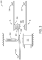
- the switching device may include a relay device 100 that is composed of components illustrated in FIG. 3 , some of which correspond to the components of the switching device described above.
- the relay device 100 may include an armature 102 that is coupled to a spring 104.
- the armature 102 may have a common contact 106 that may be coupled to a part of an electrical circuit.
- the armature 102 may electrically couple the common contact 106 to a contact 108 or to a contact 110 depending on a state ( e.g ., energized) of the relay device 100.
- the armature 102 is positioned such that the common contact 106 and the contact 108 are electrically coupled to each other.
- the relay coil 112 receives a driving voltage, the relay coil 112 magnetizes and attracts the armature 102 to itself, thereby connecting the contract 110 to the common contact 106.
- the electrical connections between the common contact 106 and the contacts 108 and 110 are made via contacts 114 and 116 and contacts 118 and 120, respectively. Over time, as the contacts 114 and 116 and the contacts 118 and 120 strike against each other, the conductive material of the contacts 114, 116, 118, and 120 may begin to wear.
- the relay coil 112 may include a core that minimizes a core flux during the operation of the relay device 100. That is, as the armature 102 moves between connecting to the contact 108 and the contact 110, and vice-versa, a magnetic flux may be generated in a core of the relay coil 112 and/or the armature 102. This magnetic flux may be related to the core flux of the relay coil 112 and may change over time as the relay device operates.
- the switchgear 16 may control operation of a load 14 (e.g ., electric motor 24) by controlling electric power supplied to the load 14.
- a load 14 e.g ., electric motor 24
- switching devices e.g ., contacts
- opening (e.g ., breaking) and closing (e.g ., making) the switching devices may discharge electric power in the form of electric arcing, thereby causing current oscillations to be supplied to the load 14, and/or cause the load 14 to produce torque oscillations
- embodiments of the present disclosure provide techniques for opening a switching device in coordination with a specific point on an electric power waveform
- the switching device may open based on a predicted current zero-crossing of a multi-phase signal conducting through the respective switching device.
- a "current zero-crossing" is intended to describe when the current conducted by the switching device is zero. Accordingly, by opening before or at a current zero-crossing, the time of arcing is minimal since the conducted current is zero
- the switching devices may be controlled to open and close at any desired point on the waveform using the disclosed techniques.
- one or more switching devices may be independently controlled to selectively connect and disconnect a phase of electric power to the load 14.
- the one or more switching devices may be a multi-pole, multi-current carrying path switching device that controls connection of each phase with a separate pole. More specifically, the multi-pole, multi-current carrying path switching device may control each phase of electric power by movement of a common assembly under the influence of a single operation (e.g. , an electromagnetic operator).
- each pole may be connected to the common assembly in an offset manner, thereby enabling movement of the common assembly to affect one or more of the poles differently.
- the one or more switching devices may include multiple single pole switching devices.
- a "single pole switching device" is intended to differentiate from a multi-pole, multi-current-carrying path switching device in that each phase is controlled by movement of a separate assembly under influence of a separate operator.
- the single pole switching device may be a single pole, multi-current carrying path switching device ( e.g ., multiple current carrying paths controlled by movement of a single operator) or a single-pole, single current-carrying path switching device, as described herein.
- controlling the opening of the one or more switching devices may facilitate reducing the magnitude of in-rush current and/or current oscillations, which may strain the load 14, the power source 12, and/or other connected components.
- the one or more switching devices may be controlled such that the switching devices open based at least in part on a predicted current zero-crossing ( e.g ., within a range slightly before to slightly after the predicted current zero crossing).
- a power factor associated with the electric motor may change based on the quantity of load current. For example, the timing of the POW switching along the electric power waveform may deviate when a steady state of the load current is not present.
- FIG. 4 illustrates a current-time graph 200 associated with one or more switching devices that may independently control connection of each phase with a separate pole.
- the current-time graph 200 depicts how the current through contacts of the one or more switching devices changes over time during a start-up sequence of an electric motor 24 (e.g., during a first time period 202), when a load is applied to the electric motor 24 (e.g., during a second time period 204), and when a load is decreased on the electric motor 24 (e.g., during a third period 206).
- each current zero-crossing point of each phase of the electric wave form may deviate from corresponding current zero-crossing points of each phase during a steady state of the load current.
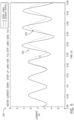
- FIG. 5 illustrates a current-time graph 210 that depicts how the current within through contacts of one or more switching devices changes over time when a load is applied to an electric motor 24 (e.g., line 212) as compared to a steady state of the load current (e.g., line 214).
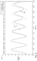
- FIG. 6 illustrates a current-time graph 220 that depicts how the current through contacts of one or more switching devices changes over time when a load is decreased from an electric motor 24 (e.g., line 222) as compared to a steady state of the load current (e.g., line 214).
- the timing of the current zero-crossing along the multi-phase signal when a load is applied to the electric motor 24 or a load is decreased from the electric motor 24 deviates from the timing of the current zero crossing along the multi-phase signal when the load current is experiencing a steady state.
- the timing of the current zero-crossing of the multi-phase signal may shift to lag (e.g., the rate of the current zero-crossing may increase) the timing of the current zero-crossing of the multi-phase signal during steady state of the load current.
- the timing of the current zero-crossing of the multi-phase signal may shift to lead (e.g., the rate of the current zero-crossing may decrease) the timing of the current zero-crossing of the multi-phase signal during steady state of the load current.
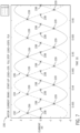
- FIG. 8 illustrates a current-time graph 230 that depicts how the current of a first phase (e.g., line 232) associated with a first contact of a switching device, a second phase (e.g., line 234) associated with a second contact of the switching device, and a third phase (e.g., line 236) associated with a third contact of the switching device changes over time.
- a first phase e.g., line 232
- a second phase e.g., line 234
- a third phase e.g., line 236
- FIG. 7 depicts a number of data points (e.g., data points 238) indicative of respective current zero-crossings along the first phase, the second phase, and the third phase of the multi-phase signal and a number of points (e.g., data points 239) indicative of respective crossings between two phases of the multi-phase signal (e.g., a current line-to-line crossing).
- a timing of a respective current zero-crossing along the multi-phase signal (e.g., a predicted current zero-crossing) may be predicted.
- FIG. 8 is a flowchart of a process 300 for predicting the timing of a current zero-crossing associated with a particular phase of a multi-phase signal based on historical current zero-crossing data and/or current line-to-line crossing data.
- the timing of the precited current zero-crossing may be employed to open a switching device (e.g., one or more contacts of the switching device) to minimize the magnitude and/or duration of arcing when opening the switching device.
- a switching device e.g., one or more contacts of the switching device
- the process 300 may be performed by any suitable control system or computing device.
- the process 300 is described in a particular order, it should be noted that the process 300 may be performed in any suitable order.
- the control and monitoring circuitry 18 may continuously determine and store respective period measurements from each detected current zero-crossing point and/or each detected current line-to-line crossing point based on a multi-phase waveform associated with a respective switching device.
- sensors 22 may continuously monitor characteristics (e.g., voltage or current) of the electric power input into the switching device.
- the control and monitoring circuitry 18 may receive sensor data from the sensors 22 associated with the monitored characteristics and continuously generate or update an electric waveform (e.g., a current waveform or a multi-phase signal) associated with the switching device based on the received sensor data.
- the electric waveform may include one or more data points indicative of respective current zero-crossings associated with a first phase, a second phase, or a third phase of the multi-phase signal or one or more data points indicative of respective current line-to-line crossings between phases of the multi-phase signal.
- the control and monitoring circuitry 18 may continuously determine and store a respective period measurement associated with each current zero-crossing data point and each current line-to-line crossing data point.
- the period measurement of a respective current zero-crossing data point may be equal to the time between the respective current zero-crossing data point and a previous current zero-crossing data point at a similar point along a particular phase signal.
- control and monitoring circuitry 302 may continuously determine and store respective period measurements for each current zero-crossing data point and/or each current line-to-line crossing data point as the process 300 is performed.
- control and monitoring circuitry 18 may filter one or more period measurements to remove noise after determining the period measurements.
- the control and monitoring circuitry 18 may receive a command to open the switching device. After the control and monitoring circuitry 18 receives the command to open or break the switching device, the control and monitoring circuitry 18 may select a current zero-crossing point as a synchronization point to determine an expected time of a predicted current zero-crossing point to open or break the switching device at block 306. For example, as illustrated in FIG. 9 , the control and monitoring circuity 18 may select the current zero-crossing point 352 as the synchronization point for a respective phase (e.g., the first phase 354).
- a respective phase e.g., the first phase 354
- the process 300 is described with respect to current zero-crossing point 352 being selected as the synchronization point, it should be understood that the synchronization point may be any suitable current zero-crossing point along the multi-phase signal after receiving the command to open or break the switching device.
- the control and monitoring circuity 18 may determine an expected timing of a predcited current zero-crossing point at block 308.
- the control and monitoring circuitry 18 may add a period measurement associated with the most recent current zero-crossing point or the most recent current line-to-line crossing point to the synchronization point to determine the expected timing of the predicted current zero-crossing point.
- the predicted current zero-crossing point may indicate the timing at which to open or break the switching device to minimize a magnitude and/or duration of arcing when opening or breaking the switching device. For example, as illustrated in FIG.
- current line-to-line crossing data point 354 is the most recent current line-to-line crossing data point before the selected synchronization data point 352.
- the control and monitoring circuitry 18 may retrieve the period measurement associated with the current line-to-line crossing data point 354 and add the period measurement to the synchronization point 352 to determine the expected timing of the predicted current zero-crossing (e.g., at data point 358). For instance, an expected period 356 between the synchronization point 352 and the expected timing of the predicted current zero-crossing at data point 358 is equivelent to the period measurement associated with the current line-to-line crossing data point 354.
- control and monitoring circuitry 18 may update the expected timing of the predicted current zero-crossing based on the additional period measurements at block 308. For example, after the control and monitoring circuitry 18 determines the period measurement 366 associated with the current line-to-line crossing point 362, the control and monitoring circuitry 18 updates the expected timing of the predicted current zero-crossing by adding the period measurement 366 to the synchronization point 352.
- control and monitoring circuitry 18 determines the period measurement 364 associated with the current zero-crossing point 360
- the control and monitoring circuitry 18 updates the expected timing of the predicted current zero-crossing by adding the period measurement 364 to the synchronization point 352. In this way, the control and monitoring circuitry 18 may continue to update the expected timing of the predicted current zero-crossing based on the period measurements associated with each current zero-crossing point and each current line-to-line crossing point until the predicted current zero-crossing point is reached. For example, as illustrated in FIG.
- block 310 may be performed by the control and monitoring circuitry 18 for each current zero-crossing point (e g., data point 360) and/or each current line-to-line crossing point (e.g., data point 362) until the predicted current zero-crossing is reached.
- the expected period measurement 356 may be optimized or adjusted based on one or more previously determined period measurements (e.g., period measurements 364 and 366) associated with current zero-crossing data points and/or current line-to-line data points to adjust the timing of the predicted current zero-crossing 358 for a respective phase along the multi-phase signal.
- the control and monitoring circuitry 18 may send a command to the switching device to open (e.g., the contact that corresponds to a first phase associated with the switching device).
- the control and monitoring circuitry 18 may send the command to the switching device at a suitable time before the timing of the predicted current zero-crossing 358 to account for a possible delay between sending the command to the switching device to open and a time at which the contacts associated with the switching device open.
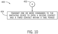
- FIG. 10 is a flowchart of a process 400 for opening a second contact associated with a second phase of the multi-phase signal and a third contact associated with a third phase of the multi-phase signal after the first contact has been opened.
- the process 400 will be described as being performed by the control and monitoring circuitry 18, it should be understood that the process 400 may be performed by any suitable control system or computing device.
- the process 400 is described in a particular order, it should be noted that the process 400 may be performed in any suitable order.
- the control and monitoring circuitry 18 may determine an expected timing of a predicted current zero-crossing associated with a first phase of the multi-phase signal at which to open or break a first contact of a switching device and send a command to the switching device to open the first contact before or at the predicted current zero-crossing at block 402. After the switching device opens before or at the predicted current zero-crossing, at block 404, the control and monitoring circuitry 18 may transmit one or more commands to the switching device to open the second contact associated with the second phase and the third contact associated with the third phase with a particular time period. In some embodiments, the time period may correspond to less than or equal to ninety degrees along the multi-phase signal from the predicted current zero-crossing, less than or equal to eighty degrees along the multi-phase signal from the predicted current zero-crossing, or the like.
- the first contact associated with the first phase may open after the current zero-crossing along the multi-phase signal, thereby causing some arcing. For example, if the first contact opens before or at the current zero-crossing, the current detected through the contact may stop after a period of time. However, if the control and monitoring circuitry 18 determines that the current detected through the first contact has reversed, the control and monitoring circuitry 18 may determine that the first contact has not opened or that the first contact has opened after the current zero-crossing.
- the contacts associated with the second phase and/or the third phase may also open after the respective current zero-crossing points along the multi-phase signal, thereby causing further arcing. Accordingly, in embodiments, if the control and monitoring circuitry 18 determines that a reversal of current through the first contact is present after the first contact has opened, the control and monitoring circuit 18 adjusts the respective timings for opening the contacts associated with the second phase and/or third phase to minimize the magnitude and/or duration of further arcing.
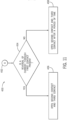
- FIG. 11 is a flowchart of a process 450 for determining whether a reversal of current is present after the first contact associated with the first phase has opened and determining a corresponding time to open the second contact associated with the second phase and the third contact associated with the third phase to minimize the magnitude and/or the duration of arcing when opening the second contact and the third contact.
- the process 450 will be described as being performed by the control and monitoring circuitry 18, it should be understood that the process 450 may be performed by any suitable control system or computing device.
- the process 450 is described in a particular order, it should be noted that the process 450 may be performed in any suitable order.
- the control and monitoring circuitry 18 may determine a timing of a predicted current zero-crossing associated with a first phase of the multi-phase signal at which to break a first contact of a switching device and send a command to the switching device to open or break the first contact before or at the predicted current zero-crossing at block 452. After the first contact of the switching device has opened, the control and monitoring circuitry 18 determines whether a reversal in the current through the first contact is present at block 454. For example, the control and monitoring circuitry 18 may receive voltage or current data from the sensors 22 associated with the switching device during a period of time after the first contact of the switching device has opened.
- control and monitoring circuitry 18 determines that a reversal of current through the first contact is present (e.g., the current is indicative of the first contact remaining closed) at block 454, the control and monitoring circuitry 18 sends a command to the switching device to open the second contact and the third contact immediately (e.g., after a first period of time) at block 456. In this way, the control and monitoring circuitry 18 opens the second contact and the third contact before the next respective current zero-crossings associated with the second phase and the third phase, thereby minimizing the magnitude and/or duration of arcing.
- the control and monitoring circuitry 18 may send a command to the switching device to open the second contact and the third contact after a second period of time has expired.
- the second period of time may be equal to a portion of the most recent period measurement associated with a current zero-crossing of the multi-phase signal or a current line-to-line crossing of the multi-phase signal divided.
- the second period of time may be any suitable period of time and may be application specific. Additionally, the second period of time may be greater than the first period of time.
- the process 450 may be performed instead of process 400 to open the second contact and the third contact.
- the control and monitoring circuitry 18 may determine that the first contact has not opened or that the first contact has opened after the current zero-crossing, thereby causing some arcing.
- the control and monitoring circuitry 18 may perform the process 450 to adjust the respective timings for opening the second contact and the third contact
Landscapes
- Physics & Mathematics (AREA)
- Electromagnetism (AREA)
- Engineering & Computer Science (AREA)
- Power Engineering (AREA)
- Keying Circuit Devices (AREA)
Claims (9)
- Ein System, das Folgendes umfasst:
eine Schaltvorrichtung (100), umfassend:einen oder mehrere Anker (102), die so konfiguriert sind, dass sie sich zwischen einer ersten Position, die einen ersten Kontakt (104) mit einem zweiten Kontakt (116) elektrisch koppelt, und einer zweiten Position, die den ersten Kontakt von dem zweiten Kontakt elektrisch entkoppelt, bewegen, wobei der eine oder die mehreren Anker einer ersten Phase einer elektrischen Wellenform zugeordnet sind, und wobei ein zweiter Anker, der der Schaltvorrichtung zugeordnet ist, einer zweiten Phase der elektrischen Wellenform zugeordnet ist und ein dritter Anker, der der Schaltvorrichtung zugeordnet ist, einer dritten Phase der elektrischen Wellenform zugeordnet ist; undeine Relaisspule (112), die so konfiguriert ist, dass sie eine Spannung empfängt, die so konfiguriert ist, dass sie die Relaisspule magnetisiert, wodurch der eine oder die mehreren Anker veranlasst werden, sich von der ersten Position zu der zweiten Position zu bewegen; undein Steuersystem (18), das so konfiguriert ist, dass es Vorgänge ausführt, die Folgendes umfassen:Empfangen eines Befehls zum Bewegen des einen oder der mehreren Anker von der ersten Position in die zweite Position;Auswählen eines Strom-Nulldurchgangspunkts entlang der elektrischen Wellenform als Synchronisationspunkt, wobei die elektrische Wellenform eine Änderung des Stroms durch den ersten Kontakt und den zweiten Kontakt anzeigt;Bestimmen eines vorhergesagten Strom-Nulldurchgangspunktes durch Addieren einer Periodenmessung, die mit einem zuvor erfassten Strom-Nulldurchgangspunkt oder einem zuvor erfassten Strom-Linie-zu-Linie-Durchgangspunkt in der elektrischen Wellenform verbunden ist, zu dem Synchronisationspunkt;Übertragen eines Befehls an die Schaltvorrichtung, um den einen oder die mehreren Anker von der ersten Position in die zweite Position vor oder an dem vorhergesagten Stromnulldurchgangspunkt zu bewegen;Bestimmen, ob eine Umkehrung des Stroms durch den ersten Kontakt und den zweiten Kontakt, der mit der ersten Phase verbunden ist, vorhanden ist; undals Reaktion auf die Feststellung, dass eine Stromumkehr durch den ersten Kontakt und den zweiten Kontakt, die der ersten Phase zugeordnet sind, vorhanden ist, Übertragen eines Befehls an die Schaltvorrichtung, um den zweiten Anker, den dritten Anker oder beide innerhalb einer ersten Zeitspanne zu bewegen, um Kontakte, die der zweiten Phase bzw. der dritten Phase zugeordnet sind, vor den nächsten jeweiligen Stromnulldurchgängen, die der zweiten Phase und der dritten Phase zugeordnet sind, zu öffnen. - System nach Anspruch 1, wobei das Steuersystem so konfiguriert ist, dass es die Vorgänge durchführt, die das Anpassen des vorhergesagten Stromnulldurchgangs auf der Grundlage einer oder mehrerer zusätzlicher Periodenmessungen, die mit einem oder mehreren zusätzlichen Stromnulldurchgangspunkten nach dem Synchronisationspunkt verbunden sind, einem oder mehreren zusätzlichen Stromleitungsdurchgangspunkten nach dem Synchronisationspunkt oder beiden umfassen.
- System nach Anspruch 2, wobei der eine oder die mehreren zusätzlichen Strom-Nulldurchgangspunkte, der eine oder die mehreren zusätzlichen Strom-Linien-Durchgangspunkte oder beide jeden Strom-Nulldurchgangspunkt zwischen dem Synchronisationspunkt und dem vorhergesagten Strom-Nulldurchgangspunkt entlang der elektrischen Wellenform, jeden Strom-Linien-Durchgangspunkt zwischen dem Synchronisationspunkt und dem vorhergesagten Strom-Nulldurchgangspunkt entlang der elektrischen Wellenform oder beide umfassen.
- System nach einem der Ansprüche 1 bis 3, mit mindestens einem der folgenden Merkmale:
wobei das Steuersystem so konfiguriert ist, dass es die Operationen durchführt, die das Anpassen des vorhergesagten Stromnulldurchgangspunkts umfassen, indem es:Hinzufügen einer aktualisierten Periodenmessung, die mit einem zusätzlichen Strom-Nulldurchgangspunkt oder einem zusätzlichen Strom-Leitungs-Durchgangspunkt verbunden ist, zu dem Synchronisationspunkt;wobei der als Synchronisationspunkt ausgewählte Stromnulldurchgangspunkt ein nachfolgender Stromnulldurchgangspunkt entlang der elektrischen Wellenform ist, nachdem der Befehl zum Bewegen des Ankers empfangen wurde;wobei das Steuersystem so konfiguriert ist, dass es die Operationen durchführt, die das Empfangen von Sensordaten, die mit einer von der Schaltvorrichtung empfangenen elektrischen Leistung verbunden sind, und das Erzeugen der elektrischen Wellenform auf der Grundlage der Sensordaten umfassen; undwobei das Steuersystem so konfiguriert ist, dass es die Operationen durchführt, die das kontinuierliche Bestimmen einer Vielzahl von Periodenmessungen umfassen, die mit jedem Stromnulldurchgangspunkt und jedem Stromlinie-zu-Linie-Durchgangspunkt entlang der elektrischen Wellenform verbunden sind, wobei die Vielzahl von Periodenmessungen die Periodenmessung, die mit dem zuvor erfassten Stromnulldurchgangspunkt oder dem zuvor erfassten Stromlinie-zu-Linie-Durchgangspunkt verbunden ist, und die jeweiligen Periodenmessungen umfasst. - Ein nicht-transitorisches, computerlesbares Speichermedium, das Anweisungen enthält, die, wenn sie von einem oder mehreren Prozessoren ausgeführt werden, den einen oder die mehreren Prozessoren veranlassen, Operationen durchzuführen, die Folgendes umfassenEmpfangen eines Befehls zum Bewegen eines oder mehrerer Anker (102) einer Schaltvorrichtung (100) von einer ersten Position zu einer zweiten Position, wobei die erste Position des einen oder der mehreren Anker einen ersten Kontakt (114) mit einem zweiten Kontakt (116) elektrisch koppelt und die zweite Position des einen oder der mehreren Anker den ersten Kontakt von dem zweiten Kontakt elektrisch entkoppelt, wobei der eine oder die mehreren Anker einer ersten Phase einer elektrischen Wellenform zugeordnet sind, und wobei ein zweiter Anker, der der Schaltvorrichtung zugeordnet ist, einer zweiten Phase der elektrischen Wellenform zugeordnet ist und ein dritter Anker, der der Schaltvorrichtung zugeordnet ist, einer dritten Phase der elektrischen Wellenform zugeordnet ist;Auswählen eines Strom-Nulldurchgangspunkts entlang der elektrischen Wellenform als Synchronisationspunkt, wobei die elektrische Wellenform eine Änderung des Stroms durch den ersten Kontakt und den zweiten Kontakt anzeigt;Bestimmen eines vorhergesagten Stromnulldurchgangspunkts durch Addieren einer Periodenmessung, die mit einem zuvor erfassten Stromnulldurchgangspunkt oder einem zuvor erfassten Linie-zu-Linie-Durchgangspunkt in der elektrischen Wellenform verbunden ist, zu dem Synchronisationspunkt;Übertragen eines Befehls an die Schaltvorrichtung, um den einen oder die mehreren Anker von der ersten Position in die zweite Position vor oder bei dem vorhergesagten Stromnulldurchgangspunkt zu bewegen;Bestimmen, ob eine Umkehrung des Stroms durch den ersten Kontakt und den zweiten Kontakt, der mit der ersten Phase verbunden ist, vorhanden ist; undals Reaktion auf die Feststellung, dass eine Stromumkehr durch den ersten Kontakt und den zweiten Kontakt, die der ersten Phase zugeordnet sind, vorhanden ist, Übertragen eines Befehls an die Schaltvorrichtung, um den zweiten Anker, den dritten Anker oder beide innerhalb einer ersten Zeitspanne zu bewegen, um Kontakte, die der zweiten Phase bzw. der dritten Phase zugeordnet sind, vor den nächsten jeweiligen Stromnulldurchgängen, die der zweiten Phase und der dritten Phase zugeordnet sind, zu öffnen.
- Nicht-transitorisches, computerlesbares Speichermedium nach Anspruch 5, mit mindestens einem der folgenden Merkmale:
wobei die Operationen das Anpassen des vorhergesagten aktuellen Nulldurchgangspunktes umfassen durch:Hinzufügen einer aktualisierten Periodenmessung, die mit einem zusätzlichen Strom-Nulldurchgangspunkt oder einem zusätzlichen Strom-Leitungs-Durchgangspunkt verbunden ist, zu dem Synchronisationspunkt; undwobei das Übertragen des Befehls an die Schaltvorrichtung, um den einen oder die mehreren Anker von der ersten Position zu der zweiten Position vor oder zu dem vorhergesagten Stromnulldurchgangspunkt zu bewegen, das Übertragen des Befehls zu einem Zeitpunkt vor dem vorhergesagten Stromnulldurchgangspunkt basierend auf einer Verzögerung zwischen dem Übertragen des Befehls an die Schaltvorrichtung und dem Bewegen des einen oder der mehreren Anker von der ersten Position zu der zweiten Position umfasst. - Nicht-transitorisches, computerlesbares Speichermedium nach Anspruch 5 oder 6, wobei die Vorgänge das Übertragen eines Befehls an die Schaltvorrichtung umfassen, um den zweiten Anker, den dritten Anker oder beide innerhalb einer zweiten Zeitspanne in Reaktion auf die Feststellung zu bewegen, dass die Umkehrung des Stroms durch den ersten Kontakt und den zweiten Kontakt, die mit der ersten Phase zum Öffnen verbunden ist, nicht vorhanden ist.
- Nicht-übertragbares, computerlesbares Speichermedium nach Anspruch 7, wobei die zweite Zeitspanne größer ist als die erste Zeitspanne.
- Ein Verfahren, das Folgendes umfasst:Empfangen (304) eines Befehls zum Bewegen eines oder mehrerer Anker (102) einer Schaltvorrichtung (100) von einer ersten Position zu einer zweiten Position über einen oder mehrere Prozessoren, wobei die erste Position des einen oder der mehreren Anker einen ersten Kontakt (114) mit einem zweiten Kontakt (116) elektrisch koppelt und die zweite Position des einen oder der mehreren Anker den ersten Kontakt von dem zweiten Kontakt elektrisch entkoppelt, wobei der eine oder die mehreren Anker einer ersten Phase einer elektrischen Wellenform zugeordnet sind, und wobei ein zweiter Anker, der der Schaltvorrichtung zugeordnet ist, einer zweiten Phase der elektrischen Wellenform zugeordnet ist und ein dritter Anker, der der Schaltvorrichtung zugeordnet ist, einer dritten Phase der elektrischen Wellenform zugeordnet ist;Auswählen (306), über den einen oder die mehreren Prozessoren, eines Strom-Nulldurchgangspunkts entlang der elektrischen Wellenform als Synchronisationspunkt, wobei die elektrische Wellenform eine Änderung des Stroms durch den ersten Kontakt und den zweiten Kontakt anzeigt;Bestimmen (308), über den einen oder die mehreren Prozessoren, eines vorhergesagten Strom-nulldurchgangspunktes durch Addieren einer Periodenmessung, die mit einem zuvor erfassten Stromnulldurchgangspunkt oder einem zuvor erfassten Linie-zu-Linie-Durchgangspunkt in der elektrischen Wellenform verbunden ist, zu dem SynchronisationspunktÜbertragen (312) eines Befehls über den einen oder die mehreren Prozessoren an die Schaltvorrichtung, um den einen oder die mehreren Anker von der ersten Position in die zweite Position vor oder bei dem vorhergesagten Stromnulldurchgangspunkt zu bewegen;Bestimmen (454), ob eine Umkehrung des Stroms durch den ersten Kontakt und den zweiten Kontakt, der mit der ersten Phase verbunden ist, vorhanden ist; undals Reaktion auf die Feststellung, dass eine Stromumkehr durch den ersten Kontakt und den zweiten Kontakt, die der ersten Phase zugeordnet sind, vorliegt, Übertragen (456) eines Befehls an die Schaltvorrichtung, den zweiten Anker, den dritten Anker oder beide innerhalb einer ersten Zeitspanne zu bewegen, um Kontakte, die der zweiten Phase bzw. der dritten Phase zugeordnet sind, vor den nächsten jeweiligen Stromnulldurchgängen, die der zweiten Phase und der dritten Phase zugeordnet sind, zu öffnen.
Applications Claiming Priority (1)
| Application Number | Priority Date | Filing Date | Title |
|---|---|---|---|
| US17/485,748 US11830693B2 (en) | 2021-09-27 | 2021-09-27 | Predicting zero-crossings for point-on-wave (POW) switching techniques |
Publications (2)
| Publication Number | Publication Date |
|---|---|
| EP4156218A1 EP4156218A1 (de) | 2023-03-29 |
| EP4156218B1 true EP4156218B1 (de) | 2024-08-28 |
Family
ID=83506097
Family Applications (1)
| Application Number | Title | Priority Date | Filing Date |
|---|---|---|---|
| EP22198004.8A Active EP4156218B1 (de) | 2021-09-27 | 2022-09-27 | Vorhersage von nulldurchgangs für paw-schalttechniken |
Country Status (2)
| Country | Link |
|---|---|
| US (1) | US11830693B2 (de) |
| EP (1) | EP4156218B1 (de) |
Families Citing this family (1)
| Publication number | Priority date | Publication date | Assignee | Title |
|---|---|---|---|---|
| US20240322551A1 (en) * | 2023-03-21 | 2024-09-26 | Saudi Arabian Oil Company | Circuit breaker protection from delayed zero-crossing |
Family Cites Families (10)
| Publication number | Priority date | Publication date | Assignee | Title |
|---|---|---|---|---|
| DE4219834A1 (de) | 1992-06-17 | 1993-12-23 | Fraunhofer Ges Forschung | Verfahren und Vorrichtung zur Ansteuerung eines elektromagnetischen Schalters |
| JP2000188044A (ja) | 1998-12-21 | 2000-07-04 | Mitsubishi Electric Corp | 位相制御開閉装置 |
| US6768615B2 (en) | 2002-06-24 | 2004-07-27 | Daniel Liu | Spark elimination circuit for controlling relay contacts |
| US20040169987A1 (en) * | 2003-02-28 | 2004-09-02 | Robert Green | Electronic relay controller |
| JP5355187B2 (ja) | 2009-04-03 | 2013-11-27 | 株式会社東芝 | 遮断器の開閉制御システム |
| US8373313B2 (en) * | 2009-06-15 | 2013-02-12 | Homerun Holdings Corporation | Three-way switch for home automation apparatus and method |
| JP5660236B1 (ja) | 2014-02-27 | 2015-01-28 | オムロン株式会社 | 電磁継電器の異常検出方法、電磁継電器の異常検出回路、及び、異常検出システム |
| US9772381B2 (en) | 2014-11-06 | 2017-09-26 | Rockwell Automation Technologies, Inc. | Synchronized reapplication of power for driving an electric motor |
| US10396688B2 (en) * | 2017-08-04 | 2019-08-27 | Rockwell Automation Technologies, Inc. | PCB motor controller with POW switching |
| CN110729155A (zh) | 2018-07-17 | 2020-01-24 | 国网江苏省电力有限公司常州供电分公司 | 一种自学习控制合闸相位的方法 |
-
2021
- 2021-09-27 US US17/485,748 patent/US11830693B2/en active Active
-
2022
- 2022-09-27 EP EP22198004.8A patent/EP4156218B1/de active Active
Also Published As
| Publication number | Publication date |
|---|---|
| US20230102770A1 (en) | 2023-03-30 |
| EP4156218A1 (de) | 2023-03-29 |
| US11830693B2 (en) | 2023-11-28 |
Similar Documents
| Publication | Publication Date | Title |
|---|---|---|
| US10866284B2 (en) | Temperature-based electromagnetic switching | |
| US10074497B2 (en) | Operator coil parameter based electromagnetic switching | |
| US10141143B2 (en) | Wear-balanced electromagnetic motor control switching | |
| US9806641B2 (en) | Detection of electric motor short circuits | |
| US10361051B2 (en) | Single pole, single current path switching system and method | |
| US9806642B2 (en) | Modular multiple single-pole electromagnetic switching system and method | |
| US9722513B2 (en) | Torque-based stepwise motor starting | |
| US12347636B2 (en) | Systems and methods for detecting welded contacts in a switch system | |
| EP3799098A1 (de) | Relaisspulenantriebsschaltung | |
| US11651918B2 (en) | Sensing properties of switching devices using back EMF measurements | |
| US9748873B2 (en) | 5-pole based wye-delta motor starting system and method | |
| EP4156221B1 (de) | Systeme und verfahren zur erkennung geschweisster kontakte in einem elektromagnetischen schaltsystem | |
| EP4156218B1 (de) | Vorhersage von nulldurchgangs für paw-schalttechniken | |
| EP4160643A2 (de) | Systeme und verfahren zur normalisierung von energie mit offenem lichtbogen |
Legal Events
| Date | Code | Title | Description |
|---|---|---|---|
| PUAI | Public reference made under article 153(3) epc to a published international application that has entered the european phase |
Free format text: ORIGINAL CODE: 0009012 |
|
| STAA | Information on the status of an ep patent application or granted ep patent |
Free format text: STATUS: THE APPLICATION HAS BEEN PUBLISHED |
|
| AK | Designated contracting states |
Kind code of ref document: A1 Designated state(s): AL AT BE BG CH CY CZ DE DK EE ES FI FR GB GR HR HU IE IS IT LI LT LU LV MC MK MT NL NO PL PT RO RS SE SI SK SM TR |
|
| STAA | Information on the status of an ep patent application or granted ep patent |
Free format text: STATUS: REQUEST FOR EXAMINATION WAS MADE |
|
| 17P | Request for examination filed |
Effective date: 20230914 |
|
| RBV | Designated contracting states (corrected) |
Designated state(s): AL AT BE BG CH CY CZ DE DK EE ES FI FR GB GR HR HU IE IS IT LI LT LU LV MC MK MT NL NO PL PT RO RS SE SI SK SM TR |
|
| GRAP | Despatch of communication of intention to grant a patent |
Free format text: ORIGINAL CODE: EPIDOSNIGR1 |
|
| STAA | Information on the status of an ep patent application or granted ep patent |
Free format text: STATUS: GRANT OF PATENT IS INTENDED |
|
| INTG | Intention to grant announced |
Effective date: 20240416 |
|
| GRAS | Grant fee paid |
Free format text: ORIGINAL CODE: EPIDOSNIGR3 |
|
| GRAA | (expected) grant |
Free format text: ORIGINAL CODE: 0009210 |
|
| STAA | Information on the status of an ep patent application or granted ep patent |
Free format text: STATUS: THE PATENT HAS BEEN GRANTED |
|
| AK | Designated contracting states |
Kind code of ref document: B1 Designated state(s): AL AT BE BG CH CY CZ DE DK EE ES FI FR GB GR HR HU IE IS IT LI LT LU LV MC MK MT NL NO PL PT RO RS SE SI SK SM TR |
|
| REG | Reference to a national code |
Ref country code: CH Ref legal event code: EP |
|
| REG | Reference to a national code |
Ref country code: DE Ref legal event code: R096 Ref document number: 602022005659 Country of ref document: DE |
|
| REG | Reference to a national code |
Ref country code: IE Ref legal event code: FG4D |
|
| REG | Reference to a national code |
Ref country code: LT Ref legal event code: MG9D |
|
| PG25 | Lapsed in a contracting state [announced via postgrant information from national office to epo] |
Ref country code: NO Free format text: LAPSE BECAUSE OF FAILURE TO SUBMIT A TRANSLATION OF THE DESCRIPTION OR TO PAY THE FEE WITHIN THE PRESCRIBED TIME-LIMIT Effective date: 20241128 |
|
| REG | Reference to a national code |
Ref country code: AT Ref legal event code: MK05 Ref document number: 1718942 Country of ref document: AT Kind code of ref document: T Effective date: 20240828 |
|
| PG25 | Lapsed in a contracting state [announced via postgrant information from national office to epo] |
Ref country code: NL Free format text: LAPSE BECAUSE OF FAILURE TO SUBMIT A TRANSLATION OF THE DESCRIPTION OR TO PAY THE FEE WITHIN THE PRESCRIBED TIME-LIMIT Effective date: 20240828 Ref country code: GR Free format text: LAPSE BECAUSE OF FAILURE TO SUBMIT A TRANSLATION OF THE DESCRIPTION OR TO PAY THE FEE WITHIN THE PRESCRIBED TIME-LIMIT Effective date: 20241129 Ref country code: PT Free format text: LAPSE BECAUSE OF FAILURE TO SUBMIT A TRANSLATION OF THE DESCRIPTION OR TO PAY THE FEE WITHIN THE PRESCRIBED TIME-LIMIT Effective date: 20241230 Ref country code: FI Free format text: LAPSE BECAUSE OF FAILURE TO SUBMIT A TRANSLATION OF THE DESCRIPTION OR TO PAY THE FEE WITHIN THE PRESCRIBED TIME-LIMIT Effective date: 20240828 Ref country code: PL Free format text: LAPSE BECAUSE OF FAILURE TO SUBMIT A TRANSLATION OF THE DESCRIPTION OR TO PAY THE FEE WITHIN THE PRESCRIBED TIME-LIMIT Effective date: 20240828 |
|
| PG25 | Lapsed in a contracting state [announced via postgrant information from national office to epo] |
Ref country code: BG Free format text: LAPSE BECAUSE OF FAILURE TO SUBMIT A TRANSLATION OF THE DESCRIPTION OR TO PAY THE FEE WITHIN THE PRESCRIBED TIME-LIMIT Effective date: 20240828 |
|
| PG25 | Lapsed in a contracting state [announced via postgrant information from national office to epo] |
Ref country code: LV Free format text: LAPSE BECAUSE OF FAILURE TO SUBMIT A TRANSLATION OF THE DESCRIPTION OR TO PAY THE FEE WITHIN THE PRESCRIBED TIME-LIMIT Effective date: 20240828 |
|
| REG | Reference to a national code |
Ref country code: NL Ref legal event code: MP Effective date: 20240828 |
|
| PG25 | Lapsed in a contracting state [announced via postgrant information from national office to epo] |
Ref country code: IS Free format text: LAPSE BECAUSE OF FAILURE TO SUBMIT A TRANSLATION OF THE DESCRIPTION OR TO PAY THE FEE WITHIN THE PRESCRIBED TIME-LIMIT Effective date: 20241228 Ref country code: AT Free format text: LAPSE BECAUSE OF FAILURE TO SUBMIT A TRANSLATION OF THE DESCRIPTION OR TO PAY THE FEE WITHIN THE PRESCRIBED TIME-LIMIT Effective date: 20240828 |
|
| PG25 | Lapsed in a contracting state [announced via postgrant information from national office to epo] |
Ref country code: HR Free format text: LAPSE BECAUSE OF FAILURE TO SUBMIT A TRANSLATION OF THE DESCRIPTION OR TO PAY THE FEE WITHIN THE PRESCRIBED TIME-LIMIT Effective date: 20240828 |
|
| PG25 | Lapsed in a contracting state [announced via postgrant information from national office to epo] |
Ref country code: RS Free format text: LAPSE BECAUSE OF FAILURE TO SUBMIT A TRANSLATION OF THE DESCRIPTION OR TO PAY THE FEE WITHIN THE PRESCRIBED TIME-LIMIT Effective date: 20241128 Ref country code: ES Free format text: LAPSE BECAUSE OF FAILURE TO SUBMIT A TRANSLATION OF THE DESCRIPTION OR TO PAY THE FEE WITHIN THE PRESCRIBED TIME-LIMIT Effective date: 20240828 |
|
| PG25 | Lapsed in a contracting state [announced via postgrant information from national office to epo] |
Ref country code: RS Free format text: LAPSE BECAUSE OF FAILURE TO SUBMIT A TRANSLATION OF THE DESCRIPTION OR TO PAY THE FEE WITHIN THE PRESCRIBED TIME-LIMIT Effective date: 20241128 Ref country code: PT Free format text: LAPSE BECAUSE OF FAILURE TO SUBMIT A TRANSLATION OF THE DESCRIPTION OR TO PAY THE FEE WITHIN THE PRESCRIBED TIME-LIMIT Effective date: 20241230 Ref country code: PL Free format text: LAPSE BECAUSE OF FAILURE TO SUBMIT A TRANSLATION OF THE DESCRIPTION OR TO PAY THE FEE WITHIN THE PRESCRIBED TIME-LIMIT Effective date: 20240828 Ref country code: NO Free format text: LAPSE BECAUSE OF FAILURE TO SUBMIT A TRANSLATION OF THE DESCRIPTION OR TO PAY THE FEE WITHIN THE PRESCRIBED TIME-LIMIT Effective date: 20241128 Ref country code: NL Free format text: LAPSE BECAUSE OF FAILURE TO SUBMIT A TRANSLATION OF THE DESCRIPTION OR TO PAY THE FEE WITHIN THE PRESCRIBED TIME-LIMIT Effective date: 20240828 Ref country code: LV Free format text: LAPSE BECAUSE OF FAILURE TO SUBMIT A TRANSLATION OF THE DESCRIPTION OR TO PAY THE FEE WITHIN THE PRESCRIBED TIME-LIMIT Effective date: 20240828 Ref country code: IS Free format text: LAPSE BECAUSE OF FAILURE TO SUBMIT A TRANSLATION OF THE DESCRIPTION OR TO PAY THE FEE WITHIN THE PRESCRIBED TIME-LIMIT Effective date: 20241228 Ref country code: HR Free format text: LAPSE BECAUSE OF FAILURE TO SUBMIT A TRANSLATION OF THE DESCRIPTION OR TO PAY THE FEE WITHIN THE PRESCRIBED TIME-LIMIT Effective date: 20240828 Ref country code: GR Free format text: LAPSE BECAUSE OF FAILURE TO SUBMIT A TRANSLATION OF THE DESCRIPTION OR TO PAY THE FEE WITHIN THE PRESCRIBED TIME-LIMIT Effective date: 20241129 Ref country code: FI Free format text: LAPSE BECAUSE OF FAILURE TO SUBMIT A TRANSLATION OF THE DESCRIPTION OR TO PAY THE FEE WITHIN THE PRESCRIBED TIME-LIMIT Effective date: 20240828 Ref country code: ES Free format text: LAPSE BECAUSE OF FAILURE TO SUBMIT A TRANSLATION OF THE DESCRIPTION OR TO PAY THE FEE WITHIN THE PRESCRIBED TIME-LIMIT Effective date: 20240828 Ref country code: BG Free format text: LAPSE BECAUSE OF FAILURE TO SUBMIT A TRANSLATION OF THE DESCRIPTION OR TO PAY THE FEE WITHIN THE PRESCRIBED TIME-LIMIT Effective date: 20240828 Ref country code: AT Free format text: LAPSE BECAUSE OF FAILURE TO SUBMIT A TRANSLATION OF THE DESCRIPTION OR TO PAY THE FEE WITHIN THE PRESCRIBED TIME-LIMIT Effective date: 20240828 |
|
| PG25 | Lapsed in a contracting state [announced via postgrant information from national office to epo] |
Ref country code: SM Free format text: LAPSE BECAUSE OF FAILURE TO SUBMIT A TRANSLATION OF THE DESCRIPTION OR TO PAY THE FEE WITHIN THE PRESCRIBED TIME-LIMIT Effective date: 20240828 Ref country code: RO Free format text: LAPSE BECAUSE OF FAILURE TO SUBMIT A TRANSLATION OF THE DESCRIPTION OR TO PAY THE FEE WITHIN THE PRESCRIBED TIME-LIMIT Effective date: 20240828 Ref country code: DK Free format text: LAPSE BECAUSE OF FAILURE TO SUBMIT A TRANSLATION OF THE DESCRIPTION OR TO PAY THE FEE WITHIN THE PRESCRIBED TIME-LIMIT Effective date: 20240828 |
|
| PG25 | Lapsed in a contracting state [announced via postgrant information from national office to epo] |
Ref country code: EE Free format text: LAPSE BECAUSE OF FAILURE TO SUBMIT A TRANSLATION OF THE DESCRIPTION OR TO PAY THE FEE WITHIN THE PRESCRIBED TIME-LIMIT Effective date: 20240828 |
|
| PG25 | Lapsed in a contracting state [announced via postgrant information from national office to epo] |
Ref country code: CZ Free format text: LAPSE BECAUSE OF FAILURE TO SUBMIT A TRANSLATION OF THE DESCRIPTION OR TO PAY THE FEE WITHIN THE PRESCRIBED TIME-LIMIT Effective date: 20240828 |
|
| PG25 | Lapsed in a contracting state [announced via postgrant information from national office to epo] |
Ref country code: SK Free format text: LAPSE BECAUSE OF FAILURE TO SUBMIT A TRANSLATION OF THE DESCRIPTION OR TO PAY THE FEE WITHIN THE PRESCRIBED TIME-LIMIT Effective date: 20240828 Ref country code: IT Free format text: LAPSE BECAUSE OF FAILURE TO SUBMIT A TRANSLATION OF THE DESCRIPTION OR TO PAY THE FEE WITHIN THE PRESCRIBED TIME-LIMIT Effective date: 20240828 |
|
| PG25 | Lapsed in a contracting state [announced via postgrant information from national office to epo] |
Ref country code: LU Free format text: LAPSE BECAUSE OF NON-PAYMENT OF DUE FEES Effective date: 20240927 |
|
| REG | Reference to a national code |
Ref country code: DE Ref legal event code: R097 Ref document number: 602022005659 Country of ref document: DE |
|
| PLBE | No opposition filed within time limit |
Free format text: ORIGINAL CODE: 0009261 |
|
| STAA | Information on the status of an ep patent application or granted ep patent |
Free format text: STATUS: NO OPPOSITION FILED WITHIN TIME LIMIT |
|
| PG25 | Lapsed in a contracting state [announced via postgrant information from national office to epo] |
Ref country code: MC Free format text: LAPSE BECAUSE OF FAILURE TO SUBMIT A TRANSLATION OF THE DESCRIPTION OR TO PAY THE FEE WITHIN THE PRESCRIBED TIME-LIMIT Effective date: 20240828 |
|
| REG | Reference to a national code |
Ref country code: BE Ref legal event code: MM Effective date: 20240930 |
|
| PG25 | Lapsed in a contracting state [announced via postgrant information from national office to epo] |
Ref country code: BE Free format text: LAPSE BECAUSE OF NON-PAYMENT OF DUE FEES Effective date: 20240930 |
|
| PG25 | Lapsed in a contracting state [announced via postgrant information from national office to epo] |
Ref country code: IE Free format text: LAPSE BECAUSE OF NON-PAYMENT OF DUE FEES Effective date: 20240927 |
|
| 26N | No opposition filed |
Effective date: 20250530 |
|
| PG25 | Lapsed in a contracting state [announced via postgrant information from national office to epo] |
Ref country code: SE Free format text: LAPSE BECAUSE OF FAILURE TO SUBMIT A TRANSLATION OF THE DESCRIPTION OR TO PAY THE FEE WITHIN THE PRESCRIBED TIME-LIMIT Effective date: 20240828 |
|
| PGFP | Annual fee paid to national office [announced via postgrant information from national office to epo] |
Ref country code: DE Payment date: 20250820 Year of fee payment: 4 |
|
| PGFP | Annual fee paid to national office [announced via postgrant information from national office to epo] |
Ref country code: FR Payment date: 20250821 Year of fee payment: 4 |
|
| PG25 | Lapsed in a contracting state [announced via postgrant information from national office to epo] |
Ref country code: CY Free format text: LAPSE BECAUSE OF FAILURE TO SUBMIT A TRANSLATION OF THE DESCRIPTION OR TO PAY THE FEE WITHIN THE PRESCRIBED TIME-LIMIT; INVALID AB INITIO Effective date: 20220927 |
|
| PG25 | Lapsed in a contracting state [announced via postgrant information from national office to epo] |
Ref country code: HU Free format text: LAPSE BECAUSE OF FAILURE TO SUBMIT A TRANSLATION OF THE DESCRIPTION OR TO PAY THE FEE WITHIN THE PRESCRIBED TIME-LIMIT; INVALID AB INITIO Effective date: 20220927 |