EP2631996B1 - Vorrichtung zur Energieversorgung für eine Leuchtenanschlussklemme, sowie Leuchte - Google Patents
Vorrichtung zur Energieversorgung für eine Leuchtenanschlussklemme, sowie Leuchte Download PDFInfo
- Publication number
- EP2631996B1 EP2631996B1 EP13000894.9A EP13000894A EP2631996B1 EP 2631996 B1 EP2631996 B1 EP 2631996B1 EP 13000894 A EP13000894 A EP 13000894A EP 2631996 B1 EP2631996 B1 EP 2631996B1
- Authority
- EP
- European Patent Office
- Prior art keywords
- lamp
- housing
- connecting terminal
- connection terminal
- terminal
- Prior art date
- Legal status (The legal status is an assumption and is not a legal conclusion. Google has not performed a legal analysis and makes no representation as to the accuracy of the status listed.)
- Active
Links
Images


Classifications
-
- H—ELECTRICITY
- H01—ELECTRIC ELEMENTS
- H01R—ELECTRICALLY-CONDUCTIVE CONNECTIONS; STRUCTURAL ASSOCIATIONS OF A PLURALITY OF MUTUALLY-INSULATED ELECTRICAL CONNECTING ELEMENTS; COUPLING DEVICES; CURRENT COLLECTORS
- H01R13/00—Details of coupling devices of the kinds covered by groups H01R12/70 or H01R24/00 - H01R33/00
- H01R13/73—Means for mounting coupling parts to apparatus or structures, e.g. to a wall
- H01R13/74—Means for mounting coupling parts in openings of a panel
- H01R13/741—Means for mounting coupling parts in openings of a panel using snap fastening means
- H01R13/743—Means for mounting coupling parts in openings of a panel using snap fastening means integral with the housing
-
- H—ELECTRICITY
- H01—ELECTRIC ELEMENTS
- H01R—ELECTRICALLY-CONDUCTIVE CONNECTIONS; STRUCTURAL ASSOCIATIONS OF A PLURALITY OF MUTUALLY-INSULATED ELECTRICAL CONNECTING ELEMENTS; COUPLING DEVICES; CURRENT COLLECTORS
- H01R13/00—Details of coupling devices of the kinds covered by groups H01R12/70 or H01R24/00 - H01R33/00
- H01R13/46—Bases; Cases
- H01R13/50—Bases; Cases formed as an integral body
- H01R13/501—Bases; Cases formed as an integral body comprising an integral hinge or a frangible part
-
- H—ELECTRICITY
- H01—ELECTRIC ELEMENTS
- H01R—ELECTRICALLY-CONDUCTIVE CONNECTIONS; STRUCTURAL ASSOCIATIONS OF A PLURALITY OF MUTUALLY-INSULATED ELECTRICAL CONNECTING ELEMENTS; COUPLING DEVICES; CURRENT COLLECTORS
- H01R4/00—Electrically-conductive connections between two or more conductive members in direct contact, i.e. touching one another; Means for effecting or maintaining such contact; Electrically-conductive connections having two or more spaced connecting locations for conductors and using contact members penetrating insulation
- H01R4/28—Clamped connections, spring connections
- H01R4/48—Clamped connections, spring connections utilising a spring, clip, or other resilient member
- H01R4/4809—Clamped connections, spring connections utilising a spring, clip, or other resilient member using a leaf spring to bias the conductor toward the busbar
- H01R4/48185—Clamped connections, spring connections utilising a spring, clip, or other resilient member using a leaf spring to bias the conductor toward the busbar adapted for axial insertion of a wire end
- H01R4/4819—Clamped connections, spring connections utilising a spring, clip, or other resilient member using a leaf spring to bias the conductor toward the busbar adapted for axial insertion of a wire end the spring shape allowing insertion of the conductor end when the spring is unbiased
- H01R4/4821—Single-blade spring
-
- H—ELECTRICITY
- H01—ELECTRIC ELEMENTS
- H01R—ELECTRICALLY-CONDUCTIVE CONNECTIONS; STRUCTURAL ASSOCIATIONS OF A PLURALITY OF MUTUALLY-INSULATED ELECTRICAL CONNECTING ELEMENTS; COUPLING DEVICES; CURRENT COLLECTORS
- H01R4/00—Electrically-conductive connections between two or more conductive members in direct contact, i.e. touching one another; Means for effecting or maintaining such contact; Electrically-conductive connections having two or more spaced connecting locations for conductors and using contact members penetrating insulation
- H01R4/28—Clamped connections, spring connections
- H01R4/48—Clamped connections, spring connections utilising a spring, clip, or other resilient member
- H01R4/4809—Clamped connections, spring connections utilising a spring, clip, or other resilient member using a leaf spring to bias the conductor toward the busbar
- H01R4/4828—Spring-activating arrangements mounted on or integrally formed with the spring housing
- H01R4/483—Pivoting arrangements, e.g. lever pushing on the spring
-
- H—ELECTRICITY
- H01—ELECTRIC ELEMENTS
- H01R—ELECTRICALLY-CONDUCTIVE CONNECTIONS; STRUCTURAL ASSOCIATIONS OF A PLURALITY OF MUTUALLY-INSULATED ELECTRICAL CONNECTING ELEMENTS; COUPLING DEVICES; CURRENT COLLECTORS
- H01R4/00—Electrically-conductive connections between two or more conductive members in direct contact, i.e. touching one another; Means for effecting or maintaining such contact; Electrically-conductive connections having two or more spaced connecting locations for conductors and using contact members penetrating insulation
- H01R4/28—Clamped connections, spring connections
- H01R4/48—Clamped connections, spring connections utilising a spring, clip, or other resilient member
- H01R4/4809—Clamped connections, spring connections utilising a spring, clip, or other resilient member using a leaf spring to bias the conductor toward the busbar
- H01R4/4846—Busbar details
- H01R4/485—Single busbar common to multiple springs
-
- H—ELECTRICITY
- H01—ELECTRIC ELEMENTS
- H01R—ELECTRICALLY-CONDUCTIVE CONNECTIONS; STRUCTURAL ASSOCIATIONS OF A PLURALITY OF MUTUALLY-INSULATED ELECTRICAL CONNECTING ELEMENTS; COUPLING DEVICES; CURRENT COLLECTORS
- H01R9/00—Structural associations of a plurality of mutually-insulated electrical connecting elements, e.g. terminal strips or terminal blocks; Terminals or binding posts mounted upon a base or in a case; Bases therefor
- H01R9/22—Bases, e.g. strip, block, panel
- H01R9/24—Terminal blocks
- H01R9/2491—Terminal blocks structurally associated with plugs or sockets
Definitions
- the invention relates to a device for energy supply for a lamp connection terminal according to the preamble of claim 1, and a lamp.
- Luminaire connection terminals are generally known and are usually arranged on the inside of the luminaire.
- the power cable is fed from the outside of the lamp through an opening in the lamp housing into the inside of the lamp and connected to the lamp connection terminal.
- the assembly is complex because the luminaire is to be opened so that the electrical conductors can be plugged in or out of the luminaire connection terminal. For this purpose, if the electrical line is to be passed on to a further luminaire, it should in turn first be fed out of the luminaire.
- a lamp connection terminal is arranged entirely within a lamp housing.
- Individual clamping elements are present in the device, it being possible for conductors of an electrical line to be connected in the individual clamping elements.
- Plug pins enable electrical contacting between the individual clamping elements and the lamp connection terminal, the electrical contacting being automatically provided when the device is mechanically fixed on the lamp housing. This can be disadvantageous for security reasons.
- the invention has for its object to provide a device for power supply for a lamp connector of the types mentioned in such a way that the assembly or disassembly of the device and the connection of the electrical line with the lamp connector in the lamp is improved and simplified, taking the necessary safety precautions should remain guaranteed. Furthermore, the manufacture of the device is to be simplified.
- the device according to the invention for energy supply for a lamp connection terminal has at least one connection adapter and a connection terminal, the connection adapter and the connection terminal being able to be arranged essentially outside a lamp housing of a lamp, the lamp connection terminal being able to be arranged essentially inside the lamp housing of the lamp, the device is electrically contactable with the lamp connection terminal, at least one electrical conductor of an electrical line, preferably a mains line, being used the device is directly or indirectly electrically contacted with the lamp connection terminal.
- connection terminal of the device essentially corresponds to the type of terminal of the luminaire connecting terminal.
- connection terminal of the device it is essential for the device that at least the electrical connections or the electrical contact parts of the connection terminal of the device are essentially identical to the electrical connections or electrical contact parts of the lamp connection terminal.
- the electrical connections are also called connection poles here.
- the electrical contact parts are also called stamped parts.
- the electrical conductors of the electrical line can be connected outside the lamp.
- the mains cable can then be fed in outside the luminaire.
- the assembly and disassembly is simplified and less complex because the lamp does not have to be opened.
- the forwarding of the electrical line to another lamp is also simplified.
- the electrical line with at least one electrical conductor can be led directly from the connection adapter outside the lamp to the next lamp, preferably to a further connection adapter of another device.
- the connection adapter is used for the power supply and can also be used for looping through for another luminaire.
- connection terminals are essentially identical, the production of such a terminal can be optimized, can be produced in larger quantities and the automation for the production can also be increased.
- the assembly of both connection terminals can also be automated and can advantageously be carried out on the same assembly system.
- connection adapter has a connection adapter fixed part and a connection adapter sliding part, the design being such that the connection adapter sliding part can be displaced relative to the connection adapter fixed part.
- Luminaire connection terminal for the luminaire can also be provided in the device.
- connection terminal of the device it is not necessary for the invention that the mechanical fastening elements of the connection terminal of the device have to be provided identically to the mechanical fastening elements of the lamp connection terminal, since the connection terminal in the connection adapter can be attached differently than the fastening of the lamp connection terminal on the lamp housing, especially for reasons of space.
- connection terminals in the device and in the luminaire, can preferably be conventional or standard mains connection terminals.
- connection terminal designed as a lamp connection terminal is arranged in the connection adapter of the device, for example in a receptacle of the connection adapter.
- connection terminal can have at least one housing with an upper and a lower region.
- the lamp connection terminal can also have at least one housing with an upper and a lower area.
- the upper area of the housing of the connection terminal can be configured essentially identically to an upper area of the housing of the provided light connection terminal.
- the terminal structure within the upper area of the housing of the connection terminal can be configured essentially identically to the terminal structure within the upper area of the housing of the provided light connection terminal.
- the electrical conductors of the electrical line can be inserted and / or removed from the connection poles of the connection terminal of the device without tools.
- the electrical conductors of the electrical line can be connected by a specialist in connection poles of the connection terminal of the device.
- connection adapter with the connection terminal in the connection adapter significantly simplifies the handling, assembly and disassembly of the electrical line for a lamp, since the lamp is no longer to be opened.
- the electrical conductors of the power line can be connected as before. This can be done by a specialist, preferably an electrician.
- the electrical power line is provided with a plug and that the connection terminal of the device is accordingly equipped with the counterpart of the plug in order in turn to enable the electrical power line to be connected to the device.
- an interface preferably known per se, can be present on the luminaire housing, it being possible for the device and the luminaire connection terminal to be contacted via the interface.
- the interface can also be used to fasten the device and / or the lamp connection terminal.
- a universal die cut pattern can be provided in the luminaire housing.
- the device and the lamp connection terminal can be provided with a corresponding or matching interface and / or coding.
- various devices and luminaire connection terminals may be necessary; the coding can prevent incorrect installation.
- the light connection terminal can have a lower area on the housing, which is designed with its fastening elements to match the interface on the light housing, the fastening elements additionally having a defined coding.
- the lower area of the housing of the connection terminal can, for example, be designed to be flatter or to match the receptacle in the connection adapter, the lower area of the housing having fastening elements that have a smaller design than the fastening elements of the lamp connection terminal.
- fastening elements for the connection terminal are present on the connection adapter, and in this case only holding or guiding elements are provided on the connection terminal, the design of the lower region of the housing of the connection terminal also being smaller than the design of the lower area of the housing of the lamp connection terminal.
- a coding can be provided in the connection adapter, which should be compatible with the coding of the lower area of the housing of the lamp connection terminal.
- the coding in the connection adapter can be present, for example, on the connection adapter fixed part and / or in an additional interface, which can preferably have at least one slider and a holding cover.
- At least one contact element can be provided between the connection terminal of the device and the light connection terminal within the light for electrical contacting of the device with the light connection terminal.
- the contact element (s) can be designed as a fork contact.
- the contact element can be designed as a fork contact on both sides.
- the fork legs of the fork contacts can be designed to be resilient so that lateral contacting can occur.
- the contact element can also have a fork contact on one side and a resilient tab on the other side.
- One contact element per connection pole can preferably be provided.
- the contact element can, for example, be arranged on one side in the connection terminal of the device, preferably inserted.
- the other side of the contact element can penetrate through a recess in the connection adapter in the assembled state.
- the contact element When assembled and contacted, the contact element can penetrate the lower area of the housing of the lamp connection terminal and create the electrical contact within the lamp connection terminal.
- connection adapter is designed in two parts, with a connection adapter fixed part and a connection adapter sliding part.
- the advantage is that the electrical contact between the connection terminal of the device and the lamp connection terminal can be interrupted, even if the electrical conductors of the electrical line are connected in the connection terminal of the device. If the connection adapter is decoupled or if the connection adapter sliding part is not snapped into the connection adapter fixed part, but is still present on the luminaire housing, the contact elements are no longer contacted with the luminaire connection terminal, resulting in protection against accidental contact.
- the principle can be known per se.
- non-electrical contact elements for contacting the device with the lamp connection terminal are present within the lamp.
- These contact elements can serve, for example, as positioning or guidance between the two parts. They can be designed as separate parts or as part of the connection adapter and / or the lamp connection terminal within the lamp.
- the device or the connection adapter can preferably also be mechanically attached to the lamp housing.
- the connection adapter can be mounted on the luminaire housing without making electrical contact between the connection terminal of the device and the luminaire connection terminal within the luminaire housing.
- connection adapter can have, for example, holding elements and the light housing can have fastening holes, the holding elements of the connection adapter being held in the fastening holes of the light housing. Mechanical fixation and stabilization of the device on the lamp housing can thus be provided.
- connection point of the power line in the device should not be open in the operating state. This can preferably be achieved by providing the device with a cover. When installed, this cover lies over the connection terminal of the connection adapter and can also cover the electrical conductors of the mains cable.
- the cover can, for example, be pivotally attached to the connection adapter, preferably to the connection adapter sliding part of the connection adapter. It is also conceivable that this protective cover can be displaceable or even completely extendable.
- the type of attachment of the lid to the device can be done in a manner known per se, e.g. with holding elements.
- a strain relief device can be provided for the electrical line. It can be arranged in the device or on the lamp housing. Alternatively, at least a part of the strain relief device can be formed in one piece with the connection adapter of the device. Another part of the strain relief device can either be designed as a swivel arm and on an axis of rotation of the Connection adapter can be arranged or the further part of the strain relief device can be designed as a sliding part and screwed to the first part. It can also be a known strain relief device.
- the invention relates to a lamp with the device according to the invention for supplying energy for a lamp connection terminal.
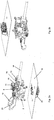
- FIG. 1a and Fig. 1b are perspective views of a device 1 according to the invention, which can be mounted on a schematically illustrated lamp housing 16.
- the device 1 is mounted outside the lamp.
- a lamp connection terminal 20 is fastened within the lamp or the lamp housing 16.
- FIG. 2a and Fig. 2b are perspective views of the device 1 shown, in contrast to Fig. 1a and 2 B the lid 12 of the device 1 is open.
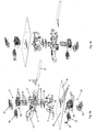
- the device 1 has a connection adapter 2, the connection adapter 2 consisting at least of a connection adapter fixed part 3 and a connection adapter sliding part 4.
- a receptacle 5 is provided in the connecting adapter sliding part 4, which can be used for the arrangement of a connecting terminal 8.
- connection terminal 8 can be a connection terminal known per se.
- Connection poles 11 are provided in the connection terminal 8 for the connection of electrical conductors 15 of an electrical line 14.
- the device 1 has a cover 12, which is pivotally arranged here on the connection adapter 2. In the closed state, this cover 12 serves as protection against contact.
- One or more holding elements 25 on the cover 12 enable the cover 12 to be fastened in or in the receptacles 26 on the connection adapter 2 so that the cover can be kept closed.
- a strain relief device 13 for the electrical line 14 is also provided here in this exemplary embodiment of the device 1. It is arranged on the connecting adapter sliding part 4.
- the device 1 can be mechanically attached to the lamp housing 16 via its holding elements 7.
- the holding elements 7 of the device 1 can be mounted in recesses 18 of the lamp housing 16. Holding hooks can be provided here, but also other holding means known per se.
- a lamp connector 20 is attached on the other side of the lamp housing 16, ie inside the lamp.
- 20 recesses are provided for fastening the luminaire connection terminal, which serve as interface 17 here.
- the lower region 22 of the housing 39 of the lamp connection terminal 20 has fastening elements 32 which can be fastened in the interface 17.
- Recesses 6 are provided below the device 1, on the connection adapter fixed part 3, which are adapted at the interface 17. In this embodiment, the cutouts 6 also serve as coding for the interface 17.
- connection adapter fixed part 3 and the connection adapter sliding part 4 preferably has at least one slide control 24 and a holding cover 29.
- connection terminal 8 of the device 1 and the lamp connection terminal 20 can be made by means of the electrical contact elements 19.
- the contact elements 19 are designed on the one hand as a resilient tab and are inserted in the connection terminal 8 through the cutouts 34 of the connection terminal 8. They are then in electrical contact with the stamped parts 28 of the connecting terminal 8.
- the electrical contact elements 19 are designed as fork contacts.
- the fork contacts penetrate through the connecting adapter sliding part 4, as well as through the interface and the connecting adapter fixed part 3.
- the holding cover 29 of the interface serves as an additional guide for the contact elements 19.
- the holding cover 29 always remains in the same position in comparison to the connecting adapter sliding part 4.
- the slider 24 serves as additional protection against contact for the contact elements 19. If the device 1 is not fully contacted with the lamp connection terminal 20, the slider 24 also blocks the contact elements 19 or the connector 8 from possible electrical contact with the lamp connection terminal 20.
- the slide controller 24 can have cutouts which can only be penetrated by the contact elements 19 in the contacted state. Otherwise are for example, the contact elements 19 are not in alignment with the cutouts of the slider 24.
- the electrical contact elements 19 When the device 1 is electrically contacted with the lamp connection terminal 20, the electrical contact elements 19 still penetrate through the interface 17 of the lamp housing 16 and through the recesses 35 of the lamp connection terminal 20, and are in contact with the electrical stamped parts of the lamp connection terminal 20.
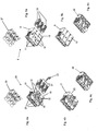
- connection terminal 20 4a, 4b and 4c
- connection terminal 8 of the device 1 5a, 5b, 5c
- the pushers 27 and 30 of both terminals 8 and 20 are identical.
- the stamped parts 28 and 31 of both terminals 8 and 20 are also identical.
- the upper regions 9 and 21 of both housings 38 and 39 of the terminals 8 and 20 are identical, so that the connection poles 11 and 23 of both terminals 8 and 20 are also identical.
- the light connection terminal 20 additionally has a grounding element 33.
- FIGS 6 to 9 The assembly of the device 1 on the luminaire housing 16 and its contacting with the luminaire connection terminal 20 is shown in FIGS 6 to 9 shown.
- the device 1 is first mechanically fastened in the sliding direction S1, here in the vertical direction, on the lamp housing 16, with its holding elements 7 being hooked into the fastening holes 18 in the lamp housing 16.
- the electrical contact elements 19 are located within the device 1 and do not come into contact with the electrical parts or the stamped parts 31 of the lamp connection terminal 20. Protection against accidental contact is available in this case.
- the slider 24 is still in a locked position for the contact elements 19.
- connection adapter fixed part 3 of the device 1 can be pushed in the sliding direction S2, here in the horizontal direction, so that the electrical contact elements 19 can be positioned in alignment with the recesses 35 of the lamp connection terminal 20.
- the slider 24 is thereby also released for the contact elements 19. At this assembly point, however, there is still no electrical contact between the connection terminal 8 of the device 1 and the lamp connection terminal 20.
- connection adapter sliding part 4 is shifted in the sliding direction S3, here in the vertical direction.
- the connecting terminal 8 and the electrical contact elements 19 are thus also displaced in the direction S3.
- the electrical contact elements 19 penetrate into the cutouts 35 in the lamp connection terminal 20 and enable electrical contact between the connection terminal 8 of the device 1 and the lamp connection terminal 20.
- the snap elements 36 of the connecting adapter sliding part 4 then snap onto retaining lugs 37 of the connecting adapter fixed part 3 in order to hold the connecting adapter sliding part 4 in position, as a security so that the electrical contacts cannot be unintentionally released by the contact elements 19.
Landscapes
- Arrangement Of Elements, Cooling, Sealing, Or The Like Of Lighting Devices (AREA)
- Fastening Of Light Sources Or Lamp Holders (AREA)
Description
- Die Erfindung betrifft eine Vorrichtung zur Energieversorgung für eine Leuchtenanschlussklemme nach dem Oberbegriff des Anspruchs 1, sowie eine Leuchte.
- Leuchtenanschlussklemmen sind allgemein bekannt und werden üblicherweise auf der Innenseite der Leuchte angeordnet. Die Netzleitung wird von der Außenseite der Leuchte durch eine Öffnung im Leuchtengehäuse in die Innenseite der Leuchte zugeführt und an die Leuchtenanschlussklemme angeschlossen. Die Montage ist dadurch aufwändig, da die Leuchte geöffnet werden soll, um die elektrischen Leiter in die Leuchtenanschlussklemme ein- bzw. ausstecken zu können. Dazu wenn die elektrische Leitung zu einer weiteren Leuchte weitergeführt werden soll, soll sie wiederum zuerst aus der Leuchte zugeführt werden.
- Aus der
EP 1 388 914 B1 ist eine Vorrichtung gezeigt, wobei eine Leuchtenanschlussklemme vollständig innerhalb eines Leuchtengehäuses angeordnet ist. In der Vorrichtung sind einzelne Klemmelemente vorhanden, wobei Leiter einer elektrischen Leitung in den einzelnen Klemmelementen angeschlossen werden können. Steckerstifte ermöglichen die elektrische Kontaktierung zwischen den einzelnen Klemmelementen und der Leuchtenanschlussklemme, wobei die elektrische Kontaktierung automatisch vorhanden ist, wenn die Vorrichtung mechanisch auf dem Leuchtengehäuse fixiert ist. Dies kann aus Sicherheitsgründen benachteiligt sein. - In der
DE 10 2008 017 915 B4 ist eine Schnittstelle gezeigt, wobei eine Kodierung zwischen einem Anschlussadapter einer Vorrichtung und einer Anschlussklemme vorgesehen ist. - In der
EP 2 360 794 A1 ist eine weitere Vorrichtung gezeigt, wobei einzelne Klemmelemente in der Vorrichtung vorgesehen sind. Die elektrische Kontaktierung zwischen der Vorrichtung und der Leuchtenanschlussklemme erfolgt über eine Schnittstelle mit Kodierungselementen. Nachteilig hier ist der Aufbau der Vorrichtung, da einzelne Klemmelemente vorhanden sind, wobei jeder Leiter der elektrischen Leitung im Klemmelement der Vorrichtung geschraubt werden soll. Aus derDE 20 2010 006 540 U1 ist eine Adapteranordnung zum Betrieb einer Leuchte an einem Tisch bekannt. Die Anordnung umfasst ein Oberteil mit einem ersten Kupplungsteil und ein Unterteil mit einem zweiten Kupplungsteil, wobei Letzteres zur Verbindung mit einer Netzleitung vorgesehen ist. Das Unterteil umfasst außerdem einen Halter, an dem das zweite Kupplungsteil befestigt ist. Der Erfindung liegt die Aufgabe zugrunde, eine Vorrichtung zur Energieversorgung für eine Leuchtenanschlussklemme der eingangs angegebenen Arten so auszugestalten, dass die Montage bzw. Demontage der Vorrichtung sowie der Anschluss der elektrischen Leitung mit der Leuchtenanschlussklemme in der Leuchte verbessert und vereinfacht wird, wobei die erforderlichen Sicherheitsvorkehrungen gewährleistet bleiben sollen. Ferner soll die Herstellung der Vorrichtung vereinfacht werden. - Die Lösung der Aufgaben erfolgt erfindungsgemäß durch die in den unabhängigen Anspruch 1 angegebenen Merkmale. Besonders vorteilhafte Ausführungen der Erfindung sind in den Unteransprüchen beschrieben.
- Die erfindungsgemäße Vorrichtung zur Energieversorgung für eine Leuchtenanschlussklemme weist zumindest einen Anschlussadapter auf, sowie eine Anschlussklemme, wobei der Anschlussadapter und die Anschlussklemme im Wesentlichen außerhalb eines Leuchtengehäuses einer Leuchte anordenbar sind, wobei die Leuchtenanschlussklemme im Wesentlichen innerhalb des Leuchtengehäuses der Leuchte anordenbar ist, wobei die Vorrichtung mit der Leuchtenanschlussklemme elektrisch kontaktierbar ist, wobei zumindest ein elektrischer Leiter einer elektrischen Leitung, vorzugsweise Netzleitung, mittels der Vorrichtung mit der Leuchtenanschlussklemme mittelbar oder unmittelbar elektrisch kontaktiert wird.
- Ein wesentliches Merkmal der Vorrichtung ist, dass die Anschlussklemme der Vorrichtung im Wesentlichen dem Klemmentyp der Leuchtenanschlussklemme entspricht.
- Zusätzlich oder alternativ ist es für die Vorrichtung wesentlich, dass zumindest die elektrischen Anschlüsse bzw. die elektrischen Kontaktteile der Anschlussklemme der Vorrichtung im Wesentlichen identisch zu den elektrischen Anschlüssen bzw. elektrischen Kontaktteilen der Leuchtenanschlussklemme ausgebildet sind. Die elektrischen Anschlüsse werden hier auch Anschlusspole genannt. Die elektrischen Kontakteile werden hier auch Stanzteile genannt.
- Dies bringt den Vorteil, dass der Anschluss der elektrischen Leiter der elektrischen Leitung außerhalb der Leuchte erfolgen kann. Die Einspeisung der Netzleitung kann dann außerhalb der Leuchte erfolgen. Die Montage bzw. Demontage ist dadurch vereinfacht und weniger aufwändig, da die Leuchte nicht geöffnet werden muss. Die Weiterleitung der elektrischen Leitung zu einer weiteren Leuchte ist dadurch auch vereinfacht. Die elektrische Leitung mit zumindest einem elektrischen Leiter kann direkt aus dem Anschlussadapter außerhalb der Leuchte zur nächsten Leuchte, vorzugsweise zu einem weiteren Anschlussadapter einer weiteren Vorrichtung, geführt werden. Der Anschlussadapter dient zur Netzeinspeisung und kann auch zum weiterschleifen für eine weitere Leuchte verwendet werden.
- Ein weiterer Vorteil ist, dass die Herstellkosten reduziert werden können. Da beide Anschlussklemmen im Wesentlichen identisch sind, kann die Herstellung einer solchen Klemme optimiert werden, in größeren Mengen hergestellt werden und die Automatisierung für die Herstellung kann auch erhöht werden. Die Montage beider Anschlussklemmen kann auch automatisiert werden und kann vorteilhaft auf der selben Montageanlage erfolgen.
- Der Anschlussadapter weist einen Anschlussadapter-Fixteil und einen Anschlussadapter-Schiebeteil auf, wobei die Gestaltung derart ist, dass der Anschlussadapter-Schiebeteil gegenüber dem Anschlussadapter-Fixteil verschoben werden kann.
- Es ist auch vorteilhaft, wenn beide Klemmentype im Wesentlichen identisch sind, damit die notwendigen elektrischen Anforderungen und Eigenschaften der
- Leuchtenanschlussklemme für die Leuchte auch in der Vorrichtung vorgesehen werden können.
- Es ist für die Erfindung nicht erforderlich, dass die mechanischen Befestigungselemente der Anschlussklemme der Vorrichtung identisch zu den mechanischen Befestigungselementen der Leuchtenanschlussklemme vorgesehen werden müssen, da vor allem aus Platzgründen die Befestigung der Anschlussklemme im Anschlussadapter anders erfolgen kann als die Befestigung der Leuchtenanschlussklemme am Leuchtengehäuse.
- Beide Anschlussklemmen, in der Vorrichtung und in der Leuchte, können bevorzugt übliche bzw. standard Netzanschlussklemmen sein.
- Es wird bevorzugt, dass die als Leuchtenanschlussklemme ausgebildete Anschlussklemme im Anschlussadapter der Vorrichtung angeordnet ist, beispielsweise in einer Aufnahme des Anschlussadapters.
- Die Anschlussklemme kann zumindest ein Gehäuse mit einem oberen und einem unteren Bereich aufweisen. Die Leuchtenanschlussklemme kann auch zumindest ein Gehäuse mit einem oberen und einem unteren Bereicht aufweisen.
- Weiterhin kann der obere Bereich des Gehäuses der Anschlussklemme im Wesentlichen identisch zu einem oberen Bereich des Gehäuses der vorgesehenen Leuchtenanschlussklemme ausgebildet werden.
- Dazu kann der Klemmenaufbau innerhalb des oberen Bereiches des Gehäuses der Anschlussklemme im Wesentlichen identisch zu dem Klemmenaufbau innerhalb des oberen Bereiches des Gehäuses der vorgesehenen Leuchtenanschlussklemme ausgebildet werden.
- Bevorzugt wird, dass die elektrischen Leiter der elektrischen Leitung in den Anschlusspolen der Anschlussklemme der Vorrichtung werkzeuglos ein- und/oder aussteckbar sind.
- Die elektrischen Leiter der elektrischen Leitung können von einem Fachmann in Anschlusspolen der Anschlussklemme der Vorrichtung angeschlossen werden.
- Durch die erfindungsgemäße Anordnung des Anschlussadapters mit der Anschlussklemme im Anschlussadapter ist die Handhabung, Montage und Demontage der elektrischen Leitung für eine Leuchte deutlich vereinfacht, da die Leuchte nicht mehr geöffnet werden soll.
- Es ist von Vorteil, dass der Anschluss der elektrischen Leiter der Netzleitung wie bisher erfolgen kann. Dies kann von einer Fachperson, vorzugsweise einem Elektriker, durchgeführt werden.
- Es kann auch vorstellbar sein, dass die elektrische Netzleitung mit einem Stecker versehen ist und dass die Anschlussklemme der Vorrichtung dementsprechend mit dem Gegenstück des Steckers ausgestattet ist, um wiederum einen Anschluss der elektrischen Netzleitung mit der Vorrichtung zu ermöglichen.
- Wesentlich zu der Erfindung ist auch, dass eine, vorzugsweise an sich bekannte, Schnittstelle am Leuchtengehäuse vorhanden sein kann, wobei die Kontaktierung zwischen der Vorrichtung und der Leuchtenanschlussklemme über die Schnittstelle erfolgen kann.
- Denkbar ist, dass die Schnittstelle auch zur Befestigung der Vorrichtung und/oder der Leuchtenanschlussklemme verwendet werden kann.
- Im Leuchtengehäuse kann ein universelles Stanzbild vorgesehen werden. Die Vorrichtung und die Leuchtenanschlussklemme können mit einem entsprechenden bzw. zusammenpassende Interface und/oder Kodierung vorgesehen werden. Abhängig von der Leuchte können verschiedene Vorrichtungen und Leuchtenanschlussklemmen notwendig sein, durch die Kodierung kann eine fehlerhafte Montage vermeiden werden.
- Die Leuchtenanschlussklemme kann einen unteren Bereich am Gehäuse aufweisen, der mit ihren Befestigungselementen passend zu der Schnittstelle am Leuchtengehäuse ausgebildet ist, wobei die Befestigungselemente zusätzlich eine definierte Kodierung aufweisen.
- Der untere Bereich des Gehäuses der Anschlussklemme kann beispielsweise flacher ausgebildet werden bzw. passend zur Aufnahme im Anschlussadapter, wobei der untere Bereich des Gehäuses Befestigungselemente aufweist, die eine kleinere Bauform als die Befestigungselemente der Leuchtenanschlussklemme hat. Umgekehrt kann vorgesehen werden, dass Befestigungselemente für die Anschlussklemme am Anschlussadapter vorhanden sind, und an der Anschlussklemme werden in diesem Fall nur Halte- oder Führungselemente vorgesehen, wobei die Bauform des unteren Bereiches des Gehäuses der Anschlussklemme hier auch kleiner sein wird, als die Bauform des unteren Bereiches des Gehäuses der Leuchtenanschlussklemme.
- Im Anschlussadapter kann eine Kodierung vorgesehen werden, die mit der Kodierung des unteren Bereiches des Gehäuses der Leuchtenanschlussklemme kompatibel sein soll. Die Kodierung im Anschlussadapter kann beispielsweise am Anschlussadapter-Fixteil vorhanden sein und/oder in einem zusätzlichen Interface, das vorzugsweise zumindest einen Schieberegler und einen Haltedeckel aufweisen kann.
- Ein weiteres Merkmal der erfindungsgemäßen Vorrichtung ist, dass zumindest ein Kontaktelement zwischen der Anschlussklemme der Vorrichtung und der Leuchtenanschlussklemme innerhalb der Leuchte zu elektrischen Kontaktierung der Vorrichtung mit der Leuchtenanschlussklemme vorgesehen sein kann.
- Beispielsweise kann bzw. können das bzw. die Kontaktelemente als Gabelkontakt ausgebildet sein. Das Kontaktelement kann beidseitig als Gabelkontakt ausgebildet werden kann. Die Gabelschenkel der Gabelkontakte können federnd ausgebildet sein, damit eine seitliche Kontaktierung entstehen kann.
- Das Kontaktelement kann aber auch einen Gabelkontakt auf einer Seite aufweisen und eine federnde Lasche auf die andere Seite.
- Ein Kontaktelement pro Anschlusspol kann vorzugsweise vorgesehen werden.
- Das Kontaktelement kann beispielsweise auf einer Seite in der Anschlussklemme der Vorrichtung angeordnet sein, vorzugsweise eingesteckt. Die andere Seite des Kontaktelements kann im montierten Zustand durch eine Aussparung des Anschlussadapters durchdringen.
- Im montierten und kontaktierten Zustand kann das Kontaktelement das untere Bereich des Gehäuses der Leuchtenanschlussklemme durchdringen und den elektrischen Kontakt innerhalb der Leuchtenanschlussklemme erstellen.
- Der Anschlussadapter ist zweiteilig ausgebildet, mit einem Anschlussadapter-Fixteil und einem Anschlussadapter-Schiebeteil. Der Vorteil ist, dass die elektrische Kontaktierung zwischen der Anschlussklemme der Vorrichtung und der Leuchtenanschlussklemme unterbrochen werden kann, auch wenn die elektrischen Leiter der elektrischen Leitung in der Anschlussklemme der Vorrichtung angeschlossen sind. Wenn der Anschlussadapter entkoppelt wird, bzw. wenn der Anschlussadapter-Schiebeteil nicht mit dem Anschlussadapter-Fixteil eingerastet ist, aber trotzdem noch auf dem Leuchtengehäuse vorhanden ist, sind die Kontaktelemente nicht mehr mit der Leuchtenanschlussklemme kontaktiert, es entsteht ein Berührungsschutz. Das Prinzip kann an sich bekannt sein.
- Es ist nicht auszuschließen, dass weitere nicht elektrische Kontaktelemente für die Kontaktierung der Vorrichtung mit der Leuchtenanschlussklemme innerhalb der Leuchte vorhanden sind. Diese Kontaktelemente können beispielsweise als Positionierung oder Führung zwischen beiden Teilen dienen. Sie können als separate Teile ausgeführt werden oder Teil des Anschlussadapters und/oder der Leuchtenanschlussklemme innerhalb der Leuchte.
- Die Vorrichtung bzw. der Anschlussadapter kann bevorzugt zusätzlich auf dem Leuchtengehäuse mechanisch befestigt werden. Die Montage des Anschlussadapters auf dem Leuchtengehäuse kann erfolgen, ohne dass eine elektrische Kontaktierung zwischen der Anschlussklemme der Vorrichtung und der Leuchtenanschlussklemme innerhalb des Leuchtengehäuses entsteht.
- Der Anschlussadapter kann beispielsweise Halteelemente aufweisen und das Leuchtengehäuse kann Befestigungslöcher aufweisen, wobei die Halteelemente des Anschlussadapters in den Befestigungslöchern des Leuchtengehäuses gehalten werden. Damit kann eine mechanische Fixierung und Stabilisierung der Vorrichtung auf dem Leuchtengehäuse vorgesehen werden.
- Um die erforderlichen Sicherheitsnormen zu erfüllen, soll die Anschlussstelle der Netzleitung in der Vorrichtung im Betriebszustand nicht offen sein. Dies kann vorzugsweise gelöst, dass die Vorrichtung mit einem Deckel versehen wird. Dieser Deckel liegt im montierten Zustand über die Anschlussklemme des Anschlussadapters und kann auch die elektrischen Leiter der Netzleitung abdecken.
- Der Deckel kann beispielsweise schwenkbar an den Anschlussadapter, vorzugsweise an den Anschlussadapter-Schiebeteil des Anschlussadapters, angebracht werden. Es ist auch denkbar, dass diese Schutzabdeckung verschiebbar oder sogar vollständig ausziehbar sein kann.
- Die Art der Befestigung des Deckels auf der Vorrichtung kann in einer an sich bekannten Art und Weise erfolgen, z.B. mit Halteelementen.
- Zusätzlich kann eine Zugentlastungsvorrichtung für die elektrische Leitung vorgesehen werden. Sie kann in der Vorrichtung oder auf dem Leuchtengehäuse angeordnet werden. Alternativ kann zumindest ein Teil der Zugentlastungsvorrichtung einstückig mit dem Anschlussadapter der Vorrichtung ausgebildet werden. Ein weiterer Teil der Zugentlastungsvorrichtung kann entweder als Schwenkarm ausgebildet werden und auf einer Drehachse des Anschlussadapters angeordnet werden oder der weitere Teil der Zugentlastungsvorrichtung kann als ein Schiebeteil ausgebildet werden und mit dem ersten Teil geschraubt werden. Es kann sich auch um eine an sich bekannte Zugentlastungsvorrichtung handeln.
- Schließlich betrifft die Erfindung eine Leuchte mit der erfindungsgemäßen Vorrichtung zur Energieversorgung für eine Leuchtenanschlussklemme.
- Im Folgenden wird die Erfindung anhand Ausführungsformen näher beschrieben, die jedoch nur beispielhaft, nicht aber einschränkend aufzufassen sein sollen.
- Es zeigen:
- Fig. 1a und 1b:
- perspektivische Ansichten einer erfindungsgemäßen Vorrichtung, für ein Leuchtengehäuse mit einer Leuchtenanschlussklemme.
- Fig. 2a und 2b:
- perspektivische Ansichten einer erfindungsgemäßen Vorrichtung mit offenem Deckel, für ein Leuchtengehäuse mit einer Leuchtenanschlussklemme.
- Fig. 3a und 3b:
- Explosionsansichten der
Fig. 2a und 2b . - Fig. 4a:
- Explosionsansicht einer Leuchtenanschlussklemme.
- Fig. 4b und 4c:
- perspektivische Ansichten einer Leuchtenanschlussklemme.
- Fig. 5a:
- Explosionsansicht einer Anschlussklemme einer erfindungsgemäßen Vorrichtung.
- Fig. 5b und 5c:
- perspektivische Ansichten einer Anschlussklemme einer erfindungsgemäßen Vorrichtung.
- Fig. 6:
- Schnittansicht einer erfindungsgemäßen Vorrichtung, bei einem ersten Montagenschritt auf einem Leuchtengehäuse mit Leuchtenanschlussklemme.
- Fig. 7:
- Schnittansicht einer erfindungsgemäßen Vorrichtung, nach dem ersten Montagenschritt auf einem Leuchtengehäuse mit Leuchtenanschlussklemme.
- Fig. 8:
- Schnittansicht einer erfindungsgemäßen Vorrichtung, bei einem zweiten Montagenschritt auf einem Leuchtengehäuse mit Leuchtenanschlussklemme.
- Fig. 9:
- Schnittansicht einer erfindungsgemäßen Vorrichtung, bei einem dritten Montagenschritt auf einem Leuchtengehäuse mit Leuchtenanschlussklemme.
- In
Fig. 1a und Fig. 1b sind perspektivische Ansichten von einer erfindungsgemäßen Vorrichtung 1 abgebildet, die auf einem schematisch dargestellten Leuchtengehäuse 16 montiert werden können. Die Vorrichtung 1 wird außerhalb der Leuchte montiert. Innerhalb der Leuchte bzw. des Leuchtengehäuses 16 ist eine Leuchtenanschlussklemme 20 befestigt. - In
Fig. 2a und Fig. 2b sind perspektivische Ansichten der Vorrichtung 1 abgebildet, wobei im Unterschied zuFig. 1a und2b der Deckel 12 der Vorrichtung 1 offen ist. - In
Fig. 3a und Fig. 3b ist jeweils die Explosionsansicht aus derFig. 2a und derFig. 2b dargestellt. - Die Vorrichtung 1 weist einen Anschlussadapter 2 auf, wobei der Anschlussadapter 2 zumindest aus einem Anschlussadapter-Fixteil 3 und einem Anschlussadapter-Schiebeteil 4 besteht.
- Im Anschlussadapter-Schiebeteil 4 ist eine Aufnahme 5 vorgesehen, die für die Anordnung einer Anschlussklemme 8 dienen kann.
- Die Anschlussklemme 8 kann eine an sich bekannte Anschlussklemme sein. Anschlusspole 11 sind in der Anschlussklemme 8 für den Anschluss von elektrischen Leitern 15 einer elektrischen Leitung 14 vorgesehen.
- Weiterhin weist die Vorrichtung 1 einen Deckel 12 auf, der hier am Anschlussadapter 2 schwenkbar angeordnet ist. Im geschlossenen Zustand dient dieser Deckel 12 als Berührungsschutz. Ein oder mehrere Halteelemente 25 am Deckel 12 ermöglichen die Befestigung des Deckels 12 in der bzw. in den Aufnahmen 26 am Anschlussadapter 2, damit der Deckel geschlossen gehalten werden kann.
- Eine Zugentlastungsvorrichtung 13 für die elektrische Leitung 14 ist hier in diesem Ausführungsbeispiel der Vorrichtung 1 auch vorgesehen. Sie ist am Anschlussadapter-Schiebeteil 4 angeordnet.
- Die Vorrichtung 1 kann über ihre Haltelemente 7 mit dem Leuchtengehäuse 16 mechanisch befestigt werden. Die Halteelemente 7 der Vorrichtung 1 können in Aussparungen 18 des Leuchtengehäuses 16 montiert werden. Hier können Haltehaken vorgesehen werden, aber auch andere an sich bekannte Haltemittel.
- Auf der anderen Seite des Leuchtengehäuses 16, d.h. innerhalb der Leuchte, wird eine Leuchtenanschlussklemme 20 befestigt. Am Leuchtengehäuse 16 sind für die Befestigung der Leuchtenanschlussklemme 20 Aussparungen vorgesehen, die hier als Schnittstelle 17 dienen. Der untere Bereich 22 des Gehäuses 39 der Leuchtenanschlussklemme 20 weist Befestigungselemente 32 auf, die in der Schnittstelle 17 befestigt werden können.
- Unterhalb der Vorrichtung 1, am Anschlussadapter-Fixteil 3 sind Aussparungen 6 vorgesehen, die an der Schnittstelle 17 angepasst sind. In dieser Ausführungsform dienen die Aussparungen 6 auch als Kodierung für die Schnittstelle 17.
- Das Interface zwischen dem Anschlussadapter-Fixteil 3 und dem Anschlussadapter-Schiebeteil 4 weist vorzugsweise zumindest einen Schieberegler 24 und einen Haltedeckel 29 auf.
- Die elektrische Kontaktierung zwischen der Anschlussklemme 8 der Vorrichtung 1 und der Leuchtenanschlussklemme 20 kann mittels der elektrischen Kontaktelemente 19 erfolgen. Die Kontaktelemente 19 sind einerseits als federnde Lasche ausgebildet und werden in der Anschlussklemme 8 durch die Aussparungen 34 der Anschlussklemme 8 gesteckt. Sie stehen dann im elektrischen Kontakt mit den Stanzteilen 28 der Anschlussklemme 8.
- Auf der anderen Seite sind die elektrischen Kontaktelemente 19 als Gabelkontakt ausgebildet. Die Gabelkontakte dringen durch den Anschlussadapter-Schiebeteil 4 durch, sowie durch das Interface und den Anschlussadapter-Fixteil 3.
- Der Haltedeckel 29 des Interfaces dient als zusätzliche Führung für die Kontaktelemente 19. Es können beispielsweise Aussparungen im Haltedeckel 29 vorhanden sein, wobei die Kontaktelemente 19 durch diese Aussparungen geführt werden. Der Haltedeckel 29 bleibt immer in der gleichen Position im Vergleich zu dem Anschlussadapter-Schiebeteil 4.
- Der Schieberegler 24 dient als zusätzlichen Berührungsschutz für die Kontaktelemente 19. Wenn die Vorrichtung 1 nicht vollständig mit der Leuchtenanschlussklemme 20 kontaktiert ist, sperrt der Schieberegler 24 die Kontaktelemente 19 bzw. die Anschlussklemme 8 zusätzlich von einem möglichen elektrischen Kontakt mit der Leuchtenanschlussklemme 20. Der Schieberegler 24 kann Aussparungen aufweisen, die von den Kontaktelementen 19 nur im kontaktierten Zustand durchgedrungen werden können. Ansonsten sind beispielsweise die Kontaktelemente 19 nicht in der Flucht mit den Aussparungen des Schiebereglers 24.
- Wenn die Vorrichtung 1 mit der Leuchtenanschlussklemme 20 elektrisch kontaktiert wird, dringen die elektrischen Kontaktelemente 19 noch durch die Schnittstelle 17 des Leuchtengehäuses 16 und durch die Aussparungen 35 der Leuchtenanschlussklemme 20 durch, und stehen im Kontakt mit den elektrischen Stanzteilen der Leuchtenanschlussklemme 20.
- In
Fig. 4a bis Fig. 5c sind diverse Ansichten einerseits der Leuchtenanschlussklemme 20 (Fig. 4a, 4b und 4c ) und anderseits der Anschlussklemme 8 der Vorrichtung 1 (Fig. 5a, 5b, 5c ) dargestellt. Die Drücker 27 und 30 beider Klemmen 8 und 20 sind identisch. Die Stanzteile 28 und 31 beider Klemmen 8 und 20 sind auch identisch. Weiterhin sind die oberen Bereiche 9 und 21 beider Gehäuse 38 und 39 der Klemmen 8 und 20 identisch, dadurch sind die Anschlusspole 11 und 23 beider Klemmen 8 und 20 auch identisch. Unterschiedlich sind die unteren Bereiche 10 und 22 beider Gehäuse 38 und 39 der Klemmen 8 und 20, da ihre mechanische Befestigung, einerseits im Anschlussadapter 2 für die Anschlussklemme 8 und anderseits mit dem Leuchtengehäuse 16 für die Leuchtenanschlussklemme 20, unterschiedlich erfolgt. Die Leuchtenanschlussklemme 20 weist in der dargestellten Ausführungsform noch zusätzlich ein Erdungselement 33 auf. - Die Montage der Vorrichtung 1 auf dem Leuchtengehäuse 16 und ihre Kontaktierung mit der Leuchtenanschlussklemme 20 ist in den
Fig. 6 bis 9 dargestellt. - Die Vorrichtung 1 wird zuerst in Schieberichtung S1, hier in vertikaler Richtung, auf dem Leuchtengehäuse 16 mechanisch befestigt, wobei sie mit ihren Haltelementen 7 in den Befestigungslöchern 18 des Leuchtengehäuses 16 eingehängt wird. In diesem Zustand befinden sich die elektrischen Kontaktelemente 19 innerhalb der Vorrichtung 1 und kommen nicht im Kontakt mit dem elektrischen Teilen bzw. den Stanzteilen 31 der Leuchtenanschlussklemme 20. Ein Berührungsschutz ist in diesem Fall vorhanden. Der Schieberegler 24 ist in diesem Zustand noch in einer gesperrten Position für die Kontaktelemente 19.
- Dann kann der Anschlussadapter-Fixteil 3 der Vorrichtung 1 in Schieberichtung S2, hier in horizontaler Richtung, geschoben werden, damit die elektrischen Kontaktelemente 19 in Flucht mit den Aussparungen 35 der Leuchtenanschlussklemme 20 positioniert werden kann. Der Schieberegler 24 wird dadurch auch für die Kontaktelemente 19 freigegeben. In dieser Montagestelle ist aber noch keine elektrische Kontaktierung zwischen der Anschlussklemme 8 der Vorrichtung 1 und der Leuchtenanschlussklemme 20 vorhanden.
- Schließlich wird der Anschlussadapter-Schiebeteil 4 in Schieberichtung S3, hier in vertikaler Richtung, verschoben. Damit werden die Anschlussklemme 8 und die elektrischen Kontaktelemente 19 in Richtung S3 mitverschoben. Die elektrischen Kontaktelemente 19 dringen in den Aussparungen 35 der Leuchtenanschlussklemme 20 durch und ermöglichen den elektrischen Kontakt zwischen den Anschlussklemme 8 der Vorrichtung 1 und der Leuchtenanschlussklemme 20.
- Die Schnappelemente 36 des Anschlussadapter-Schiebeteils 4 rasten dann auf Haltenasen 37 des Anschlussadapter-Fixteils 3 ein, um den Anschlussadapter-Schiebeteil 4 in Position zu halten, als Sicherung, damit die elektrischen Kontakte durch die Kontaktelemente 19 nicht unbeabsichtigt gelöst werden können.
-
- 1.
- Vorrichtung
- 2.
- Anschlussadapter
- 3.
- Anschlussadapter-Fixteil
- 4.
- Anschlussadapter-Schiebeteil
- 5.
- Aufnahme
- 6.
- Aussparung
- 7.
- Halteelement
- 8.
- Anschlussklemme
- 9.
- oberer Bereich vom 38
- 10.
- unterer Bereich vom 38
- 11.
- Anschlusspol
- 12.
- Deckel
- 13.
- Zugentlastungsvorrichtung
- 14.
- elektrische Leitung
- 15.
- elektrische Leiter
- 16.
- Leuchtengehäuse
- 17.
- Schnittstelle
- 18.
- Befestigungsloch
- 19.
- Kontaktelement
- 20.
- Leuchtenanschlussklemme
- 21.
- oberer Bereicht vom 39
- 22.
- unterer Bereich vom 39
- 23.
- Anschlusspol
- 24.
- Schieberegler
- 25.
- Halteelement
- 26.
- Aufnahme für 25
- 27.
- Drücker
- 28.
- Stanzteil
- 29.
- Haltedeckel
- 30.
- Drücker
- 31.
- Stanzteil
- 32.
- Befestigungselement
- 33.
- Erdungselement
- 34.
- Aussparung
- 35.
- Aussparung
- 36.
- Schnappelement
- 37.
- Haltenase
- 38.
- Gehäuse
- 39.
- Gehäuse
- S1:
- erste Schieberichtung
- S2:
- zweite Schieberichtung
- S3:
- dritte Schieberichtung
Claims (9)
- Anordnung, umfassend eine Leuchtenanschlussklemme (20) und eine Vorrichtung (1) zur Energieversorgung für die Leuchtenanschlussklemme (20), wobei die Vorrichtung Folgendes aufweist:- einen Anschlussadapter (2),- eine Anschlussklemme (8),wobei der Anschlussadapter (2) und die Anschlussklemme (8) im Wesentlichen außerhalb eines Leuchtengehäuses (16) einer Leuchte anordenbar sind, wobei die Leuchtenanschlussklemme (20) im Wesentlichen innerhalb des Leuchtengehäuses (16) der Leuchte anordenbar ist,
wobei die Vorrichtung (1) mit der Leuchtenanschlussklemme (20) elektrisch kontaktierbar ist,
wobei zumindest ein elektrischer Leiter (15) einer elektrischen Leitung (14), vorzugsweise Netzleitung, mittels der Vorrichtung (1) mit der Leuchtenanschlussklemme (20) kontaktierbar ist,
wobei die Anschlussklemme (8) der Vorrichtung (1) im Wesentlichen dem Klemmentyp der Leuchtenanschlussklemme (20) entspricht und/oder zumindest die elektrischen Anschlüsse bzw. die elektrischen Kontaktteile der Anschlussklemme (8) der Vorrichtung (1) im Wesentlichen identisch zu den elektrischen Anschlüssen bzw. elektrischen Kontaktteilen der Leuchtenanschlussklemme (20) ausgebildet sind,
dadurch gekennzeichnet,
dass der Anschlussadapter (2) einen Anschlussadapter-Fixteil (3) und einen Anschlussadapter-Schiebeteil (4) aufweist, wobei die Gestaltung derart ist, dass der Anschlussadapter-Schiebeteil (4) gegenüber dem Anschlussadapter-Fixteil (3) verschoben werden kann. - Anordnung nach Anspruch 1,
dadurch gekennzeichnet,
dass die Anschlussklemme (8) zumindest ein Gehäuse (38) mit einem oberen Bereich (9) und einem unteren Bereich (10) aufweist,
wobei der obere Bereich (9) des Gehäuses (38) der Anschlussklemme (8) identisch zu einem oberen Bereich (21) des Gehäuses (39) der Leuchtenanschlussklemme (20) ausgebildet ist. - Anordnung nach Anspruch 1 oder 2,
dadurch gekennzeichnet,
dass der Klemmenaufbau innerhalb des oberen Bereichs (9) des Gehäuses (38) der Anschlussklemme (8) identisch zu dem Klemmenaufbau innerhalb des oberen Bereichs (21) des Gehäuses (39) der Leuchtenanschlussklemme (20) ausgebildet ist. - Anordnung nach einem der vorgehenden Ansprüche,
dadurch gekennzeichnet,
dass zumindest ein elektrisches Kontaktelement (19) zwischen der Anschlussklemme (8) der Vorrichtung (1) und der Leuchtenanschlussklemme (20) zur elektrischen Kontaktierung der Vorrichtung (1) mit der Leuchtenanschlussklemme (20) vorgesehen ist. - Anordnung nach einem der vorgehenden Ansprüche,
dadurch gekennzeichnet,
dass die Vorrichtung (1) mit einem Deckel (12) vorgesehen ist, der vorzugsweise schwenkbar am Anschlussadapter (2) angeordnet ist. - Anordnung nach einem der vorgehenden Ansprüche,
dadurch gekennzeichnet,
dass eine Zugentlastungsvorrichtung (13) an der Vorrichtung (1) für die elektrische Leitung (14) vorgesehen ist. - Leuchte, aufweisend- ein Leuchtengehäuse (16) und- eine Anordnung nach einem der vorhergehenden Ansprüche, wobei die Leuchtenanschlussklemme (20) im Wesentlichen innerhalb des Leuchtengehäuses (16) angeordnet ist.
- Leuchte nach Anspruch 7,
dadurch gekennzeichnet,
dass eine Schnittstelle (17) am Leuchtengehäuse (16) vorhanden ist, wobei die Kontaktierung zwischen der Vorrichtung (1) und der Leuchtenanschlussklemme (20) über die Schnittstelle (17) erfolgt. - Leuchte nach Anspruch 8,
dadurch gekennzeichnet,
dass die Leuchtenanschlussklemme (20) einen unteren Bereich (22) am Gehäuse (39) aufweist, der passend zu der Schnittstelle (17) am Leuchtengehäuse (16) ausgebildet ist und zusätzlich eine Kodierung aufweist und/oder dass im Anschlussadapter (2) eine Kodierung vorgesehen ist, die mit der Kodierung des unteren Bereiches (22) des Gehäuses (39) der Leuchtenanschlussklemme (20) kompatibel ist.
Applications Claiming Priority (1)
| Application Number | Priority Date | Filing Date | Title |
|---|---|---|---|
| ATGM73/2012U AT13298U1 (de) | 2012-02-27 | 2012-02-27 | Vorrichtung zur Energieversorgung für eine Leuchtenanschlussklemme, sowie Leuchte |
Publications (3)
| Publication Number | Publication Date |
|---|---|
| EP2631996A2 EP2631996A2 (de) | 2013-08-28 |
| EP2631996A3 EP2631996A3 (de) | 2014-03-19 |
| EP2631996B1 true EP2631996B1 (de) | 2019-12-25 |
Family
ID=48808122
Family Applications (1)
| Application Number | Title | Priority Date | Filing Date |
|---|---|---|---|
| EP13000894.9A Active EP2631996B1 (de) | 2012-02-27 | 2013-02-22 | Vorrichtung zur Energieversorgung für eine Leuchtenanschlussklemme, sowie Leuchte |
Country Status (2)
| Country | Link |
|---|---|
| EP (1) | EP2631996B1 (de) |
| AT (1) | AT13298U1 (de) |
Families Citing this family (2)
| Publication number | Priority date | Publication date | Assignee | Title |
|---|---|---|---|---|
| FI3522303T3 (en) * | 2018-02-05 | 2022-12-15 | Terminal block | |
| CN109888521A (zh) * | 2019-03-27 | 2019-06-14 | 余姚市信亿电子科技有限公司 | 接电结构及其壁灯 |
Family Cites Families (8)
| Publication number | Priority date | Publication date | Assignee | Title |
|---|---|---|---|---|
| DE29822575U1 (de) * | 1998-12-18 | 2000-04-20 | hülsta-werke Hüls GmbH & Co. KG, 48703 Stadtlohn | Vorrichtung zur Befestigung einer elektrischen Armatur an einem plattenförmigen Bauteil |
| DE10053302A1 (de) * | 2000-04-26 | 2001-10-31 | Wieland Electric Gmbh | Mehrpoliger elektrischer Anschlußverbinder |
| JP2003197312A (ja) * | 2001-12-27 | 2003-07-11 | Jst Mfg Co Ltd | ロック付き電気コネクタ |
| DE10236398B3 (de) | 2002-08-08 | 2004-04-29 | Wieland Electric Gmbh | Anschlusssystem |
| DE102005001821A1 (de) * | 2005-01-13 | 2006-07-27 | Wieland Electric Gmbh | Elektrischer Geräteanschluss |
| DE102008017915B4 (de) | 2008-04-08 | 2010-03-04 | Wago Verwaltungsgesellschaft Mbh | Set aus Anschlussadapter und Anschlussklemme sowie Anschlussadapter und Anschlusselement hierzu |
| FI122430B (fi) | 2010-02-12 | 2012-01-31 | Ensto Electric Oy | Liitin sähköjohtimien kytkemiseksi |
| DE202010006540U1 (de) * | 2010-05-07 | 2010-08-05 | Belux Ip Ag | Adapteranordnung zum Betrieb einer elektrischen Leuchte an einem Tisch |
-
2012
- 2012-02-27 AT ATGM73/2012U patent/AT13298U1/de not_active IP Right Cessation
-
2013
- 2013-02-22 EP EP13000894.9A patent/EP2631996B1/de active Active
Non-Patent Citations (1)
| Title |
|---|
| None * |
Also Published As
| Publication number | Publication date |
|---|---|
| EP2631996A3 (de) | 2014-03-19 |
| AT13298U1 (de) | 2013-10-15 |
| EP2631996A2 (de) | 2013-08-28 |
Similar Documents
| Publication | Publication Date | Title |
|---|---|---|
| EP3526859B1 (de) | Steckverbinder mit kurzschlussbrücken und verwendungsverfahren | |
| EP0709917B1 (de) | Anschlussklemmenblock mit Elektronikmodul | |
| DE10045498C5 (de) | Elektrische Reihenklemme | |
| EP2442403B1 (de) | Schraubenlose Anschlussklemme | |
| EP3782238B1 (de) | System von geschirmten steckverbindermodulen für modulare industriesteckverbinder | |
| EP2924812B1 (de) | Elektrischer steckverbinder | |
| EP3613110B1 (de) | Baugruppe für ein steckverbinderteil mit einem kontakteinsatz und einem erdungselement | |
| DE102015216543A1 (de) | Kontaktanordnung, Stecker und Steckverbindung | |
| DE102017211173A1 (de) | Verbinder eines Hebeltyps | |
| EP2107648A1 (de) | Steckverbinder mit einer Schirmauflage | |
| EP3021421A1 (de) | Anschlussvorrichtung für mehrleiterkabel | |
| DE102005041116A1 (de) | Steckernetzgerät mit auswechselbarer Netzsteckereinheit | |
| DE102019000410B4 (de) | Leuchte und Adapter für Leuchte | |
| EP2631996B1 (de) | Vorrichtung zur Energieversorgung für eine Leuchtenanschlussklemme, sowie Leuchte | |
| DE69111568T2 (de) | Schwachstromverbinder für die Vorverdrahtung eines Gebäudes. | |
| EP2230727B1 (de) | Netzanschlussleitung und Elektrogerät | |
| EP2694874B1 (de) | Vorrichtung zum befestigen und kontaktieren eines leuchtmittels und/oder eines leuchtmoduls, sowie leuchte | |
| DE102021128761A1 (de) | Bidirektionales Kopfstück zum Zusammenstecken von Verbindern in mehreren Richtungen | |
| DE102012103214B4 (de) | Schaltverteiler und Anordnung aus Schaltverteiler und daran angeschlossener Schalteinheit | |
| EP3550667B1 (de) | Anschlussvorrichtung zum anschliessen eines leiters eines kabels an eine tragschiene zu deren elektrischen verbindung miteinander | |
| DE102008037738B4 (de) | Elektrische Steckverbindung und elektrisches Gerät | |
| EP1032005B1 (de) | Elektrische Anlage | |
| EP2920852A1 (de) | Steckdoseneinsatz | |
| EP4049347B1 (de) | Steckverbinder mit sicherungshalter | |
| EP4632960A1 (de) | Kabelanschlussdose zum direkten anschluss an leiterplatte |
Legal Events
| Date | Code | Title | Description |
|---|---|---|---|
| PUAI | Public reference made under article 153(3) epc to a published international application that has entered the european phase |
Free format text: ORIGINAL CODE: 0009012 |
|
| AK | Designated contracting states |
Kind code of ref document: A2 Designated state(s): AL AT BE BG CH CY CZ DE DK EE ES FI FR GB GR HR HU IE IS IT LI LT LU LV MC MK MT NL NO PL PT RO RS SE SI SK SM TR |
|
| AX | Request for extension of the european patent |
Extension state: BA ME |
|
| PUAL | Search report despatched |
Free format text: ORIGINAL CODE: 0009013 |
|
| AK | Designated contracting states |
Kind code of ref document: A3 Designated state(s): AL AT BE BG CH CY CZ DE DK EE ES FI FR GB GR HR HU IE IS IT LI LT LU LV MC MK MT NL NO PL PT RO RS SE SI SK SM TR |
|
| AX | Request for extension of the european patent |
Extension state: BA ME |
|
| RIC1 | Information provided on ipc code assigned before grant |
Ipc: H01R 13/74 20060101AFI20140213BHEP Ipc: H01R 13/50 20060101ALN20140213BHEP Ipc: H01R 4/48 20060101ALN20140213BHEP Ipc: H01R 9/24 20060101ALN20140213BHEP Ipc: H02G 3/20 20060101ALI20140213BHEP |
|
| 17P | Request for examination filed |
Effective date: 20140919 |
|
| RBV | Designated contracting states (corrected) |
Designated state(s): AL AT BE BG CH CY CZ DE DK EE ES FI FR GB GR HR HU IE IS IT LI LT LU LV MC MK MT NL NO PL PT RO RS SE SI SK SM TR |
|
| RAP1 | Party data changed (applicant data changed or rights of an application transferred) |
Owner name: TRIDONIC GMBH & CO. KG |
|
| 17Q | First examination report despatched |
Effective date: 20160404 |
|
| STAA | Information on the status of an ep patent application or granted ep patent |
Free format text: STATUS: EXAMINATION IS IN PROGRESS |
|
| GRAP | Despatch of communication of intention to grant a patent |
Free format text: ORIGINAL CODE: EPIDOSNIGR1 |
|
| STAA | Information on the status of an ep patent application or granted ep patent |
Free format text: STATUS: GRANT OF PATENT IS INTENDED |
|
| RIC1 | Information provided on ipc code assigned before grant |
Ipc: H02G 3/20 20060101ALI20190920BHEP Ipc: H01R 13/74 20060101AFI20190920BHEP Ipc: H01R 9/24 20060101ALN20190920BHEP Ipc: H01R 13/50 20060101ALN20190920BHEP Ipc: H01R 4/48 20060101ALN20190920BHEP |
|
| INTG | Intention to grant announced |
Effective date: 20191010 |
|
| GRAS | Grant fee paid |
Free format text: ORIGINAL CODE: EPIDOSNIGR3 |
|
| GRAA | (expected) grant |
Free format text: ORIGINAL CODE: 0009210 |
|
| STAA | Information on the status of an ep patent application or granted ep patent |
Free format text: STATUS: THE PATENT HAS BEEN GRANTED |
|
| AK | Designated contracting states |
Kind code of ref document: B1 Designated state(s): AL AT BE BG CH CY CZ DE DK EE ES FI FR GB GR HR HU IE IS IT LI LT LU LV MC MK MT NL NO PL PT RO RS SE SI SK SM TR |
|
| REG | Reference to a national code |
Ref country code: GB Ref legal event code: FG4D Free format text: NOT ENGLISH |
|
| REG | Reference to a national code |
Ref country code: CH Ref legal event code: EP |
|
| REG | Reference to a national code |
Ref country code: DE Ref legal event code: R096 Ref document number: 502013014094 Country of ref document: DE |
|
| REG | Reference to a national code |
Ref country code: AT Ref legal event code: REF Ref document number: 1218163 Country of ref document: AT Kind code of ref document: T Effective date: 20200115 |
|
| REG | Reference to a national code |
Ref country code: IE Ref legal event code: FG4D Free format text: LANGUAGE OF EP DOCUMENT: GERMAN |
|
| REG | Reference to a national code |
Ref country code: NL Ref legal event code: MP Effective date: 20191225 |
|
| PG25 | Lapsed in a contracting state [announced via postgrant information from national office to epo] |
Ref country code: LT Free format text: LAPSE BECAUSE OF FAILURE TO SUBMIT A TRANSLATION OF THE DESCRIPTION OR TO PAY THE FEE WITHIN THE PRESCRIBED TIME-LIMIT Effective date: 20191225 Ref country code: LV Free format text: LAPSE BECAUSE OF FAILURE TO SUBMIT A TRANSLATION OF THE DESCRIPTION OR TO PAY THE FEE WITHIN THE PRESCRIBED TIME-LIMIT Effective date: 20191225 Ref country code: SE Free format text: LAPSE BECAUSE OF FAILURE TO SUBMIT A TRANSLATION OF THE DESCRIPTION OR TO PAY THE FEE WITHIN THE PRESCRIBED TIME-LIMIT Effective date: 20191225 Ref country code: BG Free format text: LAPSE BECAUSE OF FAILURE TO SUBMIT A TRANSLATION OF THE DESCRIPTION OR TO PAY THE FEE WITHIN THE PRESCRIBED TIME-LIMIT Effective date: 20200325 Ref country code: GR Free format text: LAPSE BECAUSE OF FAILURE TO SUBMIT A TRANSLATION OF THE DESCRIPTION OR TO PAY THE FEE WITHIN THE PRESCRIBED TIME-LIMIT Effective date: 20200326 Ref country code: NO Free format text: LAPSE BECAUSE OF FAILURE TO SUBMIT A TRANSLATION OF THE DESCRIPTION OR TO PAY THE FEE WITHIN THE PRESCRIBED TIME-LIMIT Effective date: 20200325 Ref country code: FI Free format text: LAPSE BECAUSE OF FAILURE TO SUBMIT A TRANSLATION OF THE DESCRIPTION OR TO PAY THE FEE WITHIN THE PRESCRIBED TIME-LIMIT Effective date: 20191225 |
|
| REG | Reference to a national code |
Ref country code: LT Ref legal event code: MG4D |
|
| PG25 | Lapsed in a contracting state [announced via postgrant information from national office to epo] |
Ref country code: RS Free format text: LAPSE BECAUSE OF FAILURE TO SUBMIT A TRANSLATION OF THE DESCRIPTION OR TO PAY THE FEE WITHIN THE PRESCRIBED TIME-LIMIT Effective date: 20191225 Ref country code: HR Free format text: LAPSE BECAUSE OF FAILURE TO SUBMIT A TRANSLATION OF THE DESCRIPTION OR TO PAY THE FEE WITHIN THE PRESCRIBED TIME-LIMIT Effective date: 20191225 |
|
| PG25 | Lapsed in a contracting state [announced via postgrant information from national office to epo] |
Ref country code: AL Free format text: LAPSE BECAUSE OF FAILURE TO SUBMIT A TRANSLATION OF THE DESCRIPTION OR TO PAY THE FEE WITHIN THE PRESCRIBED TIME-LIMIT Effective date: 20191225 |
|
| PG25 | Lapsed in a contracting state [announced via postgrant information from national office to epo] |
Ref country code: RO Free format text: LAPSE BECAUSE OF FAILURE TO SUBMIT A TRANSLATION OF THE DESCRIPTION OR TO PAY THE FEE WITHIN THE PRESCRIBED TIME-LIMIT Effective date: 20191225 Ref country code: CZ Free format text: LAPSE BECAUSE OF FAILURE TO SUBMIT A TRANSLATION OF THE DESCRIPTION OR TO PAY THE FEE WITHIN THE PRESCRIBED TIME-LIMIT Effective date: 20191225 Ref country code: NL Free format text: LAPSE BECAUSE OF FAILURE TO SUBMIT A TRANSLATION OF THE DESCRIPTION OR TO PAY THE FEE WITHIN THE PRESCRIBED TIME-LIMIT Effective date: 20191225 Ref country code: PT Free format text: LAPSE BECAUSE OF FAILURE TO SUBMIT A TRANSLATION OF THE DESCRIPTION OR TO PAY THE FEE WITHIN THE PRESCRIBED TIME-LIMIT Effective date: 20200520 Ref country code: EE Free format text: LAPSE BECAUSE OF FAILURE TO SUBMIT A TRANSLATION OF THE DESCRIPTION OR TO PAY THE FEE WITHIN THE PRESCRIBED TIME-LIMIT Effective date: 20191225 |
|
| PG25 | Lapsed in a contracting state [announced via postgrant information from national office to epo] |
Ref country code: SK Free format text: LAPSE BECAUSE OF FAILURE TO SUBMIT A TRANSLATION OF THE DESCRIPTION OR TO PAY THE FEE WITHIN THE PRESCRIBED TIME-LIMIT Effective date: 20191225 Ref country code: SM Free format text: LAPSE BECAUSE OF FAILURE TO SUBMIT A TRANSLATION OF THE DESCRIPTION OR TO PAY THE FEE WITHIN THE PRESCRIBED TIME-LIMIT Effective date: 20191225 Ref country code: IS Free format text: LAPSE BECAUSE OF FAILURE TO SUBMIT A TRANSLATION OF THE DESCRIPTION OR TO PAY THE FEE WITHIN THE PRESCRIBED TIME-LIMIT Effective date: 20200425 |
|
| REG | Reference to a national code |
Ref country code: DE Ref legal event code: R097 Ref document number: 502013014094 Country of ref document: DE |
|
| REG | Reference to a national code |
Ref country code: CH Ref legal event code: PL |
|
| REG | Reference to a national code |
Ref country code: BE Ref legal event code: MM Effective date: 20200229 |
|
| PG25 | Lapsed in a contracting state [announced via postgrant information from national office to epo] |
Ref country code: LU Free format text: LAPSE BECAUSE OF NON-PAYMENT OF DUE FEES Effective date: 20200222 Ref country code: ES Free format text: LAPSE BECAUSE OF FAILURE TO SUBMIT A TRANSLATION OF THE DESCRIPTION OR TO PAY THE FEE WITHIN THE PRESCRIBED TIME-LIMIT Effective date: 20191225 Ref country code: MC Free format text: LAPSE BECAUSE OF FAILURE TO SUBMIT A TRANSLATION OF THE DESCRIPTION OR TO PAY THE FEE WITHIN THE PRESCRIBED TIME-LIMIT Effective date: 20191225 Ref country code: DK Free format text: LAPSE BECAUSE OF FAILURE TO SUBMIT A TRANSLATION OF THE DESCRIPTION OR TO PAY THE FEE WITHIN THE PRESCRIBED TIME-LIMIT Effective date: 20191225 |
|
| PLBE | No opposition filed within time limit |
Free format text: ORIGINAL CODE: 0009261 |
|
| STAA | Information on the status of an ep patent application or granted ep patent |
Free format text: STATUS: NO OPPOSITION FILED WITHIN TIME LIMIT |
|
| PG25 | Lapsed in a contracting state [announced via postgrant information from national office to epo] |
Ref country code: LI Free format text: LAPSE BECAUSE OF NON-PAYMENT OF DUE FEES Effective date: 20200229 Ref country code: SI Free format text: LAPSE BECAUSE OF FAILURE TO SUBMIT A TRANSLATION OF THE DESCRIPTION OR TO PAY THE FEE WITHIN THE PRESCRIBED TIME-LIMIT Effective date: 20191225 Ref country code: CH Free format text: LAPSE BECAUSE OF NON-PAYMENT OF DUE FEES Effective date: 20200229 |
|
| 26N | No opposition filed |
Effective date: 20200928 |
|
| PG25 | Lapsed in a contracting state [announced via postgrant information from national office to epo] |
Ref country code: IT Free format text: LAPSE BECAUSE OF FAILURE TO SUBMIT A TRANSLATION OF THE DESCRIPTION OR TO PAY THE FEE WITHIN THE PRESCRIBED TIME-LIMIT Effective date: 20191225 Ref country code: IE Free format text: LAPSE BECAUSE OF NON-PAYMENT OF DUE FEES Effective date: 20200222 |
|
| PG25 | Lapsed in a contracting state [announced via postgrant information from national office to epo] |
Ref country code: PL Free format text: LAPSE BECAUSE OF FAILURE TO SUBMIT A TRANSLATION OF THE DESCRIPTION OR TO PAY THE FEE WITHIN THE PRESCRIBED TIME-LIMIT Effective date: 20191225 Ref country code: BE Free format text: LAPSE BECAUSE OF NON-PAYMENT OF DUE FEES Effective date: 20200229 |
|
| PGFP | Annual fee paid to national office [announced via postgrant information from national office to epo] |
Ref country code: AT Payment date: 20210218 Year of fee payment: 9 |
|
| REG | Reference to a national code |
Ref country code: DE Ref legal event code: R084 Ref document number: 502013014094 Country of ref document: DE |
|
| PG25 | Lapsed in a contracting state [announced via postgrant information from national office to epo] |
Ref country code: TR Free format text: LAPSE BECAUSE OF FAILURE TO SUBMIT A TRANSLATION OF THE DESCRIPTION OR TO PAY THE FEE WITHIN THE PRESCRIBED TIME-LIMIT Effective date: 20191225 Ref country code: MT Free format text: LAPSE BECAUSE OF FAILURE TO SUBMIT A TRANSLATION OF THE DESCRIPTION OR TO PAY THE FEE WITHIN THE PRESCRIBED TIME-LIMIT Effective date: 20191225 Ref country code: CY Free format text: LAPSE BECAUSE OF FAILURE TO SUBMIT A TRANSLATION OF THE DESCRIPTION OR TO PAY THE FEE WITHIN THE PRESCRIBED TIME-LIMIT Effective date: 20191225 |
|
| PG25 | Lapsed in a contracting state [announced via postgrant information from national office to epo] |
Ref country code: MK Free format text: LAPSE BECAUSE OF FAILURE TO SUBMIT A TRANSLATION OF THE DESCRIPTION OR TO PAY THE FEE WITHIN THE PRESCRIBED TIME-LIMIT Effective date: 20191225 |
|
| REG | Reference to a national code |
Ref country code: AT Ref legal event code: MM01 Ref document number: 1218163 Country of ref document: AT Kind code of ref document: T Effective date: 20220222 |
|
| PG25 | Lapsed in a contracting state [announced via postgrant information from national office to epo] |
Ref country code: AT Free format text: LAPSE BECAUSE OF NON-PAYMENT OF DUE FEES Effective date: 20220222 |
|
| P01 | Opt-out of the competence of the unified patent court (upc) registered |
Effective date: 20230530 |
|
| PGFP | Annual fee paid to national office [announced via postgrant information from national office to epo] |
Ref country code: FR Payment date: 20240226 Year of fee payment: 12 |
|
| PGFP | Annual fee paid to national office [announced via postgrant information from national office to epo] |
Ref country code: DE Payment date: 20250226 Year of fee payment: 13 |
|
| PGFP | Annual fee paid to national office [announced via postgrant information from national office to epo] |
Ref country code: GB Payment date: 20250218 Year of fee payment: 13 |
|
| PG25 | Lapsed in a contracting state [announced via postgrant information from national office to epo] |
Ref country code: FR Free format text: LAPSE BECAUSE OF NON-PAYMENT OF DUE FEES Effective date: 20250228 |