EP1032005B1 - Elektrische Anlage - Google Patents
Elektrische Anlage Download PDFInfo
- Publication number
- EP1032005B1 EP1032005B1 EP00103259A EP00103259A EP1032005B1 EP 1032005 B1 EP1032005 B1 EP 1032005B1 EP 00103259 A EP00103259 A EP 00103259A EP 00103259 A EP00103259 A EP 00103259A EP 1032005 B1 EP1032005 B1 EP 1032005B1
- Authority
- EP
- European Patent Office
- Prior art keywords
- plug
- module
- electrical system
- contact
- fuse
- Prior art date
- Legal status (The legal status is an assumption and is not a legal conclusion. Google has not performed a legal analysis and makes no representation as to the accuracy of the status listed.)
- Expired - Lifetime
Links
- 238000010616 electrical installation Methods 0.000 title abstract 2
- 238000009434 installation Methods 0.000 abstract 3
- 230000013011 mating Effects 0.000 description 9
- 239000002775 capsule Substances 0.000 description 7
- 238000000926 separation method Methods 0.000 description 5
- 231100001261 hazardous Toxicity 0.000 description 4
- 238000012423 maintenance Methods 0.000 description 4
- 239000002360 explosive Substances 0.000 description 3
- 238000003780 insertion Methods 0.000 description 3
- 239000012777 electrically insulating material Substances 0.000 description 2
- 238000004880 explosion Methods 0.000 description 2
- 230000037431 insertion Effects 0.000 description 2
- 238000002955 isolation Methods 0.000 description 2
- 238000000034 method Methods 0.000 description 2
- 230000002265 prevention Effects 0.000 description 2
- 230000008439 repair process Effects 0.000 description 2
- 150000001875 compounds Chemical class 0.000 description 1
- 238000006073 displacement reaction Methods 0.000 description 1
- 238000010292 electrical insulation Methods 0.000 description 1
- 238000009429 electrical wiring Methods 0.000 description 1
- 239000000203 mixture Substances 0.000 description 1
- 238000002360 preparation method Methods 0.000 description 1
Images

Classifications
-
- H—ELECTRICITY
- H01—ELECTRIC ELEMENTS
- H01H—ELECTRIC SWITCHES; RELAYS; SELECTORS; EMERGENCY PROTECTIVE DEVICES
- H01H85/00—Protective devices in which the current flows through a part of fusible material and this current is interrupted by displacement of the fusible material when this current becomes excessive
- H01H85/54—Protective devices wherein the fuse is carried, held, or retained by an intermediate or auxiliary part removable from the base, or used as sectionalisers
- H01H85/62—Protective devices wherein the fuse is carried, held, or retained by an intermediate or auxiliary part removable from the base, or used as sectionalisers the intermediate or auxiliary part being adapted for screwing into the base
-
- H—ELECTRICITY
- H01—ELECTRIC ELEMENTS
- H01H—ELECTRIC SWITCHES; RELAYS; SELECTORS; EMERGENCY PROTECTIVE DEVICES
- H01H9/00—Details of switching devices, not covered by groups H01H1/00 - H01H7/00
- H01H9/10—Adaptation for built-in fuses
- H01H9/102—Fuses mounted on or constituting the movable contact parts of the switch
-
- H—ELECTRICITY
- H01—ELECTRIC ELEMENTS
- H01H—ELECTRIC SWITCHES; RELAYS; SELECTORS; EMERGENCY PROTECTIVE DEVICES
- H01H85/00—Protective devices in which the current flows through a part of fusible material and this current is interrupted by displacement of the fusible material when this current becomes excessive
- H01H85/54—Protective devices wherein the fuse is carried, held, or retained by an intermediate or auxiliary part removable from the base, or used as sectionalisers
- H01H85/547—Protective devices wherein the fuse is carried, held, or retained by an intermediate or auxiliary part removable from the base, or used as sectionalisers with sliding fuse carrier
-
- H—ELECTRICITY
- H01—ELECTRIC ELEMENTS
- H01H—ELECTRIC SWITCHES; RELAYS; SELECTORS; EMERGENCY PROTECTIVE DEVICES
- H01H9/00—Details of switching devices, not covered by groups H01H1/00 - H01H7/00
- H01H9/02—Bases, casings, or covers
- H01H9/04—Dustproof, splashproof, drip-proof, waterproof, or flameproof casings
Definitions
- the invention relates to an electrical system with at least one control electronics and an attachable with this investment module, wherein in an electrical connection line between control electronics and system module at least one switching device and a fuse and terminals for connection of the system module is arranged on the electrical connection line.
- Such an electrical system must be switched off before starting maintenance, repairs or the like. This is done via a switching device that interrupts the electrical connection between the system module and control electronics. Subsequently, for example, the investment module can be serviced or replaced or other components between the security electronics and investment module can be maintained or replaced.
- US-A-1,482,958 discloses an electrical switch with a lower part and a pivotally mounted on this upper part.
- contacts for connecting external lines are provided in a connection block.
- the connection block is covered by a cover block, wherein the cover block only corresponding openings for example, has by connecting cutting edges.
- the connecting blades are arranged in a movable in the upper part switching block.
- the switching block has on its side facing the lower part of an open recess in which two fuses are held. The switching block is movable from the outside via a corresponding handle in the upper part.
- the invention is based on the object to improve an electrical system of the type mentioned in that it has a simplified structure and switching off the electrical system is avoided as much as possible, the electrical system is also cheaper to produce and operable.
- the plug-in module can be released with fuses in a simple manner from the base part, whereby already the electrical connection between the control electronics and system module is interrupted. By removing the plug-in module also only this electrical connection is interrupted and not the entire system or larger parts of the system disconnected from power.
- the arrangement of the terminals in or on the base part of this also serves for electrical connection of the system module and the control electronics, so that separately arranged terminals can be omitted. Due to this simple way of de-energizing individual modules modules for maintenance, repairs or the like can be quickly and safely separated from the electrical system.
- the plug-in module is also very compact and can be carried by maintenance personnel to prevent unintentional reconnection of the plant module. This is particularly important if the investment module is located relatively far away from the base part and plug-in module, which is usually the case.
- the plug-in module When used in potentially explosive areas, it is also important that the corresponding system module is first de-energized before the fuse is completely removed. This is done according to the invention in that the plug-in module is designed as a switching device at the same time. First, the plug-in module is moved from its connection position to the disconnected position, whereby a voltage isolation of the plant module takes place.
- Ignitable sparks which can occur during this disconnection, are flameproof encapsulated according to EN 50018 and will cool down before the actual removal of the plug-in module. Only then is the plug-in module removed from its disconnected position and separated from the base part. In this way, according to the invention, no additional arrangement of a switching device is necessary, by which, before removal of the plug-in module, a voltage release of the corresponding system module would have to take place.
- control electronics and base part as well as in this inserted plug-in module can be arranged in a cabinet. It goes without saying that a large number of such components can be contained in the control cabinet.
- the corresponding investment modules, such as sensors or the like, can be located far away from the control cabinet on site in the Ex-area and connected via appropriate connection lines, such as electrical wiring, bus systems or the like with the cabinet and accordingly with base part and control electronics.
- the base part may have at least one support terminal for the serial connection of two investment modules.
- the base part may have a base housing which can be snapped onto such a DIN rail, for example.
- Other connections between base part and base housing and rail are obvious.
- a snap fastening device can be arranged on a rear side of the base housing.
- the plug-in device can be constructed in manifold ways. In a simple embodiment example, it may have a double socket, in the plug-in module outwardly projecting pins are inserted.
- the plug-in connection between the plug-in module and the base part must be designed in the "flameproof enclosure” type of protection, since other types of protection do not permit plugging under load in the Ex area, except in "intrinsically safe” ignition protection circuits. Therefore, if the double socket or the plug-in device flameproof encapsulated (EN 50018), such a connector can be made or separated even in the presence of explosive mixture in the electrical system.
- the base part may comprise a latching device, with which the plug-in module is detachably latched in connection and disconnection position and by which both positions are determined simultaneously.
- these may have two mutually zu colldem from the base cover outwardly projecting latching arms, which arranged with arranged on opposite outer sides of the plug-in module latching projections can be brought into contact. It should be noted once again that this type of Rasteinrichung ensures that only in the disconnected position, the plant module off and then the plug-in module can be removed from the separation position of the base part.
- a simple and inexpensive constructed plug-in module can be realized that this has a box-shaped plug housing, which is closed on its forward facing away from the base part front by a lid.
- the fuse is held in a conventional manner, for example, between two resilient contacts.
- the plug housing may have in its the base part assigning rear slot recesses in which protrude the connector pins and which are attachable to the sockets in the base part.
- the terminals for connecting the system module and control electronics can be arranged directly in the base cover.
- plug-in housings and / or socket housings can have terminal covers for the terminals.
- the terminals can be reached only after removing the clamp covers, whereby the requirements of accident prevention protection are met in a simple manner. If such a terminal cover is connected to the plug housing, the terminals are released by removing the plug-in module and are then accessible.
- electrical connection lines between the terminals and the plug-in device can be arranged in the base housing.
- At least one terminal cover is formed integrally with the lid, so that when removing the plug-in module at least some of the terminals are released directly.
- the plug-in device may be formed as a pressure-resistant capsule in which the terminals electrically connectable contact elements are spaced from each other, wherein an electrical connection of the contact elements by a movable insertable into the capsule contact pin can be produced.
- An electrical connection to the fuse contained in the plug-in module can be done separately, for example in the manner described above.
- the contact pin may protrude from the plug-in module.
- the contact pin by moving the plug-in module from the connecting position into the disconnected position, the contact pin can be moved relative to the contact elements in the capsule so far that the electrical connection is disconnected.
- the plug-in module can then be carried along to avoid accidental re-insertion into the connection position.
- the contact pin In order to move the contact pin before disconnecting the plug-in module from the connection position to the disconnected position, the contact pin can be connected to a movement in particular from the front of the plug-in housing or its lid projecting actuator. About this actuator then the contact pin is adjustable relative to the contact elements so far that the electrical connection is disconnected. Then then, for example, the plug-in module can be completely removed from the base part or at least be adjusted in the above-mentioned separation position. It should be noted that the actuator may for example be an electrically insulating part of the contact pin, which part at least partially protrudes from the plug-in module.
- a simple embodiment of electrically contactable with the contact pin contact elements results, for example, when the contact elements are formed from one above the other in the cap arranged contact rings. In the voltage release position, the contact pin is only in contact with one of these contact rings and in the voltage connection position, it establishes contact between the two contact rings.
- the plug-in module can have a sleeve-shaped lower part and a detachably attachable cap, wherein the contact elements electrically connected to the terminals are arranged in the lower part and are connected with attached cap on the releasably supported in the cap fuse.
- the cap with fuse is removed, if a voltage release of the plant module is desired.
- the lower part of the plug-in module with the contact elements arranged therein can remain on the base part.
- the electrical contact to the plug-in module for example, in that the first contact element is directly connected to a terminal contact of the fuse and the second contact element via a disposed within the cap mating contact element with the other terminal contact of the fuse in combination.
- the cap may have an insertable into the lower part, downwardly open inner sleeve having at its lower end an external thread for screwing with an inner thread formed within the lower part.
- the cylindrical gap between inner sleeve and lower part forms the gap for flameproof enclosure.
- the second contact element may have a sliding contact element abutting an inner side of the inner sleeve.
- the mating contact element can be applied on the inside, extending over a part of the inner circumference Abrasive counter contact element and from this to to the other terminal contact the fuse extending connecting contact element comprise.
- the electrical connection consists of as long as the sliding contact element and the sliding counter contact element are in contact.
- connection contact element forms an elastic insertion receptacle in the region of the other terminal contact of the fuse. This is used for releasably holding one end of the fuse, whereby it is securely held even when releasing the cap from the lower part in the cap and can be handled with this.
- this can be spring-loaded in the direction of the fuse.
- the first contact element may be disposed within the lower part in a pressure-resistant chamber from which protrudes a contact pin towards the fuse. It should be noted that the smaller the volume of the flameproof enclosure, the simpler is the practical design. The interruption of the circuit is thus initially in this separate pressure-resistant chamber before the further contact between the cap and base is interrupted by their relative rotation to each other.
- the contact pin In order to disconnect the contact pin when unscrewing the cap from the first contact element and at the same time to establish a secure connection to the fuse, the contact pin can be mounted relative to the first contact element movable and spring-loaded towards the fuse. When unscrewing the cap is due to the spring loading the contact pin separated from the first contact element and finally comes into contact with a wall of the chamber, whereupon further unscrewing the cap and the contact between the contact pin and fuse is interrupted.
- a simply rotatable mounting of the terminal cover on the cap can be realized, for example, that the terminal cover has an annular flange which is at least partially rotatably inserted in an annular groove in the outer periphery of the cap.
- Plug-in module and base part according to the invention are indeed compact and relatively small. However, it is still possible, if appropriate, to arrange further electrical and / or electronic components, such as bus terminating resistor, voltage indicator, current indicator, polarity indicator or the like, in the plug-in module and / or in the base part.
- further electrical and / or electronic components such as bus terminating resistor, voltage indicator, current indicator, polarity indicator or the like
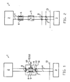
- Fig. 1 is a schematic representation of a system 1 according to the invention with at least one control electronics 2, a system module 3 and a plug-in module 9 with Sokkelteil 10, wherein plug-in module and base part simultaneously form a switching device 5.
- the electrical system 1 may have further of these components in a similar arrangement.
- Control electronics 2 and plug-in module 9 and base part 10 are usually arranged in a cabinet 13.
- the electrical connection line 4 may be formed by individual cables, a bus system or the like.
- the base part 10 is detachably mounted within the cabinet 13 and from this the plug-in module 9 with fuses 6 is separable, see line 69 in Fig. 1 ,
- first and second terminals 7, 8 are provided, can be connected to the system module 3 and control electronics 2 and are electrically connected when the plug-in module 9 is inserted.
- Another terminal 14 is provided as a so-called support terminal between each of the first and second terminals 7, 8, see Fig. 3 ,
- the electrical system 1 according to the invention is used in particular in potentially explosive areas, so-called Ex areas, in which plug-in connections in the type of protection "flameproof enclosure” are executed.
- FIG. 2 an electrical system 1 according to the prior art is shown.
- a number of different components are arranged in the electrical lines 4 between control electronics 2 and 3 investment module.
- a component is a fuse box with two fuses 6.
- Another component is a switching device 5 for interrupting the electrical connection lines 4.
- first and second terminals 7, 8 provided on the electrical connection lines 4, via which a power supply further electrical lines within the cabinet 13 takes place.
- Fig. 3 is the electrical system after Fig. 1 partially shown, wherein by means of the first terminals 7 and arranged therebetween support terminal 14, two contact modules 3, 15 are connected to the base part 10 via electrical lines. In this way, the plant modules can be selectively secured in parallel supply and separated individually from the voltage.
- FIG. 4 is a section along the line II Fig. 1 represented by a first embodiment of plug-in module 9 and base part 10. As stated above, plug-in module and base part simultaneously form a switching device 5 for interrupting the power supply.
- the base part 10 is formed by a base housing 16 of tub-like lower part 20 and base cover 21.
- the lower part 20 has on its rear side opposite the plug-in module 9 19 a snap-fastening device 18 for releasably securing the lower part 10 to a DIN rail 17.
- the base cover 21 is detachably connected to the open end of the lower part 20 with this and locked there.
- known terminals 7, 8 are arranged. These are connected via electrical connection lines 39 with contacts of a plug 22 in the form of a double socket 24.
- the Einstekk Anlagen 22 projecting from the plug-in module 9 Gegeneinsteck noticed 23 is detachably inserted.
- this plug pins 25 are arranged, which protrude from the plug-in module 9 in the direction of base part 10. Lateral spaced on both sides of the plug-in device 22 are from the base cover 21 latching arms 27, 28 as a latching device 26 from. These point towards each other and engage behind protrusions 31 projecting from outer sides 29, 30 of the plug-in module 9.
- the plug-in module 9 In the illustrated arrangement of the plug-in module 9 relative to the base part 10, the plug-in module 9 is arranged in its connection position 11. In this the furthest to the base cover 21 spaced latching projections 31 are engaged behind.
- the plug-in module 9 is formed by a box-shaped plug housing 32 with cover 34.
- the mating plug-in devices 23 are plug-like manner arranged with the Stekkerstatten 25 in plug-in recesses 36. These latch with the plug-in device 22 in plug-in module 9 arranged in connection position 11.
- the cover 34 of the plug-in module 9 has on one side a one-piece terminal cover 38, which extends in steps over the latching arm 28 and the second terminals 8 and covers them.
- a second terminal cover 37 covers the first terminals 7 opposite to the plug-in module 9, wherein both terminal covers 37, 38 may be formed integrally with the plug-in module 9.
- the latching projections 31 are from outer sides 29, 30 of the plug housing 32 from.
- plug-in module 9 and base part 10 For use of plug-in module 9 and base part 10 in hazardous areas formed by plug-in device 22 in Schmidteinsteck Pain 23 connectors in the ignition protection "flameproof enclosure" are executed. Other types of protection do not permit plugging in hazardous areas, except in "intrinsically safe” ignition protection circuits.
- the fuse (s) are detachably supported within the plug-in module 9 and connected to the plug pins 25 via electrical lines.
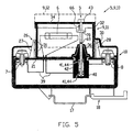
- Fig. 5 is a cut analogous to Fig. 4 represented by a second embodiment of plug-in module 9 and base part 10.
- Fig. 5 In contrast to Fig. 4 is in Fig. 5 also dashed the plug-in module 9 shown in the release position 12. In this position, the latching arms 27, 28 engage behind the latching projections 31 arranged closer to the base cover 21. In such a disconnected position, the plug-in module 9 retreats Fig. 4 so far separated from the base part 10, that the electrical connection between plug-in device 22 and Gegeneinsteck responded 23 is interrupted. In this condition, the flameproof enclosure is still preserved, as well as in FIG. 4 ,
- Fig. 5 differs further from the exemplary embodiment Fig. 4 in that the electrical connections between the fuse 6 and the first and second terminals 7, 8 are shown only in principle, these being analogous to Fig. 4 can be executed. However, these compounds can also be realized in other easily separable form.
- a particular flameproof capsule 40 is arranged, which is fixed in the base cover 21.
- spaced contact rings 44 are arranged as contact elements 41 from each other in the longitudinal direction of a contact pin.
- a lower one of these contact rings 44 is over one electrical connection line 39 connected to one end of the fuse 6 in the plug-in module 9. The other end of the fuse is connected to the first terminal 7.
- the upper contact ring 44 is connected via a further electrical connection line 39 to the second terminal 8.
- the contact pin 42 is inserted from the direction of the plug-in module 9. This is slidably mounted in the plug-in module 9.
- the contact pin 42 has at its upper end an actuator 43 which is made of an electrically insulating material.
- the actuating member 43 further has an annular shoulder 70, which limits the movement of the contact pin 42 relative to the plug-in module 9 in the direction of movement 66 by abutment against the cover 34.
- this may be formed above a marking 69 made of an electrically insulating material or be electrically separated from the remaining contact pin 42 in the region of the marking 69.
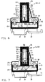
- Fig. 6 is a cut analogous to Fig. 4 represented by a third embodiment of plug-in module 9 and base part 10.
- the plug-in module 9 comprises a cap 46 and a lower part 45.
- the lower part 45 is arranged on the base cover 21 and there, for example, releasably secured.
- the cap 46 is detachably connected to the lower part 45 by screwing.
- the cap 46 has a cylindrical inner sleeve 51 which can be inserted into the lower part 45. This has at its lower end 52 on an external thread 53 which is screwed with a arranged on an inner side of the lower part 45 internal thread 54.
- the fuse 6 is arranged substantially in the longitudinal direction of the inner sleeve 51.
- a lower terminal contact 48 of the fuse 6 is connected to a first contact element 47 in Appendix. This is spring-loaded by a spring 68 in the direction of terminal contact 48 of the fuse 6.
- Cap 46 and lower part 45 form a flameproof enclosure.
- connection contact element 58 is part of a mating contact element 56, which contacts a second contact element 49 in the form of a sliding contact element 55 at the lower end 52 of the cap 46.
- First and second contact element 47, 49 are connected via corresponding electrical connecting lines 39 with first and second terminals 7, 8.
- the mating contact element 56 is formed by a sliding mating contact element 59, which extends only over a part of the circumference on an inner side 57 of the capsule 46.
- the sliding mating contact member 59 and the sliding contact member 55 slide along each other until a portion of the inner surface 57 of the cap 46 is reached where no abrasive mating contact member 59 is applied. There, the separation of the electrical connection between the first and second terminals 7, 8. After the cap 46 is rotated relative to the lower part 45 so far that the electrical connection is interrupted is, (separation position), the cap 46 can be solved by optionally further rotation relative to the lower part and removed from the base part 10.
- annular groove 63 is formed, see also Fig. 7 into which at least partially an annular flange 62 engages. This is integrally connected to the terminal cover 38 to cover the second terminals 8. When removing the cap 46 from the base part 10, this terminal cover 38 is also removable and at least the second terminals 8 are accessible.
- terminal cover 37 may be integrally formed with the terminal cover 38. In an alternative embodiment, the terminal cover 37 is detachable separately from the base member 10.
- the mating contact element 56 can be guided around into the area of the external thread 53 on an outer side of the inner sleeve 51.
- Fig. 7 is in a representation analogous to the section to 4 to 6 a fourth embodiment of plug-in module 9 and base part 10 is shown.
- a pressure-resistant chamber 60 is formed on a bottom of the lower part 45 opposite to the base cover 21, a pressure-resistant chamber 60 is formed.
- the contact pin 61 contacts the lower terminal contact 48 of the fuse 6.
- the contact pin 61 is at its opposite end of the fuse 6 with the first contact element 47 in electrical contact.
- Fig. 7 is different from the after Fig. 6
- the chamber 60 has a smaller volume compared to the interior of the cap 46. Such a smaller volume simplifies the practical implementation of the so-called "flameproof enclosure".
- the fuses 6 are preferably standardized, commercially available fuses. It should also be noted that both in the plug-in module 9 and in the base part 10 or at least in one of both additional electrical and / or electronic components may be arranged, such as bus terminators, voltage indicators, power indicators, polarity indicators or the like. Even with such additional electrical or electronic components, the unit of plug-in module / socket part is very compact and in particular the plug-in module can be easily carried by maintenance personnel or the like to protect against unintentional reconnection of the interrupted circuit. In addition, the first and second terminals 7, 8 are only accessible by the use of the terminal covers 37, 38, if at least the plug-in module 9 is removed. This fulfills the requirements of accident prevention protection in a simple manner and is particularly important when the investment module to be exchanged or serviced, such as a sensor or the like, is located far away from the control cabinet 13 or the base part 10.
Landscapes
- Details Of Connecting Devices For Male And Female Coupling (AREA)
- Fuses (AREA)
- Iron Core Of Rotating Electric Machines (AREA)
- Control Of Linear Motors (AREA)
- Connector Housings Or Holding Contact Members (AREA)
Description
- Die Erfindung betrifft eine elektrische Anlage mit zumindest einer Steuerelektronik und einem mit dieser verbindbaren Anlagemodul, wobei in einer elektrischen Verbindungsleitung zwischen Steuerelektronik und Anlagemodul wenigstens eine Schalteinrichtung und eine Sicherung sowie Klemmen zum Anschluss des Anlagemoduls an die elektrische Verbindungsleitung angeordnet ist.
- Eine solche elektrische Anlage muss vor Beginn von Wartungsarbeiten, Reparaturen oder dergleichen spannungsfrei geschaltet werden. Dies erfolgt über eine Schalteinrichtung, die die elektrische Verbindung zwischen Anlagemodul und Steuerelektronik unterbricht. Anschließend kann beispielsweise das Anlagemodul gewartet oder ausgetauscht werden oder andere Bauteile zwischen Sicherungselektronik und Anlagemodul können gewartet oder ausgetauscht werden.
- Eine solche Spannungsfreischaltung der elektrischen Anlage ist insbesondere in solchen Bereichen notwendig, in denen Explosionsgefahr besteht, d.h. in sogenannten Ex-Bereichen.
- Durch das Spannungsfreischalten wird ein Prozessablauf der elektrischen Anlage insbesondere bei kontinuierlich ablaufenden Prozessen unterbrochen, wodurch die elektrische Anlage während dieser Unterbrechung im Wesentlichen stillsteht. Dies führt zu erhöhten Kosten. Außerdem ist die elektrisch Anlage durch die Vielzahl der Bauteile, wie beispielsweise die Schalteinrichtung für jedes Anlagemodul und die zusätzliche Verdrahtung einer solchen Schalteinrichtung relativ komplex aufgebaut, was zu zusätzlichen Kosten für die vielen verschiedenen Bauteile und bei deren zeitaufwendiger Montage führt.
-
US-A-1,482,958 offenbart einen elektrischen Schalter mit einem Unterteil und einem an diesem verschwenkt gelagerten Oberteil. ImUnterteil sind in einem Verbindungsblock Kontakte zum Anschluss von externen Leitungen vorgesehen. Der Verbindungsblock wird durch einen Abdeckungsblock abgedeckt, wobei der Abdeckungsblock nur entsprechende Öffnungen zum Durchstecken beispielsweise von Verbindungsschneiden aufweist. Die Verbindungsschneiden sind in einem im Oberteil beweglich gelagerten Schaltblock angeordnet. Der Schaltblock weist auf seiner dem Unterteil zuweisenden Seite eine offene Ausnehmung auf, in der zwei Sicherungen gehalten sind. Der Schaltblock ist von außen über eine entsprechende Handhabe im Oberteil beweglich. - Dokument
EP-A-0852388 offenbart eine elektrische Anlage gemäß dem Oberbegriff des Anspruchs 1. - Der Erfindung liegt die Aufgabe zu Grunde, eine elektrische Anlage der eingangs genannten Art dahingehend zu verbessern, dass diese vereinfacht aufgebaut ist und ein Abschalten der elektrischen Anlage soweit wie möglich vermieden wird, wobei die elektrische Anlage gleichzeitig preiswerter herstellbar und betreibbar ist.
- Diese Aufgabe wird durch die Merkmale des Patentanspruchs 1 gelöst.
- Erfindungsgemäß kann das Steckmodul mit Sicherungen in einfacher Weise vom Sockelteil gelöst werden, wodurch bereits die elektrische Verbindung zwischen Steuerelektronik und Anlagemodul unterbrochen wird. Durch das Entfernen des Steckmoduls wird außerdem nur diese elektrische Verbindung unterbrochen und nicht die gesamte Anlage oder größere Anlagenteile spannungsfrei geschaltet. Durch die Anordnung der Klemmen im oder am Sockelteil dient dieses außerdem zum elektrischen Anschließen des Anlagemoduls und der Steuerelektronik, so dass separat angeordnete Klemmen entfallen können. Auf Grund dieser einfachen Weise der Spannungsfreischaltung können einzelne Anlagemodule zu Wartungszwecken, Reparaturen oder dergleichen schnell und sicher von der elektrischen Anlage getrennt werden.
- Das Steckmodul ist außerdem sehr kompakt und kann vom Wartungspersonal mitgeführt werden, um ein unbeabsichtigtes Wiedereinschalten des Anlagemoduls zu verhindern. Dies ist insbesondere dann wichtig, wenn das Anlagemodul relativ weit entfernt vom Sockelteil und Steckmodul angeordnet ist, was in der Regel der Fall ist.
- Bei Einsatz im Ex-Bereich ist es außerdem wichtig, dass zuerst das entsprechende Anlagemodul spannungsfreigeschaltet wird und dann erst die Sicherung vollständig entfernt wird. Dies erfolgt erfindungsgemäß dadurch, dass das Steckmodul gleichzeitig als Schalteinrichtung ausgebildet ist. Zuerst wird das Steckmodul aus seiner Verbindungsstellung in die Trennstellung bewegt, wodurch eine Spannungsfreischaltung des Anlagemoduls erfolgt.
- Zündfähige Funken, die bei diesem Spannungsfreischalten auftreten können, sind entsprechend EN 50018 druckfest gekapselt und werden vor dem tatsächlichen Entnehmen des Steckmoduls abkühlen. Erst anschließend wird das Steckmodul aus seiner Trennstellung entfernt und vom Sockelteil getrennt. Auf diese Weise ist erfindungsgemäß keine zusätzliche Anordnung einer Schalteinrichtung notwendig, durch die vor Entnahme des Steckmodul eine Spannungsfreischaltung des entsprechenden Anlagemoduls erfolgen müsste.
- Durch den entsprechenden Sockeldeckel, der das wannenartige Unterteil verschließt, ergibt sich eine vereinfachte Zugänglichkeit der Klemmen, wobei diese im Sockeldeckel angeordnet sind.
- Weiterhin erfolgt auch das Einstecken des Steckmoduls direkt über eine Einsteckeinrichtung im Sockeldeckel, wobei das Steckmodul mit einer entsprechenden Gegeneinsteckeinrichtung lösbar und Anlagemodul und Steuerelektronik verbindend einsteckbar ist.
- In einem einfachen Anwendungsmodul können Steuerelektronik und Sockelteil sowie in diesem eingestecktes Steckmodul in einem Schaltschrank angeordnet sein. Es ist selbstverständlich, dass eine Vielzahl von solchen Bauteilen in dem Schaltschrank enthalten sein können. Die entsprechenden Anlagemodule, wie beispielsweise Sensoren oder dergleichen, können weit entfernt vom Schaltschrank vor Ort im Ex-Bereich angeordnet und über entsprechende Verbindungsleitungen, wie elektrische Verkabelung, Bussysteme oder dergleichen mit dem Schaltschrank und entsprechend mit Sockelteil und Steuerelektronik verbunden sein.
- Um ein Sockelteil für mehr als ein Anlagemodul einsetzen zu können, kann das Sockelteil wenigstens eine Stützklemme zum seriellen Anschluss von zwei Anlagemodulen aufweisen.
- Zum Anbringen verschiedenster elektrischer oder elektronischer Bauteile, insbesondere in Schaltschränken, sind genormte Schienen vorgesehen, durch die die Bauteile gehalten und an die die Bauteile einfach anbringbar sind. Erfindungsgemäß kann das Sockelteil ein Sockelgehäuse aufweisen, das auf eine solche DIN-Schiene beispielsweise aufschnappbar ist. Andere Verbindungen zwischen Sockelteil bzw. Sockelgehäuse und Schiene sind offensichtlich.
- Zur einfachen Realisierung einer solchen Schnappverbindung kann eine Schnappbefestigungseinrichtung auf einer Rückseite des Sockelgehäuses angeordnet sein.
- Die Einsteckeinrichtung kann in mannigfacher Weise aufgebaut sein. Bei einem einfachen Ausführungsbeispiel kann sie beispielsweise eine Doppelsteckbuchse aufweisen, in die vom Steckmodul nach außen vorstehende Steckerstifte einsteckbar sind.
- Bei Einsatz der erfindungsgemäßen Anlage im Ex-Bereich, d.h. in Bereichen mit Explosionsschutz, muss die Steckverbindung zwischen Steckmodul und Sockelteil in der Zündschutzart "druckfeste Kapselung" ausgeführt sein, da andere Zündschutzarten kein Stecken unter Last im Ex-Bereich erlauben, außer in Stromkreisen der Zündschutzart "Eigensicherheit". Ist daher die Doppelsteckbuchse bzw. die Einsteckeinrichtung druckfest gekapselt (EN 50018), kann eine solche Steckverbindung auch bei vorhandenem explosiven Gemisch im Bereich der elektrischen Anlage hergestellt oder getrennt werden.
- Um durch ein einfaches Ausführungsbeispiel Verbindungs- und Trennstellung des Steckmoduls zu ermöglichen, kann das Sockelteil eine Rasteinrichtung aufweisen, mit der das Steckmodul in Verbindungs- und Trennstellung lösbar verrastet ist und durch welche beide Stellungen gleichzeitig bestimmt sind.
- Bei einem Ausführungsbeispiel für eine solche Rasteinrichtung kann diese zwei aufeinander zuweisendem vom Sockeldeckel nach außen abstehende Rastarme aufweisen, die mit auf gegen überliegenden Außenseiten des Steckmoduls angeordneten Rastvorsprüngen in Anlage bringbar sind. Es sei nochmals angemerkt, daß diese Art der Rasteinrichung sicherstellt, daß erst in der Trennstellung das Anlagemodul abgeschaltet und anschließend das Steckmodul aus der Trennstellung vom Sockelteil entfernt werden kann.
- Ein einfach und preiswert aufgebautes Steckmodul kann dadurch realisiert werden, daß dieses ein kastenförmiges Steckgehäuse aufweist, das auf seiner vom Sockelteil fortweisenden Vorderseite durch einen Deckel verschließbar ist. In dem Steckmodul ist die Sicherung in an sich bekannter Weise beispielsweise zwischen zwei federnden Kontakten gehalten.
- Um Steckmodul und Sockelteil in einfacher Weise einander zur Herstellung der Steckverbindung zuordnen zu können, kann das Steckgehäuse in seiner dem Sockelteil zuweisenden Rückseite Steckausnehmungen aufweisen, in denen die Steckerstifte vorstehen und die auf die Steckerbuchsen im Sockelteil aufsteckbar sind.
- Wie bereits erwähnt, können die Klemmen zum Anschließen von Anlagemodul und Steuerelektronik direkt im Sockeldeckel angeordnet sein. Um zu verhindern, daß die Klemmen bereits vor einem Entfernen des Steckmoduls zugänglich sind, können Steckgehäuse und/oder Sockelgehäuse Klemmenabdeckungen für die Klemmen aufweisen. Dadurch sind die Klemmen erst nach Entfernen der Klemmabdeckungen erreichbar, wodurch in einfacher Weise die Anforderungen des Unfallverhütungsschutzes erfüllt werden. Ist eine solche Klemmabdeckung mit dem Steckgehäuse verbunden, werden die Klemmen durch Entfernen des Steckmoduls freigegeben und sind dann zugänglich.
- Um in einfacher Weise eine elektrische Verbindung zwischen den Klemmen für Anlagemodul und Steuerelektronik innerhalb des Sockelteils herzustellen, können elektrische Verbindungsleitungen zwischen den Klemmen und der Einsteckeinrichtung im Sockelgehäuse angeordnet sein.
- Aufgrund der Kompaktheit des Steckmoduls und des Sockelteils ist es außerdem möglich, daß wenigstens eine Klemmenabdeckung einteilig mit dem Deckel ausgebildet ist, so daß bei Entnahme des Steckmoduls zumindest einige der Klemmen direkt freigegeben werden.
- Bei einem weiteren Ausführungsbeispiel der Erfindung kann die Einsteckeinrichtung als druckfeste Kapsel ausgebildet sein, in der mit den Klemmen elektrisch verbindbare Kontaktelemente beabstandet voneinander angeordnet sind, wobei eine elektrische Verbindung der Kontaktelemente durch einen in die Kapsel beweglich einschiebbaren Kontaktstift herstellbar ist. Eine elektrische Verbindung zu der in dem Steckmodul enthaltenen Sicherung kann separat beispielsweise in der vorangehend beschriebenen Weise erfolgen. Durch entsprechendes Verschieben des Kontaktstiftes als Schalteinrichtung wird zuerst die elektrische Verbindung zwischen Anlagemodul und Steuerelektronik unterbrochen und dann kann das Steckmodul vom Sockelteil getrennt werden.
- Bei einem einfachen Ausführungsbeispiel kann der Kontaktstift aus dem Steckmodul hervorstehen. In diesem Fall kann wiederum durch Bewegen des Steckmoduls aus der Verbindungsstellung in die Trennstellung der Kontaktstift relativ zu den Kontaktelementen in der Kapsel soweit bewegt werden, daß die elektrische Verbindung getrennt ist. Durch anschließende Entnahme des Steckmoduls aus der Trennstellung und vollständige Trennung vom Sockelteil kann das Steckmodul dann mitgeführt werden, um ein zufälliges Wiedereinstecken in die Verbindungsstellung zu vermeiden.
- Um den Kontaktstift bereits vor Verstellen des Steckmoduls von Verbindungsstellung in Trennstellung zu bewegen, kann der Kontaktstift mit einem aus insbesondere der Vorderseite des Steckgehäuses oder dessen Deckel vorstehenden Betätigungsorgan bewegungsverbunden sein. Über dieses Betätigungsorgan ist dann der Kontaktstift soweit relativ zu den Kontaktelementen verstellbar, daß die elektrische Verbindung getrennt wird. Danach kann dann beispielsweise das Steckmodul vollständig vom Sockelteil entfemt oder zumindest in die obenerwähnte Trennstellung verstellt werden. Es sei angemerkt, daß das Betätigungsorgan beispielsweise ein elektrisch isolierender Teil des Kontaktstiftes sein kann, welcher Teil zumindest teilweise aus dem Steckmodul vorsteht.
- Eine einfache Ausbildung von mit dem Kontaktstift elektrisch verbindbaren Kontaktelementen ergibt sich beispielsweise dann, wenn die Kontaktelemente aus übereinander in der Kappe angeordneten Kontaktringen gebildet sind. In der Spannungsfreischaltstellung ist der Kontaktstift nur mit einem dieser Kontaktringe in Kontakt und in der Spannungsverbindungsstellung stellt er den Kontakt zwischen den beiden Kontaktringen her. Diese wiederum sind analog wie bereits vorangehend ausgeführt, mit den Klemmen zum Anschluß von Anlagemodul und Steuerelektronik elektrisch verbunden.
- Bei einem weiteren Ausführungsbeispiel der Erfindung kann das Steckmodul ein hülsenförmiges Unterteil und eine diesem lösbar aufsetzbare Kappe aufweisen, wobei die mit den Klemmen elektrisch verbundenen Kontaktelemente im Unterteil angeordnet und bei aufgesetzter Kappe über die in der Kappe lösbar gehalterte Sicherung verbunden sind. In diesem Fall wird die Kappe mit Sicherung entfernt, falls eine Spannungsfreischaltung des Anlagemoduls erwünscht ist. Das Unterteil des Steckmoduls mit den darin angeordneten Kontaktelementen kann an dem Sockelteil verbleiben. Die elektrische Kontaktierung zum Steckmodul erfolgt beispielsweise dadurch, daß das erste Kontaktelement direkt mit einem Anschlußkontakt der Sicherung und das zweite Kontaktelement über ein innerhalb der Kappe angeordnetes Gegenkontaktelement mit dem anderen Anschlußkontakt der Sicherung in Verbindung ist.
- Eine einfache Art der lösbaren Befestigung von Kappe am Unterteil ergibt sich dadurch, daß diese miteinander verschraubbar sind.
- Um beim Trennen von Kappe und Unterteil nicht direkt das Innere des Steckmoduls zu öffnen, kann die Kappe eine in das Unterteil einsetzbare, nach unten offene Innenhülse aufweisen, welche an ihrem unteren Ende ein Außengewinde zum Verschrauben mit einem innerhalb des Unterteils ausgebildeten Innengewinde aufweist. Der zylindrische Spalt zwischen Innenhülse und Unterteil bildet den Spalt für die druckfeste Kapselung.
- Um während des Verdrehens der Kappe relativ zum Unterteil die elektrische Verbindung herzustellen, kann das zweite Kontaktelement ein an einer Innenseite der Innenhülse anliegendes Schleifkontaktelement aufweisen.
- Um bereits nach einem teilweisen Verdrehen der Kappe relativ zum Unterteil die elektrische Verbindung noch vor Entnahme des Steckmoduls beziehungsweise der Kappe zum Sockelteil zu unterbrechen, kann das Gegenkontaktelement ein auf der Innenseite aufgebrachtes, sich über einen Teil des Innenumfangs erstreckendes Schleifgegenkontaktelement und ein sich von diesem bis zum anderen Anschlußkontakt der Sicherung erstreckendes Verbindungskontaktelement umfassen. Die elektrische Verbindung besteht dabei solange, wie Schleifkontaktelement und Schleifgegenkontaktelement in Berührung sind.
- In diesem Zusammenhang ist es als vorteilhaft zu betrachten, wenn das Verbindungskontaktelement im Bereich des anderen Anschlußkontaktes der Sicherung eine elastische Einsteckaufnahme bildet. Diese dient zur lösbaren Halterung eines Endes der Sicherung, wodurch diese auch beim Lösen der Kappe vom Unterteil sicher in der Kappe gehalten und mit dieser handhabbar ist.
- Um beim Aufschrauben der Kappe auf das Unterteil eine Verbindung zum ersten Kontaktelement sicher herzustellen, kann dieses in Richtung Sicherung federbeaufschlagt sein.
- Bei einem noch weiteren Ausführungsbeispiel der Erfindung kann das erste Kontaktelement innerhalb des Unterteils in einer druckfesten Kammer angeordnet sein, aus der in Richtung Sicherung ein Kontaktstift vorsteht. Hierzu ist zu beachten, daß je kleiner das Volumen der druckfesten Kapselung ist, desto einfacher ist die praktische Ausführung. Die Unterbrechung des Stromkreises erfolgt demgemäß zunächst in dieser separaten druckfesten Kammer, bevor der weitere Kontakt zwischen Kappe und Unterteil durch deren relative Verdrehung zueinander unterbrochen wird.
- Um den Kontaktstift bei Abschrauben der Kappe vom ersten Kontaktelement zu trennen und gleichzeitig eine sichere Verbindung zur Sicherung herstellen zu können, kann der Kontaktstift relativ zum ersten Kontaktelement beweglich gelagert und in Richtung Sicherung federbeaufschlagt sein. Bei Abschrauben der Kappe wird aufgrund der Federbeaufschlagung der Kontaktstift von dem ersten Kontaktelement getrennt und gerät schließlich in Anlage mit einer Wand der Kammer, woraufhin durch weiteres Abschrauben der Kappe auch der Kontakt zwischen Kontaktstift und Sicherung unterbrochen wird.
- Um auch bei diesem Ausführungsbeispiel zusammen mit der Kappe eine Klemmenabdeckung handhaben zu können, kann diese an der Kappe drehbar gehaltert sein. Dadurch ist ein freies Drehen von Kappe relativ zur Klemmenabdeckung zum Lösen der Kappe vom Unterteil möglich und nach Lösen kann die Klemmenabdeckung zusammen mit der Kappe entfernt werden.
- Eine einfach drehbare Halterung der Klemmenabdeckung an der Kappe ist beispielsweise dadurch realisierbar, daß die Klemmenabdeckung einen Ringflansch aufweist, der zumindest teilweise in einer Ringnut im Außenumfang der Kappe drehbar eingesteckt ist.
- Steckmodul und Sockelteil gemäß der Erfindung sind zwar kompakt und relativ klein ausgebildet. Allerdings ist es dennoch möglich, gegebenenfalls weitere elektrische und/oder elektronische Bauteile, wie Busabschlußwiderstand, Spannungsanzeige, Stromanzeige, Polaritätsindikator oder dergleichen im Steckmodul und/oder im Sockelteil anzuordnen.
- Im folgenden werden vorteilhafte Ausführungsbeispiele der Erfindung anhand der in der Zeichnung beigefügten Figuren näher erläutert und beschrieben.
- Es zeigen:
- Fig. 1
- eine prinzipielle Darstellung einer zumindest Steuerelektronik, Steckmodul, Sockelteil und Anlagemodul umfassenden, erfindungsgemäßen elektrischen Anlage;
- Fig. 2
- eine elektrische Anlage, wie sie aus der Praxis bekannt ist;
- Fig. 3
- eine teilweise Darstellung analog zu
Fig. 1 mit zwei Anlagemodulen; - Fig. 4
- einen Schnitt entlang der Linie I-I aus
Fig. 1 für ein erstes Ausführungsbeispiel von Steckmodul und Sockelteil; - Fig. 5
- einen Schnitt analog zu
Fig. 4 durch ein zweites Ausführungsbeispiel von Steckmodul und Sockelteil; - Fig. 6
- einen Schnitt analog zu
Fig. 4 durch ein drittes Ausführungsbeispiel von Steckmodul und Sockelteil; und - Fig. 7
- einen Schnitt analog zu
Fig. 4 durch ein viertes Ausführungsbeispiel von Steckmodul und Sockelteil. - In
Fig. 1 ist eine prinzipielle Darstellung einer erfindungsgemäßen Anlage 1 mit wenigstens einer Steuerelektronik 2, einem Anlagemodul 3 und einem Steckmodul 9 mit Sokkelteil 10 dargestellt, wobei Steckmodul und Sockelteil gleichzeitig eine Schalteinrichtung 5 bilden. Die elektrische Anlage 1 kann weitere dieser Bauelemente in ähnlicher Anordnung aufweisen. - Steuerelektronik 2 sowie Steckmodul 9 und Sockelteil 10 sind in der Regel in einem Schaltschrank 13 angeordnet. Die elektrische Verbindung zwischen Steuerelektronik 2 und Anlagemodul 3 erfolgt über elektrische Verbindungsleitungen 4, wobei Steckmodul und Sockelteil in der elektrischen Verbindungsleitung angeordnet sind. Die elektrische Verbindungsleitung 4 kann durch einzelne Kabel, ein Bussystem oder dergleichen gebildet sein.
- Das Sockelteil 10 ist innerhalb des Schaltschranks 13 lösbar befestigt und von diesem ist das Steckmodul 9 mit Sicherungen 6 trennbar, siehe Zeile 69 in
Fig. 1 . Am Sockelteil 10 sind erste und zweite Klemmen 7, 8 vorgesehen, an die Anlagemodul 3 und Steuerelektronik 2 anschließbar und bei eingestecktem Steckmodul 9 elektrisch verbunden sind. - Eine weitere Klemme 14 ist als sogenannte Stützklemme zwischen jeweils den ersten und zweiten Klemmen 7, 8 vorgesehen, siehe hierzu
Fig. 3 . - An dieser Stelle sei angemerkt, daß die elektrische Anlage 1 gemäß Erfindung insbesondere in explosionsgefährdeten Bereichen, sogenannten Ex-Bereichen, eingesetzt wird, bei denen Steckverbindungen in der Zündschutzart "druckfeste Kapselung" ausgeführt sind.
- In
Fig. 2 ist eine elektrische Anlage 1 nach Stand der Technik dargestellt. Bei dieser sind in den elektrischen Leitungen 4 zwischen Steuerelektronik 2 und Anlagemodul 3 eine Reihe unterschiedlicher Bauteile angeordnet. Ein Bauteil ist ein Sicherungskasten mit zwei Sicherungen 6. Ein weiteres Bauteil ist eine Schalteinrichtung 5 zum Unterbrechen der elektrischen Verbindungsleitungen 4. Schließlich sind innerhalb des Schaltschranks 13 noch erste und zweite Klemmen 7, 8 an den elektrischen Verbindungsleitungen 4 vorgesehen, über die eine Spannungsversorgung durch weitere elektrische Leitungen innerhalb des Schaltschranks 13 erfolgt. - In
Fig. 3 ist die elektrische Anlage nachFig. 1 teilweise dargestellt, wobei mittels der ersten Klemmen 7 und der dazwischen angeordneten Stützklemme 14 zwei Anlagemodule 3, 15 mit dem Sockelteil 10 über elektrische Leitungen verbunden sind. Auf diese Weise können die Anlagemodule bei paralleler Speisung selektiv abgesichert und einzeln von der Spannung getrennt werden. - In
Fig. 4 ist ein Schnitt entlang der Linie I-I ausFig. 1 durch ein erstes Ausführungsbeispiel von Steckmodul 9 und Sockelteil 10 dargestellt. Wie bereits oben ausgeführt, bilden Steckmodul und Sockelteil gleichzeitig eine Schalteinrichtung 5 zur Unterbrechung der Spannungsversorgung. - In
Fig. 4 wie in den folgendenFig. 5 - 7 sind gleiche Teile mit den gleichen Bezugszeichen versehen und werden in den folgenden Figuren nur noch teilweise erwähnt. - Das Sockelteil 10 ist durch ein Sockelgehäuse 16 aus wannenartigem Unterteil 20 und Sockeldeckel 21 gebildet. Das Unterteil 20 weist auf seiner dem Steckmodul 9 gegenüberliegenden Rückseite 19 eine Schnappbefestigungseinrichtung 18 zur lösbaren Befestigung des Unterteils 10 an einer DIN-Schiene 17 auf.
- Der Sockeldeckel 21 ist am offenen Ende des Unterteils 20 mit diesem lösbar verbunden und dort verriegelt. In dem Sockeldeckel 21 sind an sich bekannte Klemmen 7, 8 angeordnet. Diese sind über elektrische Verbindungsleitungen 39 mit Kontakten einer Einsteckeinrichtung 22 in Form einer Doppelsteckbuchse 24 verbunden. In die Einstekkeinrichtung 22 ist eine vom Steckmodul 9 vorstehende Gegeneinsteckeinrichtung 23 lösbar eingesteckt. In dieser sind Steckerstifte 25 angeordnet, die vom Steckmodul 9 in Richtung Sockelteil 10 vorstehen. Seitlich beidseitig beabstandet zur Einsteckeinrichtung 22 stehen von dem Sockeldeckel 21 Rastarme 27, 28 als Rasteinrichtung 26 ab. Diese weisen aufeinander zu und hintergreifen von Außenseiten 29, 30 des Steckmoduls 9 abstehende Rastvorsprünge 31.
- Bei der dargestellten Anordnung des Steckmoduls 9 relativ zum Sockelteil 10 ist das Steckmodul 9 in seiner Verbindungsstellung 11 angeordnet. In dieser werden die am weitesten zum Sockeldeckel 21 beabstandeten Rastvorsprünge 31 hintergriffen.
- Das Steckmodul 9 ist durch ein kastenförmiges Steckgehäuse 32 mit Deckel 34 gebildet. In einer dem Sockeldeckel 21 zuweisenden Rückseite des Steckgehäuses 32 sind in Steckausnehmungen 36 die Gegensteckeinrichtungen 23 steckerartig mit den Stekkerstiften 25 angeordnet. Diese verrasten mit der Einsteckeinrichtung 22 bei in Verbindungsstellung 11 angeordnetem Steckmodul 9.
- Der Deckel 34 des Steckmoduls 9 weist einseitig eine einteilige Klemmenabdeckung 38 auf, die sich stufenförmig über den Rastarm 28 und die zweiten Klemmen 8 erstreckt und diese überdeckt. Eine zweite Klemmenabdeckung 37 überdeckt die ersten Klemmen 7 gegenüberliegend zum Steckmodul 9, wobei beide Klemmenabdeckungen 37, 38 einteilig mit dem Steckmodul 9 ausgebildet sein können.
- Die Rastvorsprünge 31 stehen von Außenseiten 29, 30 des Steckgehäuses 32 ab.
- Zur Anwendung von Steckmodul 9 und Sockelteil 10 in Ex-Bereichen sind die durch Einsteckeinrichtung 22 in Gegeneinsteckeinrichtung 23 gebildeten Steckverbindungen in der Zündschutzart "druckfeste Kapselung" ausgeführt. Andere Zündschutzarten erlauben kein Stecken im Ex-Bereich, außer in Stromkreisen der Zündschutzart "Eigensicherheit".
- Die Sicherung(en) sind innerhalb des Steckmoduls 9 lösbar gehaltert und über elektrische Leitungen mit den Steckerstiften 25 verbunden.
- In
Fig. 5 ist ein Schnitt analog zurFig. 4 durch ein zweites Ausführungsbeispiel von Steckmodul 9 und Sockelteil 10 dargestellt. - Im Unterschied zu
Fig. 4 ist inFig. 5 außerdem gestrichelt das Steckmodul 9 in Trennstellung 12 dargestellt. In dieser Stellung hintergreifen die Rastarme 27, 28 die näher zum Sockeldeckel 21 angeordneten Rastvorsprünge 31. In einer solchen Trennstellung ist das Steckmodul 9 nachFig. 4 soweit vom Sockelteil 10 getrennt, daß die elektrische Verbindung zwischen Einsteckeinrichtung 22 und Gegeneinsteckeinrichtung 23 unterbrochen ist. In diesem Zustand ist die druckfeste Kapselung aber noch erhalten, wie auch inFigur 4 . - Das Ausführungsbeispiel nach
Fig. 5 unterscheidet sich weiterhin vom Ausführungsbeispiel nachFig. 4 dadurch, daß die elektrischen Verbindungen zwischen Sicherung 6 und ersten und zweiten Klemmen 7, 8 nur prinzipiell dargestellt sind, wobei diese analog zuFig. 4 ausgeführt sein können. Allerdings können diese Verbindungen auch in anderer leicht trennbarer Form realisiert werden. - In dem Ausführungsbeispiel nach
Fig. 5 ist im Sockelteil 10 eine insbesondere druckfeste Kapsel 40 angeordnet, die im Sockeldeckel 21 befestigt ist. Innerhalb der Kapsel 40 sind voneinander in Längsrichtung eines Kontaktstiftes 42 beabstandete Kontaktringe 44 als Kontaktelemente 41 angeordnet. Ein unterer dieser Kontaktringe 44 ist über eine elektrische Verbindungsleitung 39 mit einem Ende der Sicherung 6 im Steckmodul 9 verbunden. Das andere Ende der Sicherung ist mit der ersten Klemme 7 verbunden. Der obere Kontaktring 44 ist über eine weitere elektrische Verbindungsleitung 39 mit der zweiten Klemme 8 verbunden. - In die Kapsel 40 ist aus Richtung des Steckmoduls 9 der Kontaktstift 42 eingesteckt. Dieser ist im Steckmodul 9 verschiebbar gelagert. Zur Lagerung dienen die Steckausnehmung 36 des Steckgehäuses 32 und eine Öffnung im Deckel 34 des Steckmoduls 9. Der Kontaktstift 42 weist an seinem oberen Ende ein Betätigungsorgan 43 auf, das aus einem elektrisch isolierenden Material hergestellt ist. Mittels dieses Betätigungsorgans 43 ist der Kontaktstift 42 in Richtung 66 relativ zum Steckmodul 9 in Verbindungsstellung 11 verschiebbar. Das Betätigungsorgan 43 weist weiterhin eine Ringschulter 70 auf, die die Bewegung des Kontaktstiftes 42 relativ zum Steckmodul 9 in Bewegungsrichtung 66 durch Anlage an den Deckel 34 begrenzt. Zur elektrischen Isolierung des Betätigungsorgans 43 kann dieses oberhalb einer Markierung 69 aus einem elektrisch isolierenden Material gebildet oder im Bereich der Markierung 69 elektrisch vom übrigen Kontaktstift 42 getrennt sein.
- In der in
Fig. 5 dargestellten Stellung des Kontaktstiftes 42 bildet dieser eine elektrische Verbindung zwischen den voneinander beabstandeten Kontaktringen 44, so daß der Stromkreis zwischen ersten und zweiten Klemmen 7, 8 über die Sicherung 6 geschlossen ist. Bei Anlage der Ringschulter 70 von unten am Deckel 34 bzw. bei Steckmodul 9 in gestrichelt dargestellter Trennstellung 12 ist der Kontaktstift 42 nur noch in Kontakt mit einem Kontaktring 44, d.h. dem oberen direkt dem Sockeldeckel 21 benachbarten Kontaktring. Dadurch ist der elektrische Stromkreis zwischen erster und zweiter Klemme 7, 8 unterbrochen. - Eine solche Unterbrechung des elektrischen Stromkreises vor tatsächlichem Entfernen des Steckmoduls 9 ist für Ex-Bereiche wichtig, da Funken, die beim Unterbrechen des Stromkreises auftreten können, vor dem Öffnen bzw. Entfernen des Steckmoduls 9 abkühlen müssen.
- In
Fig. 6 ist ein Schnitt analog zurFig. 4 durch ein drittes Ausführungsbeispiel von Steckmodul 9 und Sockelteil 10 dargestellt. - In diesem Fall umfaßt das Steckmodul 9 eine Kappe 46 und ein Unterteil 45. Das Unterteil 45 ist auf dem Sockeldeckel 21 angeordnet und dort beispielsweise lösbar befestigt. Die Kappe 46 ist mit dem Unterteil 45 durch Verschrauben lösbar verbunden. Die Kappe 46 weist eine in das Unterteil 45 einsteckbare, zylindrische Innenhülse 51 auf. Diese weist an ihrem unteren Ende 52 ein Außengewinde 53 auf, das mit einem auf einer Innenseite des Unterteils 45 angeordneten Innengewinde 54 verschraubbar ist.
- Innerhalb der Kappe 46 ist die Sicherung 6 im wesentlichen in Längsrichtung der Innenhülse 51 angeordnet. Ein unterer Anschlußkontakt 48 der Sicherung 6 ist mit einem ersten Kontaktelement 47 in Anlage. Dieses ist durch eine Feder 68 in Richtung Anschlußkontakt 48 der Sicherung 6 federbeaufschlagt. Kappe 46 und Unterteil 45 bilden dabei eine druckfeste Kapselung.
- Der andere Anschlußkontakt 50 der Sicherung 6 ist in einem federelastischen Verbindungskontaktelement 58 lösbar gehalten. Das Verbindungskontaktelement 58 ist Teil eines Gegenkontaktelements 56, das am unteren Ende 52 der Kappe 46 ein zweites Kontaktelement 49 in Form eines Schleifkontaktelements 55 kontaktiert. Erstes und zweites Kontaktelement 47, 49 sind über entsprechende elektrische Verbindungsleitungen 39 mit ersten und zweiten Klemmen 7, 8 verbunden.
- Im Bereich des Schleifkontaktelements 55 ist das Gegenkontaktelement 56 durch ein Schleifgegenkontaktelement 59 gebildet, das sich nur über einen Teil des Umfangs auf einer Innenseite 57 der Kapsel 46 erstreckt. Bei Verdrehen der Kappe 46 relativ zum Unterteil 45 gleiten Schleifgegenkontaktelement 59 und Schleifkontaktelement 55 aneinander entlang, bis ein Bereich der Innenseite 57 der Kappe 46 erreicht ist, auf dem kein Schleifgegenkontaktelement 59 aufgebracht ist. Dort erfolgt die Trennung der elektrischen Verbindung zwischen ersten und zweiten Klemmen 7, 8. Nachdem die Kappe 46 soweit relativ zum Unterteil 45 verdreht ist, daß die elektrische Verbindung unterbrochen ist,(Trennstellung) kann die Kappe 46 durch gegebenenfalls weiteres Verdrehen relativ zum Unterteil gelöst und vom Sockelteil 10 entfernt werden.
- In einem Außenumfang 64 der Kappe 46 ist eine Ringnut 63 ausgebildet, siehe auch
Fig. 7 , in die zumindest teilweise ein Ringflansch 62 eingreift. Dieser ist einteilig mit der Klemmenabdeckung 38 zur Abdeckung der zweiten Klemmen 8 verbunden. Bei Entfernen der Kappe 46 vom Sockelteil 10 ist diese Klemmenabdeckung 38 ebenfalls entfembar und zumindest die zweiten Klemmen 8 sind zugänglich. - Es sei angemerkt, daß die Klemmenabdeckung 37 auch einteilig mit der Klemmenabdeckung 38 ausgebildet sein kann. Bei einem alternativen Ausführungsbeispiel ist die Klemmenabdeckung 37 separat zum Sockelteil 10 abnehmbar.
- Das Gegenkontaktelement 56 kann bis in den Bereich des Außengewindes 53 auf eine Außenseite der Innenhülse 51 herumgeführt sein.
- In
Fig. 7 ist in einer Darstellung analog zum Schnitt nachFig. 4 bis 6 ein viertes Ausführungsbeispiel von Steckmodul 9 und Sockelteil 10 dargestellt. - Dieses unterscheidet sich insbesondere vom Ausführungsbeispiel nach
Fig. 6 dadurch, daß auf einem Boden des Unterteils 45 gegenüberliegend zum Sockeldeckel 21 eine druckfeste Kammer 60 ausgebildet ist. In dieser ist das erste Kontaktelement 47 sowie ein aus der Kammer 60 in Richtung Sicherung 6 vorstehender Kontaktstift 61 angeordnet. Der Kontaktstift 61 kontaktiert den unteren Anschlußkontakt 48 der Sicherung 6. Der Kontaktstift 61 ist mit seinem der Sicherung 6 gegenüberliegenden Ende mit dem ersten Kontaktelement 47 in elektrischem Kontakt. Bei Verdrehen der Kappe 46 relativ zum Unterteil 45 entfernt sich die Kappe 46 vom Unterteil 45. Teilweise folgt der Kontaktstift 61 dieser Fortbewegung der Kappe 46 bzw. der Sicherung 6, da der Kontaktstift 61 auf seiner vergrößerten Unterseite von einer Feder 68 in Richtung Sicherung 6 beaufschlagt ist. Nach elektrischer Trennung von Kontaktstift 61 und erstem Kontaktelement 47 ist der Stromkreis zwischen ersten und zweiten Klemmen 7, 8 unterbrochen, woraufhin die Kappe 46 vollständig abschraubbar und vom Sockelteil 10 entfernbar ist. - Bei dem Ausführungsbeispiel nach
Fig. 7 ist im Unterschied zu dem nachFig. 6 außerdem zu beachten, daß die Kammer 60 im Vergleich zum Innenraum der Kappe 46 ein kleineres Volumen aufweist. Ein solches kleineres Volumen vereinfacht die praktische Ausführung der sogenannten "druckfesten Kapselung". - Die Sicherungen 6 sind vorzugsweise genormte, handelsübliche Sicherungen. Weiterhin sei angemerkt, daß sowohl im Steckmodul 9 als auch im Sockelteil 10 oder zumindest in einem von beiden zusätzliche elektrisch und/oder elektronische Bauteile angeordnet sein können, wie Busabschlußwiderstände, Spannungsindikatoren, Stromanzeigen, Polaritätsindikatoren oder dergleichen. Auch mit solchen zusätzlichen elektrischen oder elektronischen Bauteilen ist die Einheit aus Steckmodul/Sockelteil sehr kompakt und insbesondere das Steckmodul kann vom Wartungspersonal oder dergleichen einfach zum Schutz gegen unbeabsichtigtes Wiedereinschalten des unterbrochenen Stromkreises mitgeführt werden. Außerdem sind die ersten und zweiten Klemmen 7, 8 durch die Verwendung der Klemmenabdeckungen 37, 38 erst erreichbar, wenn zumindest das Steckmodul 9 entfernt ist. Dies erfüllt in einfacher Weise die Anforderungen des Unfallverhütungsschutzes und ist dann besonders wichtig, wenn das zu tauschende oder zu wartende Anlagemodul, wie beispielsweise ein Sensor oder dergleichen, sich weit entfernt von dem Schaltschrank 13 beziehungsweise dem Sockelteil 10 befindet.
- Bei allen Ausführungsbeispielen der Erfindung ist zumindest sichergestellt, daß der Stromkreis zwischen ersten und zweiten Klemmen unterbrochen und dann erst das Steckmodul mit Sicherung 6 entfernt werden kann. Funken, die bei Unterbrechung des Stromkreises auftreten können, werden auf diese Weise vor Öffnen der entsprechenden druckfesten Kapselung gekühlt, wie es für Ex-Bereiche notwendig ist.
Claims (31)
- Elektrische Anlage (1) mit zumindest einer Steuerelektronik (2) und einem mit dieser verbindbaren Anlagemodul (3), wobei in einer elektrischen Verbindungsleitung (4) zwischen Steuerelektronik (2) und Anlagemodul (3) wenigstens eine Schalteinrichtung (5) und eine Sicherung (6) sowie Klemmen (7, 8) zum Anschluss des Anlagemoduls (3) an die elektrische Verbindungsleitung (4) angeordnet sind, wobei die Sicherung (6) in einem Steckmodul (9) enthalten ist, welches in ein Sockelteil (10) lösbar eingesteckt ist, das erste Klemmen (7) zum Anschluss des Anlagemoduls (3) und zweite Klemmen (8) zum Anschluss der Steuerelektronik (2) aufweist, wobei eine elektrische Verbindung zwischen ersten und zweiten Klemmen (7, 8) über das eingesteckte Steckmodul (9) gebildet ist, wobei das Steckmodul (9) als Schalteinrichtung (5) in wenigstens zwei Stellungen (11, 12) relativ zum Sockelteil (10) anordbar ist, wobei in der ersten Verbindungsstellung (11) Anlagemodul (3) und Steuerelektronik (2) elektrisch verbunden und in der zweiten Trennstellung (12) elektrisch voneinander getrennt sind, dadurch gekennzeichnet dass das Sockelgehäuse (18) ein wannenartiges Unterteil (20) und einen dieses verschließenden, insbesondere verriegelbaren Sockeldeckel (21) aufweist, wobei die Klemmen (7, 8) im Sockeldeckel (21) angeordnet sind, und wenigstens eine Einsteckeinrichtung (22) im Sockeldeckel (21) angeordnet ist, in die das Steckmodul (9) mit einer Gegensteckeinrichtung (23) lösbar und Anlagemodul (3) und Steuerelektronik (2) elektrisch verbindend einsteckbar ist.
- Elektrische Anlage nach Anspruch 1, dadurch gekennzeichnet, daß Steuerelektronik (2) und Sockelteil (10) sowie Steckmodul (9) in einem Schaltschrank (13) angeordnet sind.
- Elektrische Anlage nach wenigstens einem der vorangehenden Ansprüche, dadurch gekennzeichnet, daß das Sockelteil (10) wenigstens eine Stützklemme (14) zum parallelen Anschluß von zwei Anlagemodulen (3) aufweist.
- Elektrische Anlage nach wenigstens einem der vorangehenden Ansprüche, dadurch gekennzeichnet, daß das Sockelteil (10) ein Sockelgehäuse (16) aufweist, das auf eine DIN-Schiene (17) aufschnappbar ist.
- Elektrische Anlage nach wenigstens einem der vorangehenden Ansprüche, dadurch gekennzeichnet, daß eine Schnappbefestigungseinrichtung (18) auf einer Rückseite (19) des Sockelgehäuses (16) angeordnet ist.
- Elektrische Anlage nach wenigstens einem der vorangehenden Ansprüche, dadurch gekennzeichnet, daß die Einsteckeinrichtung (22) eine Doppelsteckbuchse (24) aufweist, in die vom Steckmodul (9) nach außen vorstehende Stekkerstifte (25) einsteckbar sind.
- Elektrische Anlage nach Anspruch 6, dadurch gekennzeichnet, daß die Doppelsteckerbuchse (24) druckfest gekapselt ist.
- Elektrische Anlage nach wenigstens einem der vorangehenden Ansprüche, dadurch gekennzeichnet, daß das Sockelteil (10) eine Rasteinrichtung (26) aufweist, mit der das Steckmodul (9) in Verbindungs- und Trennstellung (11, 12) lösbar verrastet ist.
- Elektrische Anlage nach Anspruch 8, dadurch gekennzeichnet, daß die Rasteinrichtung (26) zwei aufeinander zuweisende, vom Sockeldeckel (21) nach außen abstehende Rastarme (27, 28) aufweist, die mit auf gegenüberliegenden Außenseiten (29, 30) des Steckmoduls (9) eingeordneten Rastvorsprüngen (31) in Anlage bringbar sind.
- Elektrische Anlage nach wenigstens einem der vorangehenden Ansprüche, dadurch gekennzeichnet, daß das Steckmodul (9) ein kastenförmiges Steckgehäuse (32) aufweist, das auf seiner vom Sockelteil (10) fortweisenden Vorderseite (33) durch einen Deckel (34) verschließbar ist.
- Elektrische Anlage nach Anspruch 10, dadurch gekennzeichnet, daß das Steckgehäuse (32) in seiner dem Sockelteil (10) zuweisenden Rückseite (35) Steckausnehmung (36) aufweist, in denen die Steckerstifte (25) in der Gegensteckeinrichtung vorstehen und die auf die Stekkerbuchsen (24) aufsteckbar sind.
- Elektrische Anlage nach Anspruch 10, dadurch gekennzeichnet, daß Steckgehäuse (32) und/oder Sockelgehäuse (16) Klemmenabdeckungen (37, 38) für die Klemmen (7, 8) aufweisen.
- Elektrische Anlage nach wenigstens einem der vorangehenden Ansprüche, dadurch gekennzeichnet, daß elektrische Verbindungsleitungen (39) zwischen Klemmen (7, 8) und Einsteckeinrichtungen (22) im Sockelgehäuse (16) angeordnet sind.
- Elektrische Anlage nach Anspruch 10, dadurch gekennzeichnet, daß wenigstens eine Klemmenabdeckung (37) einteilig mit dem Steckmodul (9), insbesondere dem Deckel (34) ausgebildet ist.
- Elektrische Anlage nach wenigstens einem der vorangehenden Ansprüche, dadurch gekennzeichnet, daß die Einsteckeinrichtung (22) als druckfeste Kapsel (40) ausgebildet ist, in der mit den Klemmen (7, 8) elektrisch verbundene Kontaktelemente (41) beabstandet voneinander angeordnet sind, wobei eine elektrische Verbindung der Kontaktelemente (41) durch einen in die Kapsel (40) beweglich einschiebbaren Kontaktstift (42) herstellbar ist.
- Elektrische Anlage nach Anspruch 15, dadurch gekennzeichnet, daß der Kontaktstift (42) aus dem Steckmodul (9) vorsteht.
- Elektrische Anlage nach Anspruch 15, dadurch gekennzeichnet, daß der Kontaktstift (42) mit einem aus insbesondere der Vorderseite (33) des Steckgehäuses (32) oder dessen Deckel (34) vorstehenden Betätigungsorgans (43) bewegungsverbunden ist.
- Elektrische Anlage nach Anspruch 15, dadurch gekennzeichnet, daß die Kontaktelemente (41) aus übereinander in der Kapsel (40) angeordneten Kontaktringen (44) gebildet sind.
- Elektrische Anlage nach Anspruch 15, dadurch gekennzeichnet, daß das Steckmodul (9) ein hülsenförmiges Unterteil (45) und eine auf dieses lösbar aufsetzbare Kappe (46) aufweist, wobei die mit den Klemmen (7, 8) elektrisch verbundenen Kontaktelemente (41) in dem Unterteil (45) angeordnet und bei aufgesetzter Kappe (46) über die in der Kappe lösbar gehalterte Sicherung (6) verbunden sind.
- Elektrische Anlage nach Anspruch 19, dadurch gekennzeichnet, daß ein erstes Kontaktelement (47) direkt mit einem Anschlußkontakt (48) der Sicherung (6) und ein zweites Kontaktelement (49) über ein innerhalb der Kappe (46) angeordnetes Gegenkontaktelement (56) mit dem anderen Anschlußkontakt (50) der Sicherung (6) in Verbindung ist.
- Elektrische Anlage nach Anspruch 19, dadurch gekennzeichnet, daß die Kappe (46) mit dem Unterteil (45) verschraubbar ist.
- Elektrische Anlage nach Anspruch 19, dadurch gekennzeichnet, daß die Kappe (46) eine in das Unterteil (45) einsetzbare, nach unten offene Innenhülse (51) aufweist, welche an ihrem unteren Ende (52) ein Außengewinde (53) zum Verschrauben mit einem innerhalb des Unterteils (45) ausgebildeten Innengewinde (54) aufweist.
- Elektrische Anlage nach Anspruch 20, dadurch gekennzeichnet, daß das zweite Kontaktelement (49) als ein an einer Innenseite (57) der Innenhülse (51) anliegendes Schleifkontaktelement (55) ausgebildet ist.
- Elektrische Anlage nach Anspruch 20, dadurch gekennzeichnet, daß das Gegenkontaktelement (56) ein auf der Innenseite (57) aufgebrachtes, sich über einen Teil des Innenumfangs erstreckendes Schleifgegenkontaktelement (59) und ein sich von diesem bis zum anderen Anschlußkontakt (50) der Sicherung (6) erstreckendes Verbindungskontaktelement (58) umfaßt.
- Elektrische Anlage nach Anspruch 24, dadurch gekennzeichnet, daß das Verbindungskontaktelement (58) im Bereich des anderen Anschlußkontaktes (50) der Sicherung (6) eine elastische Einsteckaufnahme bildet.
- Elektrische Anlage nach Anspruch 20, dadurch gekennzeichnet, daß das erste Kontaktelement (47) in Richtung Sicherung (6) federbeaufschlagt ist.
- Elektrische Anlage nach Anspruch 20, dadurch gekennzeichnet, daß das erste Kontaktelement (47) innerhalb des Unterteils (45) in einer druckfesten Kammer (60) angeordnet ist, aus der in Richtung Sicherung (6) ein Kontaktstift (61) vorsteht.
- Elektrische Anlage nach Anspruch 20, dadurch gekennzeichnet, daß der Kontaktstift (61) relativ zum ersten Kontaktelement (47) beweglich gelagert und in Richtung Sicherung (6) federbeaufschlagt ist.
- Elektrische Anlage nach Anspruch 12 und Anspruch 19, dadurch gekennzeichnet, daß die Klemmenabdeckung (37) an der Kappe (46) drehbar gehaltert ist.
- Elektrische Anlage nach Anspruch 12 und Anspruch 19, dadurch gekennzeichnet, daß die Klemmenabdeckung (37) einen Ringflansch - (62) aufweist, der zumindest teilweise in einer Ringnut (63) im Außenumfang (64) der Kappe (46) drehbar eingesteckt ist.
- Elektrische Anlage nach wenigstens einem der vorangehenden Ansprüche, dadurch gekennzeichnet, daß weitere elektrische und/oder elektronische Bauteile, wie ein Busabschlußwiderstand, eine Spannungsanzeige, eine Stromanzeige, ein Polaritätsindikator oder dergleichen, im Steckmodul (9) und/oder im Sockelteil (10) angeordnet sind.
Applications Claiming Priority (2)
| Application Number | Priority Date | Filing Date | Title |
|---|---|---|---|
| DE29903252U DE29903252U1 (de) | 1999-02-23 | 1999-02-23 | Elektrische Anlage |
| DE29903252U | 1999-02-23 |
Publications (3)
| Publication Number | Publication Date |
|---|---|
| EP1032005A2 EP1032005A2 (de) | 2000-08-30 |
| EP1032005A3 EP1032005A3 (de) | 2002-04-24 |
| EP1032005B1 true EP1032005B1 (de) | 2008-07-09 |
Family
ID=8069835
Family Applications (1)
| Application Number | Title | Priority Date | Filing Date |
|---|---|---|---|
| EP00103259A Expired - Lifetime EP1032005B1 (de) | 1999-02-23 | 2000-02-17 | Elektrische Anlage |
Country Status (3)
| Country | Link |
|---|---|
| EP (1) | EP1032005B1 (de) |
| AT (1) | ATE400883T1 (de) |
| DE (2) | DE29903252U1 (de) |
Cited By (1)
| Publication number | Priority date | Publication date | Assignee | Title |
|---|---|---|---|---|
| USD1006276S1 (en) | 2021-08-06 | 2023-11-28 | Western Technology, Inc. | Portable industrial light |
Families Citing this family (3)
| Publication number | Priority date | Publication date | Assignee | Title |
|---|---|---|---|---|
| DE102011007954B4 (de) | 2011-01-05 | 2022-05-05 | Friedrich Göhringer Elektrotechnik GmbH | Sammelschiene |
| DE102011056986A1 (de) * | 2011-12-23 | 2013-06-27 | Wago Verwaltungsgesellschaft Mbh | Leiteranschlussklemme |
| US11469546B2 (en) | 2020-09-29 | 2022-10-11 | Western Technology, Inc. | Electrical connector system |
Family Cites Families (14)
| Publication number | Priority date | Publication date | Assignee | Title |
|---|---|---|---|---|
| US1363151A (en) * | 1917-01-24 | 1920-12-21 | Thomas E Murray | Electric cut-out |
| US1482958A (en) * | 1921-05-12 | 1924-02-05 | Bryant Electric Co | Electric switch |
| US1825267A (en) * | 1930-05-19 | 1931-09-29 | Bull Dog Electric Products Com | Switching device |
| US3268692A (en) * | 1964-02-05 | 1966-08-23 | Gen Cable Corp | Fuse block for either single-pole or double-pole power supply |
| CH491492A (de) * | 1969-05-22 | 1970-05-31 | Schurter Ag H | Berührungssicherer Sicherungshalter |
| DE2052040C3 (de) * | 1970-10-23 | 1979-09-20 | R. Stahl Gmbh & Co, 7000 Stuttgart | Druckfest geschützte Sicherung |
| DE2320869C2 (de) * | 1973-04-25 | 1983-05-05 | Eckardt Ag, 7000 Stuttgart | Anschlußvorrichtung für elektrische Geräte zum Einsatz in explosionsgeschützten Räumen |
| DE3241177C2 (de) * | 1982-11-08 | 1986-10-02 | F. Wieland, Elektrische Industrie GmbH, 8600 Bamberg | Sicherungs-Reihenklemme |
| DE3303471A1 (de) * | 1983-02-02 | 1984-08-02 | Siemens AG, 1000 Berlin und 8000 München | Reihenklemme |
| DE3642728A1 (de) * | 1986-12-13 | 1988-06-23 | Bbc Brown Boveri & Cie | Explosionsgeschuetzte bzw. schlagwettergeschuetzte sicherung |
| US5559662A (en) * | 1994-05-20 | 1996-09-24 | Cooper Industries | Fused disconnect switch |
| JP3052183B2 (ja) * | 1995-07-06 | 2000-06-12 | 矢崎総業株式会社 | ヒューズ付電気接続箱 |
| JPH1083753A (ja) * | 1996-09-05 | 1998-03-31 | Yazaki Corp | サービスプラグ |
| IT1286436B1 (it) * | 1996-12-04 | 1998-07-08 | Abb Elettrocondutture Spa | Porta-fusibile sezionatore per quadro elettrico |
-
1999
- 1999-02-23 DE DE29903252U patent/DE29903252U1/de not_active Expired - Lifetime
-
2000
- 2000-02-17 EP EP00103259A patent/EP1032005B1/de not_active Expired - Lifetime
- 2000-02-17 AT AT00103259T patent/ATE400883T1/de not_active IP Right Cessation
- 2000-02-17 DE DE50015246T patent/DE50015246D1/de not_active Expired - Lifetime
Cited By (1)
| Publication number | Priority date | Publication date | Assignee | Title |
|---|---|---|---|---|
| USD1006276S1 (en) | 2021-08-06 | 2023-11-28 | Western Technology, Inc. | Portable industrial light |
Also Published As
| Publication number | Publication date |
|---|---|
| DE29903252U1 (de) | 2000-08-03 |
| ATE400883T1 (de) | 2008-07-15 |
| EP1032005A3 (de) | 2002-04-24 |
| DE50015246D1 (de) | 2008-08-21 |
| EP1032005A2 (de) | 2000-08-30 |
Similar Documents
| Publication | Publication Date | Title |
|---|---|---|
| EP0709917B1 (de) | Anschlussklemmenblock mit Elektronikmodul | |
| DE69400313T3 (de) | Verbinder für übertragungsleitung und zusammenbau desselben | |
| EP3122589B1 (de) | Als kupplung oder stecker ausgebildete steckvorrichtung | |
| DE60128849T2 (de) | Sicherungsträger und Verbinder | |
| EP0753916A2 (de) | Sammelschienen-Adaptersystem | |
| EP0678932A1 (de) | Elektrische Anschluss- und Verbindungsklemme | |
| EP1131860A1 (de) | Kontaktierungsvorrichtung für ein flachbandkabel | |
| DE202013003925U1 (de) | Zusatzsockel und damit herstellbare Stecksockelbaugruppe | |
| DE2900329C2 (de) | Explosionsgeschützte Schalteinrichtung | |
| EP2515380B1 (de) | Feldgeräte für erhöhte Sicherheit | |
| EP0477664A1 (de) | Schutzstecker für eine in Telekommunikations-, insbesondere Fernsprechnebenstellenanlagen eingesetzte Verteilerleiste | |
| EP1032005B1 (de) | Elektrische Anlage | |
| DE4428687C1 (de) | Baugruppe eines elektrischen Geräts | |
| DE102012007047B3 (de) | Fahrzeugseitige Dose eines Ladesteckverbinders, insbesondere für Flurförderfahrzeuge | |
| WO2024217624A1 (de) | Hochleistungssteckverbindersystem | |
| EP3127190A1 (de) | Konfigurierbare elektrische steckanordnung | |
| DE60319326T2 (de) | Anordnung zum Anschliessen von Niederspannungsgeräten | |
| EP4107767B1 (de) | Überspannungsschutzvorrichtung, überspannungsschutzbaugruppen mit einer solchen überspannungsschutzvorrichtung sowie verfahren zur montage einer überspannungsschutzbaugruppe | |
| EP2988312B1 (de) | Sicherungsmodul | |
| DE202018106082U1 (de) | Anschlussleiste | |
| EP3164919B1 (de) | Kabelendverschluss zur anbindung einer schaltanlage an ein hochspannungskabel | |
| DE3412656A1 (de) | Steckvorrichtung und deren anordnung | |
| EP4049347B1 (de) | Steckverbinder mit sicherungshalter | |
| WO2002013325A1 (de) | Explosionsgeschützte verbindungsvorrichtung | |
| WO2020011309A1 (de) | Funktionales steckverbindermodul |
Legal Events
| Date | Code | Title | Description |
|---|---|---|---|
| PUAI | Public reference made under article 153(3) epc to a published international application that has entered the european phase |
Free format text: ORIGINAL CODE: 0009012 |
|
| AK | Designated contracting states |
Kind code of ref document: A2 Designated state(s): AT BE CH CY DE DK ES FI FR GB GR IE IT LI LU MC NL PT SE |
|
| AX | Request for extension of the european patent |
Free format text: AL;LT;LV;MK;RO;SI |
|
| PUAL | Search report despatched |
Free format text: ORIGINAL CODE: 0009013 |
|
| AK | Designated contracting states |
Kind code of ref document: A3 Designated state(s): AT BE CH CY DE DK ES FI FR GB GR IE IT LI LU MC NL PT SE |
|
| AX | Request for extension of the european patent |
Free format text: AL;LT;LV;MK;RO;SI |
|
| 17P | Request for examination filed |
Effective date: 20020524 |
|
| AKX | Designation fees paid |
Free format text: AT BE CH CY DE DK ES FI FR GB GR IE IT LI LU MC NL PT SE |
|
| RAP1 | Party data changed (applicant data changed or rights of an application transferred) |
Owner name: COOPER CROUSE-HINDS GMBH |
|
| 17Q | First examination report despatched |
Effective date: 20070207 |
|
| GRAP | Despatch of communication of intention to grant a patent |
Free format text: ORIGINAL CODE: EPIDOSNIGR1 |
|
| RIN1 | Information on inventor provided before grant (corrected) |
Inventor name: HEINSKILL, ANTON Inventor name: HARNISCHMACHER, FRIEDHELM |
|
| GRAS | Grant fee paid |
Free format text: ORIGINAL CODE: EPIDOSNIGR3 |
|
| GRAA | (expected) grant |
Free format text: ORIGINAL CODE: 0009210 |
|
| AK | Designated contracting states |
Kind code of ref document: B1 Designated state(s): AT BE CH CY DE DK ES FI FR GB GR IE IT LI LU MC NL PT SE |
|
| REG | Reference to a national code |
Ref country code: GB Ref legal event code: FG4D Free format text: NOT ENGLISH |
|
| REG | Reference to a national code |
Ref country code: CH Ref legal event code: NV Representative=s name: JACOBACCI & PARTNERS S.P.A. Ref country code: CH Ref legal event code: EP |
|
| REF | Corresponds to: |
Ref document number: 50015246 Country of ref document: DE Date of ref document: 20080821 Kind code of ref document: P |
|
| REG | Reference to a national code |
Ref country code: IE Ref legal event code: FG4D Free format text: LANGUAGE OF EP DOCUMENT: GERMAN |
|
| PG25 | Lapsed in a contracting state [announced via postgrant information from national office to epo] |
Ref country code: PT Free format text: LAPSE BECAUSE OF FAILURE TO SUBMIT A TRANSLATION OF THE DESCRIPTION OR TO PAY THE FEE WITHIN THE PRESCRIBED TIME-LIMIT Effective date: 20081209 Ref country code: ES Free format text: LAPSE BECAUSE OF FAILURE TO SUBMIT A TRANSLATION OF THE DESCRIPTION OR TO PAY THE FEE WITHIN THE PRESCRIBED TIME-LIMIT Effective date: 20081020 |
|
| PG25 | Lapsed in a contracting state [announced via postgrant information from national office to epo] |
Ref country code: FI Free format text: LAPSE BECAUSE OF FAILURE TO SUBMIT A TRANSLATION OF THE DESCRIPTION OR TO PAY THE FEE WITHIN THE PRESCRIBED TIME-LIMIT Effective date: 20080709 |
|
| REG | Reference to a national code |
Ref country code: IE Ref legal event code: FD4D |
|
| PG25 | Lapsed in a contracting state [announced via postgrant information from national office to epo] |
Ref country code: DK Free format text: LAPSE BECAUSE OF FAILURE TO SUBMIT A TRANSLATION OF THE DESCRIPTION OR TO PAY THE FEE WITHIN THE PRESCRIBED TIME-LIMIT Effective date: 20080709 Ref country code: IE Free format text: LAPSE BECAUSE OF FAILURE TO SUBMIT A TRANSLATION OF THE DESCRIPTION OR TO PAY THE FEE WITHIN THE PRESCRIBED TIME-LIMIT Effective date: 20080709 |
|
| PGFP | Annual fee paid to national office [announced via postgrant information from national office to epo] |
Ref country code: LU Payment date: 20090121 Year of fee payment: 10 |
|
| PLBE | No opposition filed within time limit |
Free format text: ORIGINAL CODE: 0009261 |
|
| STAA | Information on the status of an ep patent application or granted ep patent |
Free format text: STATUS: NO OPPOSITION FILED WITHIN TIME LIMIT |
|
| 26N | No opposition filed |
Effective date: 20090414 |
|
| PG25 | Lapsed in a contracting state [announced via postgrant information from national office to epo] |
Ref country code: MC Free format text: LAPSE BECAUSE OF NON-PAYMENT OF DUE FEES Effective date: 20090228 |
|
| PG25 | Lapsed in a contracting state [announced via postgrant information from national office to epo] |
Ref country code: SE Free format text: LAPSE BECAUSE OF FAILURE TO SUBMIT A TRANSLATION OF THE DESCRIPTION OR TO PAY THE FEE WITHIN THE PRESCRIBED TIME-LIMIT Effective date: 20081009 |
|
| PG25 | Lapsed in a contracting state [announced via postgrant information from national office to epo] |
Ref country code: AT Free format text: LAPSE BECAUSE OF NON-PAYMENT OF DUE FEES Effective date: 20090217 |
|
| PG25 | Lapsed in a contracting state [announced via postgrant information from national office to epo] |
Ref country code: GR Free format text: LAPSE BECAUSE OF FAILURE TO SUBMIT A TRANSLATION OF THE DESCRIPTION OR TO PAY THE FEE WITHIN THE PRESCRIBED TIME-LIMIT Effective date: 20081010 |
|
| PG25 | Lapsed in a contracting state [announced via postgrant information from national office to epo] |
Ref country code: CY Free format text: LAPSE BECAUSE OF FAILURE TO SUBMIT A TRANSLATION OF THE DESCRIPTION OR TO PAY THE FEE WITHIN THE PRESCRIBED TIME-LIMIT Effective date: 20080709 |
|
| PG25 | Lapsed in a contracting state [announced via postgrant information from national office to epo] |
Ref country code: LU Free format text: LAPSE BECAUSE OF NON-PAYMENT OF DUE FEES Effective date: 20100217 |
|
| REG | Reference to a national code |
Ref country code: CH Ref legal event code: PCAR Free format text: NEW ADDRESS: VIA LUGANETTO 3, 6962 LUGANO (CH) |
|
| REG | Reference to a national code |
Ref country code: FR Ref legal event code: PLFP Year of fee payment: 17 |
|
| REG | Reference to a national code |
Ref country code: FR Ref legal event code: PLFP Year of fee payment: 18 |
|
| PGFP | Annual fee paid to national office [announced via postgrant information from national office to epo] |
Ref country code: CH Payment date: 20170124 Year of fee payment: 18 |
|
| PGFP | Annual fee paid to national office [announced via postgrant information from national office to epo] |
Ref country code: BE Payment date: 20170216 Year of fee payment: 18 |
|
| REG | Reference to a national code |
Ref country code: FR Ref legal event code: PLFP Year of fee payment: 19 |
|
| REG | Reference to a national code |
Ref country code: CH Ref legal event code: PL |
|
| REG | Reference to a national code |
Ref country code: BE Ref legal event code: MM Effective date: 20180228 |
|
| PG25 | Lapsed in a contracting state [announced via postgrant information from national office to epo] |
Ref country code: LI Free format text: LAPSE BECAUSE OF NON-PAYMENT OF DUE FEES Effective date: 20180228 Ref country code: CH Free format text: LAPSE BECAUSE OF NON-PAYMENT OF DUE FEES Effective date: 20180228 |
|
| PG25 | Lapsed in a contracting state [announced via postgrant information from national office to epo] |
Ref country code: BE Free format text: LAPSE BECAUSE OF NON-PAYMENT OF DUE FEES Effective date: 20180228 |
|
| PGFP | Annual fee paid to national office [announced via postgrant information from national office to epo] |
Ref country code: GB Payment date: 20190125 Year of fee payment: 20 Ref country code: DE Payment date: 20190122 Year of fee payment: 20 Ref country code: FR Payment date: 20190123 Year of fee payment: 20 Ref country code: IT Payment date: 20190122 Year of fee payment: 20 Ref country code: NL Payment date: 20190128 Year of fee payment: 20 |
|
| REG | Reference to a national code |
Ref country code: DE Ref legal event code: R071 Ref document number: 50015246 Country of ref document: DE |
|
| REG | Reference to a national code |
Ref country code: NL Ref legal event code: MK Effective date: 20200216 |
|
| REG | Reference to a national code |
Ref country code: GB Ref legal event code: PE20 Expiry date: 20200216 |
|
| PG25 | Lapsed in a contracting state [announced via postgrant information from national office to epo] |
Ref country code: GB Free format text: LAPSE BECAUSE OF EXPIRATION OF PROTECTION Effective date: 20200216 |