EP0852388A1 - Fuse-holder disconnector for switchboard - Google Patents
Fuse-holder disconnector for switchboard Download PDFInfo
- Publication number
- EP0852388A1 EP0852388A1 EP97203779A EP97203779A EP0852388A1 EP 0852388 A1 EP0852388 A1 EP 0852388A1 EP 97203779 A EP97203779 A EP 97203779A EP 97203779 A EP97203779 A EP 97203779A EP 0852388 A1 EP0852388 A1 EP 0852388A1
- Authority
- EP
- European Patent Office
- Prior art keywords
- fuse
- support
- fixing means
- outer casing
- distance
- Prior art date
- Legal status (The legal status is an assumption and is not a legal conclusion. Google has not performed a legal analysis and makes no representation as to the accuracy of the status listed.)
- Granted
Links
- 230000001747 exhibiting effect Effects 0.000 description 3
- 239000004020 conductor Substances 0.000 description 1
- 238000003780 insertion Methods 0.000 description 1
- 230000037431 insertion Effects 0.000 description 1
- 239000000463 material Substances 0.000 description 1
- 238000012986 modification Methods 0.000 description 1
- 230000004048 modification Effects 0.000 description 1
- 239000002991 molded plastic Substances 0.000 description 1
- 230000000717 retained effect Effects 0.000 description 1
Images
Classifications
-
- H—ELECTRICITY
- H01—ELECTRIC ELEMENTS
- H01H—ELECTRIC SWITCHES; RELAYS; SELECTORS; EMERGENCY PROTECTIVE DEVICES
- H01H85/00—Protective devices in which the current flows through a part of fusible material and this current is interrupted by displacement of the fusible material when this current becomes excessive
- H01H85/54—Protective devices wherein the fuse is carried, held, or retained by an intermediate or auxiliary part removable from the base, or used as sectionalisers
- H01H85/547—Protective devices wherein the fuse is carried, held, or retained by an intermediate or auxiliary part removable from the base, or used as sectionalisers with sliding fuse carrier
Definitions
- the invention relates to a fuse-holder for a switchboard comprising an outer casing, a support which can move inside the casing and holds the fuse, and fixing means, preferably a pair of clamps or equivalent means, located inside the casing, into which the ends of the fuse are inserted, said fuse-holder exhibiting the mechanical characteristics required by the Standards relating to disconnectors.
- Fuse-holders for switchboards are components, which are well known in the art, which normally constitute an essential element of electrical circuits (in particular of low-voltage electrical circuits) and which are generally mounted in a switchboard together with one or more thermo-magnetic circuit breakers, said fuse-holders being generally electrically and/or functionally coupled with said circuit breakers.
- Such fuse-holders comprise an outer casing, located inside which are fixing means, preferably but not necessarily a pair of clamp elements, hereinafter referred to as "clamps", or equivalent means, into which the ends of the fuse are inserted, said fuse being carried by a support which can move inside the casing: the support can rotate or translate with respect to the outer casing so as to allow an operator to take the fuse out of the fuse-holder and replace it with an intact fuse, if the pre-existing fuse had "blown", and/or with a different fuse rated to "carry” a different nominal current.
- fixing means preferably but not necessarily a pair of clamp elements, hereinafter referred to as "clamps”, or equivalent means
- the operator inserts the support fully into the outer casing until the fuse engages in the fixing means present in the outer casing.
- Fuse-holders of known type have often also the function of disconnectors, i.e. the job of breaking the electric circuit into which they are inserted preferably but not necessarily when this electric circuit is not traversed by current: thus, disconnectors are known which are able to operate "under load", i.e. when the electric circuit into which they are inserted is traversed by current.
- fuse-holders of known type the operator, after having disengaged the fuse from the fixing means, can release the support in any position, without necessarily having to carry the support to a position such that the distance between the fixing means and the ends of the fuse is not less than the aforesaid specified minimum safety distance, which therefore is not guaranteed: under the Standard in force, fuse-holders of known type cannot therefore also function as disconnectors.
- the subject of the present invention is a fuse-holder able to obviate the aforementioned limitation of known fuse-holders since it comprises elastic means, located inside the casing and acting on the support, which distance the fuse from the fixing means as soon as the fuse is unfastened from the fixing means, therefore carrying the ends of the fuse to a distance from the fixing means not less than the minimum safety distance prescribed by the Standards relating to disconnectors.
- the subject of the present invention is a fuse-holder for a switchboard comprising an outer casing, a support which can move inside the casing and holds the fuse and fixing means, preferably a pair of clamps or equivalent means, located inside the casing, into which the ends of the fuse are inserted, said fuse-holder exhibiting the mechanical characteristics required by the Standards relating to disconnectors.
- the fuse-holder of the present invention comprises elastic means, located inside the casing and acting on the support, which distance the fuse (carried by the support) from the fixing means as soon as this fuse is unfastened from the fixing means, by carrying the ends of the fuse to a distance from the fixing means not less than the minimum safety distance prescribed by the aforesaid Standards.
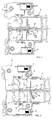
- the elastic means consists of a pair of spiral springs 7 (for clarity of description, in the figures only one spring 7 is visible) mounted inside the outer casing 5 (to which they are fixed in a manner known per se) in symmetrical positions with respect to the longitudinal axis of symmetry of the support 4.
- Figure 1 shows, schematically, a cross-section of the invention with the ends 3 (seen more clearly in Figures 2 to 4) of the fuse 1 fully inserted into the clamps 2; the free end of each of the springs 7 is located in a recess 8 (seen more clearly in Figures 2 to 4) made on the front surface of the projection 9 belonging to a longitudinal rib 10 of the support 4.
- the springs 7 are mounted in the outer casing 5 in such a way as to be inclined towards the clamps 2 when the fuse 1 is fully inserted into these clamps: under these conditions the forces exerted by the springs 7 tend to maintain the fuse 1 in its seat and ease the insertion thereof into the clamps 2, by reducing the force required from the operator.
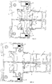
- Figure 2 shows, schematically, a cross-section of the invention in which the support 4, partially extracted from the outer casing 5 by the operator, has undergone a translation (of greater amplitude than the so-called “travel of disengagement” of the fuse 1 from the clamps 2) such as to unfasten the ends 3 of the fuse 1 from the clamps 2, which ends touch (or can touch) the clamps (to which they are in any event very close) but are no longer retained by the clamps 2; the distance between the clamps 2 and the ends 3 of the fuse 1 is in any event much less than the minimum safety distance prescribed by the Standards relating to disconnectors and, in a fuse-holder of known type, remains unchanged if for any reason the operator releases the support 4.
- a translation of greater amplitude than the so-called “travel of disengagement” of the fuse 1 from the clamps 2
- the distance between the clamps 2 and the ends 3 of the fuse 1 is in any event much less than the minimum safety distance prescribed by the Standards relating to disconnectors and, in a fuse-holder of known
- Figure 3 shows, schematically, a cross-section of the invention in which the action of the springs 7 has extracted the support 4 from the outer casing 5 so as to carry the ends 3 of the fuse 1 to a distance from the clamps 2 not less than the minimum safety distance prescribed by the aforesaid Standards: the springs 7 have accomplished their task and are (or could be) unloaded.
- the support 4 (released by the operator after having unfastened the fuse 1 from the clamps 2) is therefore positioned automatically in such a way as to satisfy the Standards relating to disconnectors.
- Figure 4 shows, schematically, a cross-section of the invention in which the operator has extracted the support 4 fully from the outer casing 5: as the support 4 passes from the position of Figure 3 to that of Figure 4, the free end of each of the springs 7 runs (almost) without friction in a seat 12 formed in the corresponding rib 10 of the support 4.
Landscapes
- Fuses (AREA)
Abstract
Description
- exhibiting two stable positions (disconnector closed or open);
- when the disconnector is open, a specified minimum safety distance must be guaranteed between its members.
- Figure 1 shows, schematically, a cross-section of the invention with the fuse fully inserted into the fixing means;
- Figure 2 shows, schematically, a cross-section of the invention with the fuse only just unfastened from the fixing means;
- Figures 3 shows, schematically, a cross-section of the invention with the fuse the safety distance away from the fixing means;
- Figure 4 shows, schematically, a cross-section of the invention with the support fully extracted.
- the
outer casing 5 consisting of two symmetric shells, preferably but not necessarily made from moulded plastic material, only one of which is visible in the appended figures; - the
support 4, which can move inside thecasing 5, and carries thefuse 1; - the fixing means, located inside the
casing 5, which consist, in the embodiment illustrated here, of a pair ofclamps 2 into which theends 3 of thefuse 1 are inserted; - the terminals 6 (each of which is electrically connected to one of the clamps 2) to which are adjoined the conductors which constitute the electric circuit to which the fuse-holder belongs; and
- elastic means, located inside the
casing 5 and acting on thesupport 4, which distance the fuse 1 (carried by the support 4) from theclamps 2 as soon as thefuse 1 is unfastened from theclamps 2, by carrying theends 3 of thefuse 1 to a distance from theclamps 2 not less than the minimum safety distance prescribed by the Standards relating to disconnectors.
Claims (8)
- Fuse-holder for switchboard, comprising at least one outer casing (5); a support (4), which can move inside the said outer casing (5) and is able to hold a fuse (1); fixing means (2), located inside the said outer casing (5), into which the ends (3) of the said fuse (1) are inserted and terminals (6) electrically connected to the said fixing means (2); characterized in that it furthermore comprises elastic means (7), located inside the said outer casing (5) and acting on the said support (4), which are able to distance the said fuse (1) from the said fixing means (2) as soon as the said fuse (1) is unfastened from the said fixing means (2) by acting on the said support (4), the action of the said elastic means (7) carrying the said ends (3) of the said fuse (1) to a distance from the said fixing means (2) not less than a specified minimum safety distance.
- Fuse-holder according to Claim 1, characterized in that the said fixing means (2) consist of a pair of clamp elements.
- Fuse-holder according to Claim 1, characterized in that the said elastic means (7) consist of a pair of spiral springs mounted inside the said outer casing (5) in symmetrical positions with respect to the longitudinal axis of symmetry of the said support (4).
- Fuse-holder according to Claim 3, characterized in that, when the said ends (3) of the said fuse (1) are fully inserted into the said fixing means (2), the free end of each of the said spiral springs (7) is located in a recess (8) made on the front surface of a projection (9) belonging to a longitudinal rib (10) of the said support (4).
- Fuse-holder according to Claim 3, characterized in that, when the said ends (3) of the said fuse (1) are fully inserted into the said fixing means (2), the said spiral springs (7) are inclined towards the said fixing means (2).
- Fuse-holder according to Claim 4, characterized in that, in response to a translation of the said support (4) of greater amplitude than the travel of disengagement of the said fuse (1) from the said fixing means (2), the said free end of each of the said spiral springs (7) is dislodged from the said recess (8) made on the said front surface of the said projection (9) belonging to the said longitudinal rib (10) of the said support (4) so as to rest against the flank (11) of the said projection (9), the distance of the said flank (11) of the said projection (9) from the centre of the said recess (8) being equivalent to the amplitude of the said translation of the said support (4) and in that the action of the said spiral springs (7) on the said flank (11) of the said projection (9) carries the said ends (3) of the said fuse (1) to a distance from the said fixing means (2) not less than the said specified minimum safety distance.
- Fuse-holder according to Claim 6, characterized in that, during the further translation of the said support performed by the operator so as to extract the said support (4) fully from the said outer casing (5), the said free end of each of the said spiral springs (7) runs in a seat (12) formed in the said rib (10) of the said support (4).
- Fuse-holder according to Claims 4 to 7, characterized in that, when the said support (4) has been fully extracted from the said outer casing (5) and the operator exerts a pressure on the said support (4) so as to insert the said ends (3) of the said fuse (1) into the said fixing means (2),the said free end of each of the said spiral springs (7) runs in the said seat (12) until it lodges against the said flank (11) of the said projection (9);the further translation of the said support (4) loads the said spiral spring (7);when the distance from the travel end of the said support (4) is not greater than the said travel of disengagement of the said fuse (1) from the said fixing means (2), the said free end of each of the said spiral springs (7) is carried onto the said front surface of the said projection (9), over which it runs until it is positioned in the said recess (8).
Applications Claiming Priority (2)
| Application Number | Priority Date | Filing Date | Title |
|---|---|---|---|
| ITMI962543 | 1996-12-04 | ||
| IT96MI002543A IT1286436B1 (en) | 1996-12-04 | 1996-12-04 | FUSE-HOLDER DISCONNECTOR FOR ELECTRICAL PANEL |
Publications (2)
| Publication Number | Publication Date |
|---|---|
| EP0852388A1 true EP0852388A1 (en) | 1998-07-08 |
| EP0852388B1 EP0852388B1 (en) | 2005-03-02 |
Family
ID=11375345
Family Applications (1)
| Application Number | Title | Priority Date | Filing Date |
|---|---|---|---|
| EP97203779A Expired - Lifetime EP0852388B1 (en) | 1996-12-04 | 1997-12-03 | Fuse-holder disconnector for switchboard |
Country Status (3)
| Country | Link |
|---|---|
| EP (1) | EP0852388B1 (en) |
| ES (1) | ES2238711T3 (en) |
| IT (1) | IT1286436B1 (en) |
Cited By (6)
| Publication number | Priority date | Publication date | Assignee | Title |
|---|---|---|---|---|
| WO2000063940A1 (en) * | 1999-04-20 | 2000-10-26 | Felten & Guilleaume Kg | Fuse switch |
| EP1032005A3 (en) * | 1999-02-23 | 2002-04-24 | CEAG Sicherheitstechnik GmbH | Electrical installation |
| GB2339091B (en) * | 1998-05-05 | 2002-10-09 | Cooper Technologies Co | Pull-out high current switch |
| EP2242082A1 (en) * | 2009-04-14 | 2010-10-20 | Wöhner GmbH & Co. KG Elektrotechnische Systeme | Holder for fuses |
| FR2982705A1 (en) * | 2011-11-16 | 2013-05-17 | Ece | DEVICE FOR PROTECTING AN ELECTRICAL CIRCUIT POWERED BY AN INTEGRABLE ALTERNATING CURRENT IN A CONTACTOR. |
| US9613776B2 (en) | 2014-08-19 | 2017-04-04 | Regal Beloit America, Inc. | Fuse holder and associated method |
Citations (6)
| Publication number | Priority date | Publication date | Assignee | Title |
|---|---|---|---|---|
| GB581048A (en) * | 1944-08-04 | 1946-09-30 | Vernon Hope | Improvements in or relating to push pull switch-fuses |
| US2842640A (en) * | 1955-12-13 | 1958-07-08 | Robert S Ragan | Cam-actuated, quick break electric switch |
| DE1178131B (en) * | 1959-10-15 | 1964-09-17 | Telemecanique Electrique | Disconnector with fuse cartridges |
| EP0067914A1 (en) * | 1981-04-29 | 1982-12-29 | Chang Chien Chen | Fuse unit |
| DE3303471A1 (en) * | 1983-02-02 | 1984-08-02 | Siemens AG, 1000 Berlin und 8000 München | ROW TERMINAL |
| DE8716273U1 (en) * | 1987-12-09 | 1988-02-18 | Klaus Bruchmann GmbH, 96450 Coburg | Circuit breaker |
-
1996
- 1996-12-04 IT IT96MI002543A patent/IT1286436B1/en active IP Right Grant
-
1997
- 1997-12-03 EP EP97203779A patent/EP0852388B1/en not_active Expired - Lifetime
- 1997-12-03 ES ES97203779T patent/ES2238711T3/en not_active Expired - Lifetime
Patent Citations (6)
| Publication number | Priority date | Publication date | Assignee | Title |
|---|---|---|---|---|
| GB581048A (en) * | 1944-08-04 | 1946-09-30 | Vernon Hope | Improvements in or relating to push pull switch-fuses |
| US2842640A (en) * | 1955-12-13 | 1958-07-08 | Robert S Ragan | Cam-actuated, quick break electric switch |
| DE1178131B (en) * | 1959-10-15 | 1964-09-17 | Telemecanique Electrique | Disconnector with fuse cartridges |
| EP0067914A1 (en) * | 1981-04-29 | 1982-12-29 | Chang Chien Chen | Fuse unit |
| DE3303471A1 (en) * | 1983-02-02 | 1984-08-02 | Siemens AG, 1000 Berlin und 8000 München | ROW TERMINAL |
| DE8716273U1 (en) * | 1987-12-09 | 1988-02-18 | Klaus Bruchmann GmbH, 96450 Coburg | Circuit breaker |
Cited By (13)
| Publication number | Priority date | Publication date | Assignee | Title |
|---|---|---|---|---|
| GB2339091B (en) * | 1998-05-05 | 2002-10-09 | Cooper Technologies Co | Pull-out high current switch |
| EP1032005A3 (en) * | 1999-02-23 | 2002-04-24 | CEAG Sicherheitstechnik GmbH | Electrical installation |
| WO2000063940A1 (en) * | 1999-04-20 | 2000-10-26 | Felten & Guilleaume Kg | Fuse switch |
| AU762695B2 (en) * | 1999-04-20 | 2003-07-03 | Moeller Gebaudeautomation Kg | Fuse switch |
| CZ302064B6 (en) * | 1999-04-20 | 2010-09-22 | Moeller Gebäudeautomation KG | Switch with fusible cut-out |
| US8384509B2 (en) | 2009-04-14 | 2013-02-26 | Woehner Gmbh & Co., Kg Elektrotechnische Systeme | Holder for fuses |
| EP2242082A1 (en) * | 2009-04-14 | 2010-10-20 | Wöhner GmbH & Co. KG Elektrotechnische Systeme | Holder for fuses |
| FR2982705A1 (en) * | 2011-11-16 | 2013-05-17 | Ece | DEVICE FOR PROTECTING AN ELECTRICAL CIRCUIT POWERED BY AN INTEGRABLE ALTERNATING CURRENT IN A CONTACTOR. |
| CN103117198A (en) * | 2011-11-16 | 2013-05-22 | Ece公司 | Device for protecting an electric circuit supplied by alternating current, which can be integrated into a contactor |
| US9773625B2 (en) | 2011-11-16 | 2017-09-26 | Ece | Device for protecting an electrical circuit fed by an alternating current which can be integrated into a contactor |
| US9613776B2 (en) | 2014-08-19 | 2017-04-04 | Regal Beloit America, Inc. | Fuse holder and associated method |
| US10049846B2 (en) | 2014-08-19 | 2018-08-14 | Regal Beloit America, Inc. | Fuse holder and associated method |
| US10886089B2 (en) | 2014-08-19 | 2021-01-05 | Regal Beloit America, Inc. | Fuse holder and associated method |
Also Published As
| Publication number | Publication date |
|---|---|
| ES2238711T3 (en) | 2005-09-01 |
| EP0852388B1 (en) | 2005-03-02 |
| ITMI962543A0 (en) | 1996-12-04 |
| ITMI962543A1 (en) | 1998-06-04 |
| IT1286436B1 (en) | 1998-07-08 |
Similar Documents
| Publication | Publication Date | Title |
|---|---|---|
| AU598745B2 (en) | Circuit breaker with blow open latch | |
| CA2781263C (en) | Disconnect switch including fusible switching disconnect modules | |
| US10665413B2 (en) | Fusible switch disconnect device for DC electrical power system | |
| US2916675A (en) | Means for preventing interchangeability of circuit breakers of similar construction but different capacity | |
| EP1442467B1 (en) | Low-voltage circuit breaker | |
| CN104919562A (en) | Circuit breaker and adapter for a circuit breaker | |
| EP0852388B1 (en) | Fuse-holder disconnector for switchboard | |
| MXPA01011432A (en) | Circuit breaker latch mechanism with decreased trip time. | |
| AU606369B2 (en) | Circuit breaker with magnetic shunt hold back circuit | |
| US2844689A (en) | Circuit breaker | |
| US3009035A (en) | Circuit interrupters | |
| GB1603996A (en) | Adjustable trip unit for electrical circuit interrupters | |
| US3009036A (en) | Circuit interrupter | |
| PL183078B1 (en) | Safety disconnect switch | |
| US3009037A (en) | Current limiting circuit breaker | |
| EP2667398B1 (en) | Residual current operated circuit breaker with self-test device | |
| US4181906A (en) | Circuit interrupter with interlocked removable trip unit | |
| US3781607A (en) | Device for removably mounting electrical component | |
| AU2005313826B2 (en) | Master breaker device for back-up protection against electric shock in earthed user units with mains voltage dependent residual current triggering and high selectivity | |
| EP4356412A1 (en) | Circuit breaker | |
| CN214898296U (en) | Small-size residual current circuit breaker electric leakage indicating device | |
| GB2169749A (en) | Electrical outlet accessories with incorporated automatic circuit breaker | |
| CA2245300C (en) | Fusible element | |
| EP1234317A1 (en) | An improved low-voltage power circuit breaker | |
| CA1129914A (en) | Fuse with low current trip mechanism |
Legal Events
| Date | Code | Title | Description |
|---|---|---|---|
| PUAI | Public reference made under article 153(3) epc to a published international application that has entered the european phase |
Free format text: ORIGINAL CODE: 0009012 |
|
| AK | Designated contracting states |
Kind code of ref document: A1 Designated state(s): ES FR IT PT |
|
| AX | Request for extension of the european patent |
Free format text: AL;LT;LV;MK;RO;SI |
|
| 17P | Request for examination filed |
Effective date: 19981222 |
|
| AKX | Designation fees paid |
Free format text: ES FR IT PT |
|
| RBV | Designated contracting states (corrected) |
Designated state(s): ES FR IT PT |
|
| REG | Reference to a national code |
Ref country code: DE Ref legal event code: 8566 |
|
| 17Q | First examination report despatched |
Effective date: 20030908 |
|
| GRAP | Despatch of communication of intention to grant a patent |
Free format text: ORIGINAL CODE: EPIDOSNIGR1 |
|
| GRAS | Grant fee paid |
Free format text: ORIGINAL CODE: EPIDOSNIGR3 |
|
| GRAA | (expected) grant |
Free format text: ORIGINAL CODE: 0009210 |
|
| RAP1 | Party data changed (applicant data changed or rights of an application transferred) |
Owner name: ABB SACE S.P.A. |
|
| AK | Designated contracting states |
Kind code of ref document: B1 Designated state(s): ES FR IT PT |
|
| PG25 | Lapsed in a contracting state [announced via postgrant information from national office to epo] |
Ref country code: PT Free format text: LAPSE BECAUSE OF FAILURE TO SUBMIT A TRANSLATION OF THE DESCRIPTION OR TO PAY THE FEE WITHIN THE PRESCRIBED TIME-LIMIT Effective date: 20050817 |
|
| REG | Reference to a national code |
Ref country code: ES Ref legal event code: FG2A Ref document number: 2238711 Country of ref document: ES Kind code of ref document: T3 |
|
| PLBE | No opposition filed within time limit |
Free format text: ORIGINAL CODE: 0009261 |
|
| STAA | Information on the status of an ep patent application or granted ep patent |
Free format text: STATUS: NO OPPOSITION FILED WITHIN TIME LIMIT |
|
| 26N | No opposition filed |
Effective date: 20051205 |
|
| ET | Fr: translation filed | ||
| REG | Reference to a national code |
Ref country code: FR Ref legal event code: TP |
|
| PGFP | Annual fee paid to national office [announced via postgrant information from national office to epo] |
Ref country code: IT Payment date: 20121227 Year of fee payment: 16 |
|
| PGFP | Annual fee paid to national office [announced via postgrant information from national office to epo] |
Ref country code: ES Payment date: 20121226 Year of fee payment: 16 Ref country code: FR Payment date: 20130130 Year of fee payment: 16 |
|
| REG | Reference to a national code |
Ref country code: FR Ref legal event code: ST Effective date: 20140829 |
|
| PG25 | Lapsed in a contracting state [announced via postgrant information from national office to epo] |
Ref country code: FR Free format text: LAPSE BECAUSE OF NON-PAYMENT OF DUE FEES Effective date: 20131231 |
|
| REG | Reference to a national code |
Ref country code: ES Ref legal event code: FD2A Effective date: 20150407 |
|
| PG25 | Lapsed in a contracting state [announced via postgrant information from national office to epo] |
Ref country code: ES Free format text: LAPSE BECAUSE OF NON-PAYMENT OF DUE FEES Effective date: 20131204 |
|
| PG25 | Lapsed in a contracting state [announced via postgrant information from national office to epo] |
Ref country code: IT Free format text: LAPSE BECAUSE OF NON-PAYMENT OF DUE FEES Effective date: 20131231 |
|
| PG25 | Lapsed in a contracting state [announced via postgrant information from national office to epo] |
Ref country code: IT Free format text: LAPSE BECAUSE OF NON-PAYMENT OF DUE FEES Effective date: 20131203 |