EP2631696A2 - Bilderzeuger - Google Patents
Bilderzeuger Download PDFInfo
- Publication number
- EP2631696A2 EP2631696A2 EP12186772.5A EP12186772A EP2631696A2 EP 2631696 A2 EP2631696 A2 EP 2631696A2 EP 12186772 A EP12186772 A EP 12186772A EP 2631696 A2 EP2631696 A2 EP 2631696A2
- Authority
- EP
- European Patent Office
- Prior art keywords
- image
- dimensional object
- grounding plane
- overhead view
- grounding
- Prior art date
- Legal status (The legal status is an assumption and is not a legal conclusion. Google has not performed a legal analysis and makes no representation as to the accuracy of the status listed.)
- Granted
Links
Images


Classifications
-
- G—PHYSICS
- G06—COMPUTING; CALCULATING OR COUNTING
- G06T—IMAGE DATA PROCESSING OR GENERATION, IN GENERAL
- G06T15/00—3D [Three Dimensional] image rendering
- G06T15/10—Geometric effects
- G06T15/20—Perspective computation
-
- G—PHYSICS
- G06—COMPUTING; CALCULATING OR COUNTING
- G06T—IMAGE DATA PROCESSING OR GENERATION, IN GENERAL
- G06T7/00—Image analysis
- G06T7/70—Determining position or orientation of objects or cameras
-
- G—PHYSICS
- G06—COMPUTING; CALCULATING OR COUNTING
- G06V—IMAGE OR VIDEO RECOGNITION OR UNDERSTANDING
- G06V20/00—Scenes; Scene-specific elements
- G06V20/50—Context or environment of the image
- G06V20/56—Context or environment of the image exterior to a vehicle by using sensors mounted on the vehicle
- G06V20/58—Recognition of moving objects or obstacles, e.g. vehicles or pedestrians; Recognition of traffic objects, e.g. traffic signs, traffic lights or roads
-
- G—PHYSICS
- G08—SIGNALLING
- G08G—TRAFFIC CONTROL SYSTEMS
- G08G1/00—Traffic control systems for road vehicles
- G08G1/16—Anti-collision systems
- G08G1/165—Anti-collision systems for passive traffic, e.g. including static obstacles, trees
-
- G—PHYSICS
- G08—SIGNALLING
- G08G—TRAFFIC CONTROL SYSTEMS
- G08G1/00—Traffic control systems for road vehicles
- G08G1/16—Anti-collision systems
- G08G1/166—Anti-collision systems for active traffic, e.g. moving vehicles, pedestrians, bikes
-
- G—PHYSICS
- G08—SIGNALLING
- G08G—TRAFFIC CONTROL SYSTEMS
- G08G1/00—Traffic control systems for road vehicles
- G08G1/16—Anti-collision systems
- G08G1/168—Driving aids for parking, e.g. acoustic or visual feedback on parking space
-
- G—PHYSICS
- G06—COMPUTING; CALCULATING OR COUNTING
- G06T—IMAGE DATA PROCESSING OR GENERATION, IN GENERAL
- G06T2207/00—Indexing scheme for image analysis or image enhancement
- G06T2207/10—Image acquisition modality
- G06T2207/10004—Still image; Photographic image
- G06T2207/10012—Stereo images
-
- G—PHYSICS
- G06—COMPUTING; CALCULATING OR COUNTING
- G06T—IMAGE DATA PROCESSING OR GENERATION, IN GENERAL
- G06T2207/00—Indexing scheme for image analysis or image enhancement
- G06T2207/30—Subject of image; Context of image processing
- G06T2207/30248—Vehicle exterior or interior
- G06T2207/30252—Vehicle exterior; Vicinity of vehicle
- G06T2207/30261—Obstacle
Definitions
- This disclosure relates to an image generator for outputting an overhead view image as monitor display image, the overhead view image being generated by performing a projective transformation, with a virtual viewpoint above a vehicle, of an image captured by an on-board camera for capturing an image of a surrounding region of the vehicle.
- an overhead view image from directly above a vehicle is generated using an image transformation principle in which an image captured by an on-board camera is projected on a projection plane in parallel with a road surface, in other words, using a projective transformation in which a virtual viewpoint is positioned vertically above the vehicle.
- a driver is allowed to grasp a road surface state around the vehicle in a bird's-eye way.
- a three-dimensional object standing on the road surface is elongated in an image capturing direction of the camera, and thus it becomes difficult for the driver to grasp a shape of the actual three-dimensional object from the overhead view image.
- the overhead view image that covers the entire surroundings of the vehicle is generated from the captured images of a plurality of the on-board cameras, image composition of common regions in the adjacent captured images, i.e. overlap regions, has been generally performed.
- the image capturing directions of the respective original captured images of the overlap regions differ to a large extent, and the three-dimensional object present in the overlap region is elongated in two directions.
- the three-dimensional object appears as two three-dimensional object images in deformed shapes, and it becomes difficult to recognize the three-dimensional object, especially a standing position thereof, making a sense of a distance between the vehicle and the three-dimensional object ambiguous.
- Japanese Unexamined Patent Application Publication No. 2010-251939 proposed a vehicle surroundings image display system including: a camera for capturing an image of vehicle surroundings; an obstacle detection means for detecting an obstacle in the vehicle surroundings; a memory section for storing in advance a substitute image corresponding to the obstacle; and an image processing section for generating the overhead view image of the vehicle surroundings from the virtual viewpoint based on the image captured by the camera, wherein, when the obstacle detection means detects the obstacle (three-dimensional object), the image processing section identifies the obstacle, selects a substitute image corresponding to the identified obstacle, reads the selected substitute image from the memory section, adjusts a direction and an inclination of the selected substitute image in accordance with the virtual viewpoint, and superimposes the adjusted image on the overhead view image.
- the image processing section transforms the image captured by an imaging means into the overhead view image from above the vehicle or from a side of the vehicle, and based on information from the obstacle detection means, the image processing section selects the substitute image from the memory section which is consistent with a size and movement of the obstacle present in the vehicle surroundings, and superimposes the selected image on the same overhead view image.
- the image generator in accordance with one or more embodiments includes: an overhead view image generation section for generating an overhead view image by performing a projective transformation, with a virtual viewpoint above a vehicle, of an image captured by an on-board camera for capturing an image of a surrounding region of the vehicle; a three-dimensional object detection section for recognizing a three-dimensional object present in the surrounding region and outputting three-dimensional object attribute information showing an attribute of the three-dimensional object; and an image composition section for generating a monitor display image for vehicle driving assistance by performing image composition of a grounding plane mark showing a grounding location of the three-dimensional object with a portion at the grounding location in the overhead view image, based on the three-dimensional object attribute information.
- the attribute of the three-dimensional object means location, posture, size, type, color or the like of the three-dimensional object present in field of view of the on-board camera, and an attribute value of the three-dimensional object showing this attribute is contained in the three-dimensional object attribute information.
- the overhead view image in which the grounding plane mark is additionally drawn at the grounding location as standing position of the three-dimensional object is generated as monitor display image, and therefore, even though the three-dimensional object is shown with a deformed shape which is elongated in the image-capturing direction, a driver is allowed to clearly grasp the grounding location of the three-dimensional object by means of the grounding plane mark.
- a grounding plane of the three-dimensional object as a common region in the three-dimensional object image is shown with the grounding plane mark. Therefore, even in such a case, the driver can grasp the standing position of the three-dimensional object by means of the monitor display image.
- the grounding plane mark is in a flattened shape, preferably in a shape of an ellipse, and an inclined posture of the grounding plane mark is determined so that a line of direction from the vehicle to the three-dimensional object becomes orthogonal to a major axis of the ellipse.
- the grounding plane mark By making the grounding plane mark in a flattened shape, and by setting an arrangement posture of the grounding location of the three-dimensional object so as to become orthogonal to the line of direction from the vehicle (for example, a vehicle center or an on-board camera center) to the three-dimensional object, the driver can grasp the direction in which the three-dimensional object is present relative to the vehicle, from the inclined posture of the grounding plane mark.
- the grounding plane mark is in a shape of an ellipse, a contour has a smooth edge and thus an edge obtained after image composition becomes smooth and easily viewable.
- a grounding plane size of the three-dimensional object in the overhead view image varies depending on a distance from the vehicle or a type of the three-dimensional object. Therefore, in one preferred embodiment of this disclosure, it is convenient that a size of the grounding plane mark is determined in accordance with the three-dimensional object attribute information. In another preferred embodiment of this disclosure, it is convenient that a size of the grounding plane mark is set larger than a width of the three-dimensional object in the overhead view image, based on a width of the three-dimensional object contained in the three-dimensional object attribute information.
- a three-dimensional object image layer containing the three-dimensional object alone is generated from a basic image layer containing the overhead view image
- the grounding plane mark is placed between the basic image layer and the three-dimensional object image layer, and at the same time, positioned at the grounding location of the three-dimensional object in the overhead view image.
- the grounding plane mark is pasted as a background of the three-dimensional object in the overhead view image, a sense of depth is given to the three-dimensional object, making the three-dimensional object and the grounding plane mark more visible.
- the grounding plane mark shows the grounding plane of the three-dimensional object.
- the grounding plane mark is superimposed on the grounding location of the three-dimensional object in the overhead view image.
- the grounding plane mark is simply pasted at the grounding location of the three-dimensional object in the overhead view image, and thus the image composition can be achieved with a simple image processing.
- the overhead view image generation section includes a grounding plane mark storing section for storing a plurality of the grounding plane marks; and a grounding plane mark output section for extracting an appropriate grounding plane mark from the grounding plane mark storing section based on the three-dimensional object attribute information, and sending the selected grounding plane mark to the image composition section.
- a grounding plane mark storing section for storing a plurality of the grounding plane marks
- a grounding plane mark output section for extracting an appropriate grounding plane mark from the grounding plane mark storing section based on the three-dimensional object attribute information, and sending the selected grounding plane mark to the image composition section.
- an indication of a distance from the grounding location of the three-dimensional object to the vehicle is added in the vicinity of the grounding plane mark.
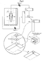
- Fig. 1 is a schematic drawing explaining a basic concept of this disclosure for arranging a grounding plane mark at a grounding location of a three-dimensional object in an overhead view image.
- Fig. 2 is a schematic drawing explaining image composition of the overhead view image with the grounding plane mark in a three-dimensional object region.
- Fig. 3 is a functional block diagram of a vehicle surroundings monitoring system to which an image generator according to this disclosure is applied.
- Fig. 4 is a functional block diagram of an image processing module forming the vehicle surroundings monitoring system.
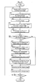
- Fig. 5 is a flow chart showing a routine of displaying the overhead view image.
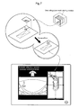
- Fig. 6 is a schematic drawing illustrating generation and display of the overhead view image with the grounding plane mark.
- Fig. 7 is a schematic drawing illustrating generation and display of the overhead view image with the grounding plane mark according to another embodiment.
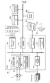
- Fig. 8 is a functional block diagram of the vehicle surroundings monitoring system to which an image generator according to another embodiment is applied.
- a basic concept of this disclosure will be described with reference to a schematic drawing of Fig. 1 .
- cameras 1a - 1d are mounted on front, left, right and rear sides of the vehicle.
- images of surrounding regions of the own vehicle are captured by the cameras (#1).
- the captured images are used also in a detection processing of a three-dimensional object as obstacle around the vehicle.
- the three-dimensional object to be processed is a cylindrical object placed on a front left side of the vehicle. The cylindrical object appears in both a front captured image and a left captured image.
- the three-dimensional object is recognized by, for example: determining whether the object is a dynamic body or a stationary body with using motion vector method or difference method; specifying a shape by size measurement or edge detection; and identifying a type of the object based on color information (#2).
- the three-dimensional object may be recognized in more detail through image recognition using the captured image, based on the sensing information after sensing the three-dimensional object with using ultrasonic wave, laser radar or the like.
- image recognition there are generated three-dimensional object attribute information containing attribute values of the three-dimensional object, such as location, posture, size, type and color of the three-dimensional object present in field of view of the on-board camera (#3).
- a projective transformation in which a projection plane is in parallel with the road surface is performed, that is, the projective transformation is performed using a mapping in which a viewpoint transformation where a virtual viewpoint is set directly above the vehicle is set in advance (#4).
- the projective transformation is performed using a mapping in which a viewpoint transformation where a virtual viewpoint is set directly above the vehicle is set in advance (#4).
- a three-dimensional object region in the overhead view image of the detected three-dimensional object is clipped from the overhead view image, based on the three-dimensional object attribute information (#6).
- a grounding plane mark showing a grounding plane of the three-dimensional object which mark is suitable for the three-dimensional object detected based on the three-dimensional object attribute information is extracted from a grounding plane mark storing section.
- the grounding plane mark may be created every time (#7).
- Image composition of all the overhead view image from which the three-dimensional object region was clipped, the clipped three-dimensional object region, and the extracted grounding plane mark is performed, as shown in Fig. 2 , in a layer composition order of: the overhead view image from which the three-dimensional object region was clipped (rearmost layer), the grounding plane mark (back layer), and the clipped three-dimensional object region (front layer) (#8).
- the grounding plane mark shows the grounding plane of the three-dimensional object.
- the grounding plane mark may be directly superimposed on the overhead view image containing the three-dimensional object region.
- the image generated by the image composition is transmitted as monitor display image to the monitor, and displayed on a monitor screen together with one or more captured images selected as needed (#9).
- FIG. 3 is a functional block diagram showing a control system forming a vehicle surroundings monitoring system to which an image generator according to the embodiment is applied.
- the vehicle having the vehicle surroundings monitoring system mounted thereon is provided with four on-board cameras 1, specifically, the front camera 1a, the rear camera 1d, the left side camera 1b, and the right side camera 1c.
- An omni-directional overhead view image is created from the images captured by the on-board cameras 1.
- the on-board cameras 1a, 1b, 1c, 1d may be collectively referred to as "camera 1".
- the camera 1 is a digital camera for capturing images of the vehicle surroundings sequentially at intervals, digitally transforming the captured image and outputting the digitally transformed image in real time.
- the camera 1 is provided with ether a wide-angle lens or a fisheye lens.
- An ECU 20 that forms a core component of the vehicle surroundings monitoring system includes, as shown in Fig. 3 , a sensor input interface 23 or a communication interface 70 for transmitting signal inputs from a group of vehicle state detection sensors, as-is or after evaluated them, to an inside of the ECU 20; a microprocessor for processing input information; a DSP; and the like.
- a group of the vehicle state detection sensors connected to the sensor input interface 23 are configured to detect conditions of drive operation or vehicle running.
- a group of the vehicle state detection sensors includes: a steering sensor for detecting a steering operation direction (steering direction) and measuring an operational amount (steering amount); a shift position sensor for detecting a shift position of a shift lever; an accelerator sensor for measuring an operational amount of an accelerator pedal; a brake sensor for detecting an operational amount of a brake pedal; and a distance sensor for detecting a travel distance of the own vehicle.
- an in-vehicle LAN can be adopted as data transmission line, to which control units, such as a monitor 21, a touch panel 21T, a power steering unit PS, a transmission mechanism T, and a braking device BK, are connected in a data-transmissive manner.
- control units such as a monitor 21, a touch panel 21T, a power steering unit PS, a transmission mechanism T, and a braking device BK, are connected in a data-transmissive manner.
- a speaker 22 is also provided as device for outputting audio information.
- the ECU 20 includes various functional sections formed of hardware and/or software, and the functional sections especially related to the embodiment include: an image processing module 50; a display control section 71; and an audio processing module 72.
- the monitor display image generated in the image processing module 50 is converted into a video signal in the display control section 71 and sent to the monitor 21.
- An audio guide, an emergency warning sound or the like generated in the audio processing module 72 is played by the speaker 22.
- Fig. 4 shows a functional block diagram of the image processing module 50 of the ECU 20.
- the image processing module 50 has a function of generating an image, such as the overhead view image, by the projective transformation from the image captured by the camera 1 for capturing an image around the own vehicle.
- the image processing module 50 includes a captured image memory 51, a preprocessing section 52, an image generation section 53, a three-dimensional object detection section 54, an image composition section 55, and a frame memory 56.
- the image captured by the camera 1 is loaded into the captured image memory 51, and the preprocessing section 52 adjusts luminance balance, color balance and the like between the images separately captured by the cameras 1.
- the three-dimensional object detection section 54 is configured to detect the three-dimensional object contained in the captured image by using an object image recognition algorithm which is well-known.
- the three-dimensional object attribute information of the detected three-dimensional object such as location, size, color, and posture of the three-dimensional object, is sent to the image generation section 53.
- the image generation section 53 includes a normal image generation section 60, an overhead view image generation section 61, a mapping table 62, a three-dimensional object clipping section 63, and a grounding plane mark output section 64.
- the normal image generation section 60 is configured to adjust the captured image to have an appropriate image quality to be displayed directly on the monitor as a vehicle surroundings image.
- the vehicle surroundings image displayed on the monitor may be a single image selected by the driver from the images captured by the front camera 1a, the left side camera 1b, the right side camera 1c, and the rear camera 1d, or may be a combination of a plurality of the captured images.
- the overhead view image generation section 61 has a function of generating the overhead view image by performing the projective transformation, with the virtual viewpoint above the vehicle, of a single or a plurality of the captured image loaded into the captured image memory 51, specifically, generating the overhead view image by a map transformation using the mapping table 62.
- the mapping table 62 various maps for the projective transformation used herein are stored in advance in a selectable manner.
- Each map stored in the mapping table 62 may be formed in various forms, and in this embodiment, formed as a map including a correspondence relationship between pixel data of the captured image and pixel data of a projective transformation image (in general the overhead view image).
- each pixel of the captured image of a single frame has been described with a destination pixel coordinate in the overhead view image, and a suitable map is applied to each of the on-board cameras.
- the overhead view image generation section 61 has a function of selecting a suitable map from the mapping table 62, based on an external command or an internal command.
- a composition technique is applied in which a composition is performed so that the grounding plane mark is arranged on a back side of the three-dimensional object image region, in order not to make the grounding plane mark conceal a three-dimensional object image region in the overhead view image where the three-dimensional object detected by the three-dimensional object detection section 54 is present.
- the three-dimensional object clipping section 63 clips the three-dimensional object image region from the overhead view image, based on the three-dimensional object attribute information sent from the three-dimensional object detection section 54.
- the clipped three-dimensional object image and the overhead view image are transmitted to the image composition section 55.
- the grounding plane mark output section 64 has a function of outputting, to the image composition section 55, the grounding plane mark which is suitable for showing a grounding location of the three-dimensional object based on the three-dimensional object attribute information sent from the three-dimensional object detection section 54, when the three-dimensional object is detected by the three-dimensional object detection section 54.
- the grounding plane mark output section 64 includes: a grounding plane center calculation section 64a; a grounding plane size calculation section 64b; a grounding plane inclination calculation section 64c; and a grounding plane mark storing section 64d.
- the grounding plane mark output by the grounding plane mark output section 64 is in a shape of an ellipse. It is preferable that a ratio of a major axis to a minor axis thereof is approximately 2.5 to 1, but this ratio varies depending on a shape of a display region of the overhead view image allotted on the monitor.
- the grounding plane center calculation section 64a is configured to calculate a grounding plane center position of the three-dimensional object in the overhead view image, based on the location of the three-dimensional object contained in the three-dimensional object attribute information.
- the grounding plane size calculation section 64b is configured to calculate a size of the grounding plane mark based on a width of the three-dimensional object seen from the own vehicle contained in the three-dimensional object attribute information so that the major axis of the grounding plane mark becomes larger than such a width in the overhead view image.
- the grounding plane inclination calculation section 64c is configured to calculate an inclination angle (posture) of the grounding plane mark at which the major axis of the grounding plane mark becomes orthogonal to a straight line connecting the grounding plane center position of the three-dimensional object calculated by the grounding plane center calculation section 64a and a vehicle center.
- the grounding plane mark storing section 64d is configured to store image data of the grounding plane mark having a size and a posture that can be calculated by the grounding plane size calculation section 64b and the grounding plane inclination calculation section 64c, respectively.
- the grounding plane mark storing section 64d can store a plurality of the grounding plane marks.
- the grounding plane mark output section 64 is configured to extract the suitable grounding plane mark (image data) from the grounding plane mark storing section 64d, and output the extracted grounding plane mark to the image composition section 55, together with data of the grounding plane center position calculated by the grounding plane center calculation section 64a.
- grounding plane mark storing section 64d storing in advance all of the potentially usable grounding plane marks (image data)
- a basic image may be stored from which a desired grounding plane mark is generated.
- a generation algorithm of the grounding plane mark (image data) may be stored and the grounding plane mark having the size and the posture calculated by the grounding plane size calculation section 64b and the grounding plane inclination calculation section 64c, respectively, may be created every time.
- the grounding plane size calculation section 64b can be omitted.
- the image composition section 55 is configured to superimpose an illustration or picture of the own vehicle at a center of the omni-directional overhead view image of the vehicle generated in the overhead view image generation section 61, when the three-dimensional object detection section 54 does not detect the three-dimensional object.
- the image composition section 55 receives the overhead view image and the three-dimensional object image clipped from the overhead view image, sent from the three-dimensional object clipping section 63, as well as the grounding plane mark and arrangement data of the grounding plane mark (data of the grounding plane center position), sent from the grounding plane mark output section 64.
- the image composition section 55 is configured to perform a layer composition in which the overhead view image from which the three-dimensional object region was clipped is placed on a rearmost layer, the grounding plane mark is placed on a back layer, and the clipped three-dimensional object region is placed on a front layer, to thereby generate the overhead view image in which the grounding plane mark in an ellipsoidal shape is added to the grounding plane of the three-dimensional object.
- the generated overhead view image is put into a predetermined template, and transmitted as monitor display image for vehicle driving assistance to the frame memory 56.
- the monitor display image transmitted to the frame memory 56 is displayed on the monitor 21 through the display control section 71.
- a display mode of the overhead view image is read which is set manually in accordance with the driver's preference or set by default (#01).
- the display mode of the overhead view image means items that defines the captured image and the position of the virtual viewpoint which are used when the overhead view image around the vehicle is generated, and items that defines the layout of the generated overhead view image on the monitor screen.
- a map for the projective transformation used in the overhead view image generation section 61 in accordance with the display mode of the overhead view image read in is set for every captured image of the on-board camera 1 to be used (#02).
- the images are captured by the four on-board cameras 1 (#03).
- An overhead view image segment is generated from each of the captured images using each set map (#04).
- the generated overhead view image segments are combined and the omni-directional overhead view image around the vehicle is generated (#05).
- the overhead view image (picture, illustration, symbol or the like) of the vehicle which is set in advance is arranged at a location of the own vehicle in the overhead view image generated at the step #05, and the overhead view image (monitor display image) to be displayed on the monitor is generated (#20).
- the generated monitor display image is displayed on the monitor 21 (#21). Unless there is an instruction to finish the routine of displaying the overhead view image, the procedure goes back to the step #01 ("No" branch at #22) and the routine will be repeated.
- the three-dimensional object clipping section 63 clips the three-dimensional object image region from the overhead view image (#09), and the grounding plane mark output section 64 outputs the grounding plane mark suitable for the three-dimensional object of interest (#10).
- the image composition section 55 the overhead view image in which the grounding plane mark in an ellipsoidal shape is added to the grounding plane of the three-dimensional object is generated (#11).
- the overhead view image with the grounding plane mark is generated as monitor display image (#20), and the generated monitor display image is displayed on the monitor 21 (#21).
- the overhead view image with the grounding plane mark is arranged side by side with a front camera captured image in which the three-dimensional object (herein pedestrian) is captured.
- the image obtained from the captured image through the projective transformation utilizing a viewpoint above the vehicle and the projecting plane in parallel with the road surface is used as the overhead view image.
- the embodiment is not limited to the overhead view image obtained through such a projective transformation.
- the overhead view image may be obtained using a concave curved face or a flexed curved face as projecting plane.
- the grounding plane mark is superimposed in the overhead view image in such a manner that the ground plane mark becomes a background of the three-dimensional object.
- image composition can be used in which the grounding plane mark is simply superimposed at the grounding location of the three-dimensional object in the overhead view image.
- the distance (minimum distance is preferable) from the own vehicle can be obtained.
- the distance thereof may be obtained from the captured image.
- the distance between the detected three-dimensional object and the vehicle is obtained, and thus this distance can be contained in the monitor display image as distance from the grounding location of the three-dimensional object to the vehicle. For example, as shown in Fig. 7 , when the distance is displayed in the vicinity of the grounding plane mark, the driver can understand the accurate distance from the three-dimensional object.
- the three-dimensional object detection section 54 is configured to generate the three-dimensional object attribute information, by detecting the three-dimensional object from the captured image using an image recognition technique, and thus incorporated into the image processing module 50.
- the three-dimensional object detection section may be provided separately from the image processing module 50.
- a three-dimensional object recognition module 30 connected to the image processing module 50 through an in-vehicle communication pathway.
- the three-dimensional object recognition module 30 has a three-dimensional object sensing section 31 for evaluating detection signals from a plurality of ultrasonic sensors 3 to sense the three-dimensional object, and a three-dimension object recognition section 32 for recognizing the three-dimensional object contained in the image captured by the camera 1.
- the ultrasonic sensors 3 are provided at both end positions and an intermediate position in each of a front part, a rear part, a left part and a right part of the vehicle, and the object (obstacle) present in the vicinity of the vehicle surroundings can be sensed through the waves reflected therefrom.
- the distance from the vehicle to the object and the size of the object can be estimated, and further, by processing the detection results of all of the ultrasonic sensors 3 over time, a movement of the object or an outer shape in a transversal direction can be estimated.
- the three-dimensional object detection section 54 provided in the image processing module 50 simply has a function of receiving the three-dimensional object attribute information sent from the three-dimensional object recognition module 30.
- the ultrasonic sensor 3 laser radar or infrared may be used.
- the three-dimensional object detection section 54 detects the three-dimensional object by the image recognition technique, based on three-dimensional object location information from the image processing module 50.
- the embodiments are applicable to any system which monitors the surroundings of the vehicle using the overhead view image.
Landscapes
- Engineering & Computer Science (AREA)
- Physics & Mathematics (AREA)
- General Physics & Mathematics (AREA)
- Theoretical Computer Science (AREA)
- Computer Vision & Pattern Recognition (AREA)
- Computing Systems (AREA)
- Geometry (AREA)
- Computer Graphics (AREA)
- Multimedia (AREA)
- Closed-Circuit Television Systems (AREA)
- Image Processing (AREA)
Applications Claiming Priority (1)
| Application Number | Priority Date | Filing Date | Title |
|---|---|---|---|
| JP2011226101A JP5870608B2 (ja) | 2011-10-13 | 2011-10-13 | 画像生成装置 |
Publications (3)
| Publication Number | Publication Date |
|---|---|
| EP2631696A2 true EP2631696A2 (de) | 2013-08-28 |
| EP2631696A3 EP2631696A3 (de) | 2015-02-11 |
| EP2631696B1 EP2631696B1 (de) | 2017-11-22 |
Family
ID=47257432
Family Applications (1)
| Application Number | Title | Priority Date | Filing Date |
|---|---|---|---|
| EP12186772.5A Not-in-force EP2631696B1 (de) | 2011-10-13 | 2012-10-01 | Bilderzeuger |
Country Status (3)
| Country | Link |
|---|---|
| EP (1) | EP2631696B1 (de) |
| JP (1) | JP5870608B2 (de) |
| CN (1) | CN103051867B (de) |
Cited By (4)
| Publication number | Priority date | Publication date | Assignee | Title |
|---|---|---|---|---|
| EP3293667A1 (de) * | 2016-09-08 | 2018-03-14 | KNORR-BREMSE Systeme für Nutzfahrzeuge GmbH | Vorrichtung zur bereitstellung von fahrzeugumgebungsinformationen |
| JP2018160061A (ja) * | 2017-03-22 | 2018-10-11 | 日本電気株式会社 | 事故回避情報画像生成装置、事故回避情報表示システム、事故回避情報画像生成方法及びプログラム |
| CN111954637A (zh) * | 2018-04-27 | 2020-11-17 | 株式会社多田野 | 起重车 |
| US12038496B2 (en) | 2016-09-08 | 2024-07-16 | Knorr-Bremse Systeme Fuer Nutzfahrzeuge Gmbh | Apparatus for sensing a vehicular environment when fitted to a vehicle |
Families Citing this family (9)
| Publication number | Priority date | Publication date | Assignee | Title |
|---|---|---|---|---|
| JP6232994B2 (ja) * | 2013-12-16 | 2017-11-22 | ソニー株式会社 | 画像処理装置、および画像処理方法、並びにプログラム |
| JP6274936B2 (ja) * | 2014-03-25 | 2018-02-07 | ダイハツ工業株式会社 | 運転支援装置 |
| US9607411B2 (en) * | 2014-04-23 | 2017-03-28 | Ebay Inc. | Specular highlights on photos of objects |
| JP6586051B2 (ja) * | 2016-06-30 | 2019-10-02 | 株式会社 日立産業制御ソリューションズ | 画像処理装置および画像処理方法 |
| CN109691088B (zh) * | 2016-08-22 | 2022-04-15 | 索尼公司 | 图像处理设备、图像处理方法、以及程序 |
| KR102310379B1 (ko) * | 2017-06-09 | 2021-10-12 | 현대자동차주식회사 | 주행 정보 안내 장치 및 방법, 그리고 차량 시스템 |
| JP6958163B2 (ja) * | 2017-09-20 | 2021-11-02 | 株式会社アイシン | 表示制御装置 |
| JP6809495B2 (ja) * | 2018-03-05 | 2021-01-06 | 株式会社デンソー | 画像作成装置 |
| CN111709923B (zh) * | 2020-06-10 | 2023-08-04 | 中国第一汽车股份有限公司 | 一种三维物体检测方法、装置、计算机设备和存储介质 |
Citations (1)
| Publication number | Priority date | Publication date | Assignee | Title |
|---|---|---|---|---|
| JP2010251939A (ja) | 2009-04-14 | 2010-11-04 | Hyundai Motor Co Ltd | 車両周囲画像表示システム |
Family Cites Families (16)
| Publication number | Priority date | Publication date | Assignee | Title |
|---|---|---|---|---|
| KR100866450B1 (ko) * | 2001-10-15 | 2008-10-31 | 파나소닉 주식회사 | 차량 주위 감시 장치 및 그 조정 방법 |
| JP2004114879A (ja) * | 2002-09-27 | 2004-04-15 | Clarion Co Ltd | 駐車補助装置および画像表示装置 |
| US20050031169A1 (en) * | 2003-08-09 | 2005-02-10 | Alan Shulman | Birds eye view virtual imaging for real time composited wide field of view |
| JP4614852B2 (ja) * | 2005-09-26 | 2011-01-19 | アルパイン株式会社 | 車両周囲監視方法及び装置 |
| JP4760272B2 (ja) * | 2005-09-30 | 2011-08-31 | アイシン精機株式会社 | 車両周辺監視装置及びセンサユニット |
| JP4934308B2 (ja) * | 2005-10-17 | 2012-05-16 | 三洋電機株式会社 | 運転支援システム |
| JP4846426B2 (ja) * | 2006-04-20 | 2011-12-28 | パナソニック株式会社 | 車両周囲監視装置 |
| JP2008120123A (ja) * | 2006-11-08 | 2008-05-29 | Alpine Electronics Inc | 駐車支援装置 |
| JP4969269B2 (ja) * | 2007-02-21 | 2012-07-04 | アルパイン株式会社 | 画像処理装置 |
| JP2009012625A (ja) * | 2007-07-05 | 2009-01-22 | Panasonic Corp | 運転支援装置、運転支援方法及び運転支援プログラム |
| JP2010146459A (ja) * | 2008-12-22 | 2010-07-01 | Daihatsu Motor Co Ltd | 運転支援装置 |
| CN101442618A (zh) * | 2008-12-31 | 2009-05-27 | 葛晨阳 | 用于车辆辅助驾驶的360度环形视频合成方法 |
| KR100966288B1 (ko) * | 2009-01-06 | 2010-06-28 | 주식회사 이미지넥스트 | 주변 영상 생성 방법 및 장치 |
| JP5190712B2 (ja) * | 2009-03-24 | 2013-04-24 | アイシン精機株式会社 | 障害物検出装置 |
| JP5035284B2 (ja) * | 2009-03-25 | 2012-09-26 | 株式会社日本自動車部品総合研究所 | 車両周辺表示装置 |
| CN102164274B (zh) * | 2011-04-26 | 2013-11-06 | 石黎 | 一种视场可变的车载虚拟全景系统 |
-
2011
- 2011-10-13 JP JP2011226101A patent/JP5870608B2/ja not_active Expired - Fee Related
-
2012
- 2012-10-01 EP EP12186772.5A patent/EP2631696B1/de not_active Not-in-force
- 2012-10-12 CN CN201210385771.8A patent/CN103051867B/zh not_active Expired - Fee Related
Patent Citations (1)
| Publication number | Priority date | Publication date | Assignee | Title |
|---|---|---|---|---|
| JP2010251939A (ja) | 2009-04-14 | 2010-11-04 | Hyundai Motor Co Ltd | 車両周囲画像表示システム |
Cited By (8)
| Publication number | Priority date | Publication date | Assignee | Title |
|---|---|---|---|---|
| EP3293667A1 (de) * | 2016-09-08 | 2018-03-14 | KNORR-BREMSE Systeme für Nutzfahrzeuge GmbH | Vorrichtung zur bereitstellung von fahrzeugumgebungsinformationen |
| WO2018046245A1 (en) * | 2016-09-08 | 2018-03-15 | Knorr-Bremse Systeme für Nutzfahrzeuge GmbH | An apparatus for providing vehicular environment information |
| US10882451B2 (en) | 2016-09-08 | 2021-01-05 | Knorr-Bremse Systeme Fuer Nutzfahrzeuge Gmbh | Apparatus for providing vehicular environment information |
| US12038496B2 (en) | 2016-09-08 | 2024-07-16 | Knorr-Bremse Systeme Fuer Nutzfahrzeuge Gmbh | Apparatus for sensing a vehicular environment when fitted to a vehicle |
| JP2018160061A (ja) * | 2017-03-22 | 2018-10-11 | 日本電気株式会社 | 事故回避情報画像生成装置、事故回避情報表示システム、事故回避情報画像生成方法及びプログラム |
| JP7073628B2 (ja) | 2017-03-22 | 2022-05-24 | 日本電気株式会社 | 事故回避情報画像生成装置、事故回避情報表示システム、事故回避情報画像生成方法及びプログラム |
| CN111954637A (zh) * | 2018-04-27 | 2020-11-17 | 株式会社多田野 | 起重车 |
| US11772941B2 (en) | 2018-04-27 | 2023-10-03 | Tadano Ltd. | Crane vehicle |
Also Published As
| Publication number | Publication date |
|---|---|
| CN103051867A (zh) | 2013-04-17 |
| JP2013090005A (ja) | 2013-05-13 |
| CN103051867B (zh) | 2017-04-12 |
| EP2631696A3 (de) | 2015-02-11 |
| JP5870608B2 (ja) | 2016-03-01 |
| EP2631696B1 (de) | 2017-11-22 |
Similar Documents
| Publication | Publication Date | Title |
|---|---|---|
| EP2631696B1 (de) | Bilderzeuger | |
| US9019347B2 (en) | Image generator | |
| EP2763407B1 (de) | Vorrichtung zur überwachung der fahrzeugumgebung | |
| US10029700B2 (en) | Infotainment system with head-up display for symbol projection | |
| US8446268B2 (en) | System for displaying views of vehicle and its surroundings | |
| US9013579B2 (en) | Vehicle surrounding-area monitoring apparatus | |
| US9479740B2 (en) | Image generating apparatus | |
| WO2012169355A1 (ja) | 画像生成装置 | |
| CN104204847B (zh) | 用于可视化车辆的周围环境的方法和装置 | |
| US10467789B2 (en) | Image processing device for vehicle | |
| US6366221B1 (en) | Rendering device | |
| US20080231702A1 (en) | Vehicle outside display system and display control apparatus | |
| WO2012096058A1 (ja) | 画像生成装置 | |
| JP5516998B2 (ja) | 画像生成装置 | |
| US20070147664A1 (en) | Driving assist method and driving assist apparatus | |
| JP2005242606A (ja) | 画像生成装置、画像生成プログラム、及び画像生成方法 | |
| JP2013168063A (ja) | 画像処理装置、画像表示システム及び画像処理方法 | |
| US9849835B2 (en) | Operating a head-up display of a vehicle and image determining system for the head-up display | |
| JP5516997B2 (ja) | 画像生成装置 | |
| JP2008034964A (ja) | 画像表示装置 | |
| KR20130065268A (ko) | 사각 지대 표시 장치 및 방법 | |
| CN110248845B (zh) | 用于显示车辆的周围环境的方法和设备 | |
| JP6624312B2 (ja) | 表示装置、制御方法、プログラム、及び記憶媒体 | |
| JP2012004693A (ja) | 運転支援装置 | |
| EP3623196B1 (de) | Fahrzeuganzeigevorrichtung |
Legal Events
| Date | Code | Title | Description |
|---|---|---|---|
| PUAI | Public reference made under article 153(3) epc to a published international application that has entered the european phase |
Free format text: ORIGINAL CODE: 0009012 |
|
| AK | Designated contracting states |
Kind code of ref document: A2 Designated state(s): AL AT BE BG CH CY CZ DE DK EE ES FI FR GB GR HR HU IE IS IT LI LT LU LV MC MK MT NL NO PL PT RO RS SE SI SK SM TR |
|
| AX | Request for extension of the european patent |
Extension state: BA ME |
|
| PUAL | Search report despatched |
Free format text: ORIGINAL CODE: 0009013 |
|
| RIC1 | Information provided on ipc code assigned before grant |
Ipc: G06T 15/20 20110101ALI20141219BHEP Ipc: G06K 9/00 20060101ALI20141219BHEP Ipc: G03B 21/132 20060101ALI20141219BHEP Ipc: G02B 21/00 20060101AFI20141219BHEP Ipc: G08G 1/16 20060101ALI20141219BHEP Ipc: G06T 7/00 20060101ALI20141219BHEP Ipc: G06T 15/00 20110101ALI20141219BHEP |
|
| AK | Designated contracting states |
Kind code of ref document: A3 Designated state(s): AL AT BE BG CH CY CZ DE DK EE ES FI FR GB GR HR HU IE IS IT LI LT LU LV MC MK MT NL NO PL PT RO RS SE SI SK SM TR |
|
| AX | Request for extension of the european patent |
Extension state: BA ME |
|
| 17P | Request for examination filed |
Effective date: 20150804 |
|
| RBV | Designated contracting states (corrected) |
Designated state(s): AL AT BE BG CH CY CZ DE DK EE ES FI FR GB GR HR HU IE IS IT LI LT LU LV MC MK MT NL NO PL PT RO RS SE SI SK SM TR |
|
| RIC1 | Information provided on ipc code assigned before grant |
Ipc: G06K 9/00 20060101ALI20160531BHEP Ipc: G06T 15/20 20110101ALI20160531BHEP Ipc: G03B 21/132 20060101ALI20160531BHEP Ipc: B60Q 1/52 20060101AFI20160531BHEP Ipc: G08G 1/16 20060101ALI20160531BHEP Ipc: G02B 21/00 20060101ALI20160531BHEP Ipc: G06T 7/00 20060101ALI20160531BHEP Ipc: G06T 15/00 20110101ALI20160531BHEP |
|
| 17Q | First examination report despatched |
Effective date: 20160726 |
|
| REG | Reference to a national code |
Ref country code: DE Ref legal event code: R079 Ref document number: 602012040022 Country of ref document: DE Free format text: PREVIOUS MAIN CLASS: G02B0021000000 Ipc: B60Q0001520000 |
|
| RIC1 | Information provided on ipc code assigned before grant |
Ipc: G06T 15/20 20110101ALI20170412BHEP Ipc: G03B 21/132 20060101ALI20170412BHEP Ipc: G06K 9/00 20060101ALI20170412BHEP Ipc: B60Q 1/52 20060101AFI20170412BHEP Ipc: G06T 15/00 20110101ALI20170412BHEP Ipc: G02B 21/00 20060101ALI20170412BHEP Ipc: G06T 7/70 20170101ALI20170412BHEP Ipc: G06T 7/00 20170101ALI20170412BHEP Ipc: G08G 1/16 20060101ALI20170412BHEP |
|
| GRAP | Despatch of communication of intention to grant a patent |
Free format text: ORIGINAL CODE: EPIDOSNIGR1 |
|
| INTG | Intention to grant announced |
Effective date: 20170620 |
|
| GRAS | Grant fee paid |
Free format text: ORIGINAL CODE: EPIDOSNIGR3 |
|
| GRAA | (expected) grant |
Free format text: ORIGINAL CODE: 0009210 |
|
| AK | Designated contracting states |
Kind code of ref document: B1 Designated state(s): AL AT BE BG CH CY CZ DE DK EE ES FI FR GB GR HR HU IE IS IT LI LT LU LV MC MK MT NL NO PL PT RO RS SE SI SK SM TR |
|
| REG | Reference to a national code |
Ref country code: GB Ref legal event code: FG4D |
|
| REG | Reference to a national code |
Ref country code: CH Ref legal event code: EP |
|
| REG | Reference to a national code |
Ref country code: IE Ref legal event code: FG4D |
|
| REG | Reference to a national code |
Ref country code: AT Ref legal event code: REF Ref document number: 948084 Country of ref document: AT Kind code of ref document: T Effective date: 20171215 |
|
| REG | Reference to a national code |
Ref country code: DE Ref legal event code: R096 Ref document number: 602012040022 Country of ref document: DE |
|
| REG | Reference to a national code |
Ref country code: NL Ref legal event code: MP Effective date: 20171122 |
|
| REG | Reference to a national code |
Ref country code: LT Ref legal event code: MG4D |
|
| REG | Reference to a national code |
Ref country code: AT Ref legal event code: MK05 Ref document number: 948084 Country of ref document: AT Kind code of ref document: T Effective date: 20171122 |
|
| PG25 | Lapsed in a contracting state [announced via postgrant information from national office to epo] |
Ref country code: SE Free format text: LAPSE BECAUSE OF FAILURE TO SUBMIT A TRANSLATION OF THE DESCRIPTION OR TO PAY THE FEE WITHIN THE PRESCRIBED TIME-LIMIT Effective date: 20171122 Ref country code: LT Free format text: LAPSE BECAUSE OF FAILURE TO SUBMIT A TRANSLATION OF THE DESCRIPTION OR TO PAY THE FEE WITHIN THE PRESCRIBED TIME-LIMIT Effective date: 20171122 Ref country code: NO Free format text: LAPSE BECAUSE OF FAILURE TO SUBMIT A TRANSLATION OF THE DESCRIPTION OR TO PAY THE FEE WITHIN THE PRESCRIBED TIME-LIMIT Effective date: 20180222 Ref country code: FI Free format text: LAPSE BECAUSE OF FAILURE TO SUBMIT A TRANSLATION OF THE DESCRIPTION OR TO PAY THE FEE WITHIN THE PRESCRIBED TIME-LIMIT Effective date: 20171122 Ref country code: NL Free format text: LAPSE BECAUSE OF FAILURE TO SUBMIT A TRANSLATION OF THE DESCRIPTION OR TO PAY THE FEE WITHIN THE PRESCRIBED TIME-LIMIT Effective date: 20171122 Ref country code: ES Free format text: LAPSE BECAUSE OF FAILURE TO SUBMIT A TRANSLATION OF THE DESCRIPTION OR TO PAY THE FEE WITHIN THE PRESCRIBED TIME-LIMIT Effective date: 20171122 |
|
| PG25 | Lapsed in a contracting state [announced via postgrant information from national office to epo] |
Ref country code: RS Free format text: LAPSE BECAUSE OF FAILURE TO SUBMIT A TRANSLATION OF THE DESCRIPTION OR TO PAY THE FEE WITHIN THE PRESCRIBED TIME-LIMIT Effective date: 20171122 Ref country code: GR Free format text: LAPSE BECAUSE OF FAILURE TO SUBMIT A TRANSLATION OF THE DESCRIPTION OR TO PAY THE FEE WITHIN THE PRESCRIBED TIME-LIMIT Effective date: 20180223 Ref country code: LV Free format text: LAPSE BECAUSE OF FAILURE TO SUBMIT A TRANSLATION OF THE DESCRIPTION OR TO PAY THE FEE WITHIN THE PRESCRIBED TIME-LIMIT Effective date: 20171122 Ref country code: AT Free format text: LAPSE BECAUSE OF FAILURE TO SUBMIT A TRANSLATION OF THE DESCRIPTION OR TO PAY THE FEE WITHIN THE PRESCRIBED TIME-LIMIT Effective date: 20171122 Ref country code: BG Free format text: LAPSE BECAUSE OF FAILURE TO SUBMIT A TRANSLATION OF THE DESCRIPTION OR TO PAY THE FEE WITHIN THE PRESCRIBED TIME-LIMIT Effective date: 20180222 Ref country code: HR Free format text: LAPSE BECAUSE OF FAILURE TO SUBMIT A TRANSLATION OF THE DESCRIPTION OR TO PAY THE FEE WITHIN THE PRESCRIBED TIME-LIMIT Effective date: 20171122 |
|
| PG25 | Lapsed in a contracting state [announced via postgrant information from national office to epo] |
Ref country code: SK Free format text: LAPSE BECAUSE OF FAILURE TO SUBMIT A TRANSLATION OF THE DESCRIPTION OR TO PAY THE FEE WITHIN THE PRESCRIBED TIME-LIMIT Effective date: 20171122 Ref country code: EE Free format text: LAPSE BECAUSE OF FAILURE TO SUBMIT A TRANSLATION OF THE DESCRIPTION OR TO PAY THE FEE WITHIN THE PRESCRIBED TIME-LIMIT Effective date: 20171122 Ref country code: CY Free format text: LAPSE BECAUSE OF FAILURE TO SUBMIT A TRANSLATION OF THE DESCRIPTION OR TO PAY THE FEE WITHIN THE PRESCRIBED TIME-LIMIT Effective date: 20171122 Ref country code: DK Free format text: LAPSE BECAUSE OF FAILURE TO SUBMIT A TRANSLATION OF THE DESCRIPTION OR TO PAY THE FEE WITHIN THE PRESCRIBED TIME-LIMIT Effective date: 20171122 Ref country code: CZ Free format text: LAPSE BECAUSE OF FAILURE TO SUBMIT A TRANSLATION OF THE DESCRIPTION OR TO PAY THE FEE WITHIN THE PRESCRIBED TIME-LIMIT Effective date: 20171122 |
|
| REG | Reference to a national code |
Ref country code: DE Ref legal event code: R097 Ref document number: 602012040022 Country of ref document: DE |
|
| PG25 | Lapsed in a contracting state [announced via postgrant information from national office to epo] |
Ref country code: SM Free format text: LAPSE BECAUSE OF FAILURE TO SUBMIT A TRANSLATION OF THE DESCRIPTION OR TO PAY THE FEE WITHIN THE PRESCRIBED TIME-LIMIT Effective date: 20171122 Ref country code: PL Free format text: LAPSE BECAUSE OF FAILURE TO SUBMIT A TRANSLATION OF THE DESCRIPTION OR TO PAY THE FEE WITHIN THE PRESCRIBED TIME-LIMIT Effective date: 20171122 Ref country code: IT Free format text: LAPSE BECAUSE OF FAILURE TO SUBMIT A TRANSLATION OF THE DESCRIPTION OR TO PAY THE FEE WITHIN THE PRESCRIBED TIME-LIMIT Effective date: 20171122 Ref country code: RO Free format text: LAPSE BECAUSE OF FAILURE TO SUBMIT A TRANSLATION OF THE DESCRIPTION OR TO PAY THE FEE WITHIN THE PRESCRIBED TIME-LIMIT Effective date: 20171122 |
|
| REG | Reference to a national code |
Ref country code: FR Ref legal event code: PLFP Year of fee payment: 7 |
|
| PLBE | No opposition filed within time limit |
Free format text: ORIGINAL CODE: 0009261 |
|
| STAA | Information on the status of an ep patent application or granted ep patent |
Free format text: STATUS: NO OPPOSITION FILED WITHIN TIME LIMIT |
|
| 26N | No opposition filed |
Effective date: 20180823 |
|
| PG25 | Lapsed in a contracting state [announced via postgrant information from national office to epo] |
Ref country code: SI Free format text: LAPSE BECAUSE OF FAILURE TO SUBMIT A TRANSLATION OF THE DESCRIPTION OR TO PAY THE FEE WITHIN THE PRESCRIBED TIME-LIMIT Effective date: 20171122 |
|
| REG | Reference to a national code |
Ref country code: CH Ref legal event code: PL |
|
| GBPC | Gb: european patent ceased through non-payment of renewal fee |
Effective date: 20181001 |
|
| REG | Reference to a national code |
Ref country code: BE Ref legal event code: MM Effective date: 20181031 |
|
| PG25 | Lapsed in a contracting state [announced via postgrant information from national office to epo] |
Ref country code: LU Free format text: LAPSE BECAUSE OF NON-PAYMENT OF DUE FEES Effective date: 20181001 Ref country code: MC Free format text: LAPSE BECAUSE OF FAILURE TO SUBMIT A TRANSLATION OF THE DESCRIPTION OR TO PAY THE FEE WITHIN THE PRESCRIBED TIME-LIMIT Effective date: 20171122 |
|
| REG | Reference to a national code |
Ref country code: IE Ref legal event code: MM4A |
|
| PG25 | Lapsed in a contracting state [announced via postgrant information from national office to epo] |
Ref country code: LI Free format text: LAPSE BECAUSE OF NON-PAYMENT OF DUE FEES Effective date: 20181031 Ref country code: CH Free format text: LAPSE BECAUSE OF NON-PAYMENT OF DUE FEES Effective date: 20181031 Ref country code: BE Free format text: LAPSE BECAUSE OF NON-PAYMENT OF DUE FEES Effective date: 20181031 |
|
| PG25 | Lapsed in a contracting state [announced via postgrant information from national office to epo] |
Ref country code: GB Free format text: LAPSE BECAUSE OF NON-PAYMENT OF DUE FEES Effective date: 20181001 Ref country code: IE Free format text: LAPSE BECAUSE OF NON-PAYMENT OF DUE FEES Effective date: 20181001 |
|
| PGFP | Annual fee paid to national office [announced via postgrant information from national office to epo] |
Ref country code: FR Payment date: 20190913 Year of fee payment: 8 |
|
| PG25 | Lapsed in a contracting state [announced via postgrant information from national office to epo] |
Ref country code: MT Free format text: LAPSE BECAUSE OF NON-PAYMENT OF DUE FEES Effective date: 20181001 |
|
| PGFP | Annual fee paid to national office [announced via postgrant information from national office to epo] |
Ref country code: DE Payment date: 20190917 Year of fee payment: 8 |
|
| PG25 | Lapsed in a contracting state [announced via postgrant information from national office to epo] |
Ref country code: TR Free format text: LAPSE BECAUSE OF FAILURE TO SUBMIT A TRANSLATION OF THE DESCRIPTION OR TO PAY THE FEE WITHIN THE PRESCRIBED TIME-LIMIT Effective date: 20171122 |
|
| PG25 | Lapsed in a contracting state [announced via postgrant information from national office to epo] |
Ref country code: PT Free format text: LAPSE BECAUSE OF FAILURE TO SUBMIT A TRANSLATION OF THE DESCRIPTION OR TO PAY THE FEE WITHIN THE PRESCRIBED TIME-LIMIT Effective date: 20171122 |
|
| PG25 | Lapsed in a contracting state [announced via postgrant information from national office to epo] |
Ref country code: MK Free format text: LAPSE BECAUSE OF NON-PAYMENT OF DUE FEES Effective date: 20171122 Ref country code: HU Free format text: LAPSE BECAUSE OF FAILURE TO SUBMIT A TRANSLATION OF THE DESCRIPTION OR TO PAY THE FEE WITHIN THE PRESCRIBED TIME-LIMIT; INVALID AB INITIO Effective date: 20121001 |
|
| PG25 | Lapsed in a contracting state [announced via postgrant information from national office to epo] |
Ref country code: AL Free format text: LAPSE BECAUSE OF FAILURE TO SUBMIT A TRANSLATION OF THE DESCRIPTION OR TO PAY THE FEE WITHIN THE PRESCRIBED TIME-LIMIT Effective date: 20171122 Ref country code: IS Free format text: LAPSE BECAUSE OF FAILURE TO SUBMIT A TRANSLATION OF THE DESCRIPTION OR TO PAY THE FEE WITHIN THE PRESCRIBED TIME-LIMIT Effective date: 20180322 |
|
| REG | Reference to a national code |
Ref country code: DE Ref legal event code: R119 Ref document number: 602012040022 Country of ref document: DE |
|
| PG25 | Lapsed in a contracting state [announced via postgrant information from national office to epo] |
Ref country code: FR Free format text: LAPSE BECAUSE OF NON-PAYMENT OF DUE FEES Effective date: 20201031 Ref country code: DE Free format text: LAPSE BECAUSE OF NON-PAYMENT OF DUE FEES Effective date: 20210501 |