EP2631116A2 - Kopfstütze - Google Patents
Kopfstütze Download PDFInfo
- Publication number
- EP2631116A2 EP2631116A2 EP13000912.9A EP13000912A EP2631116A2 EP 2631116 A2 EP2631116 A2 EP 2631116A2 EP 13000912 A EP13000912 A EP 13000912A EP 2631116 A2 EP2631116 A2 EP 2631116A2
- Authority
- EP
- European Patent Office
- Prior art keywords
- headrest
- drive
- coupling
- headrest according
- spindle
- Prior art date
- Legal status (The legal status is an assumption and is not a legal conclusion. Google has not performed a legal analysis and makes no representation as to the accuracy of the status listed.)
- Granted
Links
- 230000008878 coupling Effects 0.000 claims description 28
- 238000010168 coupling process Methods 0.000 claims description 28
- 238000005859 coupling reaction Methods 0.000 claims description 28
- 239000011324 bead Substances 0.000 description 3
- 230000000295 complement effect Effects 0.000 description 1
- 239000007822 coupling agent Substances 0.000 description 1
- 230000005489 elastic deformation Effects 0.000 description 1
Images


Classifications
-
- B—PERFORMING OPERATIONS; TRANSPORTING
- B60—VEHICLES IN GENERAL
- B60N—SEATS SPECIALLY ADAPTED FOR VEHICLES; VEHICLE PASSENGER ACCOMMODATION NOT OTHERWISE PROVIDED FOR
- B60N2/00—Seats specially adapted for vehicles; Arrangement or mounting of seats in vehicles
- B60N2/80—Head-rests
- B60N2/888—Head-rests with arrangements for protecting against abnormal g-forces, e.g. by displacement of the head-rest
-
- B—PERFORMING OPERATIONS; TRANSPORTING
- B60—VEHICLES IN GENERAL
- B60N—SEATS SPECIALLY ADAPTED FOR VEHICLES; VEHICLE PASSENGER ACCOMMODATION NOT OTHERWISE PROVIDED FOR
- B60N2/00—Seats specially adapted for vehicles; Arrangement or mounting of seats in vehicles
- B60N2/80—Head-rests
- B60N2/806—Head-rests movable or adjustable
- B60N2/809—Head-rests movable or adjustable vertically slidable
- B60N2/829—Head-rests movable or adjustable vertically slidable characterised by their adjusting mechanisms, e.g. electric motors
-
- B—PERFORMING OPERATIONS; TRANSPORTING
- B60—VEHICLES IN GENERAL
- B60N—SEATS SPECIALLY ADAPTED FOR VEHICLES; VEHICLE PASSENGER ACCOMMODATION NOT OTHERWISE PROVIDED FOR
- B60N2/00—Seats specially adapted for vehicles; Arrangement or mounting of seats in vehicles
- B60N2/80—Head-rests
- B60N2/806—Head-rests movable or adjustable
- B60N2/865—Head-rests movable or adjustable providing a fore-and-aft movement with respect to the occupant's head
-
- B—PERFORMING OPERATIONS; TRANSPORTING
- B60—VEHICLES IN GENERAL
- B60N—SEATS SPECIALLY ADAPTED FOR VEHICLES; VEHICLE PASSENGER ACCOMMODATION NOT OTHERWISE PROVIDED FOR
- B60N2/00—Seats specially adapted for vehicles; Arrangement or mounting of seats in vehicles
- B60N2/90—Details or parts not otherwise provided for
- B60N2/919—Positioning and locking mechanisms
- B60N2/929—Positioning and locking mechanisms linear
Definitions
- the invention relates to a headrest.
- a headrest is eg in the DE 35 19 351 C2 described.
- the headrest has a height adjustment, wherein a headrest supporting the head cushion is displaceable relative to the support rods by means of an electric drive motor.
- the drive train includes an overload protection such that the drive motor and shafts that drive the head box are rotationally connected by a torsionally flexible coupling.
- the overload protection is that the shafts each have drive wheels, which roll on a track, which is associated with the support rod.
- the drive wheel is designed as a friction wheel.
- a headrest which comprises a supporting plate fixed to the carrier plate and a relative to the carrier plate in the X direction displaceable plate.
- a guide device comprises the plate associated guide rods which are mounted in guide bushings which are associated with the carrier plate.
- the drive of the plate via a drive shaft which is provided with two gears, wherein each gear cooperates with a toothed rail attached to the guide rod.
- a ratchet wheel is attached on the drive shaft.
- a locking means is releasably engageable with the ratchet wheel. If the locking means is in engagement with the ratchet wheel, the movement of the plate is blocked.
- a headrest which is height adjustable by means of gears, wherein at the same time a tilt adjustment of the headrest part is performed by the height adjustment.
- the DE 297 23 240 U1 describes a headrest in which the seat height adjustment coupled with the height adjustment of the headrest is. When the seat is raised, the headrest will lower. When the seat is lowered, the headrest raises upwards.
- the drive of the height adjustment of the headrest via a tooth boring, which interacts with teeth of the headrest support rods.
- A1 is a headrest described in which a headrest part is height-adjustable mounted on support bars.
- the support rods is associated with a toothing, which cooperates with a drive pinion to adjust the headrest in height.
- a flexible head cushion is placed over the headrest part and formed changeable in its shape.
- the headrest is held by means of at least one support rod to the backrest of a vehicle seat.
- the headrest comprises at least one adjustment part, which is displaceable with at least one drive relative to the backrest.
- the adjustment is horizontally adjustable and displaceable relative to a carrier which is mounted on the support rod.
- the carrier is displaceable relative to the support bar or relative to the seat back.
- the headrest comprises a first drive device which is attached directly or indirectly to the adjustment part.
- the headrest comprises a second drive device, which directly or indirectly on the backrest is attached.
- the second drive device is attached to the support of the headrest.
- Carrier is in the sense of a part which is immovably or movably mounted on the support rod.
- the carrier may e.g. be attached to two support rods and connect them together.
- the drive comprises an overload protection, which is movable between a basic position and a release position. By exceeding a maximum force acting on the adjustment part, the overload protection can be moved from the basic position into the release position. In the release position, the drive is partially or completely relieved of the force acting on the adjustment force. For example, In the release position, no more force acts on the actuator on the drive. According to an alternative embodiment, a part of the force acting on the adjusting part is not absorbed by the drive but by at least one other part of the headrest. For example, At least a part of the force acting on the adjusting part can be absorbed by the carrier.
- the advantage of the invention is that the drive is not destroyed by a high force acting on the adjusting part.
- the overload protection comprises a clutch which is movable from a coupling position to a disengaged position.
- the coupling may for example be assigned to the drive train for the adjustment.
- the clutch comprises at least first and second clutch means movable between a clutch position and a disengaged position.
- the coupling means are moved, for example, by exceeding a maximum force acting on the coupling parts from the coupling position to the uncoupling position.
- the first coupling agents are e.g. a spindle nut of the drive of the adjusting part and the second coupling means assigned to a trained on the carrier seat for the spindle nut.
- the coupling can be designed such that it can be reset from the Enkupplungsposition in the coupling position.
- the coupling may be e.g. be designed such that it is movable only from the coupling position to the uncoupling position. This is e.g. the case when by moving into the uncoupling position parts of the coupling are destroyed or plastically deformed.
- a further embodiment is characterized in that the clutch is associated with the first drive device and / or the second drive device.
- the coupling may for example be integrated in the first drive device or in the second drive device.
- the coupling may for example be formed between the first and the second drive means.
- the drive comprises a spindle and a spindle nut, wherein the spindle is in engagement with the spindle nut.
- the spindle is associated, for example, the first drive means and the spindle nut of the second drive means.
- the spindle nut is associated, for example, a support of the headrest.
- the spindle is attached to the adjustment part, for example. By turning the spindle, for example, the adjusting part is then movable relative to the backrest-fixed part, eg the carrier. The rotation of the spindle can be done for example by a drive motor.
- the coupling comprises a spring, wherein the elastic restoring force of the spring holds the coupling by adhesion in the coupling position, for example in a spring seat, and when exceeding the on the adjustment acting maximum force, the clutch is movable by releasing the frictional connection in the uncoupling position.
- the spring is e.g. assigned to the spindle nut.
- the spring is held firmly on the spindle nut.
- the spring is provided with first positive locking elements, which are releasably engageable with second positive locking elements of a spring seat releasably engaged.
- the spring seat is assigned to the wearer of the headrest.
- the overload protection comprises e.g. a locking device which is moved by a movement of the coupling from the coupling position to the uncoupling position from an unlocked position to a locked position, wherein in the locked position, a movement of the adjusting part is locked. In this way, the force acting on the adjusting part is absorbed by the locking device and no longer acts on the drive.
- the locking device comprises at least one first backrest-resistant locking element, which is detachably engageable with at least one second ver galleryilfesten locking element.
- the backrest-resistant part is eg held on a support.
- the first locking element is held, for example, by a holding element out of engagement with the second locking element.
- the retaining element is connected, for example, to the coupling in such a way that, when the coupling is moved into the uncoupling position, it releases the first locking element so that it can move into engagement with the second locking element.
- the first locking element is e.g. from a slider and the second locking element e.g. formed by a gearing.
- the slider is e.g. held by the retaining element out of engagement with the toothing.
- the slider may e.g. be loaded in engagement with the teeth.
- the slider is e.g. held by a circlip out of engagement with the teeth.
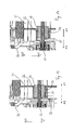
- a headrest as a whole is denoted by the reference numeral 10 in the figures.
- Like reference numerals in the various figures indicate corresponding parts, even if small letters are readjusted or omitted.
- the headrest 10 comprises a carrier 11, which is secured with support rods 12 to the backrest of a vehicle seat, not shown.
- the carrier 11 is in a manner not shown in the direction y1, y2 adjustable in height. This can e.g. done by an adjustment of the carrier 11 relative to the support rods 12.
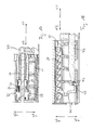
- the headrest 10 further comprises a head attachment part 13 which is mounted movably in the carrier 11 in the direction x1, x2. Attached to the headrest part 13 is a spindle 14 which can be driven by a motor 15 to move the headrest part 13 in the direction x1, x2.
- a spindle nut 16 (see the Fig. 3 and 5 ) has an internal thread which is in engagement with the external thread of the spindle 14.
- the spindle nut 16 is fixed to the carrier 11, so that the spindle 14 can be supported on the spindle nut 16.
- the head abutment part 13 becomes in the direction x1
- the head abutment part is moved in the direction x2.
- Further bearings 33 can be seen, which are formed in the carrier 11.
- the carrier 11 is mounted on the support rods 12.
- the bearings 33 include ribs, with which the carrier is guided on the support rods 12.
- An overload protection 17 comprises a slide 18 and a securing bracket 19.
- the securing bracket 19 forms with the support 11 pivot joints G1 and G2 and is pivotable in this manner about a rotation axis a.
- In a basic position of the overload protection 17 are support surfaces 20 of the securing bracket 19 with retaining surfaces 21 of the slider 18 in contact.
- the spring clip 25 comprises arms 26, which are provided at their free end portions with beads 27.
- the beads 27 are formed complementary to recesses 28 which are formed by a seat 32 of the carrier 11.
- the seat 32 also has guide surfaces 29, which are provided for guiding outer surfaces 30 of the spindle nut 16.
- the arms 26 are biased in the direction w1 and loaded in this way in the engagement direction with the recesses 28.
- Exceeding a maximum permissible force is transmitted via the spindle 14 to the spindle nut 16, the arms 26 move by elastic deformation in the direction w2 out of engagement with the recesses 28.
- the spindle nut 16 is then no longer held in their seat and outer surfaces 30 of Spindle nut 16 slide along the Guide surfaces 29 in the direction x1 in the tripping position shown in FIG.
- a secured to the securing bracket 19 web 31 is connected to the spindle nut 16.
- the spindle nut 16 By the movement of the spindle nut 16 from the basic position to the release position of the securing bracket 19 is pivoted about the pivot axis a in the direction v2 (see Fig. 9 ).
- the support surfaces 20 are disengaged from the retaining surfaces 21.
- the slider 18 is moved by the springs 22 from the basic position in the direction z2 in engagement with the toothing 24 in the release position.
- In the release position is due to the tooth geometry of the toothing 24, which is a form-Richtgesperre, a movement of the headrest part 13 in the direction x2 possible, a movement in the direction x1 but locked.
- the slider 18 In order to return the headrest 10 back to its original position, the slider 18 must be moved again in the direction z1 and the support surfaces 20 must again be brought into engagement with the holding surface 21 by the securing bracket 19 being pivoted back in the direction v1. Further, the spindle nut 16 in the direction x2 Scotlandverlagern in their seat until the beads 27 are in engagement with the recesses 28.
- the headrest 10 has a second drive for a height adjustment, which a second spindle 34 and an electric motor 35 are assigned.
- FIGS. 13 and 14 a second embodiment is shown.
- the operation of the headrest according to the second embodiment is basically the same as that of the first embodiment.
- the difference to the first embodiment is only that the spindle nut 16 is not connected via a securing bracket with the slider.
- the spindle 14 has an external thread which is in engagement with an internal thread of the spindle nut 16.
- a slider 36 includes a control 37 which is fixed to the slider 36.
- the slider 36 and the control member 37 could also be a part.
- Fig. 13 is the spindle nut 16 in the path of movement of the control element 37 when it is arranged in its seat 32.
- a contact surface 38 of the control element 37 bears against an outer surface 39 of the spindle nut 16.
- the slider 36 which is spring loaded in direction y2, therefore can not move in the direction y2.
- a third embodiment is in the 15 to 18 shown.
- the operation of the headrest according to the third embodiment is basically the same as that of the first embodiment. The difference is that instead of the securing bow 19 a securing slide 40 is provided, which cooperates with a slide 41.
- the spindle 14 and the spindle nut 16 function in the same manner as in the first embodiment.
- the spindle nut 16 is in its seat 32.
- a safety slide 40 is movably mounted in the direction x1, x2 and connected in movement with the spindle nut 16.
- the safety slide 40 includes a locking cam 42 (see Fig. 16 ), which in the basic position of the overload protection according to Fig. 16 in the trajectory of a slider 41 is arranged. The slider 41 is held in this way out of engagement with the teeth 24.
Landscapes
- Engineering & Computer Science (AREA)
- Aviation & Aerospace Engineering (AREA)
- Transportation (AREA)
- Mechanical Engineering (AREA)
- Seats For Vehicles (AREA)
- Chair Legs, Seat Parts, And Backrests (AREA)
Abstract
Description
- Die Erfindung betrifft eine Kopfstütze. Eine solche Kopfstütze ist z.B. in der
DE 35 19 351 C2 beschrieben. Die Kopfstütze weist eine Höhenverstellung auf, wobei ein das Kopfpolster tragender Kopfkasten relativ zu den Tragstangen mittels eines elektrischen Antriebsmotors verlagerbar ist. Der Antriebsstrang umfasst eine Überlastsicherung derart, dass der Antriebsmotor und Wellen, die den Kopfkasten antreiben, durch eine drehelastische Kupplung drehverbunden sind. Gemäß einem zweiten Aspekt der Erfindung besteht die Überlastsicherung darin, dass die Wellen jeweils Antriebsräder aufweisen, die auf einer Laufbahn abrollen, welche der Tragstange zugeordnet ist. Das Antriebsrad ist als Reibrad ausgestaltet. - In der
DE 10 2009 049 946 A1 ist eine Kopfstütze beschrieben, die eine an Tragstangen befestigte Trägerplatte sowie eine relativ zu der Trägerplatte in X-Richtung verlagerbare Platte umfasst. Eine Führungsvorrichtung umfasst der Platte zugeordnete Führungsstangen, die in Führungsbuchsen gelagert sind, welche der Trägerplatte zugeordnet sind. Der Antrieb der Platte erfolgt über eine Antriebswelle, die mit zwei Zahnrädern versehen ist, wobei jedes Zahnrad mit einer an der Führungsstange befestigten Zahnschiene zusammenwirkt. Auf der Antriebswelle ist ein Sperrrad befestigt. Ein Verriegelungsmittel ist lösbar mit dem Sperrad in Eingriff bringbar. Befindet sich das Verriegelungsmittel in Eingriff mit dem Sperrad ist die Bewegung der Platte blockiert. - In der
DE 198 00 040 B4 ist eine Kopfstütze beschrieben, die mittels Verzahnungen höhenverstellbar ist, wobei durch die Höhenverstellung zugleich eine Neigeverstellung des Kopfanlageteils durchgeführt wird. - Die
DE 297 23 240 U1 beschreibt eine Kopfstütze, bei welcher die Sitzhöhenverstellung mit der Höhenverstellung der Kopfstütze gekoppelt ist. Wird der Sitz angehoben, stellt sich die Kopfstütze nach unten. Wird der Sitz gesenkt, stellt sich die Kopfstütze nach oben. Bei einem Ausführungsbeispiel erfolgt der Antrieb der Höhenverstellung der Kopfstütze über eine Zahnweile, die mit Verzahnungen der Kopfstützentragstangen zusammenwirkt. - In der
DE 10 2004 030 319 A1 ist eine Kopfstütze beschrieben, bei welcher ein Kopfanlageteil höhenverstellbar auf Tragstangen gelagert ist. Den Tragstangen ist eine Verzahnung zugeordnet, die mit einem Antriebsritzel zusammenwirkt, um die Kopfstütze in der Höhe zu verstellen. Ein flexibles Kopfpolster ist über das Kopfanlageteil gelegt und in seiner Form veränderbar ausgebildet. - Es war Aufgabe der Erfindung eine Kopfstütze zu schaffen, die wenigstens eine Verstellmöglichkeit aufweist, und die dennoch eine große Sicherheit bietet.
- Die Aufgabe wird gelöst durch eine Kopfstütze mit den Merkmalen des Anspruchs 1.
- Die Kopfstütze ist mittels mindesten einer Tragstange an der Rückenlehne eines Fahrzeugsitzes gehalten. Die Kopfstütze umfasst wenigstens ein Verstellteil, welches mit mindestens einem Antrieb relativ zu der Rückenlehne verlagerbar ist. Z.B. ist das Verstellteil horizontal verstellbar und relativ zu einem Träger verlagerbar, welcher auf der Tragstange gelagert ist. Zusätzlich oder gemäß einer alternativen Ausführungsform ist der Träger relativ zu der Tragstange oder relativ zu der Rückenlehne verlagerbar. Die Kopfstütze umfasst eine erste Antriebseinrichtung, die mittelbar oder unmittelbar an dem Verstellteil befestigt ist. Des Weiteren umfasst die Kopfstütze eine zweite Antriebseinrichtung, die mittelbar oder unmittelbar an der Rückenlehne befestigt ist. Z.B. ist die zweite Antriebseinrichtung an dem Träger der Kopfstütze befestigt.
- Träger ist im Sinne ein Teil, welches unbewegbar oder bewegbar an der Tragstange befestigt ist. Der Träger kann z.B. an zwei Tragstangen befestigt sein und diese miteinander verbinden.
- Der Antrieb umfasst eine Überlastsicherung, welche zwischen einer Grundposition und einer Auslöseposition bewegbar ist. Durch Überschreiten einer auf das Verstellteil wirkenden Maximalkraft ist die Überlastsicherung von der Grundposition in die Auslöseposition bewegbar. In der Auslöseposition ist der Antrieb teilweise oder vollständig von der auf das Verstellteil wirkenden Kraft entlastet. Z.B. wirkt in der Auslöseposition keine Kraft mehr von dem Verstellteil auf den Antrieb. Gemäß einer alternativen Ausführungsform wird ein Teil der auf das Verstellteil wirkenden Kraft nicht von dem Antrieb sondern von wenigstens einem anderem Teil der Kopfstütze aufgenommen. Z.B. kann wenigstens ein Teil der auf das Verstellteil wirkenden Kraft von dem Träger aufgenommen werden.
- Der Vorteil der Erfindung besteht darin, dass durch eine hohe auf das Verstellteil wirkende Kraft der Antrieb nicht zerstört wird.
- Eine Ausführungsform ist dadurch gekennzeichnet, dass die Überlastsicherung eine Kupplung umfasst welche aus einer Kupplungsposition in eine Entkupplungsposition bewegbar ist. Die Kupplung kann z.B. dem Antriebsstrang für das Verstellteil zugeordnet sein. Die Kupplung umfasst wenigstens erste und zweite Kupplungsmittel, die zwischen einer Kupplungsposition und einer Entkupplungsposition bewegbar sind. Die Kupplungsmittel werden z.B. durch Überschreiten einer auf die Kupplungsteile wirkenden Maximalkraft von der Kupplungsposition in die Entkupplungsposition bewegt.
- Die ersten Kupplungsmittel sind z.B. einer Spindelmutter des Antriebs des Verstellteils und die zweiten Kupplungsmittel einem an dem Träger ausgebildeten Sitz für die Spindelmutter zugeordnet. Die Kupplung kann derart ausgebildet sein, dass sie aus der Enkupplungsposition in die Kupplungsposition rückstellbar ist. Alternativ kann die Kupplung z.B. derart ausgebildet sein, dass sie lediglich von der Kupplungsposition in die Entkupplungsposition bewegbar ist. Das ist z.B. der Fall, wenn durch das Bewegen in die Entkupplungsposition Teile der Kupplung zerstört oder plastisch verformt werden.
- Eine weitere Ausführungsform ist dadurch gekennzeichnet, dass die Kupplung der ersten Antriebseinrichtung und / oder der zweiten Antriebseinrichtung zugeordnet ist. Die Kupplung kann z.B. in die erste Antriebseinrichtung oder in die zweite Antriebseinrichtung integriert sein. Die Kupplung kann z.B. zwischen der ersten und der zweiten Antriebseinrichtung ausgebildet sein.
- Eine andere Ausgestaltung der Erfindung ist dadurch gekennzeichnet, dass der Antrieb eine Spindel und eine Spindelmutter umfasst, wobei die Spindel mit der Spindelmutter in Eingriff ist. Die Spindel ist z.B. der ersten Antriebseinrichtung und die Spindelmutter der zweiten Antriebseinrichtung zugeordnet. Die Spindelmutter ist z.B. einem Träger der Kopfstütze zugeordnet. Die Spindel ist z.B. an dem Verstellteil befestigt. Durch Drehen der Spindel ist dann z.B. das Verstellteil relativ zu dem rückenlehnenfesten Teil, z.B. dem Träger, bewegbar. Das Drehen der Spindel kann z.B. durch einen Antriebsmotor erfolgen.
- Eine andere Ausführungsform zeichnet sich dadurch aus, dass die Kupplung eine Feder umfasst, wobei die elastische Rückstellkraft der Feder die Kupplung durch Kraftschluss in der Kupplungsposition, z.B. in einem Federsitz, hält und bei einem Überschreiten der auf das Verstellteil wirkenden Maximalkraft die Kupplung durch Lösen des Kraftschlusses in die Entkupplungsposition bewegbar ist.
- Die Feder ist z.B. der Spindelmutter zugeordnet. Z.B. ist die Feder fest an der Spindelmutter gehalten.
- Eine andere Ausgestaltung der Erfindung ist dadurch gekennzeichnet, dass die Feder mit ersten Formschlusselementen versehen ist, welche mit zweiten Formschlusselementen eines Federsitzes formschlüssig lösbar in Eingriff bringbar sind. Z.B. ist der Federsitz dem Träger der Kopfstütze zugeordnet.
- Die Überlastsicherung umfasst z.B. eine Verriegelungsvorrichtung, welche durch eine Bewegung der Kupplung aus der Kupplungsposition in die Entkupplungsposition aus einer entriegelten Position in eine verriegelte Position bewegt wird, wobei in der verriegelten Position eine Bewegung des Verstellteils arretiert ist. Auf diese Weise wird die auf das Verstellteil wirkende Kraft von der Verriegelungsvorrichtung aufgenommen und wirkt nicht mehr auf den Antrieb.
- Z.B. umfasst die Verriegelungsvorrichtung wenigstens ein erstes rückenlehnenfestes Verriegelungselement, welches mit mindestens einem zweiten verstellteilfesten Verriegelungselement lösbar in Eingriff bringbar ist. Das rückenlehnenfeste Teil ist z.B. an einem Träger gehalten. Das erste Verriegelungselement wird z.B. von einem Halteelement außer Eingriff mit dem zweiten Verriegelungselement gehalten. Das Halteelement ist z.B. mit der Kupplung derart verbunden, dass es bei einer Bewegung der Kupplung in die Entkupplungsposition, das erste Verriegelungselement freigibt, so dass es sich in Eingriff mit dem zweiten Verriegelungselement bewegen kann.
- Das erste Verriegelungselement ist z.B. von einem Schieber und das zweite Verriegelungselement z.B. von einer Verzahnung gebildet. Der Schieber ist z.B. von dem Halteelement außer Eingriff mit der Verzahnung gehalten. Der Schieber kann z.B. in Eingriff mit der Verzahnung belastet sein. Der Schieber wird z.B. von einem Sicherungsbügel außer Eingriff mit der Verzahnung gehalten. Durch Bewegen der Kupplung in die Entkupplungsposition wird beispielsweise der Sicherungsbügel verschwenkt und gibt den Schieber frei, so dass sich dieser in Eingriff mit der Verzahnung bewegen kann.
- Weitere Vorteile der Erfindung ergeben sich anhand eines in den Fig. dargestellten Ausführungsbeispiels. Es zeigen:
-
Fig.1 eine schematische perspektivische Darstellung der erfindungsgemäßen Kopfstütze wobei sich eine Überlastsicherung in der Grundposition befindet, -
Fig. 2 die Kopfstütze in Anlehnung anFig. 1 , wobei sich die Überlastsicherung in der Auslöseposition befindet, -
Fig. 3 eine schematische rückwärtige Längsschnittdarstellung der Kopfstütze, wobei sich die Überlastsicherung in der Grundposition befindet, -
Fig. 4 in Anlehnung anFig. 3 die Kopfstütze, wobei sich die Überlastsicherung in der Auslöseposition befindet, -
Fig. 5 eine schematische Querschnittdarstellung gemäß Schnittlinie V-V inFig. 3 , -
Fig. 6 eine vergrößerte Darstellung des Ausschnitts gemäß Ausschnittlinie VI inFig. 5 , -
Fig. 7 eine schematische Querschnittdarstellung gemäß Schnittlinie VII-VII inFig. 4 -
Fig. 8 eine vergrößerte Darstellung des Ausschnitts gemäß Ausschnittlinie VIII inFig. 7 , -
Fig. 9 eine schematische Längsschnittdarstellung der Kopfstütze gemäß Schnittlinie IX-IX inFig. 3 , -
Fig. 10 eine schematische Längsschnittdarstellung der Kopfstütze gemäß Schnittlinie X-X inFig. 4 , -
Fig. 11 eine schematische Längsschnittdarstellung der Kopfstütze gemäß Schnittlinie XI-XI inFig. 3 , -
Fig. 12 eine schematische Längsschnittdarstellung der Kopfstütze gemäß Schnittlinie XII-XII inFig. 4 . -
Fig. 13 eine schematische Ausschnittdarstellung eines zweiten Ausführungsbeispiels der Kopfstütze, wobei sich die Überlastsicherung in der Grundposition befindet, -
Fig. 14 eine schematische Ausschnittdarstellung in Anlehnung anFig. 13 , wobei sich die Überlastsicherung in der Auslöseposition befindet, -
Fig. 15 eine schematische Ausschnittdarstellung eines dritten Ausführungsbeispiels der Kopfstütze, wobei sich die Überlastsicherung in der Grundposition befindet, -
Fig. 16 eine schematische Ausschnittdarstellung des dritten Ausführungsbeispiels der Kopfstütze in einer anderen Schnittebene, -
Fig. 17 in Anlehnung anFig. 15 die Kopfstütze, wobei sich die Überlastsicherung in der Auslöseposition befindet, und -
Fig. 18 in Anlehnung anFig. 16 die Kopfstütze in der Auslöseposition. - Eine Kopfstütze insgesamt wird in den Fig. mit dem Bezugszeichen 10 bezeichnet. Gleiche Bezugszeichen in den unterschiedlichen Fig. bezeichnen entsprechende Teile, auch wenn kleine Buchstaben nachgestellt oder weggelassen sind.
- Die Kopfstütze 10 umfasst einen Träger 11, welcher mit Tragstangen 12 an der Rückenlehne eines nicht dargestellten Fahrzeugsitzes befestigt ist. Der Träger 11 ist in nicht dargestellter Weise in Richtung y1, y2 in der Höhe verstellbar. Dies kann z.B. durch eine Verstellung des Trägers 11 relativ zu den Tragstangen 12 erfolgen. Die Kopfstütze 10 umfasst ferner ein Kopfanlageteil 13, welches in Richtung x1, x2 bewegbar in dem Träger 11 gelagert ist. An dem Kopfanlageteil 13 ist eine Spindel 14 befestigt, die von einem Motor 15 angetrieben werden kann, um das Kopfanlageteil 13 in Richtung x1, x2 zu bewegen.
- Eine Spindelmutter 16 (siehe die
Fig. 3 und5 ) weist ein Innengewinde auf, welches mit dem Außengewinde der Spindel 14 in Eingriff ist. Die Spindelmutter 16 ist an dem Träger 11 befestigt, so dass sich die Spindel 14 an der Spindelmutter 16 abstützen kann. Wenn die Spindel 14 in Richtung u1 dreht, wird das Kopfanlageteil 13 in Richtung x1 und wenn die Spindel 14 in Richtung u2 dreht wird das Kopfanlageteil in Richtung x2 bewegt. InFig. 5 sind ferner Lagerungen 33 erkennbar, die in den Träger 11 eingeformt sind. Mittels der Lagerungen 33 ist der Träger 11 auf den Tragstangen 12 gelagert. Die Lagerungen 33 umfassen Rippen, mit denen der Träger an den Tragstangen 12 geführt ist. - Eine Überlastsicherung 17 umfasst einen Schieber 18 sowie einen Sicherungsbügel 19. Der Sicherungsbügel 19 bildet mit dem Träger 11 Drehgelenke G1 und G2 und ist auf diese Weise um eine Drehachse a schwenkbar. In einer Grundposition der Überlastsicherung 17 stehen Stützflächen 20 des Sicherungsbügels 19 mit Halteflächen 21 des Schiebers 18 in Kontakt. Der Schieber 18, welcher in Richtung z1, z2 bewegbar in dem Träger 11 gelagert und von Federn 22 in Richtung z2 belastet ist, kann sich daher aus der in
Fig. 1 dargestellten Grundposition nicht in Richtung z2 in Richtung der Verriegelungsposition bewegen. - In der Verriegelungsposition, die in
Fig. 2 dargestellt ist, befinden sich Anschläge 23 des Schiebers 18 nicht in Eingriff mit einer Verzahnung 24, welche an dem Kopfanlageteil 13 befestigt ist. In der Auslöseposition der Kopfstütze 10, die durch Überbelastung des Kopfanlageteils 13 in Richtung x1 hervorgerufen wird, befinden sich die Anschläge 23 in Eingriff mit den Verzahnungen 24. - An der Spindelmutter 16 ist eine Federklammer 25 befestigt. Die Federklammer 25 umfasst Arme 26, die an ihren freien Endbereichen mit Wulsten 27 versehen sind. Die Wulste 27 sind komplementär zu Vertiefungen 28 ausgebildet, welche von einem Sitz 32 des Trägers 11 gebildet sind. Der Sitz 32 weist zudem Führungsflächen 29 auf, welche zur Führung von Außenflächen 30 der Spindelmutter 16 vorgesehen sind. Die Arme 26 sind in Richtung w1 vorgespannt und auf diese Weise in Eingriffsrichtung mit den Vertiefungen 28 belastet. Bei Überschreitung einer zulässigen Höchstkraft die über die Spindel 14 auf die Spindelmutter 16 übertragen wird, bewegen sich die Arme 26 durch elastische Verformung in Richtung w2 außer Eingriff mit den Vertiefungen 28. Die Spindelmutter 16 ist dann nicht mehr in ihrem Sitz gehalten und Außenflächen 30 der Spindelmutter 16 gleiten entlang der Führungsflächen 29 in Richtung x1 in die in Fig. dargestellte Auslöseposition.
- Ein an dem Sicherungsbügel 19 befestigter Steg 31 ist mit der Spindelmutter 16 verbunden. Durch die Bewegung der Spindelmutter 16 von der Grundposition in die Auslöseposition wird der Sicherungsbügel 19 um die Schwenkachse a in Richtung v2 geschwenkt (siehe
Fig. 9 ). Dabei geraten die Stützflächen 20 außer Eingriff mit den Halteflächen 21. Der Schieber 18 wird von den Federn 22 aus der Grundposition in Richtung z2 in Eingriff mit der Verzahnung 24 in die Auslöseposition bewegt. In der Auslöseposition ist aufgrund der Zahngeometrie der Verzahnung 24, die ein Form-Richtgesperre darstellt, eine Bewegung des Kopfanlageteils 13 in Richtung x2 möglich, eine Bewegung in Richtung x1 jedoch verriegelt. - Um die Kopfstütze 10 wieder in ihre Ausgangsposition zurückzuversetzen, muss der Schieber 18 wieder in Richtung z1 bewegt werden und die Stützflächen 20 müssen wieder mit den Haltefläche 21 in Eingriff gebracht werden, indem der Sicherungsbügel 19 in Richtung v1 zurück geschwenkt wird. Ferner ist die Spindelmutter 16 in Richtung x2 in ihren Sitz zurückzuverlagern, bis die Wulste 27 in Eingriff mit den Vertiefungen 28 sind.
- Der Vollständigkeit halber sei noch erwähnt, dass die Kopfstütze 10 einen zweiten Antrieb für eine Höhenverstellung aufweist, welchem eine zweite Spindel 34 sowie ein elektrischer Motor 35 zugeordnet sind.
- In den
Fig. 13 und 14 ist ein zweites Ausführungsbeispiel dargestellt. Die Funktionsweise der Kopfstütze gemäß dem zweiten Ausführungsbeispiel gleicht grundsätzlich der des ersten Ausführungsbeispiels. Der Unterschied zu dem ersten Ausführungsbeispiel besteht lediglich darin, dass die Spindelmutter 16 nicht über einen Sicherungsbügel mit dem Schieber verbunden ist. GemäßFig. 13 weist die Spindel 14 ein Außengewinde auf, welches mit einem Innengewinde der Spindelmutter 16 in Eingriff ist. Ein Schieber 36 umfasst ein Steuerelement 37, das an dem Schieber 36 befestigt ist. In einer alternativen Ausführungsform könnten der Schieber 36 und das Steuerelement 37 auch ein Teil sein. GemäßFig. 13 befindet sich die Spindelmutter 16 in der Bewegungsbahn des Steuerelements 37, wenn sie in ihrem Sitz 32 angeordnet ist. Eine Kontaktfläche 38 des Steuerelements 37 liegt an einer Außenfläche 39 der Spindelmutter 16 an. Der Schieber 36, welcher in Richtung y2 federbelastet ist, kann sich daher nicht in Richtung y2 bewegen. - Bei Überlast auf das in
Fig. 13 nicht dargestellte Kopfanlageteil wird die Spindelmutter 16 in Richtung x1 aus ihrem Sitz 32 in die inFig. 14 dargestellte Auslöseposition bewegt. Die Spindelmutter 16 befindet sich nicht mehr in der Bewegungsbahn des Steuerelements 37. Der Schieber 36 kann sich daher in Richtung y2 in Eingriff mit der Verzahnung 24 bewegen. - Ein drittes Ausführungsbeispiel ist in den
Fig. 15 bis 18 dargestellt. Die Funktionsweise der Kopfstütze gemäß dem dritten Ausführungsbeispiel gleicht grundsätzlich der des ersten Ausführungsbeispiels. Der Unterschied besteht darin, dass anstelle des Sicherungsbügels 19 ein Sicherungsschieber 40 vorgesehen ist, welcher mit einem Schieber 41 zusammenwirkt. - Die Spindel 14 und die Spindelmutter 16 funktionieren in der gleichen Weise wie bei dem ersten Ausführungsbeispiel. Gemäß
Fig. 15 befindet sich die Spindelmutter 16 in ihrem Sitz 32. Ein Sicherungsschieber 40 ist in Richtung x1, x2 bewegbar gelagert und mit der Spindelmutter 16 bewegungsverbunden. Der Sicherungsschieber 40 umfasst einen Sperrnocken 42 (sieheFig. 16 ), welcher in der Grundposition der Überlastsicherung gemäßFig. 16 in der Bewegungsbahn eines Schiebers 41 angeordnet ist. Der Schieber 41 ist auf diese Weise außer Eingriff mit der Verzahnung 24 gehalten. - Wird die Spindelmutter 16 durch Überlast auf das in
Fig. 15 nicht dargestellte Kopfanlageteil in Richtung x1 in die Auslöseposition bewegt, verlagert sich der Sicherungsschieber 40 aufgrund der Bewegungskopplung ebenfalls in Richtung x1. Die Auslöseposition ist in denFig. 17 und 18 dargestellt. Die Spindelmutter 16 ist aus ihrem Sitz 32 herausbewegt. Der Sicherungsschieber 40 ist bezüglich der in demFig. 15 und 16 gezeigten Position ebenfalls in Richtung x1 verlagert. Der Sperrnocken 42 befindet sich nicht mehr in der Bewegungsbahn einer Rückhaltebereichs 43 des Schiebers 41. Da der Schieber 41 in Richtung y2 federbelastet ist, bewegt er sich in Richtung y2 in Eingriff mit der Verzahnung 24. Das Kopfanlageteil ist dann verriegelt und kann nicht mehr in Richtung x1 bewegt werden.
Claims (10)
- Kopfstütze für Fahrzeugsitze, die mittels wenigstens einer Tragstange (12) an dem Fahrzeugsitz gehalten ist, wobei die Kopfstütze (10) wenigstens ein Verstellteil (13) umfasst welches mit mindestens einem Antrieb (14, 15, 16, 22) relativ zu der Rückenlehne verlagerbar ist, wobei der Antrieb (14, 15, 16, 22) mindestens eine erste verstellteilfeste Antriebseinrichtung (14, 15) und eine zweite rückenlehnenfeste Antriebseinrichtung (16, 22) umfasst, dadurch gekennzeichnet, dass der Antrieb (14, 15, 16, 22) eine Überlastsicherung (17) umfasst, welche durch Überschreiten einer auf das Verstellteil (13) wirkenden Maximalkraft von einer Grundposition in eine Auslöseposition bewegbar ist, wobei in der Auslöseposition der Antrieb (14, 15, 16, 22) teilweise oder vollständig von der auf das Verstellteil (13) wirkenden Kraft entlastet ist.
- Kopfstütze nach Anspruch 1, dadurch gekennzeichnet, dass die Überlastsicherung (17) eine Kupplung (22, 32) umfasst welche aus einer Kupplungsposition in eine Entkupplungsposition bewegbar ist.
- Kopfstütze nach einem der vorangehenden Ansprüche, dadurch gekennzeichnet, dass die Kupplung (22, 32) der ersten Antriebseinrichtung und / oder der zweiten Antriebseinrichtung (16, 22) zugeordnet ist.
- Kopfstütze nach einem der vorangehenden Ansprüche, dadurch gekennzeichnet, dass der Antrieb eine Spindel (14) und eine Spindelmutter (16) umfasst, wobei die Spindel (14) mit der Spindelmutter (16) in Eingriff ist.
- Kopfstütze nach einem der vorangehenden Ansprüche, dadurch gekennzeichnet, dass die Kupplung eine Feder (22) umfasst, welche die Kupplung in der Kupplungsposition hält und bei einem Überschreiten der Maximalkraft durch Verformung der Feder (22) die Kupplung in die Entkupplungsposition bewegbar ist.
- Kopfstütze nach einem der vorangehenden Ansprüche, dadurch gekennzeichnet, dass die Feder (22) der Spindelmutter (16) zugeordnet ist.
- Kopfstütze nach einem der vorangehenden Ansprüche, dadurch gekennzeichnet, dass die Feder (22) mit ersten Formschlusselementen (27) versehen ist, welche mit zweiten Formschlusselementen (28) eines Federsitzes (32) formschlüssig lösbar in Eingriff bringbar sind.
- Kopfstütze nach einem der vorangehenden Ansprüche, dadurch gekennzeichnet, dass die Überlastsicherung (17) eine Verriegelungsvorrichtung (18, 19, 24) umfasst, welche durch eine Bewegung der Kupplung aus der Kupplungsposition in die Entkupplungsposition aus einer entriegelten Position in eine verriegelte Position bewegt wird, wobei in der verriegelten Position eine Bewegung des Verstellteils (13) arretiert ist.
- Kopfstütze nach einem der vorangehenden Ansprüche, dadurch gekennzeichnet, dass die Verriegelungsvorrichtung (18, 19, 24) wenigstens ein erstes rückenlehnenfestes Verriegelungselement (18, 19) umfasst, welches mit mindestens einem zweiten verstellteilfesten Verriegelungselement (24) lösbar in Eingriff bringbar ist.
- Kopfstütze nach einem der vorangehenden Ansprüche, dadurch gekennzeichnet, dass das erste Verriegelungselement von einem Schieber (18) und das zweite Verriegelungselement von einer Verzahnung (24) gebildet ist.
Applications Claiming Priority (1)
| Application Number | Priority Date | Filing Date | Title |
|---|---|---|---|
| DE102012003367A DE102012003367A1 (de) | 2012-02-22 | 2012-02-22 | Kopfstütze |
Publications (3)
| Publication Number | Publication Date |
|---|---|
| EP2631116A2 true EP2631116A2 (de) | 2013-08-28 |
| EP2631116A3 EP2631116A3 (de) | 2016-04-06 |
| EP2631116B1 EP2631116B1 (de) | 2018-11-28 |
Family
ID=47877689
Family Applications (1)
| Application Number | Title | Priority Date | Filing Date |
|---|---|---|---|
| EP13000912.9A Active EP2631116B1 (de) | 2012-02-22 | 2013-02-22 | Kopfstütze |
Country Status (4)
| Country | Link |
|---|---|
| US (1) | US9555727B2 (de) |
| EP (1) | EP2631116B1 (de) |
| CN (1) | CN103287294B (de) |
| DE (1) | DE102012003367A1 (de) |
Cited By (3)
| Publication number | Priority date | Publication date | Assignee | Title |
|---|---|---|---|---|
| WO2017095891A1 (en) * | 2015-11-30 | 2017-06-08 | B/E Aerospace, Inc. | Forward translating headrest |
| EP3275726A1 (de) * | 2016-07-27 | 2018-01-31 | Windsor Machine and Stamping 2009 Ltd | Kopfstütze mit vierwege-strombetätigung |
| WO2021180344A1 (en) * | 2020-03-11 | 2021-09-16 | Brose Fahrzeugteile SE & Co. Kommanditgesellschaft, Coburg | Headrest with an adjustment device |
Families Citing this family (10)
| Publication number | Priority date | Publication date | Assignee | Title |
|---|---|---|---|---|
| DE102010010537B4 (de) * | 2010-03-05 | 2012-10-25 | Johnson Controls Gmbh | Kopfstütze, insbesondere für ein Kraftfahrzeug |
| US20190168649A1 (en) * | 2016-07-26 | 2019-06-06 | Adient Luxembourg Holding S.Á.R.L. | Adjustable head restraint |
| DE102016219104A1 (de) * | 2016-09-30 | 2018-04-05 | Brose Fahrzeugteile Gmbh & Co. Kg, Coburg | Verstellvorrichtung einer Lordosenstütze oder eines Seitenwangenverstellers mit Spindelantrieb für ein Sitzelement eines Fahrzeugsitzes |
| KR101870345B1 (ko) * | 2016-10-14 | 2018-06-22 | 주식회사 우보테크 | 헤드레스트 이동장치 |
| FR3068312B1 (fr) * | 2017-06-29 | 2019-08-23 | Cera Tsc | Appui-tete de siege de vehicule automobile |
| CN112262058B (zh) * | 2018-06-11 | 2023-04-21 | 安道拓美国有限责任公司 | 高度可调节和纵向可调节的头枕 |
| CN109455127B (zh) * | 2018-11-11 | 2020-02-07 | 延锋安道拓座椅有限公司 | 一体式激发机构 |
| DE102018009229B4 (de) * | 2018-11-26 | 2021-09-02 | Grammer Aktiengesellschaft | Fahrzeugausstattungsteil |
| DE102018221626B3 (de) | 2018-12-13 | 2019-10-24 | Magna Seating (Germany) Gmbh | Verstellbare Kopfstützenanordnung für einen Kraftfahrzeugsitz |
| DE102018221622B3 (de) | 2018-12-13 | 2019-10-24 | Magna Seating (Germany) Gmbh | Verstellbare Kopfstützenanordnung für einen Kraftfahrzeugsitz |
Citations (5)
| Publication number | Priority date | Publication date | Assignee | Title |
|---|---|---|---|---|
| DE3519351C2 (de) | 1985-05-30 | 1988-07-14 | Eugen Otto 4010 Hilden De Butz | |
| DE29723240U1 (de) | 1997-05-30 | 1998-06-04 | Faure Bertrand Sitztech Gmbh | Fahrzeugsitz, insbesondere Kraftfahrzeugsitz, mit höhenverstellbarer Kopfstütze |
| DE102004030319A1 (de) | 2004-06-23 | 2006-01-12 | Faurecia Autositze Gmbh & Co. Kg | Kopfstützenanordnung für einen Fahrzeugsitz |
| DE19800040B4 (de) | 1998-01-02 | 2006-10-12 | Volkswagen Ag | Fahrzeugsitz mit einer Kopfstütze |
| DE102009049946A1 (de) | 2009-09-16 | 2011-03-31 | Johnson Controls Gmbh | In X-Richtung verstellbare Kopfstütze |
Family Cites Families (27)
| Publication number | Priority date | Publication date | Assignee | Title |
|---|---|---|---|---|
| US4552403A (en) * | 1983-09-29 | 1985-11-12 | Hamilton Industries | Power-operated medical examination table |
| US5112286A (en) * | 1987-06-11 | 1992-05-12 | Jones Arthur A | Method of testing and/or exercising the cervical muscles of the human body |
| US4821456A (en) * | 1988-05-02 | 1989-04-18 | Hisami Nogaki | Linear mechanical drive with precise end-of-travel load positioning |
| US5195390A (en) * | 1990-06-14 | 1993-03-23 | Hisami Nogaki | Precision linear mechanical drives |
| US5306073A (en) * | 1992-02-24 | 1994-04-26 | Itt Corporation | High strength motor vehicle seat recliner |
| US5338100A (en) * | 1992-02-24 | 1994-08-16 | Itt Corporation | High strength automotive seat frame and method |
| US5570508A (en) * | 1993-12-03 | 1996-11-05 | Itt Industries, Inc. | Method of making a high strength automotive seat frame |
| US6948756B2 (en) * | 1996-11-05 | 2005-09-27 | Xi Liu | Safety seat in a motor vehicle |
| DE19652476C2 (de) * | 1996-12-17 | 2002-10-17 | Microsonic Ges Fuer Mikroelekt | Kraftfahrzeugsitz mit hohem Sicherheitskomfort |
| US5772280A (en) * | 1997-05-08 | 1998-06-30 | Lear Corporation | Dynamic actuation system for an articulated headrest portion of an automotive seat |
| DE19919561B4 (de) * | 1999-04-29 | 2008-01-31 | Volkswagen Ag | Sicherheitsvorrichtung an einem Fahrzeugsitz mit Kopfstütze und Nackenstütze |
| DE19953630C5 (de) * | 1999-11-09 | 2006-12-07 | Keiper Gmbh & Co.Kg | Fahrzeugsitz mit Höheneinsteller |
| US6520582B2 (en) * | 2000-07-13 | 2003-02-18 | Patrick M. Glance | Quick adjustment restraint safety seat lead screw seat back recliner |
| WO2002066285A1 (fr) * | 2001-02-21 | 2002-08-29 | Daihatsu Motor Co., Ltd. | Siege de voiture |
| DE10137298C5 (de) * | 2001-08-01 | 2012-05-24 | Keiper Gmbh & Co. Kg | Fahrzeugsitz, insbesondere Kraftfahrzeugsitz, mit einem Höheneinsteller |
| DE10207807A1 (de) * | 2002-02-25 | 2003-09-04 | Hammerstein Gmbh C Rob | Einseitig arretierter Kraftfahrzeugsitz mit Rückhalteeinrichtung |
| US6863343B2 (en) * | 2002-06-26 | 2005-03-08 | Nissan Motor Co., Ltd. | Vehicle headrest apparatus |
| DE10306827B4 (de) * | 2003-02-19 | 2005-03-10 | Keiper Gmbh & Co Kg | Höheneinstellbarer Fahrzeugsitz mit Crashsperreneinheit |
| DE10306828B4 (de) * | 2003-02-19 | 2005-03-10 | Keiper Gmbh & Co Kg | Höheneinstellbarer Fahrzeugsitz mit Crashsperreneinheit |
| WO2005042298A1 (ja) * | 2003-10-30 | 2005-05-12 | Shiroki Kogyo Co., Ltd. | シート |
| ATE421931T1 (de) * | 2004-05-14 | 2009-02-15 | Alfmeier Praez Ag | Fahrzeugsitz mit einer kopfstütze |
| DE102005045461B3 (de) * | 2005-09-22 | 2007-01-25 | Johnson Controls Gmbh | Fahrzeugsitz mit einer crash-aktiven Kopfstütze, die eine Überlastsicherung aufweist |
| DE102007036466A1 (de) * | 2006-12-18 | 2008-06-19 | Brose Fahrzeugteile Gmbh & Co. Kommanditgesellschaft, Coburg | Crash-optimierter Kraftfahrzeugsitz |
| DE102007024000A1 (de) * | 2007-05-22 | 2008-11-27 | Brose Fahrzeugteile Gmbh & Co. Kommanditgesellschaft, Coburg | Höhenverstellbare Mittenarmlehne |
| DE102009053555A1 (de) * | 2009-11-18 | 2011-05-19 | Dr. Ing. H.C. F. Porsche Aktiengesellschaft | Verdeckantrieb |
| US8794084B2 (en) * | 2010-03-18 | 2014-08-05 | Parker-Hannifin Corporation | Jam-tolerant electromechanical actuator |
| US8763484B2 (en) * | 2010-10-08 | 2014-07-01 | Woodstock Safety Mirror Company, Inc. | Breakaway drive system |
-
2012
- 2012-02-22 DE DE102012003367A patent/DE102012003367A1/de not_active Withdrawn
-
2013
- 2013-02-22 CN CN201310057416.2A patent/CN103287294B/zh active Active
- 2013-02-22 US US13/773,797 patent/US9555727B2/en active Active
- 2013-02-22 EP EP13000912.9A patent/EP2631116B1/de active Active
Patent Citations (5)
| Publication number | Priority date | Publication date | Assignee | Title |
|---|---|---|---|---|
| DE3519351C2 (de) | 1985-05-30 | 1988-07-14 | Eugen Otto 4010 Hilden De Butz | |
| DE29723240U1 (de) | 1997-05-30 | 1998-06-04 | Faure Bertrand Sitztech Gmbh | Fahrzeugsitz, insbesondere Kraftfahrzeugsitz, mit höhenverstellbarer Kopfstütze |
| DE19800040B4 (de) | 1998-01-02 | 2006-10-12 | Volkswagen Ag | Fahrzeugsitz mit einer Kopfstütze |
| DE102004030319A1 (de) | 2004-06-23 | 2006-01-12 | Faurecia Autositze Gmbh & Co. Kg | Kopfstützenanordnung für einen Fahrzeugsitz |
| DE102009049946A1 (de) | 2009-09-16 | 2011-03-31 | Johnson Controls Gmbh | In X-Richtung verstellbare Kopfstütze |
Cited By (4)
| Publication number | Priority date | Publication date | Assignee | Title |
|---|---|---|---|---|
| WO2017095891A1 (en) * | 2015-11-30 | 2017-06-08 | B/E Aerospace, Inc. | Forward translating headrest |
| EP3275726A1 (de) * | 2016-07-27 | 2018-01-31 | Windsor Machine and Stamping 2009 Ltd | Kopfstütze mit vierwege-strombetätigung |
| US10160361B2 (en) | 2016-07-27 | 2018-12-25 | Windsor Machine and Stamping (2009) Ltd. | Four-way electric power actuation head restraint |
| WO2021180344A1 (en) * | 2020-03-11 | 2021-09-16 | Brose Fahrzeugteile SE & Co. Kommanditgesellschaft, Coburg | Headrest with an adjustment device |
Also Published As
| Publication number | Publication date |
|---|---|
| CN103287294A (zh) | 2013-09-11 |
| US9555727B2 (en) | 2017-01-31 |
| EP2631116B1 (de) | 2018-11-28 |
| US20130229042A1 (en) | 2013-09-05 |
| CN103287294B (zh) | 2016-08-10 |
| DE102012003367A1 (de) | 2013-08-22 |
| EP2631116A3 (de) | 2016-04-06 |
Similar Documents
| Publication | Publication Date | Title |
|---|---|---|
| EP2631116B1 (de) | Kopfstütze | |
| DE102009059159B3 (de) | Lenksäule für ein Kraftfahrzeug | |
| DE102014201582A1 (de) | Längsverstelleinrichtung zum Längsverstellen eines Fahrzeugsitzes | |
| EP1862352A2 (de) | Kopfstütze für Fahrzeuge | |
| WO2013004450A1 (de) | Beschlagsystem für einen fahrzeugsitz | |
| EP3206908A1 (de) | Kopfstütze für einen fahrzeugsitz | |
| WO2012100905A2 (de) | Feststelleinrichtung zum feststellen einer lenkspindellagereinheit | |
| WO2014114313A1 (de) | Gurtschlossbringer für einen sicherheitsgurt eines fahrzeuges | |
| EP3915829B1 (de) | Fahrzeugsitzbeschlag und fahrzeugsitz | |
| EP2694324B1 (de) | Fahrzeugsitz | |
| EP3353040A1 (de) | Einstellbare lenksaeule fuer ein kraftfahrzeug | |
| DE102018109611B4 (de) | Kopfstütze | |
| DE102005005826B4 (de) | Kopfstütze | |
| WO2019219749A1 (de) | Verstellvorrichtung mit verzahnungssteuerung | |
| DE102008011560B3 (de) | Verriegelungsvorrichtung, insbesondere für eine Kopfstütze für Fahrzeugsitze | |
| EP3831650B1 (de) | Ausstattungsvorrichtung | |
| DE102010045423B4 (de) | Feststellvorrichtung für verstellbare Kraftfahrzeuglenksäule | |
| WO2014086444A1 (de) | Gurtschlossbringer für ein fahrzeug | |
| EP3708421B1 (de) | Höhenverstelleinrichtung einer kopfstütze eines kindersitzes | |
| DE102012008702B4 (de) | Verstelleinrichtung für einen Fahrzeugsitz und Fahrzeugsitz | |
| DE102005058112A1 (de) | Arretiervorrichtung | |
| DE102006002069A1 (de) | Fahrzeugsitz, insbesondere Kraftfahrzeugsitz, mit einer Lehnen-bzw. einer Lehnen- und einer Höhenverstellung und einer Crashverlagerung der Rückenlehnenstruktur | |
| DE10209811B4 (de) | Cabriolet-Fahrzeug mit Verdeckklappe und mit dieser koppelbarem Überrollbügel | |
| DE102005049302B4 (de) | Fahrzeugsitz, insbesondere Kraftfahrzeugsitz, mit einer Höhen- und/oder Neigungsverstellung und einer Crashverlagerung der Rückenlehnenstruktur | |
| DE102007042753B4 (de) | Vorrichtung zur Höhenverstellung eines schulternahen Ankerpunktes eines Fahrzeugsicherheitsgurtes |
Legal Events
| Date | Code | Title | Description |
|---|---|---|---|
| PUAI | Public reference made under article 153(3) epc to a published international application that has entered the european phase |
Free format text: ORIGINAL CODE: 0009012 |
|
| AK | Designated contracting states |
Kind code of ref document: A2 Designated state(s): AL AT BE BG CH CY CZ DE DK EE ES FI FR GB GR HR HU IE IS IT LI LT LU LV MC MK MT NL NO PL PT RO RS SE SI SK SM TR |
|
| AX | Request for extension of the european patent |
Extension state: BA ME |
|
| PUAL | Search report despatched |
Free format text: ORIGINAL CODE: 0009013 |
|
| AK | Designated contracting states |
Kind code of ref document: A3 Designated state(s): AL AT BE BG CH CY CZ DE DK EE ES FI FR GB GR HR HU IE IS IT LI LT LU LV MC MK MT NL NO PL PT RO RS SE SI SK SM TR |
|
| AX | Request for extension of the european patent |
Extension state: BA ME |
|
| RIC1 | Information provided on ipc code assigned before grant |
Ipc: B60N 2/44 20060101ALI20160229BHEP Ipc: B60N 2/48 20060101AFI20160229BHEP |
|
| 17P | Request for examination filed |
Effective date: 20160624 |
|
| RBV | Designated contracting states (corrected) |
Designated state(s): AL AT BE BG CH CY CZ DE DK EE ES FI FR GB GR HR HU IE IS IT LI LT LU LV MC MK MT NL NO PL PT RO RS SE SI SK SM TR |
|
| STAA | Information on the status of an ep patent application or granted ep patent |
Free format text: STATUS: EXAMINATION IS IN PROGRESS |
|
| 17Q | First examination report despatched |
Effective date: 20161207 |
|
| REG | Reference to a national code |
Ref country code: DE Ref legal event code: R079 Ref document number: 502013011682 Country of ref document: DE Free format text: PREVIOUS MAIN CLASS: B60N0002480000 Ipc: B60N0002865000 |
|
| RIC1 | Information provided on ipc code assigned before grant |
Ipc: B60N 2/888 20180101ALI20180622BHEP Ipc: B60N 2/865 20180101AFI20180622BHEP Ipc: B60N 2/806 20180101ALI20180622BHEP Ipc: B60N 2/90 20180101ALI20180622BHEP Ipc: B60N 2/829 20180101ALI20180622BHEP |
|
| GRAP | Despatch of communication of intention to grant a patent |
Free format text: ORIGINAL CODE: EPIDOSNIGR1 |
|
| STAA | Information on the status of an ep patent application or granted ep patent |
Free format text: STATUS: GRANT OF PATENT IS INTENDED |
|
| INTG | Intention to grant announced |
Effective date: 20180808 |
|
| GRAS | Grant fee paid |
Free format text: ORIGINAL CODE: EPIDOSNIGR3 |
|
| GRAA | (expected) grant |
Free format text: ORIGINAL CODE: 0009210 |
|
| STAA | Information on the status of an ep patent application or granted ep patent |
Free format text: STATUS: THE PATENT HAS BEEN GRANTED |
|
| AK | Designated contracting states |
Kind code of ref document: B1 Designated state(s): AL AT BE BG CH CY CZ DE DK EE ES FI FR GB GR HR HU IE IS IT LI LT LU LV MC MK MT NL NO PL PT RO RS SE SI SK SM TR |
|
| REG | Reference to a national code |
Ref country code: GB Ref legal event code: FG4D Free format text: NOT ENGLISH |
|
| REG | Reference to a national code |
Ref country code: CH Ref legal event code: EP |
|
| REG | Reference to a national code |
Ref country code: AT Ref legal event code: REF Ref document number: 1069823 Country of ref document: AT Kind code of ref document: T Effective date: 20181215 |
|
| REG | Reference to a national code |
Ref country code: DE Ref legal event code: R096 Ref document number: 502013011682 Country of ref document: DE |
|
| REG | Reference to a national code |
Ref country code: IE Ref legal event code: FG4D Free format text: LANGUAGE OF EP DOCUMENT: GERMAN |
|
| REG | Reference to a national code |
Ref country code: NL Ref legal event code: MP Effective date: 20181128 |
|
| REG | Reference to a national code |
Ref country code: LT Ref legal event code: MG4D |
|
| PG25 | Lapsed in a contracting state [announced via postgrant information from national office to epo] |
Ref country code: ES Free format text: LAPSE BECAUSE OF FAILURE TO SUBMIT A TRANSLATION OF THE DESCRIPTION OR TO PAY THE FEE WITHIN THE PRESCRIBED TIME-LIMIT Effective date: 20181128 Ref country code: IS Free format text: LAPSE BECAUSE OF FAILURE TO SUBMIT A TRANSLATION OF THE DESCRIPTION OR TO PAY THE FEE WITHIN THE PRESCRIBED TIME-LIMIT Effective date: 20190328 Ref country code: BG Free format text: LAPSE BECAUSE OF FAILURE TO SUBMIT A TRANSLATION OF THE DESCRIPTION OR TO PAY THE FEE WITHIN THE PRESCRIBED TIME-LIMIT Effective date: 20190228 Ref country code: NO Free format text: LAPSE BECAUSE OF FAILURE TO SUBMIT A TRANSLATION OF THE DESCRIPTION OR TO PAY THE FEE WITHIN THE PRESCRIBED TIME-LIMIT Effective date: 20190228 Ref country code: FI Free format text: LAPSE BECAUSE OF FAILURE TO SUBMIT A TRANSLATION OF THE DESCRIPTION OR TO PAY THE FEE WITHIN THE PRESCRIBED TIME-LIMIT Effective date: 20181128 Ref country code: LT Free format text: LAPSE BECAUSE OF FAILURE TO SUBMIT A TRANSLATION OF THE DESCRIPTION OR TO PAY THE FEE WITHIN THE PRESCRIBED TIME-LIMIT Effective date: 20181128 Ref country code: LV Free format text: LAPSE BECAUSE OF FAILURE TO SUBMIT A TRANSLATION OF THE DESCRIPTION OR TO PAY THE FEE WITHIN THE PRESCRIBED TIME-LIMIT Effective date: 20181128 Ref country code: HR Free format text: LAPSE BECAUSE OF FAILURE TO SUBMIT A TRANSLATION OF THE DESCRIPTION OR TO PAY THE FEE WITHIN THE PRESCRIBED TIME-LIMIT Effective date: 20181128 |
|
| PG25 | Lapsed in a contracting state [announced via postgrant information from national office to epo] |
Ref country code: SE Free format text: LAPSE BECAUSE OF FAILURE TO SUBMIT A TRANSLATION OF THE DESCRIPTION OR TO PAY THE FEE WITHIN THE PRESCRIBED TIME-LIMIT Effective date: 20181128 Ref country code: RS Free format text: LAPSE BECAUSE OF FAILURE TO SUBMIT A TRANSLATION OF THE DESCRIPTION OR TO PAY THE FEE WITHIN THE PRESCRIBED TIME-LIMIT Effective date: 20181128 Ref country code: AL Free format text: LAPSE BECAUSE OF FAILURE TO SUBMIT A TRANSLATION OF THE DESCRIPTION OR TO PAY THE FEE WITHIN THE PRESCRIBED TIME-LIMIT Effective date: 20181128 Ref country code: GR Free format text: LAPSE BECAUSE OF FAILURE TO SUBMIT A TRANSLATION OF THE DESCRIPTION OR TO PAY THE FEE WITHIN THE PRESCRIBED TIME-LIMIT Effective date: 20190301 Ref country code: PT Free format text: LAPSE BECAUSE OF FAILURE TO SUBMIT A TRANSLATION OF THE DESCRIPTION OR TO PAY THE FEE WITHIN THE PRESCRIBED TIME-LIMIT Effective date: 20190328 |
|
| PG25 | Lapsed in a contracting state [announced via postgrant information from national office to epo] |
Ref country code: NL Free format text: LAPSE BECAUSE OF FAILURE TO SUBMIT A TRANSLATION OF THE DESCRIPTION OR TO PAY THE FEE WITHIN THE PRESCRIBED TIME-LIMIT Effective date: 20181128 |
|
| PG25 | Lapsed in a contracting state [announced via postgrant information from national office to epo] |
Ref country code: PL Free format text: LAPSE BECAUSE OF FAILURE TO SUBMIT A TRANSLATION OF THE DESCRIPTION OR TO PAY THE FEE WITHIN THE PRESCRIBED TIME-LIMIT Effective date: 20181128 Ref country code: DK Free format text: LAPSE BECAUSE OF FAILURE TO SUBMIT A TRANSLATION OF THE DESCRIPTION OR TO PAY THE FEE WITHIN THE PRESCRIBED TIME-LIMIT Effective date: 20181128 Ref country code: CZ Free format text: LAPSE BECAUSE OF FAILURE TO SUBMIT A TRANSLATION OF THE DESCRIPTION OR TO PAY THE FEE WITHIN THE PRESCRIBED TIME-LIMIT Effective date: 20181128 |
|
| REG | Reference to a national code |
Ref country code: DE Ref legal event code: R097 Ref document number: 502013011682 Country of ref document: DE |
|
| PG25 | Lapsed in a contracting state [announced via postgrant information from national office to epo] |
Ref country code: SM Free format text: LAPSE BECAUSE OF FAILURE TO SUBMIT A TRANSLATION OF THE DESCRIPTION OR TO PAY THE FEE WITHIN THE PRESCRIBED TIME-LIMIT Effective date: 20181128 Ref country code: EE Free format text: LAPSE BECAUSE OF FAILURE TO SUBMIT A TRANSLATION OF THE DESCRIPTION OR TO PAY THE FEE WITHIN THE PRESCRIBED TIME-LIMIT Effective date: 20181128 Ref country code: RO Free format text: LAPSE BECAUSE OF FAILURE TO SUBMIT A TRANSLATION OF THE DESCRIPTION OR TO PAY THE FEE WITHIN THE PRESCRIBED TIME-LIMIT Effective date: 20181128 Ref country code: SK Free format text: LAPSE BECAUSE OF FAILURE TO SUBMIT A TRANSLATION OF THE DESCRIPTION OR TO PAY THE FEE WITHIN THE PRESCRIBED TIME-LIMIT Effective date: 20181128 |
|
| REG | Reference to a national code |
Ref country code: CH Ref legal event code: PL |
|
| PLBE | No opposition filed within time limit |
Free format text: ORIGINAL CODE: 0009261 |
|
| STAA | Information on the status of an ep patent application or granted ep patent |
Free format text: STATUS: NO OPPOSITION FILED WITHIN TIME LIMIT |
|
| GBPC | Gb: european patent ceased through non-payment of renewal fee |
Effective date: 20190228 |
|
| PG25 | Lapsed in a contracting state [announced via postgrant information from national office to epo] |
Ref country code: MC Free format text: LAPSE BECAUSE OF FAILURE TO SUBMIT A TRANSLATION OF THE DESCRIPTION OR TO PAY THE FEE WITHIN THE PRESCRIBED TIME-LIMIT Effective date: 20181128 Ref country code: SI Free format text: LAPSE BECAUSE OF FAILURE TO SUBMIT A TRANSLATION OF THE DESCRIPTION OR TO PAY THE FEE WITHIN THE PRESCRIBED TIME-LIMIT Effective date: 20181128 Ref country code: LU Free format text: LAPSE BECAUSE OF NON-PAYMENT OF DUE FEES Effective date: 20190222 |
|
| 26N | No opposition filed |
Effective date: 20190829 |
|
| REG | Reference to a national code |
Ref country code: BE Ref legal event code: MM Effective date: 20190228 |
|
| REG | Reference to a national code |
Ref country code: IE Ref legal event code: MM4A |
|
| PG25 | Lapsed in a contracting state [announced via postgrant information from national office to epo] |
Ref country code: CH Free format text: LAPSE BECAUSE OF NON-PAYMENT OF DUE FEES Effective date: 20190228 Ref country code: LI Free format text: LAPSE BECAUSE OF NON-PAYMENT OF DUE FEES Effective date: 20190228 |
|
| PG25 | Lapsed in a contracting state [announced via postgrant information from national office to epo] |
Ref country code: GB Free format text: LAPSE BECAUSE OF NON-PAYMENT OF DUE FEES Effective date: 20190228 Ref country code: IE Free format text: LAPSE BECAUSE OF NON-PAYMENT OF DUE FEES Effective date: 20190222 |
|
| PG25 | Lapsed in a contracting state [announced via postgrant information from national office to epo] |
Ref country code: BE Free format text: LAPSE BECAUSE OF NON-PAYMENT OF DUE FEES Effective date: 20190228 |
|
| PG25 | Lapsed in a contracting state [announced via postgrant information from national office to epo] |
Ref country code: TR Free format text: LAPSE BECAUSE OF FAILURE TO SUBMIT A TRANSLATION OF THE DESCRIPTION OR TO PAY THE FEE WITHIN THE PRESCRIBED TIME-LIMIT Effective date: 20181128 |
|
| REG | Reference to a national code |
Ref country code: AT Ref legal event code: MM01 Ref document number: 1069823 Country of ref document: AT Kind code of ref document: T Effective date: 20190222 |
|
| PG25 | Lapsed in a contracting state [announced via postgrant information from national office to epo] |
Ref country code: AT Free format text: LAPSE BECAUSE OF NON-PAYMENT OF DUE FEES Effective date: 20190222 |
|
| PG25 | Lapsed in a contracting state [announced via postgrant information from national office to epo] |
Ref country code: MT Free format text: LAPSE BECAUSE OF FAILURE TO SUBMIT A TRANSLATION OF THE DESCRIPTION OR TO PAY THE FEE WITHIN THE PRESCRIBED TIME-LIMIT Effective date: 20181128 |
|
| REG | Reference to a national code |
Ref country code: DE Ref legal event code: R082 Ref document number: 502013011682 Country of ref document: DE Representative=s name: PATENTANWAELTE ROCHE, VON WESTERNHAGEN & EHRES, DE Ref country code: DE Ref legal event code: R081 Ref document number: 502013011682 Country of ref document: DE Owner name: GRAMMER AKTIENGESELLSCHAFT, DE Free format text: FORMER OWNER: GRAMMER AG, 92224 AMBERG, DE |
|
| PG25 | Lapsed in a contracting state [announced via postgrant information from national office to epo] |
Ref country code: CY Free format text: LAPSE BECAUSE OF FAILURE TO SUBMIT A TRANSLATION OF THE DESCRIPTION OR TO PAY THE FEE WITHIN THE PRESCRIBED TIME-LIMIT Effective date: 20181128 |
|
| PG25 | Lapsed in a contracting state [announced via postgrant information from national office to epo] |
Ref country code: HU Free format text: LAPSE BECAUSE OF FAILURE TO SUBMIT A TRANSLATION OF THE DESCRIPTION OR TO PAY THE FEE WITHIN THE PRESCRIBED TIME-LIMIT; INVALID AB INITIO Effective date: 20130222 |
|
| PG25 | Lapsed in a contracting state [announced via postgrant information from national office to epo] |
Ref country code: MK Free format text: LAPSE BECAUSE OF FAILURE TO SUBMIT A TRANSLATION OF THE DESCRIPTION OR TO PAY THE FEE WITHIN THE PRESCRIBED TIME-LIMIT Effective date: 20181128 |
|
| PGFP | Annual fee paid to national office [announced via postgrant information from national office to epo] |
Ref country code: FR Payment date: 20230220 Year of fee payment: 11 |
|
| PGFP | Annual fee paid to national office [announced via postgrant information from national office to epo] |
Ref country code: IT Payment date: 20230228 Year of fee payment: 11 |
|
| PGFP | Annual fee paid to national office [announced via postgrant information from national office to epo] |
Ref country code: DE Payment date: 20240216 Year of fee payment: 12 |