EP2628581B1 - Verfahren und Vorrichtung zum Herstellen von Betonsteinen - Google Patents
Verfahren und Vorrichtung zum Herstellen von Betonsteinen Download PDFInfo
- Publication number
- EP2628581B1 EP2628581B1 EP13002622.2A EP13002622A EP2628581B1 EP 2628581 B1 EP2628581 B1 EP 2628581B1 EP 13002622 A EP13002622 A EP 13002622A EP 2628581 B1 EP2628581 B1 EP 2628581B1
- Authority
- EP
- European Patent Office
- Prior art keywords
- roller
- filling carriage
- rolling
- filling
- concrete mortar
- Prior art date
- Legal status (The legal status is an assumption and is not a legal conclusion. Google has not performed a legal analysis and makes no representation as to the accuracy of the status listed.)
- Active
Links
Images
Classifications
-
- B—PERFORMING OPERATIONS; TRANSPORTING
- B28—WORKING CEMENT, CLAY, OR STONE
- B28B—SHAPING CLAY OR OTHER CERAMIC COMPOSITIONS; SHAPING SLAG; SHAPING MIXTURES CONTAINING CEMENTITIOUS MATERIAL, e.g. PLASTER
- B28B13/00—Feeding the unshaped material to moulds or apparatus for producing shaped articles; Discharging shaped articles from such moulds or apparatus
- B28B13/02—Feeding the unshaped material to moulds or apparatus for producing shaped articles
- B28B13/0215—Feeding the moulding material in measured quantities from a container or silo
- B28B13/023—Feeding the moulding material in measured quantities from a container or silo by using a feed box transferring the moulding material from a hopper to the moulding cavities
-
- B—PERFORMING OPERATIONS; TRANSPORTING
- B28—WORKING CEMENT, CLAY, OR STONE
- B28B—SHAPING CLAY OR OTHER CERAMIC COMPOSITIONS; SHAPING SLAG; SHAPING MIXTURES CONTAINING CEMENTITIOUS MATERIAL, e.g. PLASTER
- B28B13/00—Feeding the unshaped material to moulds or apparatus for producing shaped articles; Discharging shaped articles from such moulds or apparatus
- B28B13/02—Feeding the unshaped material to moulds or apparatus for producing shaped articles
- B28B13/0215—Feeding the moulding material in measured quantities from a container or silo
-
- B—PERFORMING OPERATIONS; TRANSPORTING
- B28—WORKING CEMENT, CLAY, OR STONE
- B28B—SHAPING CLAY OR OTHER CERAMIC COMPOSITIONS; SHAPING SLAG; SHAPING MIXTURES CONTAINING CEMENTITIOUS MATERIAL, e.g. PLASTER
- B28B13/00—Feeding the unshaped material to moulds or apparatus for producing shaped articles; Discharging shaped articles from such moulds or apparatus
- B28B13/02—Feeding the unshaped material to moulds or apparatus for producing shaped articles
- B28B13/0215—Feeding the moulding material in measured quantities from a container or silo
- B28B13/027—Feeding the moulding material in measured quantities from a container or silo by using a removable belt or conveyor transferring the moulding material to the moulding cavities
-
- B—PERFORMING OPERATIONS; TRANSPORTING
- B28—WORKING CEMENT, CLAY, OR STONE
- B28B—SHAPING CLAY OR OTHER CERAMIC COMPOSITIONS; SHAPING SLAG; SHAPING MIXTURES CONTAINING CEMENTITIOUS MATERIAL, e.g. PLASTER
- B28B13/00—Feeding the unshaped material to moulds or apparatus for producing shaped articles; Discharging shaped articles from such moulds or apparatus
- B28B13/02—Feeding the unshaped material to moulds or apparatus for producing shaped articles
- B28B13/0295—Treating the surface of the fed layer, e.g. removing material or equalization of the surface
-
- B—PERFORMING OPERATIONS; TRANSPORTING
- B30—PRESSES
- B30B—PRESSES IN GENERAL
- B30B15/00—Details of, or accessories for, presses; Auxiliary measures in connection with pressing
- B30B15/30—Feeding material to presses
- B30B15/302—Feeding material in particulate or plastic state to moulding presses
-
- B—PERFORMING OPERATIONS; TRANSPORTING
- B30—PRESSES
- B30B—PRESSES IN GENERAL
- B30B15/00—Details of, or accessories for, presses; Auxiliary measures in connection with pressing
- B30B15/30—Feeding material to presses
- B30B15/302—Feeding material in particulate or plastic state to moulding presses
- B30B15/304—Feeding material in particulate or plastic state to moulding presses by using feed frames or shoes with relative movement with regard to the mould or moulds
Definitions
- the invention relates to a method and an apparatus for producing concrete blocks according to the preamble of claims 1 and 9, respectively.
- EP 1 568 456 A2 It is also known to fill a mold by means of a filling carriage with concrete mortar. Here, the filling car is moved horizontally with the concrete mortar to about the mold, so that the concrete mortar can fall into the mold. This results in filling errors due to uneven filling. For example, the mold is more heavily filled on the side that reaches the stuffing car first than on the opposite side. This results in accordance with the uneven filling errors on the concrete blocks. To correct this, it is known to make a correction of the filling by appropriate adjustments.
- ES 2 015 202 A6 discloses a method and apparatus for producing concrete blocks according to the preamble of claims 1 and 9, respectively.
- the object of the invention is therefore to provide a method and an apparatus for producing concrete blocks, which makes it possible to even out the filling, so as to ensure a uniform product quality.
- the rolling is performed with a roll axis transverse to the travel of the filling carriage.
- the unwinding is combined with the displacement of the filling carriage, whereby it is ensured that the unwinding is carried out over an entire width and length of the mass surface in the molding tool.
- a differential speed between rolling speed and travel speed of the filling carriage is adjustable.
- the unwinding is carried out using a roller which is arranged on the filling carriage.
- this role is stored such that selectable pressure forces are adjustable.
- the surface of the roll is preferably hard and smooth.
- the roll is provided with a non-stick coating to prevent adhesion of the concrete mortar to the roll.
- the invention relates to a method and an apparatus for producing concrete blocks, in which from a silo 1 concrete mortar is filled by means of a conveyor into a mold 7 and the filled into the mold 7 concrete mortar compacted and then demolded, the mass of the in the mold 7 filled concrete mortar initially rolled on top and then compressed.
- the conveyor may be a conveyor belt or a movable filling car.
- the conveyor is located under the outlet of the silo 1 for conveying concrete mortar to a mold, whereby this is filled.
- This in Fig.1 illustrated and described below embodiment uses a conveyor as a conveyor.
- a silo 1 with at least one downwardly funnel-shaped tapered receiving space 2 for concrete mortar.
- the receiving space 2 has on the underside a hinged on the silo 1, pivoting flap 3 for opening the receiving space 2 to a top and bottom open filling 4.
- the filling carriage 4 can be moved via a tabletop 5 between a position below the outlet or outlet of the silo 1 and a position above a mold 7 located on a production base 6 for concrete blocks.
- the flap 3 can be pivoted, for example, in each case via a hydraulic - or as shown - electromotive, a linkage comprehensive drive 8 in an open position, so that in the receiving space 2 contained, earth-moist concrete mortar can fall into the filling 4.
- the filling carriage 4 has a receiving space 10 which is surrounded by a frame wall. In its traversing direction, which is indicated by means of a double arrow, the frame wall has side walls 11, 12.
- filling car 4 is between a filling position below the silo 1 and a dispensing position above the mold 7 forward and backward movable.
- the filling carriage 4 can be guided by a likewise not shown, preferably arranged on both sides of the filling carriage 4, horizontal guide.
- the side walls 11, 12 so far end boundary walls of the filling carriage 4 in its forward movement from the silo 1 to the mold 7 and its reverse drive from the mold 7 to the silo. 1
- the mold 7 comprises a mold 9 with a selectable number of partitions 14 for producing a plurality of concrete blocks with a mold 9.
- To fill the mold 9 is filled from the silo 1 concrete mortar in the receiving space 10 of the filling carriage 4.
- the filled with concrete mortar stuffing 4 is moved over the mold 7.
- the dimensions of the filling carriage 4 are adapted to the dimensions of the mold 9, so that the mold 9 is completely filled.
- the emptied filling carriage 4 is then returned to its position under the outlet of the silo 1.
- the mass of the concrete mortar filled in the mold 7 is treated on the upper side before the concrete mortar in the mold 9 is compacted.
- a roller 13 the mass of the concrete mortar in the mold 7 is unrolled.
- the roller axis of this roller 13 is preferably transverse to the travel of the filling carriage 4.
- the roller 13 may be performed as a separate role, for example on a linkage.
- the roller 13 is arranged on the filling carriage 4 and forms a lower end of a side wall 11 of the filling carriage 4, which forms a rear side wall 11 during the return process of the filling carriage 4.
- the roller 13 may be arranged vertically adjustable and is preferably positioned so that it runs in the process of the filling carriage 4 from the position below the silo 1 in the direction of the mold 7 on the tabletop 5 and thus assumes the height of the bottom edge of the filling carriage 4. Further, the positioning of the roller 13 is selected such that it rolls on the mass of filled in the mold 7 concrete mortar and preferably extends over the entire width of the mold 9 in order to obtain a uniform surface of the filled concrete mortar.
- the roller 13 may be formed in the manner of a rolling pin as a pressure-resistant roller, to which a compression spring bearing may be provided.
- the roller 13 preferably has a hard and smooth surface and is preferably made of metal or plastic.
- the roller 13 can be arranged free-running and then obtains a rotational speed which depends on friction on the concrete mortar of a driving speed of the filling carriage 4 or a device for translational movement of the roller 13 relative to the mold 7th
- the roller 13 is drivable at a selectable speed of rotation. This rotational speed of the roller 13 is adjustable with respect to a traveling speed of the filling carriage 4.
- the surface of the roller 13 may be provided with a non-stick coating.
- the surface of the roller 13 can also be structured.
- the distance of the roller 13 from the partitions 14 of the mold 7 is changeable.
- a further variation of the filling height can be achieved.
- the volume of the concrete mortar to be compacted after the filling process is very variable.
- a method for producing concrete blocks comprises the following steps. From a silo 1 concrete mortar is filled in a receiving space 10 of a filling carriage 4. The filling car 4 is moved over a mold 7 for the concrete blocks and the mold 7 is filled with concrete mortar from the filling car 4. Thereafter, the filling carriage 4 is moved back, and the filled in the mold 7 concrete mortar is compacted and then removed from the mold. According to the invention, it is provided that the mass of the concrete mortar filled into the mold 7 is first unrolled on the upper side and then compacted. The unwinding can be performed with a roll axis transverse to the travel of the filling carriage 4. The unwinding is performed during the return process of the filling carriage 4.
- the unwinding can be carried out as pressure-loaded rolling.
- a roller 13 can be used with a hard and smooth surface.
- the speed of rotation of a roller 13 can be selected to roll higher than a travel speed of the filling carriage 4.
- the rotational speed of a roll 13 for unwinding can be selected lower than a travel speed of the filling carriage 4th
- the unrolling can be carried out with a variable gap width of a contact area between the roller 13 and the mass of the concrete mortar.
Landscapes
- Engineering & Computer Science (AREA)
- Mechanical Engineering (AREA)
- Manufacturing & Machinery (AREA)
- Chemical & Material Sciences (AREA)
- Ceramic Engineering (AREA)
- Devices For Post-Treatments, Processing, Supply, Discharge, And Other Processes (AREA)
- Road Paving Machines (AREA)
- On-Site Construction Work That Accompanies The Preparation And Application Of Concrete (AREA)
Description
- Die Erfindung betrifft ein Verfahren und eine Vorrichtung zum Herstellen von Betonsteinen nach dem Oberbegriff des Anspruchs 1 bzw. 9.
- Aus
DE 103 39 143 B4 ist es bekannt, zum Herstellen von Betonsteinen Betonmörtel aus einem Silo in einen Füllwagen zu füllen, diesen Füllwagen bis über ein Formwerkzeug für Betonsteine zu verfahren und das Formwerkzeug mit Betonmörtel aus dem Füllwagen aufzufüllen. Danach wird der Füllwagen zurückgefahren und der im Formwerkzeug befindliche Betonmörtel verdichtet. Anschließend entformt man die Betonsteine. Zum Auffüllen des Formwerkzeuges weist der Füllwagen mehrere Aufnahmeräume auf, wobei ein kleiner Aufnahmeraum trichterförmig zu einer bodenseitig im Aufnahmeraum angeordneten Verteilerwalze hin ausgebildet ist. Die Verteilerwalze verläuft mit ihrer Achse quer zur Bewegungsrichtung des Füllwagens und dichtet den Aufnahmeraum nach unten hin praktisch ab. Unterhalb der Verteilerwalze kann ein- oder beidseitig in Achsrichtung der Verteilerwalze eine den Auslassbereich des Aufnahmeraums verengende Leiste durchgehend oder abschnittsweise vorgesehen sein. - Aus
EP 1 568 456 A2 ist ebenfalls bekannt, ein Formwerkzeug mittels eines Füllwagens mit Betonmörtel zu füllen. Hierbei wird der Füllwagen mit dem Betonmörtel horizontal bis über das Formwerkzeug verfahren, so dass der Betonmörtel in das Formwerkzeug hineinfallen kann. Dabei ergeben sich Füllfehler durch ungleichmäßige Befüllung. Zum Beispiel ist das Formwerkzeug an der Seite, die der Füllwagen zuerst erreicht, stärker als an der gegenüberliegenden Seite befüllt. Hierdurch ergeben sich entsprechend der ungleichmäßigen Befüllung Fehler an den Betonsteinen. Um dies zu korrigieren, ist es bekannt, eine Korrektur des Befüllvorganges durch entsprechende Verstellungen vorzunehmen. - Eine solche Korrektur der Befüllung ist aufwendig und basiert üblicherweise auf empirischen Werten. Veränderungen im Feuchtegehalt des Betonmörtels verlangen Veränderungen der Verstellungen. Nachteilig ist folglich die Notwendigkeit der Anpassung der Korrektur an den jeweiligen Betonmörtel, um eine gleichmäßige Produktqualität zu gewährleisten.
-
ES 2 015 202 A6 - Aufgabe der Erfindung ist es daher, ein Verfahren bzw. eine Vorrichtung zum Herstellen von Betonsteinen zu schaffen, das es ermöglicht, die Befüllung zu vergleichmäßigen, um so eine gleichmäßige Produktqualität zu gewährleisten.
- Diese Aufgabe wird durch die Merkmale des Anspruchs 1 bzw. 9 gelöst.
- Hierdurch wird erreicht, dass der in das Formwerkzeug gefüllte Betonmörtel oberseitig behandelt wird, bevor eine Verdichtung erfolgt. Mittels Abrollen wird die Oberfläche der Masse eingeebnet und dadurch die Massenschicht im Querschnitt weitgehend gleichmäßig ausgebildet. Gleichzeitig wird ein ungewolltes Entfernen vom Betonmörtel beim Glattstreichen der Oberfläche durch den Rollvorgang vermieden. Der Feuchtegehalt des Betonmörtels hat somit keinen Einfluss auf das Einebnen der Oberfläche. Mittels Abrollen der Oberfläche wird auch das Einformen des Betonmörtels in das Formwerkzeug verbessert.
- Vorzugsweise wird das Abrollen mit einer Rollachse quer zum Verfahrweg des Füllwagens durchgeführt. Das Abrollen ist mit dem Verschieben des Füllwagens kombiniert, wobei sichergestellt ist, dass das Abrollen über eine gesamte Breite und Länge der Massenoberfläche im Formwerkzeug durchgeführt wird.
- Weiterhin ist bevorzugt, eine Andruckkraft und/oder Andruckgeschwindigkeit des Behandlungsschrittes des Abrollens wahlweise einzustellen. Eine Differenzgeschwindigkeit zwischen Rollgeschwindigkeit und Fahrgeschwindigkeit des Füllwagens ist einstellbar.
- Das Abrollen wird unter Einsatz einer Rolle durchgeführt, die an dem Füllwagen angeordnet ist. Vorzugsweise wird diese Rolle derart gelagert, dass wählbare Andruckkräfte einstellbar sind. Die Oberfläche der Rolle ist vorzugsweise hart und glatt. Besonders bevorzugt ist die Rolle mit einer Antihaftbeschichtung versehen, um das Anhaften des Betonmörtels an der Rolle zu verhindern.
- Weitere Vorteile und Ausgestaltungen der Erfindung sind der nachfolgenden Beschreibung und den Unteransprüchen zu entnehmen.
- Die Erfindung wird nachstehend anhand des in den beigefügten Abbildungen dargestellten Ausführungsbeispiels näher erläutert.
-
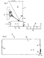
Fig. 1 zeigt schematisch und ausschnittweise eine Vorrichtung zum Herstellen von Betonsteinen in Seitenansicht und teilweise aufgeschnitten, -
Fig. 2 zeigt vergrößert einen Füllwagen der Vorrichtung vonFig. 1 . - Die Erfindung betrifft ein Verfahren und eine Vorrichtung zum Herstellen von Betonsteinen, bei dem aus einem Silo 1 Betonmörtel mittels einer Fördereinrichtung in ein Formwerkzeug 7 gefüllt wird und der in das Formwerkzeug 7 gefüllte Betonmörtel verdichtet und anschließend entformt wird, wobei die Masse des in das Formwerkzeug 7 gefüllten Betonmörtels zunächst oberseitig abgerollt und danach verdichtet wird. Die Fördereinrichtung kann ein Förderband oder ein verfahrbarer Füllwagen sein. Die Fördereinrichtung ist unter dem Auslauf des Silos 1 angeordnet zum Fördern von Betonmörtel zu einem Formwerkzeug, wodurch dieses aufgefüllt wird. Das in
Fig.1 dargestellte und nachfolgend beschriebene Ausführungsbeispiel verwendet als Fördereinrichtung einen Füllwagen. - Die in
Fig. 1 dargestellte Vorrichtung zum Herstellen von Betonsteinen umfasst einen Silo 1 mit mindestens einem nach unten trichterförmig zulaufenden Aufnahmeraum 2 für Betonmörtel. Der Aufnahmeraum 2 besitzt unterseitig eine am Silo 1 angelenkte, verschwenkbare Klappe 3 zum Öffnen des Aufnahmeraums 2 zu einem oben und unten offenen Füllwagen 4 hin. Der Füllwagen 4 ist über ein Tischblech 5 zwischen einer Stellung unter dem Auslauf oder Auslass des Silos 1 und einer Stellung über einem auf einer Fertigungsunterlage 6 befindlichen Formwerkzeug 7 für Betonsteine verfahrbar. Die Klappe 3 lässt sich beispielsweise jeweils über einen hydraulischen - oder wie dargestellt - elektromotorischen, ein Gestänge umfassenden Antrieb 8 in eine Offenstellung verschwenken, so dass in dem Aufnahmeraum 2 enthaltener, erdfeuchter Betonmörtel in den Füllwagen 4 fallen kann. - Der Füllwagen 4 besitzt einen Aufnahmeraum 10, der von einer Rahmenwandung umgeben ist. In seiner Verfahrrichtung, die mittels eines Doppelpfeils angezeigt ist, weist die Rahmenwandung Seitenwände 11, 12 auf. Mittels eines nicht gezeigten Antriebs ist Füllwagen 4 zwischen einer Befüllposition unterhalb des Silos 1 und einer Abgabeposition oberhalb des Formwerkzeuges 7 vorwärts und rückwärts verfahrbar. Der Füllwagen 4 kann dabei von einer ebenfalls nicht gezeigten, vorzugsweise beidseitig des Füllwagens 4 angeordneten, Horizontalführung geführt werden. Die Seitenwände 11, 12 bilden insoweit endseitige Begrenzungswände des Füllwagens 4 bei seiner Vorwärtsfahrt von dem Silo 1 zum Formwerkzeug 7 und seiner Rückwärtsfahrt von dem Formwerkzeug 7 zum Silo 1.
- Das Formwerkzeug 7 umfasst eine Form 9 mit einer wählbaren Anzahl Trennwände 14 zur Herstellung mehrerer Betonsteine mit einer Form 9. Zum Befüllen der Form 9 wird aus dem Silo 1 Betonmörtel in den Aufnahmeraum 10 des Füllwagens 4 gefüllt. Der mit Betonmörtel gefüllte Füllwagen 4 wird über das Formwerkzeug 7 verfahren. Durch den offenen Boden des Füllwagens 4 fällt der im Füllwagen 4 befindliche Betonmörtel in die Form 9. Die Abmessungen des Füllwagens 4 sind an die Abmessungen der Form 9 angepasst, damit die Form 9 vollständig befüllt wird. Der entleerte Füllwagen 4 wird danach in seine Stellung unter dem Auslauf des Silos 1 zurückgefahren.
- Die Masse des in das Formwerkzeug 7 gefüllten Betonmörtels wird oberseitig behandelt, bevor der Betonmörtel in der Form 9 verdichtet wird. Mittels einer Rolle 13 wird die Masse des Betonmörtels in dem Formwerkzeug 7 abgerollt. Die Rollenachse dieser Rolle 13 liegt vorzugsweise quer zum Verfahrweg des Füllwagens 4. Die Rolle 13 kann als separate Rolle geführt sein, beispielsweise an einem Gestänge.
- Gemäß
Fig. 1 ist die Rolle 13 an dem Füllwagen 4 angeordnet und bildet ein unteres Ende der einen Seitenwand 11 des Füllwagens 4, die beim Zurückverfahren des Füllwagens 4 eine hintere Seitenwand 11 bildet. Die Rolle 13 kann höhenverstellbar angeordnet sein und ist vorzugsweise so positioniert, dass sie bei dem Verfahren des Füllwagens 4 von der Stellung unterhalb des Silos 1 in Richtung Formwerkzeug 7 auf dem Tischblech 5 läuft und damit die Höhe der Bodenkante des Füllwagens 4 annimmt. Ferner ist die Positionierung der Rolle 13 derart gewählt, dass diese auf der Masse des in das Formwerkzeug 7 gefüllten Betonmörtels abrollt und sich dabei vorzugsweise über die gesamte Breite der Form 9 erstreckt, um eine gleichmäßige Oberfläche des eingefüllten Betonmörtels zu erhalten. - Die Rolle 13 kann nach Art eines Nudelholzes als druckbelastbare Walze ausgebildet sein, wozu eine Druckfederlagerung vorgesehen sein kann. Die Rolle 13, die zur Auflage auf dem Betonmörtel in dem Formwerkzeug 7 gelangt, überrollt dann die Oberfläche des Betonmörtels in dem Formwerkzeug 7 mit einer bestimmten Andruckkraft. Die Rolle 13 weist vorzugsweise eine harte und glatte Oberfläche auf und besteht dazu vorzugsweise aus Metall oder Kunststoff. Die Rolle 13 kann freilaufend angeordnet sein und erhält dann eine Umdrehungsgeschwindigkeit, die bei Reibung auf dem Betonmörtel abhängt von einer Fahrgeschwindigkeit des Füllwagens 4 oder einer Vorrichtung zur translatorischen Bewegung der Rolle 13 gegenüber dem Formwerkzeug 7.
- Die Rolle 13 ist mit einer wählbaren Umdrehungsgeschwindigkeit antreibbar. Diese Umdrehungsgeschwindigkeit der Rolle 13 ist in Bezug auf eine Fahrgeschwindigkeit des Füllwagens 4 einstellbar. Die Oberfläche der Rolle 13 kann mit einer Antihaftbeschichtung versehen sein. Die Oberfläche der Rolle 13 kann auch strukturiert sein.
- Dadurch, dass die Rolle 13 über den Betonmörtel rollt, wird eine gleichmäßige Glättung der Oberfläche erreicht. Ein Anhaften des insbesondere feuchten Betonmörtels an der Rolle 13 kann vermieden werden. Die Glättung ist somit unabhängig von der Feuchte des Betonmörtels durchführbar. Dadurch ermöglicht das erfindungsgemäße Verfahren eine gleichmäßigere Struktur der Steinoberfläche, insbesondere bei großformatigen Steinen.
- Schließlich kann auch durch eine Veränderung des Drehsinns der Rolle 13 die Richtung verändert werden, in welche der Betonmörtel gepresst wird. Auch ist es durch einen Antrieb möglich, dass die Rolle weder eine positive noch eine negative Relativgeschwindigkeit in Bezug auf die Verfahrgeschwindigkeit des Füllwagens 4 erreicht, sondern eben genau stillsteht. Auf diese Weise ist eine große Variabilität der Befüllung und Glättung bei großer Gleichmäßigkeit gegeben.
- Zweckmäßigerweise ist der Abstand der Rolle 13 von den Trennwänden 14 des Formwerkzeugs 7 veränderbar. So kann eine weitere Variation der Füllhöhe erreicht werden. Auf diese Weise ist das Volumen des nach dem Befüllvorgangs zu verdichtenden Betonmörtels sehr variabel.
- Gemäß der vorliegenden Erfindung umfasst ein Verfahren zum Herstellen von Betonsteinen folgende Schritte. Aus einem Silo 1 wird Betonmörtel in einen Aufnahmeraum 10 eines Füllwagens 4 gefüllt. Der Füllwagen 4 wird bis über ein Formwerkzeug 7 für die Betonsteine verfahren und das Formwerkzeug 7 wird mit Betonmörtel aus dem Füllwagen 4 aufgefüllt. Danach wird der Füllwagen 4 zurückverfahren, und der in das Formwerkzeug 7 gefüllte Betonmörtel wird verdichtet und anschließend entformt. Erfindungsgemäß ist dabei vorgesehen, dass die Masse des in das Formwerkzeug 7 gefüllten Betonmörtels erst oberseitig abgerollt und danach verdichtet wird. Das Abrollen kann mit einer Rollachse quer zum Verfahrweg des Füllwagens 4 durchgeführt werden. Das Abrollen wird beim Zurückverfahren des Füllwagens 4 ausgeführt. Das Abrollen kann als druckbelastetes Abwälzen ausgeführt werden. Zum Abrollen kann eine Rolle 13 mit einer harten und glatten Oberfläche verwendet werden. Das Abrollen erfolgt mit einer Differenzgeschwindigkeit zwischen einer Rolle 13 und dem Füllwagen 4. Die Umdrehungsgeschwindigkeit einer Rolle 13 kann zum Abrollen höher gewählt werden als eine Fahrgeschwindigkeit des Füllwagens 4. Die Umdrehungsgeschwindigkeit einer Rolle 13 zum Abrollen kann niedriger gewählt werden als eine Fahrgeschwindigkeit des Füllwagens 4. Das Abrollen kann mit einer variablen Spaltbreite eines Kontaktbereiches zwischen der Rolle 13 und der Masse des Betonmörtels durchgeführt werden.
Claims (12)
- Verfahren zum Herstellen von Betonsteinen, bei dem aus einem Silo (1) Betonmörtel mittels eines oben und unten offenen Füllwagens (4) in ein Formwerkzeug (7) gefüllt wird und der in das Formwerkzeug (7) gefüllte Betonmörtel verdichtet und anschließend entformt wird, und die Masse des in das Formwerkzeug (7) gefüllten Betonmörtels zunächst oberseitig mit einer Rolle (13) abgerollt und danach verdichtet wird, dadurch gekennzeichnet, dass das Abrollen beim Zurückfahren des Füllwagens (4) ausgeführt wird mit einer Rolle (13), die ein unteres Ende einer Seitenwand (11) des Füllwagens (4) bildet, die beim Zurückfahren des Füllwagens (4) eine hintere Seitenwand (11) bildet, die Rolle (13) dabei mit einer wählbaren Umdrehungsgeschwindigkeit angetrieben wird, und das Abrollen mit einer Differenzgeschwindigkeit zwischen der Rolle (13) und dem Füllwagen (4) erfolgt.
- Verfahren nach Anspruch 1, dadurch gekennzeichnet, dass das Abrollen mit einer Rollachse quer zum Verfahrweg des Füllwagens (4) durchgeführt wird.
- Verfahren nach Anspruch 1 oder 2, dadurch gekennzeichnet, dass die Umdrehungsgeschwindigkeit der Rolle (13) zum Abrollen höher gewählt wird als eine Fahrgeschwindigkeit des Füllwagens (4).
- Verfahren nach Anspruch 1 oder 2, dadurch gekennzeichnet, dass die Umdrehungsgeschwindigkeit der Rolle (13) zum Abrollen niedriger gewählt wird als eine Fahrgeschwindigkeit des Füllwagens (4).
- Verfahren nach einem der Ansprüche 1 bis 4, dadurch gekennzeichnet, dass das Abrollen als druckbelastetes Abwälzen ausgeführt wird.
- Verfahren nach einem der Ansprüche 1 bis 5, wobei die Rolle (13) zur Ausbildung einer harten und glatten Oberfläche aus Metall besteht.
- Verfahren nach einem der Ansprüche 1 bis 5, dadurch gekennzeichnet, dass die Rolle (13) zur Ausbildung einer harten und glatten Oberfläche aus Kunststoff besteht.
- Verfahren nach einem der Ansprüche 1 bis 7, dadurch gekennzeichnet, dass das Abrollen mit einer variablen Spaltbreite eines Kontaktbereiches zwischen der Rolle (13) und der Masse des Betonmörtels durchgeführt wird.
- Vorrichtung zum Herstellen von Betonsteinen mit einem Silo (1) mit einem unterseitigen Auslauf für Betonmörtel und einem unter dem Auslauf des Silos (1) angeordneten oben und unten offenen Füllwagen (4) zum Fördern von Betonmörtel zu einem Formwerkzeug (7), wobei eine Rolle (13) mit einer gegenüber dem Formwerkzeug (7) verfahrbar geführten Rollenachse zum Abrollen der aufgefüllten Masse in dem Formwerkzeug (7) vorgesehen ist, dadurch gekennzeichnet, dass die Rolle (13) ein unteres Ende einer Seitenwand (11) des Füllwagens (4) bildet, die beim Zurückfahren des Füllwagens (4) eine hintere Seitenwand (11) bildet, die Rolle (13) dabei mit einer wählbaren Umdrehungsgeschwindigkeit antreibbar ist, und das Abrollen mit einer Differenzgeschwindigkeit zwischen der Rolle (13) und dem Füllwagen (4) erfolgt.
- Vorrichtung nach Anspruch 9, dadurch gekennzeichnet, dass die Rollenachse quer zum Verfahrweg des Füllwagens (4) verfahrbar geführt ist.
- Vorrichtung nach Anspruch 9 oder 10, dadurch gekennzeichnet, dass die Rolle (13) als druckbelastbare Walze ausgebildet ist.
- Vorrichtung nach einem der Ansprüche 9 bis 11, dadurch gekennzeichnet, dass die Rolle (13) druckfedergelagert angeordnet ist.
Priority Applications (1)
| Application Number | Priority Date | Filing Date | Title |
|---|---|---|---|
| PL13002622T PL2628581T3 (pl) | 2007-10-11 | 2008-10-09 | Sposób i urządzenie do wytwarzania bloczków betonowych |
Applications Claiming Priority (2)
| Application Number | Priority Date | Filing Date | Title |
|---|---|---|---|
| DE102007048694A DE102007048694A1 (de) | 2007-10-11 | 2007-10-11 | Verfahren und Vorrichtung zum Herstellen von Betonsteinen |
| EP08802840.2A EP2197642B1 (de) | 2007-10-11 | 2008-10-09 | Verfahren und vorrichtung zum herstellen von betonsteinen |
Related Parent Applications (2)
| Application Number | Title | Priority Date | Filing Date |
|---|---|---|---|
| EP08802840.2 Division | 2008-10-09 | ||
| EP08802840.2A Division EP2197642B1 (de) | 2007-10-11 | 2008-10-09 | Verfahren und vorrichtung zum herstellen von betonsteinen |
Publications (2)
| Publication Number | Publication Date |
|---|---|
| EP2628581A1 EP2628581A1 (de) | 2013-08-21 |
| EP2628581B1 true EP2628581B1 (de) | 2014-04-09 |
Family
ID=40458660
Family Applications (2)
| Application Number | Title | Priority Date | Filing Date |
|---|---|---|---|
| EP08802840.2A Active EP2197642B1 (de) | 2007-10-11 | 2008-10-09 | Verfahren und vorrichtung zum herstellen von betonsteinen |
| EP13002622.2A Active EP2628581B1 (de) | 2007-10-11 | 2008-10-09 | Verfahren und Vorrichtung zum Herstellen von Betonsteinen |
Family Applications Before (1)
| Application Number | Title | Priority Date | Filing Date |
|---|---|---|---|
| EP08802840.2A Active EP2197642B1 (de) | 2007-10-11 | 2008-10-09 | Verfahren und vorrichtung zum herstellen von betonsteinen |
Country Status (6)
| Country | Link |
|---|---|
| EP (2) | EP2197642B1 (de) |
| DE (2) | DE102007048694A1 (de) |
| DK (2) | DK2628581T3 (de) |
| ES (2) | ES2466220T3 (de) |
| PL (2) | PL2197642T3 (de) |
| WO (1) | WO2009049815A2 (de) |
Cited By (1)
| Publication number | Priority date | Publication date | Assignee | Title |
|---|---|---|---|---|
| CN111516100A (zh) * | 2020-04-23 | 2020-08-11 | 刘海信 | 一种粉笔模具的石膏自动刮平装置 |
Families Citing this family (5)
| Publication number | Priority date | Publication date | Assignee | Title |
|---|---|---|---|---|
| CN109834978B (zh) * | 2019-03-19 | 2021-04-16 | 南通中液液压机有限公司 | 一种多台阶多层干粉制品全自动成型液压机送料装置 |
| CN111231086A (zh) * | 2020-02-28 | 2020-06-05 | 山东建筑大学 | 一种混凝土预制构件生产设备 |
| CN111761966B (zh) * | 2020-06-09 | 2022-01-11 | 江苏中腾石英材料科技股份有限公司 | 一种粉笔生产用自动化模具注浆设备 |
| CN112265107B (zh) * | 2020-10-26 | 2022-07-22 | 乐陵市瑞林建材有限公司 | 一种砌块浇注成型系统 |
| CN112372836A (zh) * | 2020-10-28 | 2021-02-19 | 安徽绿风环保节能材料有限公司 | 一种加气混凝土桨料搅拌浇筑装置 |
Family Cites Families (13)
| Publication number | Priority date | Publication date | Assignee | Title |
|---|---|---|---|---|
| DE138743C (de) * | ||||
| DE1066469B (de) * | ||||
| DE1683901C3 (de) * | 1967-05-19 | 1975-09-11 | Maschinenfabrik Schleis Kg, Zwammerdam (Niederlande) | Vorrichtung zum Herstellen von Fertigteilbauelementen |
| DE1941546A1 (de) * | 1969-08-14 | 1971-02-25 | Robert Forwick | Vorrichtung zum Herstellen von Kunststeinen |
| DE3809162A1 (de) * | 1988-03-18 | 1989-09-28 | Braas & Co Gmbh | Vorrichtung zur herstellung mehrschichtiger betondachsteine |
| SU1597271A1 (ru) * | 1988-11-21 | 1990-10-07 | Киевский Инженерно-Строительный Институт | Устройство дл формовани изделий из бетонных смесей |
| ES2015202A6 (es) * | 1989-08-10 | 1990-08-01 | Perez Tena Francisco | Maquina para el autollenado de moldes con hormigones semifluidos u o- tros. |
| JPH0911211A (ja) | 1995-06-30 | 1997-01-14 | Kawai Tekko Kk | コンクリート材の均し装置 |
| JP3699231B2 (ja) * | 1997-01-27 | 2005-09-28 | クボタ松下電工外装株式会社 | 無機質板の製造方法 |
| IT1294941B1 (it) * | 1997-08-01 | 1999-04-23 | Ariostea S P A | Sistema di caricamento degli stampi delle presse per la formatura di piastrelle e relativi mezzi di attuazione. |
| IT1311905B1 (it) * | 1999-04-02 | 2002-03-20 | Martinelli Ettore Srl | Pressa per la produzione di piastrelle con dispositivo di caricamentoa doppio strato. |
| DE10339143B4 (de) | 2003-08-26 | 2005-10-13 | Hess Maschinenfabrik Gmbh & Co. Kg | Verfahren und Vorrichtung zum Herstellen mehrfarbiger Betonsteine |
| DE102004009382B3 (de) | 2004-02-26 | 2005-10-27 | Hess Maschinenfabrik Gmbh & Co. Kg | Verfahren und Vorrichtung zum Herstellen von Betonsteinen |
-
2007
- 2007-10-11 DE DE102007048694A patent/DE102007048694A1/de not_active Withdrawn
-
2008
- 2008-10-09 PL PL08802840T patent/PL2197642T3/pl unknown
- 2008-10-09 DK DK13002622.2T patent/DK2628581T3/da active
- 2008-10-09 DE DE202008017871U patent/DE202008017871U1/de not_active Expired - Lifetime
- 2008-10-09 EP EP08802840.2A patent/EP2197642B1/de active Active
- 2008-10-09 ES ES13002622.2T patent/ES2466220T3/es active Active
- 2008-10-09 PL PL13002622T patent/PL2628581T3/pl unknown
- 2008-10-09 ES ES08802840.2T patent/ES2452466T3/es active Active
- 2008-10-09 DK DK08802840.2T patent/DK2197642T3/da active
- 2008-10-09 EP EP13002622.2A patent/EP2628581B1/de active Active
- 2008-10-09 WO PCT/EP2008/008522 patent/WO2009049815A2/de not_active Ceased
Cited By (2)
| Publication number | Priority date | Publication date | Assignee | Title |
|---|---|---|---|---|
| CN111516100A (zh) * | 2020-04-23 | 2020-08-11 | 刘海信 | 一种粉笔模具的石膏自动刮平装置 |
| CN111516100B (zh) * | 2020-04-23 | 2021-10-08 | 台州友驿科技有限公司 | 一种粉笔模具的石膏自动刮平装置 |
Also Published As
| Publication number | Publication date |
|---|---|
| ES2452466T3 (es) | 2014-04-01 |
| EP2197642B1 (de) | 2013-12-11 |
| EP2197642A2 (de) | 2010-06-23 |
| DK2628581T3 (da) | 2014-07-07 |
| PL2197642T3 (pl) | 2014-07-31 |
| WO2009049815A2 (de) | 2009-04-23 |
| WO2009049815A3 (de) | 2009-06-04 |
| DE202008017871U1 (de) | 2010-09-16 |
| PL2628581T3 (pl) | 2014-09-30 |
| ES2466220T3 (es) | 2014-06-09 |
| DK2197642T3 (da) | 2014-03-10 |
| DE102007048694A1 (de) | 2009-04-23 |
| EP2628581A1 (de) | 2013-08-21 |
Similar Documents
| Publication | Publication Date | Title |
|---|---|---|
| DE69817279T2 (de) | Vorrichtung zur Füllung der Formen in Pressen zur Herstellung von Fliesen und Ausführungsmittel dafür | |
| DE69516640T2 (de) | Verfahren und Vorrichtung zur Herstellung von Getreideaggregaten auf industrieller Basis | |
| EP2197642B1 (de) | Verfahren und vorrichtung zum herstellen von betonsteinen | |
| DE202010000882U1 (de) | Vorrichtung zum Beschicken von Formen zum Herstellen von Betonplatten oder Betonsteinen | |
| WO2009003507A1 (de) | Befüllungseinrichtung zum befüllen von formwerkzeugen mit schüttfähigem formmaterial | |
| EP2055457B1 (de) | Verfahren zum Herstellen eines Bausteins aus Beton und Vorrichtung zur Durchfuehrung des Verfahrens | |
| DE202020102685U1 (de) | Vorrichtung zum Herstellen von unter Verwendung eines formbaren und aushärtenden Baumaterials errichteten Streckenbauwerken | |
| DE3101709A1 (de) | Verfahren und vorrichtung zur herstellung von verbundprofilen fuer fensterrahmen, tuerrahmen, fassadenkonstruktionen o.dgl. | |
| AT500460B1 (de) | Vorrichtung zum herstellen eines hohlbausteins aus einer hydraulisch aushärtenden, feuchten bausteinmasse | |
| DE102007012593B4 (de) | Vorrichtung zum Beschicken von Formen zum Herstellen von Betonplatten oder Betonsteinen | |
| DE552729C (de) | Beschickungsvorrichtung fuer Toepfereimaschinen und Verfahren zu deren Bedienung | |
| DE3311965C2 (de) | Vorrichtung zur Herstellung von Betonplatten | |
| DE2524623A1 (de) | Vorrichtung zum formen der oberflaeche einer schicht aus formbarem werkstoff | |
| DE1810128A1 (de) | Verfahren und Einrichtung zum Herstellen von Betonelementen insbesondere von Betonpflastersteinen | |
| DE2225939C3 (de) | Verfahren und Vorrichtung zur mechanischen Herstellung von sogenannten Handformsteinen | |
| DE3724641A1 (de) | Verfahren und vorrichtung zur maschinellen herstellung eines waermedaemmenden leichtbeton-mauersteins | |
| EP1213411B1 (de) | Vorrichtung und Verfahren zum Aufbringen von Dünnbettmörtel | |
| DE2548956C3 (de) | Verfahren und Formmaschine zur Herstellung einer Gießereiform | |
| DE102019117141A1 (de) | Verfahren und Vorrichtungen zur Herstellung von Betonsteinen und Betonplatten | |
| EP4703109A1 (de) | Anlage und verfahren zur herstellung von betonsteinen mit farbdekor | |
| DE102007062468B3 (de) | Überziehmaschine für Süßwarenstücke mit einer Bodenwallstation | |
| DE2152124B2 (de) | Maschine zum Herstellen länglicher Betonbauelemente | |
| EP2286978A2 (de) | Vorrichtung sowie Verfahren zum Zuführen von Preforms | |
| DE1584732C3 (de) | Vorrichtung zum Herstellen von Betondachpfannen | |
| DE2447541C3 (de) | Anlage zur Herstellung von Filzrohlingen |
Legal Events
| Date | Code | Title | Description |
|---|---|---|---|
| PUAI | Public reference made under article 153(3) epc to a published international application that has entered the european phase |
Free format text: ORIGINAL CODE: 0009012 |
|
| 17P | Request for examination filed |
Effective date: 20130517 |
|
| AC | Divisional application: reference to earlier application |
Ref document number: 2197642 Country of ref document: EP Kind code of ref document: P |
|
| AK | Designated contracting states |
Kind code of ref document: A1 Designated state(s): AT BE BG CH CY CZ DE DK EE ES FI FR GB GR HR HU IE IS IT LI LT LU LV MC MT NL NO PL PT RO SE SI SK TR |
|
| RIN1 | Information on inventor provided before grant (corrected) |
Inventor name: BERGHAMMER, HANS GEORG Inventor name: GRAF, TORSTEN |
|
| GRAP | Despatch of communication of intention to grant a patent |
Free format text: ORIGINAL CODE: EPIDOSNIGR1 |
|
| INTG | Intention to grant announced |
Effective date: 20131206 |
|
| GRAS | Grant fee paid |
Free format text: ORIGINAL CODE: EPIDOSNIGR3 |
|
| GRAA | (expected) grant |
Free format text: ORIGINAL CODE: 0009210 |
|
| AC | Divisional application: reference to earlier application |
Ref document number: 2197642 Country of ref document: EP Kind code of ref document: P |
|
| AK | Designated contracting states |
Kind code of ref document: B1 Designated state(s): AT BE BG CH CY CZ DE DK EE ES FI FR GB GR HR HU IE IS IT LI LT LU LV MC MT NL NO PL PT RO SE SI SK TR |
|
| REG | Reference to a national code |
Ref country code: GB Ref legal event code: FG4D Free format text: NOT ENGLISH |
|
| REG | Reference to a national code |
Ref country code: CH Ref legal event code: EP Ref country code: AT Ref legal event code: REF Ref document number: 661088 Country of ref document: AT Kind code of ref document: T Effective date: 20140415 |
|
| REG | Reference to a national code |
Ref country code: DE Ref legal event code: R096 Ref document number: 502008011587 Country of ref document: DE Effective date: 20140515 |
|
| REG | Reference to a national code |
Ref country code: IE Ref legal event code: FG4D Free format text: LANGUAGE OF EP DOCUMENT: GERMAN |
|
| REG | Reference to a national code |
Ref country code: ES Ref legal event code: FG2A Ref document number: 2466220 Country of ref document: ES Kind code of ref document: T3 Effective date: 20140609 |
|
| REG | Reference to a national code |
Ref country code: DK Ref legal event code: T3 Effective date: 20140701 |
|
| REG | Reference to a national code |
Ref country code: NL Ref legal event code: VDEP Effective date: 20140409 |
|
| REG | Reference to a national code |
Ref country code: LT Ref legal event code: MG4D |
|
| REG | Reference to a national code |
Ref country code: PL Ref legal event code: T3 |
|
| REG | Reference to a national code |
Ref country code: DE Ref legal event code: R082 Ref document number: 502008011587 Country of ref document: DE Representative=s name: SPARING - ROEHL - HENSELER, DE |
|
| RAP2 | Party data changed (patent owner data changed or rights of a patent transferred) |
Owner name: HESS GROUP GMBH |
|
| PG25 | Lapsed in a contracting state [announced via postgrant information from national office to epo] |
Ref country code: GR Free format text: LAPSE BECAUSE OF FAILURE TO SUBMIT A TRANSLATION OF THE DESCRIPTION OR TO PAY THE FEE WITHIN THE PRESCRIBED TIME-LIMIT Effective date: 20140710 Ref country code: NO Free format text: LAPSE BECAUSE OF FAILURE TO SUBMIT A TRANSLATION OF THE DESCRIPTION OR TO PAY THE FEE WITHIN THE PRESCRIBED TIME-LIMIT Effective date: 20140709 Ref country code: BG Free format text: LAPSE BECAUSE OF FAILURE TO SUBMIT A TRANSLATION OF THE DESCRIPTION OR TO PAY THE FEE WITHIN THE PRESCRIBED TIME-LIMIT Effective date: 20140709 Ref country code: IS Free format text: LAPSE BECAUSE OF FAILURE TO SUBMIT A TRANSLATION OF THE DESCRIPTION OR TO PAY THE FEE WITHIN THE PRESCRIBED TIME-LIMIT Effective date: 20140809 Ref country code: NL Free format text: LAPSE BECAUSE OF FAILURE TO SUBMIT A TRANSLATION OF THE DESCRIPTION OR TO PAY THE FEE WITHIN THE PRESCRIBED TIME-LIMIT Effective date: 20140409 Ref country code: LT Free format text: LAPSE BECAUSE OF FAILURE TO SUBMIT A TRANSLATION OF THE DESCRIPTION OR TO PAY THE FEE WITHIN THE PRESCRIBED TIME-LIMIT Effective date: 20140409 Ref country code: FI Free format text: LAPSE BECAUSE OF FAILURE TO SUBMIT A TRANSLATION OF THE DESCRIPTION OR TO PAY THE FEE WITHIN THE PRESCRIBED TIME-LIMIT Effective date: 20140409 |
|
| REG | Reference to a national code |
Ref country code: DE Ref legal event code: R082 Ref document number: 502008011587 Country of ref document: DE Representative=s name: SPARING - ROEHL - HENSELER, DE Effective date: 20141006 Ref country code: DE Ref legal event code: R081 Ref document number: 502008011587 Country of ref document: DE Owner name: HESS GROUP GMBH, DE Free format text: FORMER OWNER: HESS MASCHINENFABRIK GMBH & CO. KG, 57299 BURBACH, DE Effective date: 20141006 |
|
| PG25 | Lapsed in a contracting state [announced via postgrant information from national office to epo] |
Ref country code: LV Free format text: LAPSE BECAUSE OF FAILURE TO SUBMIT A TRANSLATION OF THE DESCRIPTION OR TO PAY THE FEE WITHIN THE PRESCRIBED TIME-LIMIT Effective date: 20140409 Ref country code: SE Free format text: LAPSE BECAUSE OF FAILURE TO SUBMIT A TRANSLATION OF THE DESCRIPTION OR TO PAY THE FEE WITHIN THE PRESCRIBED TIME-LIMIT Effective date: 20140409 Ref country code: HR Free format text: LAPSE BECAUSE OF FAILURE TO SUBMIT A TRANSLATION OF THE DESCRIPTION OR TO PAY THE FEE WITHIN THE PRESCRIBED TIME-LIMIT Effective date: 20140409 |
|
| PG25 | Lapsed in a contracting state [announced via postgrant information from national office to epo] |
Ref country code: PT Free format text: LAPSE BECAUSE OF FAILURE TO SUBMIT A TRANSLATION OF THE DESCRIPTION OR TO PAY THE FEE WITHIN THE PRESCRIBED TIME-LIMIT Effective date: 20140811 |
|
| REG | Reference to a national code |
Ref country code: DE Ref legal event code: R097 Ref document number: 502008011587 Country of ref document: DE |
|
| PG25 | Lapsed in a contracting state [announced via postgrant information from national office to epo] |
Ref country code: EE Free format text: LAPSE BECAUSE OF FAILURE TO SUBMIT A TRANSLATION OF THE DESCRIPTION OR TO PAY THE FEE WITHIN THE PRESCRIBED TIME-LIMIT Effective date: 20140409 Ref country code: RO Free format text: LAPSE BECAUSE OF FAILURE TO SUBMIT A TRANSLATION OF THE DESCRIPTION OR TO PAY THE FEE WITHIN THE PRESCRIBED TIME-LIMIT Effective date: 20140409 Ref country code: SK Free format text: LAPSE BECAUSE OF FAILURE TO SUBMIT A TRANSLATION OF THE DESCRIPTION OR TO PAY THE FEE WITHIN THE PRESCRIBED TIME-LIMIT Effective date: 20140409 Ref country code: CZ Free format text: LAPSE BECAUSE OF FAILURE TO SUBMIT A TRANSLATION OF THE DESCRIPTION OR TO PAY THE FEE WITHIN THE PRESCRIBED TIME-LIMIT Effective date: 20140409 |
|
| PLBE | No opposition filed within time limit |
Free format text: ORIGINAL CODE: 0009261 |
|
| STAA | Information on the status of an ep patent application or granted ep patent |
Free format text: STATUS: NO OPPOSITION FILED WITHIN TIME LIMIT |
|
| 26N | No opposition filed |
Effective date: 20150112 |
|
| REG | Reference to a national code |
Ref country code: DE Ref legal event code: R097 Ref document number: 502008011587 Country of ref document: DE Effective date: 20150112 |
|
| PG25 | Lapsed in a contracting state [announced via postgrant information from national office to epo] |
Ref country code: MC Free format text: LAPSE BECAUSE OF FAILURE TO SUBMIT A TRANSLATION OF THE DESCRIPTION OR TO PAY THE FEE WITHIN THE PRESCRIBED TIME-LIMIT Effective date: 20140409 Ref country code: LU Free format text: LAPSE BECAUSE OF FAILURE TO SUBMIT A TRANSLATION OF THE DESCRIPTION OR TO PAY THE FEE WITHIN THE PRESCRIBED TIME-LIMIT Effective date: 20141009 |
|
| REG | Reference to a national code |
Ref country code: CH Ref legal event code: PL |
|
| GBPC | Gb: european patent ceased through non-payment of renewal fee |
Effective date: 20141009 |
|
| PG25 | Lapsed in a contracting state [announced via postgrant information from national office to epo] |
Ref country code: BE Free format text: LAPSE BECAUSE OF NON-PAYMENT OF DUE FEES Effective date: 20141031 |
|
| REG | Reference to a national code |
Ref country code: IE Ref legal event code: MM4A |
|
| PG25 | Lapsed in a contracting state [announced via postgrant information from national office to epo] |
Ref country code: LI Free format text: LAPSE BECAUSE OF NON-PAYMENT OF DUE FEES Effective date: 20141031 Ref country code: SI Free format text: LAPSE BECAUSE OF FAILURE TO SUBMIT A TRANSLATION OF THE DESCRIPTION OR TO PAY THE FEE WITHIN THE PRESCRIBED TIME-LIMIT Effective date: 20140409 Ref country code: GB Free format text: LAPSE BECAUSE OF NON-PAYMENT OF DUE FEES Effective date: 20141009 Ref country code: CH Free format text: LAPSE BECAUSE OF NON-PAYMENT OF DUE FEES Effective date: 20141031 |
|
| REG | Reference to a national code |
Ref country code: AT Ref legal event code: PC Ref document number: 661088 Country of ref document: AT Kind code of ref document: T Owner name: HESS GROUP GMBH, DE Effective date: 20150903 |
|
| REG | Reference to a national code |
Ref country code: FR Ref legal event code: PLFP Year of fee payment: 8 |
|
| PG25 | Lapsed in a contracting state [announced via postgrant information from national office to epo] |
Ref country code: IE Free format text: LAPSE BECAUSE OF NON-PAYMENT OF DUE FEES Effective date: 20141009 |
|
| PG25 | Lapsed in a contracting state [announced via postgrant information from national office to epo] |
Ref country code: CY Free format text: LAPSE BECAUSE OF FAILURE TO SUBMIT A TRANSLATION OF THE DESCRIPTION OR TO PAY THE FEE WITHIN THE PRESCRIBED TIME-LIMIT Effective date: 20140409 |
|
| PG25 | Lapsed in a contracting state [announced via postgrant information from national office to epo] |
Ref country code: HU Free format text: LAPSE BECAUSE OF FAILURE TO SUBMIT A TRANSLATION OF THE DESCRIPTION OR TO PAY THE FEE WITHIN THE PRESCRIBED TIME-LIMIT; INVALID AB INITIO Effective date: 20081009 Ref country code: MT Free format text: LAPSE BECAUSE OF FAILURE TO SUBMIT A TRANSLATION OF THE DESCRIPTION OR TO PAY THE FEE WITHIN THE PRESCRIBED TIME-LIMIT Effective date: 20140409 |
|
| REG | Reference to a national code |
Ref country code: FR Ref legal event code: PLFP Year of fee payment: 9 |
|
| REG | Reference to a national code |
Ref country code: FR Ref legal event code: PLFP Year of fee payment: 10 |
|
| REG | Reference to a national code |
Ref country code: FR Ref legal event code: PLFP Year of fee payment: 11 |
|
| P01 | Opt-out of the competence of the unified patent court (upc) registered |
Effective date: 20230525 |
|
| PGFP | Annual fee paid to national office [announced via postgrant information from national office to epo] |
Ref country code: PL Payment date: 20250925 Year of fee payment: 18 Ref country code: TR Payment date: 20250930 Year of fee payment: 18 |
|
| PGFP | Annual fee paid to national office [announced via postgrant information from national office to epo] |
Ref country code: AT Payment date: 20251022 Year of fee payment: 18 |
|
| PGFP | Annual fee paid to national office [announced via postgrant information from national office to epo] |
Ref country code: IT Payment date: 20251024 Year of fee payment: 18 Ref country code: DK Payment date: 20251027 Year of fee payment: 18 |
|
| PGFP | Annual fee paid to national office [announced via postgrant information from national office to epo] |
Ref country code: FR Payment date: 20251030 Year of fee payment: 18 |
|
| PGFP | Annual fee paid to national office [announced via postgrant information from national office to epo] |
Ref country code: ES Payment date: 20251210 Year of fee payment: 18 |
|
| PGFP | Annual fee paid to national office [announced via postgrant information from national office to epo] |
Ref country code: DE Payment date: 20251229 Year of fee payment: 18 |