EP2628552B1 - Dispositif de tri et de transport contrôlé - Google Patents
Dispositif de tri et de transport contrôlé Download PDFInfo
- Publication number
- EP2628552B1 EP2628552B1 EP20120008395 EP12008395A EP2628552B1 EP 2628552 B1 EP2628552 B1 EP 2628552B1 EP 20120008395 EP20120008395 EP 20120008395 EP 12008395 A EP12008395 A EP 12008395A EP 2628552 B1 EP2628552 B1 EP 2628552B1
- Authority
- EP
- European Patent Office
- Prior art keywords
- sorting
- objects
- transport
- aforementioned
- objects according
- Prior art date
- Legal status (The legal status is an assumption and is not a legal conclusion. Google has not performed a legal analysis and makes no representation as to the accuracy of the status listed.)
- Active
Links
Images


Classifications
-
- B—PERFORMING OPERATIONS; TRANSPORTING
- B03—SEPARATION OF SOLID MATERIALS USING LIQUIDS OR USING PNEUMATIC TABLES OR JIGS; MAGNETIC OR ELECTROSTATIC SEPARATION OF SOLID MATERIALS FROM SOLID MATERIALS OR FLUIDS; SEPARATION BY HIGH-VOLTAGE ELECTRIC FIELDS
- B03B—SEPARATING SOLID MATERIALS USING LIQUIDS OR USING PNEUMATIC TABLES OR JIGS
- B03B9/00—General arrangement of separating plant, e.g. flow sheets
- B03B9/06—General arrangement of separating plant, e.g. flow sheets specially adapted for refuse
-
- B—PERFORMING OPERATIONS; TRANSPORTING
- B07—SEPARATING SOLIDS FROM SOLIDS; SORTING
- B07C—POSTAL SORTING; SORTING INDIVIDUAL ARTICLES, OR BULK MATERIAL FIT TO BE SORTED PIECE-MEAL, e.g. BY PICKING
- B07C7/00—Sorting by hand only e.g. of mail
- B07C7/04—Apparatus or accessories for hand picking
Definitions
- the invention relates to a device for sorting and controlled conveyance of material groups to sort objects for recycling and waste disposal.
- sorting devices which can sometimes sort fully automatically waste products according to certain properties, in particular their constituents and recyclables. In order to be able to achieve particularly high levels of purity during sorting, it may be necessary to sort by hand. Especially with high throughput rates, the sorting for recyclables is sometimes very difficult.
- sorting aids from the household and hobby sector, for example, according to the US 5,117,982 A which allow individual beds of fractions but can not meet the required throughput rates, for example in a sorting plant.
- the object of the invention is to provide a device for sorting and controlled conveyors, with which a faster and more accurate sorting can be achieved.
- a device for sorting and controlled conveyance of by value groups to sorting objects a Sortiertribüne and at least one transport device, wherein the transport device has at least one partition, with which the transport path can be divided into at least two channels and at least one loading as a mechanical obstacle in transporting the objects from the transport path to a downstream fall distance.
- the objects are to be sorted according to material groups. On the one hand, this means, for example, that it is sorted according to whether the corresponding objects made of PET (polyethylene terephthalate) consist of PEHD (hard polyethylene) or of other plastics. It can also or additionally be sorted by color, for example, whether transparent, light PET bottles or dark colored PET bottles, white, green, etc. are present.
- PET polyethylene terephthalate
- PEHD hard polyethylene
- Each of these recyclable groups can be assigned to a channel.
- the presorting or actual sorting is automated.
- a wide variety of optical methods, X-ray methods or mechanical methods can be used.
- Corresponding sorting components are, for example, ballistic separators, sieve drums; However, as described, more specific determination methods such as optical methods or X-ray analyzes are basically used.
- these are in particular sorting systems for light packaging for example the sorting of plastic waste and lightweight packaging, films, bottles, smaller containers, etc., which are recyclable.
- Households collect such packaging waste mostly in the yellow bag or the so-called "RaWEG bag” or any containers that are connected to the dual system.
- a ballistic separator a mechanical pre-sorting into light and rolling heavy parts takes place first.
- an optical sorting can separate PET bottles and PET hollow bodies. Separation methods such as the sink-float separation can also be used. in which objects can be separated according to their specific weight. Such separation processes achieve purities of well over 90 percent.
- the sorted or pre-sorted objects are transported, for example, with conveyor belts.
- the re-sorting only makes a small contribution to the sorting on a percentage basis due to the already achieved high purity grades, this is sometimes very difficult, especially at high throughput rates.
- the sorting is particularly difficult, since the same amount of objects to be sorted is not always generated for the individual material groups. For example, a large amount of waste to be sorted may contain PET bottles, but only a small proportion of PEHD parts. Especially if objects are presorted into the wrong resource group simultaneously in several channels, the simultaneous resorting or re-sorting of these objects is correspondingly more difficult.
- At least one loading is arranged as a mechanical obstacle when conveying the objects from the transport path to the drop route between the transport path on which the presorted objects are brought in the direction of sorting turrets from which an operator takes over the re-sorting.
- the drawer can be advantageously used so that at the point where the operator takes over the re-sorting by hand, the objects are accumulated, so that the operator gains time to carry out a subsequent sorting conscientious.
- the transport device may in principle comprise a plurality of individual transport devices, such as a plurality of conveyor belts; but it may also be a single transport device, for example, a single conveyor belt, which is divisible by partitions in several sub-areas, so-called channels. Each channel can accordingly be assigned a resource group.
- the drawer can in principle be arranged so that it only serves as a Obstacle and not as a complete blockade, which means that the objects can initially accumulate, but from a certain amount forwarded.
- the device for sorting and controlled conveyance according to the invention can be used for all conceivable sorting operations, for example also for metal sorting.
- the drawer is adjusted with respect to its angle to the transport path of the transport device so that it has a different mechanical resistance in conveyed objects during transport opposes.
- the tray can also be designed as a chute, which allows a different speed depending on the angle of inclination.
- a passage opening may be present, so that the objects can finally reach the drop route via the passage opening.
- the passage opening is then bounded to one side by the tray, to another side by a boundary wall. The operator thereby has more time to perform the re-sorting operation, while if too many objects accumulate in this area of the tray, the objects can still pass through the opening to the drop zone, thus avoiding clogging.
- the drawer which adjoins the transport path via the transport device, is inclined upward, that is to say on the side on which the objects are conveyed, the drawer closes an angle of less than 180 ° with the conveyor belt (180 degrees).
- the loading itself forms a mechanical obstacle for the transported objects by their angle of attack, since they have to overcome this mechanical obstacle (against gravity) on further transport.
- the tray is designed as a chute, that is, it is inclined with respect to the transport path that on the side on which the objects are transported, the loading with the conveyor belt at an angle greater than 180 ° or includes on the side facing away from it, usually below the conveyor belt, an angle smaller 180 ° includes.
- the mechanical resistance is then formed on the one hand by the frictional resistance itself, which has the tray opposite the transported objects, on the other hand by the size of the opening, which is bounded on one side by the tray and forms the passage to the drop distance.
- this opening is barely larger than the average size of an object, then damming will easily occur, especially as objects tend to become wedged easily in the opening. Consequently, if the drawer is designed as a chute, the mechanical obstacle is mainly composed of the friction that the chute has with respect to the objects, the inclination angle of the chute and the size of the passage opening, which determines how quickly a jam can occur ,
- the question of whether a jam comes about, also influenced by how many objects at once reach the passage opening. If the passage opening, for example, slightly larger than the transported objects, then no jam will arise when objects pass successively to the passage opening without z. B. to stand diagonally and to wedge.
- the conveyed objects are usually present on the conveyor belt as accumulation and as a batch.
- individual objects that are separate from such clusters can usually be detected easily and quickly. The subsequent sorting can thus be substantially facilitated.
- the tray is rotatably mounted and adjustable in terms of their angle to the transport path and / or the boundary wall of the drop distance.
- the mechanical Widerstrand or the mechanical obstacle can be adjusted when moving the objects.
- the mechanical obstacle can also be set so small that the transported objects are transported practically without noticeable resistance on. If the drawer is designed, for example, as a chute, the chute can in principle also be set almost vertically downwards, so that the objects reach the drop path practically directly.
- the passage opening can be increased or decreased by tilting the tray.
- the larger the passage opening the easier the objects can be fall through. If the load z. B. tilted away down (slide), is an enlargement of the passage regularly associated with a steeper course of the slide.
- the chute can also be adjusted so that the friction causes the objects to be braked practically completely on the chute after the transport device.
- the chute itself does not include a machine conveyor such as a conveyor belt. Depending on the friction or mechanical resistance, in principle, the conveyed objects, which reach the drawer after the transport device, can be braked so that they remain lying on the drawer.
- This adjustment which allows a rotatable storage of the load, offers, among other things, the advantage that it can be set individually by the operator, so adapted to how much by sorting waste to be sorted to the device.
- the operator who is to sort the refuse, stands on a sorting platform, which is designed to allow access to the channels.
- the Sortiertribüne is thus arranged so that the operator is advantageously in the operating range of the drawer.
- Sortiertribüne may be any space or any device for receiving an operator in the context of the invention, which allows this access to the drawer or the shop for sorting.
- the sorting turret may include an operating device for adjusting the angle and / or moving the tray. The operator can thus regulate the mechanical resistance directly from their working position on the sorting platform.
- the garbage mountain to be sorted comprises an irregular or uneven distribution according to individual recycling groups.
- the presorted objects which already have individual channels and are thus assigned to individual groups of recyclables, in the direction of the Sortiertribüne. It is usually completely left to chance, how many objects in a particular channel at a certain time arrive at the Sortiertribüne. Consequently, it is particularly advantageous to provide not only one tray for adjusting the mechanical obstacle, but several.
- This measure can take into account how many objects are currently arriving in a particular channel. As already described, a situation is conceivable in which a relatively large number of objects arrive at the sorting platform on one channel, while other channels are largely empty. Due to the adjustability of the load is then allowed that exactly the channels that just lead few objects, are initially dammed up, in which the mechanical resistance is increased by adjusting the load. In this time, the operator can then, where arrive in a short time many objects to be sorted, perform the re-sorting, without fear that in other channels that lead little objects, they simply go unseen on the case route and thus no longer resorted can be.
- the fall distance is also advantageously divided by at least one shut-off device in partial fall distances, which are each associated with a loading and / or a channel.
- Such a further transport device which the Downstream case, for example, can be designed as well as the transport device, which leads to Sortiertribüne. It is conceivable, for example, a training as a conveyor belt.
- a conveyor belt is characterized in particular by the fact that a wide variety of objects of different weights and sizes can be transported largely independently of these properties.
- the transport device is designed such that the channels are essentially arranged next to one another in each case.
- this measure represents a relief and a particularly clear situation for the operator who is to sort the pre-sorted waste again.
- the sorting and conveying device is to a certain extent designed as a "front sorting station", that is to say the objects to be sorted run directly towards the operator or sorting platform so that during regular operation the operator looks directly at the incoming and subsequently sorted objects. The operator can thus also immediately estimate where or in which area, if appropriate, a drawer should be changed in terms of its mechanical resistance and react immediately to it, in which it makes this setting.
- the operator may also have enough time to make this adjustment, if they have appropriate insight on the conveyor belt or the transport path. The operator can thus gain at least a few seconds to make the adjustment. It is also conceivable, in principle, that such a setting of the tray takes place automatically, in which an optical monitoring device checks how many objects are currently lying on a corresponding strip or whether it is an accumulation of objects to be sorted. In addition, such a device still allows one Another advantage: the channels can in particular be arranged in parallel. Accordingly, it is possible to provide only a single conveyor belt for the transport path and this only separated by barriers into individual channels.
- the pre-sorted objects can thus be transported away at the same speed, since it is only a single conveyor belt. At the same time, of course, costs can also be saved, since only a single conveyor belt is necessary.
- items can sometimes also be placed under the objects which can not be assigned to any group of recyclables to which the sorting process currently in existence shuts off.
- the objects can not be assigned to another channel during the re-sorting process. They must therefore be sorted out. Therefore, in a development of the invention directly adjacent to the tribune at least one receptacle for receiving objects that are assigned to any of the recycling groups, arranged. The operator can then sort out, for example by hand, the corresponding objects.
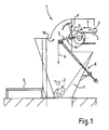
- FIG. 1 shows a schematic side view of a sorting device 1 with a conveyor belt 2 in which objects 3 are conveyed in the conveying direction 4.
- the objects 3 have already been subjected to presorting.
- a loading 5 is provided (in total, several stores are available for all channels, cf. FIG. 2 ).
- the tray 5 can be tilted downwards, wherein the angle ⁇ between the conveying path of the conveyor belt 2 and the tray 5 on the side facing away from the objects is less than 180 ° (180 degrees). From the drawer, the objects can fall over a drop section 6 into a container 7.
- the drawer 5 can be actuated via an actuating lever 8, that is, with this, the tilting of the drawer can be adjusted or the drawer can be completely folded down.
- a Sortiertribüne 9 is arranged, which can be an operator to perform the re-sorting in the area of the tray 5.
- the tray 5 is rotatably mounted about a pivot point A and further has a guide F in the present case is designed as a backdrop, so that the guide lever can be performed on a circular arc section.
- FIG. 2 shows the same sorter from above. Shown is also the conveyor belt 2 in the plan view can be seen that the conveyor belt is separated via the partitions 10 into individual channels 11a, 11b, 11c and 11d.
- Channel 11a can for example be assigned to the recyclables group of dark PET bottles and PET hollow bodies, the channel 11b to transparent PET bottles or hollow bodies, the channel 11c to plastic bodies made of PEHD (hard polyethylene) and the channel 11d to other plastic parts.
- PEHD hard polyethylene
- the store 5a - 5d are slightly folded down in the present case, that is called in the drawing of FIG. 2 viewed from the top view in the direction of the drawing plane. Shown after the store 5a - 5d, the passage openings 12a - 12d.
- Channel 11a currently has a relatively large collection of objects 3a, channel 11b only a very small collection of objects 3b, while again channels 11c and 11d currently have no objects.
- the setting is the loading 5c and 5d temporarily without meaning.
- the tray 5b can be turned upward to form a slightly inclined chute and the passage opening 12b is small. The few objects 3b can therefore accumulate. The operator concentrates on channel 11a during this time, since there the object volume 3a is substantially higher than in the remaining channels 11b-11d.
- FIG. 3 shows a schematic oblique view of the sorting device of the FIGS. 1 and 2 with an operator 14 on the Sortiertribüne 9.
- the sorting device 1 with the conveyor belt 2, the partitions 10 for the separation of the individual channels 11 (or a total of 11a to 11d).
- the operator 14 stands on a sorting platform 9 and sorts the individual objects within the individual channels 11a to 11d in order to obtain a particularly high degree of purity of the sorting waste. From the drawer 5, the sorted objects fall into the containers 7, whereby these can be assigned to the individual channels depending on the recycling groups.
- Side of the operator 14 and the Sortiertribüne 9 are the waste containers 13a and 13b can be disposed of in the contaminants.
- the Sortiertribüne 9 is, as can be seen here, arranged so that the conveyor belt 2 with its conveying direction 4 conveys the objects directly in the direction of the operator. Since this conveyor line ends almost immediately in front of the operator 14, a sorting with the aid of the store 5a-5d is easily possible.
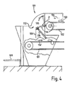
- FIG. 4 shows a similar sorting device 101 with a conveyor belt 102 for sorting objects 103, which are moved on the conveyor belt in the direction of the arrow 104.
- the objects 103 reach one of the stores 105 and fall over a drop section 106 onto another conveyor belt 107, this conveyor belt moves in the opposite direction 104 '(opposite in comparison to the conveying direction 104).
- the drawer 105 may also be connected via an actuating lever 108, which in FIG. 4 indicated only schematically is folded or positioned.
- the sorting turret 109 is also provided.
- the objects can in turn reach the drop distance via a passage opening 112.
- the tray 105 can in turn be stored similarly, wherein the angle ⁇ on the side still facing away from the objects side is less than 180 °, the tray 105 is thus designed as a slide.
- a transport device 107 is provided, with which the re-sorted items can be transported on and then further processed, shredded or sorted again.
- a combination of a device according to the FIGS. 1 and 4 so that the conveyor belt 107 does not extend over the entire width of the individual channels, for example, but only some of the channels finally land on the conveyor belt 107, while others in turn open directly into a container (see container 7).
- the device for sorting and controlled conveyance of objects to be sorted according to material groups can also be referred to as a so-called "front sorting station".
Landscapes
- Sorting Of Articles (AREA)
Claims (15)
- Dispositif (1, 101) pour le tri et le convoyage contrôlé d'objets (3, 103) à trier en groupes de matériaux pour la séparation des matériaux et l'élimination des déchets, qui comprend une tribune de tri (9, 109) pour le tri des objets et au moins un dispositif de transport (2, 102) pour le transport des objets sur un trajet de transport vers la tribune de tri, le dispositif de transport comprenant au moins une cloison (10, 110) avec laquelle le trajet de transport peut être divisé en au moins deux canaux (11 ; 11 a ; 11 b ; 11 c ; 11 d) et un groupe de matériau pouvant être attribué à chaque canal, une portion de chute (6, 106) étant disposée en aval de chaque trajet de transport et, entre le trajet de transport et la portion de chute, au moins une trémie (5, 105 ; 5a, 5b, 5c, 5d) étant disposé comme un obstacle mécanique lors du convoyage des objets du trajet de transport vers la portion de chute.
- Dispositif de tri et de convoyage contrôlé d'objets selon la revendication 1, caractérisé en ce que la portion de chute est limitée par une paroi de limitation sur au moins un côté et en ce que la trémie est disposée de façon à ce que, entre la trémie et la paroi de limitation une ouverture de passage (12, 112) vers la portion de chute puisse être formée.
- Dispositif de tri et de convoyage contrôlé d'objets selon l'une des revendications précédentes, caractérisé en ce que la trémie est conçue comme une glissière qui forme sur le côté supérieur, sur lequel les objets peuvent être convoyés, un angle (β) supérieur à 180 degrés avec le trajet de transport.
- Dispositif de tri et de convoyage contrôlé d'objets selon l'une des revendications précédentes, caractérisé en ce que la trémie est logée de manière rotative et peut être réglée en ce qui concerne son angle (α, β) par rapport au trajet de transport et/ou à la paroi de limitation de la portion de chute.
- Dispositif de tri et de convoyage contrôlé d'objets selon l'une des revendications précédentes, caractérisé en ce que la trémie est conçue de manière mobile, plus particulièrement comme un dispositif de rabattement, pour convoyer, grâce au pivotement du dispositif de rabattement au niveau de la trémie, des objets bloqués sur la portion de chute.
- Dispositif de tri et de convoyage contrôlé d'objets selon l'une des revendications précédentes, caractérisé en ce que la tribune de tri est conçue pour permettre un accès aux canaux.
- Dispositif de tri et de convoyage contrôlé d'objets selon l'une des revendications précédentes, caractérisé en ce que la tribune de tri comprend un dispositif de commande pour le réglage de l'angle et/ou pour le déplacement de la trémie.
- Dispositif de tri et de convoyage contrôlé d'objets selon l'une des revendications précédentes, caractérisé en ce que la portion de chute est divisée par au moins un dispositif de blocage en portions de chute partielles correspondant chacune à une trémie et/ou à un canal.
- Dispositif de tri et de convoyage contrôlé d'objets selon l'une des revendications précédentes, caractérisé en ce qu'un récipient (7) est disposé en aval de la portion de chute et le récipient est monté de façon à ce que les objets puissent tomber dans les récipients correspondants.
- Dispositif de tri et de convoyage contrôlé d'objets selon l'une des revendications précédentes, caractérisé en ce qu'un autre dispositif de transport (107) est disposé en aval de la portion de chute.
- Dispositif de tri et de convoyage contrôlé d'objets selon l'une des revendications précédentes, caractérisé en ce que le dispositif de transport (2, 102) et/ou l'autre dispositif de transport (107) est/sont conçu(s) comme un convoyeur à bande.
- Dispositif de tri et de convoyage contrôlé d'objets selon l'une des revendications précédentes, caractérisé en ce que les canaux sont disposés les uns à côté des autres et/ou en ce qu'exactement une trémie correspond à chaque canal.
- Dispositif de tri et de convoyage contrôlé d'objets selon l'une des revendications précédentes, caractérisé en ce que, directement adjacent à la tribune, se trouve au moins un récipient de collecte (13a, 13b) pour la collecte de matières parasites et/ou d'objets qui ne peuvent être classées dans aucun des groupes de matériaux.
- Dispositif de tri et de convoyage contrôlé d'objets selon l'une des revendications précédentes, caractérisé en ce que chacun des récipients correspond à exactement un canal ou au moins un des récipients comprend des récipients partiels dont chacun correspond à exactement un canal.
- Dispositif de tri et de convoyage contrôlé d'objets selon l'une des revendications précédentes, caractérisé en ce qu'un entonnoir d'éjection, destiné au convoyage de matières parasites et d'objets qui ne peuvent être classées dans aucun des groupes de matériaux, de la trémie vers un des récipients de collecte (13a, 13b).
Applications Claiming Priority (1)
| Application Number | Priority Date | Filing Date | Title |
|---|---|---|---|
| DE201220001478 DE202012001478U1 (de) | 2012-02-15 | 2012-02-15 | Vorrichtung zum Sortieren und kontrollierten Befördern |
Publications (2)
| Publication Number | Publication Date |
|---|---|
| EP2628552A1 EP2628552A1 (fr) | 2013-08-21 |
| EP2628552B1 true EP2628552B1 (fr) | 2015-02-25 |
Family
ID=46579918
Family Applications (1)
| Application Number | Title | Priority Date | Filing Date |
|---|---|---|---|
| EP20120008395 Active EP2628552B1 (fr) | 2012-02-15 | 2012-12-18 | Dispositif de tri et de transport contrôlé |
Country Status (2)
| Country | Link |
|---|---|
| EP (1) | EP2628552B1 (fr) |
| DE (1) | DE202012001478U1 (fr) |
Families Citing this family (1)
| Publication number | Priority date | Publication date | Assignee | Title |
|---|---|---|---|---|
| CN110125051A (zh) * | 2019-04-21 | 2019-08-16 | 湖北协利纺织有限公司 | 一种废棉回收用筛选装置 |
Family Cites Families (3)
| Publication number | Priority date | Publication date | Assignee | Title |
|---|---|---|---|---|
| US5117982A (en) * | 1990-10-09 | 1992-06-02 | Shotthafer Daniel S | Small part sorting tray |
| GB2269774B (en) * | 1992-07-28 | 1995-11-22 | Firbank & Sons Limited C | Can processing plant |
| FR2800304A1 (fr) * | 1999-10-28 | 2001-05-04 | Arbor Sa | Installation de tri selectif de dechets |
-
2012
- 2012-02-15 DE DE201220001478 patent/DE202012001478U1/de not_active Expired - Lifetime
- 2012-12-18 EP EP20120008395 patent/EP2628552B1/fr active Active
Also Published As
| Publication number | Publication date |
|---|---|
| DE202012001478U1 (de) | 2012-06-26 |
| EP2628552A1 (fr) | 2013-08-21 |
Similar Documents
| Publication | Publication Date | Title |
|---|---|---|
| EP3254893B1 (fr) | Véhicule de livraison et procédé de livraison d'envois à différents endroits le long d'un itinéraire | |
| EP2958838B1 (fr) | Dispositif et procédé de transport d'objets | |
| DE69308025T2 (de) | Vorrichtung und verfahren zum trennen von wiederverwertbarem material | |
| EP2791017B1 (fr) | Appareil et procédé pour vider des porte-charges, remplis de marchandises | |
| EP1868923B1 (fr) | Dispositif de transport comprenant au moins une glissiere pour des articles de detail et procede pour empiler des articles de detail dans un conteneur | |
| EP2861403B1 (fr) | Dispositif de séparation de préformes pourvu d'un mécanisme permettant d'éliminer les préformes mal positionnées | |
| EP1970868A1 (fr) | Dispositif et procédé destinés au stockage automatique de marchandises au détail | |
| EP2509901A1 (fr) | Dispositif de triage | |
| DE2114481A1 (de) | Vorrichtung fur die Abgabe abge messener Mengen von teilchenförmigen Waren | |
| EP4021831A1 (fr) | Procédé et système pour trier des articles à trier à position instable | |
| EP3208001B1 (fr) | Séparateur pneumatique doté d'une triple séparation | |
| EP4049949A1 (fr) | Dispositif et procédé pour le chargement d'un récipient comportant des marchandises en vrac triées | |
| DE69700944T2 (de) | Rutsche für Sortiereinrichtung | |
| DE7435092U (de) | Vorrichtung zum sortieren von in mahlwerken verwendeten mahlkoerpern | |
| EP2859802B1 (fr) | Dispositif et procédé de transport et de tri d'articles à fumer | |
| EP0123825B1 (fr) | Installation de triage notamment pour extraire des produits de valeur des déchets ménagers, industriels, encombrants, secs et/ou des matières dangereuses et posant un problème | |
| EP2805780B1 (fr) | Sas d'épierrage doté de dépoussiéreur pneumatique | |
| DE19545240A1 (de) | Verfahren und Vorrichtung zum Trennen von Materialgemischen nach der Sorte | |
| DE102014011401B3 (de) | "Ausblasvorrichtung zum selektiven Ausblasen von Fördergutteilen aus einem Fördergutstrom" | |
| EP2628552A1 (fr) | Dispositif de tri et de transport contrôlé | |
| DE2837037C2 (de) | Drehtrommel-Luftstrom-Sortiervorrichtung zum Trennen von Feststoffgemischen wie Müll und dergleichen | |
| DE9417627U1 (de) | Müllvorsortierer | |
| DE10123304A1 (de) | Vorrichtung und Verfahren zur Sortierung eines Abfallgemisches | |
| DE102010042333A1 (de) | Vorrichtung zum Ausrichten von Gegenständen | |
| DE19732442A1 (de) | Verfahren und Anlage zum Sortieren eines Wertstoffgemisches |
Legal Events
| Date | Code | Title | Description |
|---|---|---|---|
| PUAI | Public reference made under article 153(3) epc to a published international application that has entered the european phase |
Free format text: ORIGINAL CODE: 0009012 |
|
| AK | Designated contracting states |
Kind code of ref document: A1 Designated state(s): AL AT BE BG CH CY CZ DE DK EE ES FI FR GB GR HR HU IE IS IT LI LT LU LV MC MK MT NL NO PL PT RO RS SE SI SK SM TR |
|
| AX | Request for extension of the european patent |
Extension state: BA ME |
|
| 17P | Request for examination filed |
Effective date: 20131202 |
|
| RBV | Designated contracting states (corrected) |
Designated state(s): AL AT BE BG CH CY CZ DE DK EE ES FI FR GB GR HR HU IE IS IT LI LT LU LV MC MK MT NL NO PL PT RO RS SE SI SK SM TR |
|
| GRAP | Despatch of communication of intention to grant a patent |
Free format text: ORIGINAL CODE: EPIDOSNIGR1 |
|
| INTG | Intention to grant announced |
Effective date: 20141113 |
|
| GRAS | Grant fee paid |
Free format text: ORIGINAL CODE: EPIDOSNIGR3 |
|
| GRAA | (expected) grant |
Free format text: ORIGINAL CODE: 0009210 |
|
| AK | Designated contracting states |
Kind code of ref document: B1 Designated state(s): AL AT BE BG CH CY CZ DE DK EE ES FI FR GB GR HR HU IE IS IT LI LT LU LV MC MK MT NL NO PL PT RO RS SE SI SK SM TR |
|
| REG | Reference to a national code |
Ref country code: GB Ref legal event code: FG4D Free format text: NOT ENGLISH |
|
| REG | Reference to a national code |
Ref country code: CH Ref legal event code: EP |
|
| REG | Reference to a national code |
Ref country code: IE Ref legal event code: FG4D Free format text: LANGUAGE OF EP DOCUMENT: GERMAN |
|
| REG | Reference to a national code |
Ref country code: DE Ref legal event code: R096 Ref document number: 502012002311 Country of ref document: DE Effective date: 20150409 |
|
| REG | Reference to a national code |
Ref country code: AT Ref legal event code: REF Ref document number: 711474 Country of ref document: AT Kind code of ref document: T Effective date: 20150415 |
|
| REG | Reference to a national code |
Ref country code: NL Ref legal event code: VDEP Effective date: 20150225 |
|
| REG | Reference to a national code |
Ref country code: LT Ref legal event code: MG4D |
|
| PG25 | Lapsed in a contracting state [announced via postgrant information from national office to epo] |
Ref country code: HR Free format text: LAPSE BECAUSE OF FAILURE TO SUBMIT A TRANSLATION OF THE DESCRIPTION OR TO PAY THE FEE WITHIN THE PRESCRIBED TIME-LIMIT Effective date: 20150225 Ref country code: NO Free format text: LAPSE BECAUSE OF FAILURE TO SUBMIT A TRANSLATION OF THE DESCRIPTION OR TO PAY THE FEE WITHIN THE PRESCRIBED TIME-LIMIT Effective date: 20150525 Ref country code: SE Free format text: LAPSE BECAUSE OF FAILURE TO SUBMIT A TRANSLATION OF THE DESCRIPTION OR TO PAY THE FEE WITHIN THE PRESCRIBED TIME-LIMIT Effective date: 20150225 Ref country code: ES Free format text: LAPSE BECAUSE OF FAILURE TO SUBMIT A TRANSLATION OF THE DESCRIPTION OR TO PAY THE FEE WITHIN THE PRESCRIBED TIME-LIMIT Effective date: 20150225 Ref country code: FI Free format text: LAPSE BECAUSE OF FAILURE TO SUBMIT A TRANSLATION OF THE DESCRIPTION OR TO PAY THE FEE WITHIN THE PRESCRIBED TIME-LIMIT Effective date: 20150225 Ref country code: LT Free format text: LAPSE BECAUSE OF FAILURE TO SUBMIT A TRANSLATION OF THE DESCRIPTION OR TO PAY THE FEE WITHIN THE PRESCRIBED TIME-LIMIT Effective date: 20150225 |
|
| PG25 | Lapsed in a contracting state [announced via postgrant information from national office to epo] |
Ref country code: LV Free format text: LAPSE BECAUSE OF FAILURE TO SUBMIT A TRANSLATION OF THE DESCRIPTION OR TO PAY THE FEE WITHIN THE PRESCRIBED TIME-LIMIT Effective date: 20150225 Ref country code: GR Free format text: LAPSE BECAUSE OF FAILURE TO SUBMIT A TRANSLATION OF THE DESCRIPTION OR TO PAY THE FEE WITHIN THE PRESCRIBED TIME-LIMIT Effective date: 20150526 Ref country code: RS Free format text: LAPSE BECAUSE OF FAILURE TO SUBMIT A TRANSLATION OF THE DESCRIPTION OR TO PAY THE FEE WITHIN THE PRESCRIBED TIME-LIMIT Effective date: 20150225 Ref country code: IS Free format text: LAPSE BECAUSE OF FAILURE TO SUBMIT A TRANSLATION OF THE DESCRIPTION OR TO PAY THE FEE WITHIN THE PRESCRIBED TIME-LIMIT Effective date: 20150625 |
|
| PG25 | Lapsed in a contracting state [announced via postgrant information from national office to epo] |
Ref country code: NL Free format text: LAPSE BECAUSE OF FAILURE TO SUBMIT A TRANSLATION OF THE DESCRIPTION OR TO PAY THE FEE WITHIN THE PRESCRIBED TIME-LIMIT Effective date: 20150225 |
|
| PG25 | Lapsed in a contracting state [announced via postgrant information from national office to epo] |
Ref country code: DK Free format text: LAPSE BECAUSE OF FAILURE TO SUBMIT A TRANSLATION OF THE DESCRIPTION OR TO PAY THE FEE WITHIN THE PRESCRIBED TIME-LIMIT Effective date: 20150225 Ref country code: RO Free format text: LAPSE BECAUSE OF FAILURE TO SUBMIT A TRANSLATION OF THE DESCRIPTION OR TO PAY THE FEE WITHIN THE PRESCRIBED TIME-LIMIT Effective date: 20150225 Ref country code: CZ Free format text: LAPSE BECAUSE OF FAILURE TO SUBMIT A TRANSLATION OF THE DESCRIPTION OR TO PAY THE FEE WITHIN THE PRESCRIBED TIME-LIMIT Effective date: 20150225 Ref country code: EE Free format text: LAPSE BECAUSE OF FAILURE TO SUBMIT A TRANSLATION OF THE DESCRIPTION OR TO PAY THE FEE WITHIN THE PRESCRIBED TIME-LIMIT Effective date: 20150225 Ref country code: SK Free format text: LAPSE BECAUSE OF FAILURE TO SUBMIT A TRANSLATION OF THE DESCRIPTION OR TO PAY THE FEE WITHIN THE PRESCRIBED TIME-LIMIT Effective date: 20150225 |
|
| REG | Reference to a national code |
Ref country code: DE Ref legal event code: R097 Ref document number: 502012002311 Country of ref document: DE |
|
| PG25 | Lapsed in a contracting state [announced via postgrant information from national office to epo] |
Ref country code: PL Free format text: LAPSE BECAUSE OF FAILURE TO SUBMIT A TRANSLATION OF THE DESCRIPTION OR TO PAY THE FEE WITHIN THE PRESCRIBED TIME-LIMIT Effective date: 20150225 |
|
| REG | Reference to a national code |
Ref country code: FR Ref legal event code: PLFP Year of fee payment: 4 |
|
| PG25 | Lapsed in a contracting state [announced via postgrant information from national office to epo] |
Ref country code: IT Free format text: LAPSE BECAUSE OF FAILURE TO SUBMIT A TRANSLATION OF THE DESCRIPTION OR TO PAY THE FEE WITHIN THE PRESCRIBED TIME-LIMIT Effective date: 20150225 |
|
| PLBE | No opposition filed within time limit |
Free format text: ORIGINAL CODE: 0009261 |
|
| STAA | Information on the status of an ep patent application or granted ep patent |
Free format text: STATUS: NO OPPOSITION FILED WITHIN TIME LIMIT |
|
| 26N | No opposition filed |
Effective date: 20151126 |
|
| PG25 | Lapsed in a contracting state [announced via postgrant information from national office to epo] |
Ref country code: SI Free format text: LAPSE BECAUSE OF FAILURE TO SUBMIT A TRANSLATION OF THE DESCRIPTION OR TO PAY THE FEE WITHIN THE PRESCRIBED TIME-LIMIT Effective date: 20150225 |
|
| PG25 | Lapsed in a contracting state [announced via postgrant information from national office to epo] |
Ref country code: BE Free format text: LAPSE BECAUSE OF NON-PAYMENT OF DUE FEES Effective date: 20151231 |
|
| PG25 | Lapsed in a contracting state [announced via postgrant information from national office to epo] |
Ref country code: MC Free format text: LAPSE BECAUSE OF FAILURE TO SUBMIT A TRANSLATION OF THE DESCRIPTION OR TO PAY THE FEE WITHIN THE PRESCRIBED TIME-LIMIT Effective date: 20150225 Ref country code: LU Free format text: LAPSE BECAUSE OF FAILURE TO SUBMIT A TRANSLATION OF THE DESCRIPTION OR TO PAY THE FEE WITHIN THE PRESCRIBED TIME-LIMIT Effective date: 20151218 |
|
| REG | Reference to a national code |
Ref country code: CH Ref legal event code: PL |
|
| REG | Reference to a national code |
Ref country code: IE Ref legal event code: MM4A |
|
| PG25 | Lapsed in a contracting state [announced via postgrant information from national office to epo] |
Ref country code: LI Free format text: LAPSE BECAUSE OF NON-PAYMENT OF DUE FEES Effective date: 20151231 Ref country code: IE Free format text: LAPSE BECAUSE OF NON-PAYMENT OF DUE FEES Effective date: 20151218 Ref country code: CH Free format text: LAPSE BECAUSE OF NON-PAYMENT OF DUE FEES Effective date: 20151231 |
|
| REG | Reference to a national code |
Ref country code: FR Ref legal event code: PLFP Year of fee payment: 5 |
|
| PG25 | Lapsed in a contracting state [announced via postgrant information from national office to epo] |
Ref country code: BG Free format text: LAPSE BECAUSE OF FAILURE TO SUBMIT A TRANSLATION OF THE DESCRIPTION OR TO PAY THE FEE WITHIN THE PRESCRIBED TIME-LIMIT Effective date: 20150225 Ref country code: SM Free format text: LAPSE BECAUSE OF FAILURE TO SUBMIT A TRANSLATION OF THE DESCRIPTION OR TO PAY THE FEE WITHIN THE PRESCRIBED TIME-LIMIT Effective date: 20150225 Ref country code: HU Free format text: LAPSE BECAUSE OF FAILURE TO SUBMIT A TRANSLATION OF THE DESCRIPTION OR TO PAY THE FEE WITHIN THE PRESCRIBED TIME-LIMIT; INVALID AB INITIO Effective date: 20121218 |
|
| PG25 | Lapsed in a contracting state [announced via postgrant information from national office to epo] |
Ref country code: CY Free format text: LAPSE BECAUSE OF FAILURE TO SUBMIT A TRANSLATION OF THE DESCRIPTION OR TO PAY THE FEE WITHIN THE PRESCRIBED TIME-LIMIT Effective date: 20150225 |
|
| GBPC | Gb: european patent ceased through non-payment of renewal fee |
Effective date: 20161218 |
|
| PG25 | Lapsed in a contracting state [announced via postgrant information from national office to epo] |
Ref country code: MT Free format text: LAPSE BECAUSE OF FAILURE TO SUBMIT A TRANSLATION OF THE DESCRIPTION OR TO PAY THE FEE WITHIN THE PRESCRIBED TIME-LIMIT Effective date: 20150225 |
|
| PG25 | Lapsed in a contracting state [announced via postgrant information from national office to epo] |
Ref country code: GB Free format text: LAPSE BECAUSE OF NON-PAYMENT OF DUE FEES Effective date: 20161218 |
|
| REG | Reference to a national code |
Ref country code: FR Ref legal event code: PLFP Year of fee payment: 6 |
|
| PG25 | Lapsed in a contracting state [announced via postgrant information from national office to epo] |
Ref country code: TR Free format text: LAPSE BECAUSE OF FAILURE TO SUBMIT A TRANSLATION OF THE DESCRIPTION OR TO PAY THE FEE WITHIN THE PRESCRIBED TIME-LIMIT Effective date: 20150225 Ref country code: MK Free format text: LAPSE BECAUSE OF FAILURE TO SUBMIT A TRANSLATION OF THE DESCRIPTION OR TO PAY THE FEE WITHIN THE PRESCRIBED TIME-LIMIT Effective date: 20150225 Ref country code: PT Free format text: LAPSE BECAUSE OF FAILURE TO SUBMIT A TRANSLATION OF THE DESCRIPTION OR TO PAY THE FEE WITHIN THE PRESCRIBED TIME-LIMIT Effective date: 20150225 |
|
| PG25 | Lapsed in a contracting state [announced via postgrant information from national office to epo] |
Ref country code: AL Free format text: LAPSE BECAUSE OF FAILURE TO SUBMIT A TRANSLATION OF THE DESCRIPTION OR TO PAY THE FEE WITHIN THE PRESCRIBED TIME-LIMIT Effective date: 20150225 |
|
| REG | Reference to a national code |
Ref country code: AT Ref legal event code: MM01 Ref document number: 711474 Country of ref document: AT Kind code of ref document: T Effective date: 20171218 |
|
| PG25 | Lapsed in a contracting state [announced via postgrant information from national office to epo] |
Ref country code: AT Free format text: LAPSE BECAUSE OF NON-PAYMENT OF DUE FEES Effective date: 20171218 |
|
| REG | Reference to a national code |
Ref country code: DE Ref legal event code: R082 Ref document number: 502012002311 Country of ref document: DE Representative=s name: RAVENSPAT PATENTANWAELTE PARTNERSCHAFT MBB, DE |
|
| PGFP | Annual fee paid to national office [announced via postgrant information from national office to epo] |
Ref country code: FR Payment date: 20251218 Year of fee payment: 14 |
|
| PGFP | Annual fee paid to national office [announced via postgrant information from national office to epo] |
Ref country code: DE Payment date: 20251222 Year of fee payment: 14 |