EP2626236B1 - Motor vehicle with a seating bench - Google Patents
Motor vehicle with a seating bench Download PDFInfo
- Publication number
- EP2626236B1 EP2626236B1 EP12154890.3A EP12154890A EP2626236B1 EP 2626236 B1 EP2626236 B1 EP 2626236B1 EP 12154890 A EP12154890 A EP 12154890A EP 2626236 B1 EP2626236 B1 EP 2626236B1
- Authority
- EP
- European Patent Office
- Prior art keywords
- backrest
- motor vehicle
- partition
- seat surface
- region
- Prior art date
- Legal status (The legal status is an assumption and is not a legal conclusion. Google has not performed a legal analysis and makes no representation as to the accuracy of the status listed.)
- Active
Links
- 238000005192 partition Methods 0.000 claims description 54
- 238000007789 sealing Methods 0.000 claims description 4
- 239000011521 glass Substances 0.000 claims description 2
- 239000012780 transparent material Substances 0.000 claims description 2
- 238000000926 separation method Methods 0.000 description 4
- 238000010586 diagram Methods 0.000 description 2
- 230000007246 mechanism Effects 0.000 description 2
- 230000007704 transition Effects 0.000 description 2
- 230000015572 biosynthetic process Effects 0.000 description 1
- 230000001419 dependent effect Effects 0.000 description 1
- 238000011161 development Methods 0.000 description 1
- 230000018109 developmental process Effects 0.000 description 1
- 230000000694 effects Effects 0.000 description 1
Images

Classifications
-
- B—PERFORMING OPERATIONS; TRANSPORTING
- B60—VEHICLES IN GENERAL
- B60N—SEATS SPECIALLY ADAPTED FOR VEHICLES; VEHICLE PASSENGER ACCOMMODATION NOT OTHERWISE PROVIDED FOR
- B60N2/00—Seats specially adapted for vehicles; Arrangement or mounting of seats in vehicles
- B60N2/24—Seats specially adapted for vehicles; Arrangement or mounting of seats in vehicles for particular purposes or particular vehicles
- B60N2/32—Seats specially adapted for vehicles; Arrangement or mounting of seats in vehicles for particular purposes or particular vehicles convertible for other use
-
- B—PERFORMING OPERATIONS; TRANSPORTING
- B60—VEHICLES IN GENERAL
- B60N—SEATS SPECIALLY ADAPTED FOR VEHICLES; VEHICLE PASSENGER ACCOMMODATION NOT OTHERWISE PROVIDED FOR
- B60N2/00—Seats specially adapted for vehicles; Arrangement or mounting of seats in vehicles
- B60N2/02—Seats specially adapted for vehicles; Arrangement or mounting of seats in vehicles the seat or part thereof being movable, e.g. adjustable
- B60N2/0224—Non-manual adjustments, e.g. with electrical operation
- B60N2/02246—Electric motors therefor
- B60N2/02253—Electric motors therefor characterised by the transmission between the electric motor and the seat or seat parts
-
- B—PERFORMING OPERATIONS; TRANSPORTING
- B60—VEHICLES IN GENERAL
- B60N—SEATS SPECIALLY ADAPTED FOR VEHICLES; VEHICLE PASSENGER ACCOMMODATION NOT OTHERWISE PROVIDED FOR
- B60N2/00—Seats specially adapted for vehicles; Arrangement or mounting of seats in vehicles
- B60N2/02—Seats specially adapted for vehicles; Arrangement or mounting of seats in vehicles the seat or part thereof being movable, e.g. adjustable
- B60N2/22—Seats specially adapted for vehicles; Arrangement or mounting of seats in vehicles the seat or part thereof being movable, e.g. adjustable the back-rest being adjustable
-
- B—PERFORMING OPERATIONS; TRANSPORTING
- B60—VEHICLES IN GENERAL
- B60N—SEATS SPECIALLY ADAPTED FOR VEHICLES; VEHICLE PASSENGER ACCOMMODATION NOT OTHERWISE PROVIDED FOR
- B60N2/00—Seats specially adapted for vehicles; Arrangement or mounting of seats in vehicles
- B60N2/24—Seats specially adapted for vehicles; Arrangement or mounting of seats in vehicles for particular purposes or particular vehicles
- B60N2/30—Non-dismountable or dismountable seats storable in a non-use position, e.g. foldable spare seats
- B60N2/3002—Non-dismountable or dismountable seats storable in a non-use position, e.g. foldable spare seats back-rest movements
- B60N2/3029—Non-dismountable or dismountable seats storable in a non-use position, e.g. foldable spare seats back-rest movements by composed movement
- B60N2/3031—Non-dismountable or dismountable seats storable in a non-use position, e.g. foldable spare seats back-rest movements by composed movement in a longitudinal-vertical plane
-
- B—PERFORMING OPERATIONS; TRANSPORTING
- B60—VEHICLES IN GENERAL
- B60N—SEATS SPECIALLY ADAPTED FOR VEHICLES; VEHICLE PASSENGER ACCOMMODATION NOT OTHERWISE PROVIDED FOR
- B60N2/00—Seats specially adapted for vehicles; Arrangement or mounting of seats in vehicles
- B60N2/24—Seats specially adapted for vehicles; Arrangement or mounting of seats in vehicles for particular purposes or particular vehicles
- B60N2/30—Non-dismountable or dismountable seats storable in a non-use position, e.g. foldable spare seats
- B60N2/3038—Cushion movements
- B60N2/304—Cushion movements by rotation only
- B60N2/3045—Cushion movements by rotation only about transversal axis
- B60N2/305—Cushion movements by rotation only about transversal axis the cushion being hinged on the vehicle frame
-
- B—PERFORMING OPERATIONS; TRANSPORTING
- B60—VEHICLES IN GENERAL
- B60R—VEHICLES, VEHICLE FITTINGS, OR VEHICLE PARTS, NOT OTHERWISE PROVIDED FOR
- B60R21/00—Arrangements or fittings on vehicles for protecting or preventing injuries to occupants or pedestrians in case of accidents or other traffic risks
- B60R21/02—Occupant safety arrangements or fittings, e.g. crash pads
- B60R21/026—Rigid partitions inside vehicles, e.g. between passengers and load compartments
-
- B—PERFORMING OPERATIONS; TRANSPORTING
- B60—VEHICLES IN GENERAL
- B60N—SEATS SPECIALLY ADAPTED FOR VEHICLES; VEHICLE PASSENGER ACCOMMODATION NOT OTHERWISE PROVIDED FOR
- B60N2/00—Seats specially adapted for vehicles; Arrangement or mounting of seats in vehicles
- B60N2/24—Seats specially adapted for vehicles; Arrangement or mounting of seats in vehicles for particular purposes or particular vehicles
- B60N2/32—Seats specially adapted for vehicles; Arrangement or mounting of seats in vehicles for particular purposes or particular vehicles convertible for other use
- B60N2/36—Seats specially adapted for vehicles; Arrangement or mounting of seats in vehicles for particular purposes or particular vehicles convertible for other use into a loading platform
- B60N2002/363—Seats specially adapted for vehicles; Arrangement or mounting of seats in vehicles for particular purposes or particular vehicles convertible for other use into a loading platform characterised by provisions for enhancing the cargo floor surface, e.g. elements closing gaps or enlarging the back-rest surface
Definitions
- the present invention relates to a motor vehicle having a seat which comprises a seat surface which is approximately horizontal in a normal position and a backrest which is approximately vertical in the normal position.
- Such bench seats for motor vehicles are generally known.
- the DE 100 39 789 A1 discloses a motor vehicle with a seat or a seat, the seat cushion of the seat being adjustably mounted between a horizontal position and a vertical position via a pivot axis arranged in the front end section of the seat cushion.
- a partition is provided, which is mounted on or in the seat cushion in a retractable and extendable manner, the partition protruding upward from the seat cushion in a position of use.
- the backrest can be adjusted into a horizontal position in which the back of the backrest connects approximately flush with the floor of the loading space, so that the loading space floor is extended.
- the extendable partition is required.
- JP 2008 105547 A discloses a motor vehicle with a seat according to the preamble of claim 1.
- DE 10 2010 022206 A1 DE 699 589 C.
- FR 2 874 867 A1 further seats movable in partition position disclosed.
- an adjustable seat with a movable loading floor element and out of the US 3 703 310 A. discloses a vehicle with a movable seat in the partition wall and a removable roof element.
- the object is achieved by a motor vehicle with a seat according to claim 1.
- the backrest and the seat are thus adjustable, for example pivotable, that both can be brought into an approximately vertical position.
- the back of the backrest and the underside of the seat are facing backwards in the direction of travel.
- the backrest and the seat are geometrically designed so that the upper edge of the backrest in the partition position reaches the roof of the vehicle on its inside, that is, it is usually connected to a headliner.
- the contact to the headlining can also be made via flat intermediate elements, such as sealing lips.
- the partition consisting of the backrest and seat surface essentially separates the entire height of the interior of the motor vehicle, from the floor to the roof.
- the backrest is pivotally mounted on the seat surface via a first pivot axis in the rear region of the seat surface and the seat surface is pivotably supported on the vehicle frame via a second pivot axis in the front region of the seat surface, and the seat surface and the backrest are in the partition position about the first and second pivot axis swiveling.
- Such an arrangement of swivel axes represents an inexpensive adjustment mechanism for adjusting the backrest and the seat in the above-mentioned vertical positions of the partition position.
- the first swivel axis in the normal position can also be used to adjust the inclination of the backrest so that a comfortable, the individual needs of a vehicle occupant sitting on the bench is made possible.
- the upper backrest edge preferably extends over the entire width of the roof of the motor vehicle and the upper backrest edge is in contact with the roof of the motor vehicle over the entire width in the partition position.
- the upper edge of the backrest therefore essentially covers the entire width of the motor vehicle in the area of the roof lining, as a result of which a better separation is ensured.
- the seat surface and the backrest are preferably designed such that, in the partition position, the partition covers the entire cross section of the motor vehicle.
- the partition which is formed from the backrest and the seat, therefore extends both in height from the floor to the ceiling of the vehicle, and in width from one side of the vehicle to the opposite side, for example from a B-pillar to the opposite B-pillar.
- the seat and the backrest are shaped in such a way that the contour of the partition wall essentially matches the contour of the vehicle interior and thereby covers the entire cross section. This ensures an optimal separation effect of the partition.
- At least one fixing element is advantageously arranged in the interior of the motor vehicle and is designed to fix the backrest and / or the seat surface in the at least approximately vertical position on the motor vehicle in the partition position. This ensures that the partition is held securely in the upright position even while driving.
- the roof of the motor vehicle comprises a removable or displaceable or foldable roof element, which in the partition position of the seat lies behind the partition in the direction of travel.
- a rear part of the roof can thus be removed or moved or folded as a whole or in segments to the front or to the rear, for example as in a known "sliding folding roof”.
- the backrest comprises at least one transparent area which is designed such that the view from the area in the direction of travel in front of the partition wall into the area in the direction of travel behind the partition wall is made possible. This makes it possible to see the rear of the vehicle, for example the loading space, despite the partition being erected.
- the backrest preferably comprises a backrest wall and the backrest wall is formed in the at least one transparent region from transparent material, in particular from glass or plastic.
- the backrest offers the rigidity of a backrest wall, but still allows a view of the area behind the partition.
- the backrest preferably comprises an upholstery.
- the upholstery can preferably be removed, in particular folded away, for example folded away in the direction of travel. This creates a transparent area in the backrest, even if the upholstery is not transparent, as soon as the upholstery is removed or folded away.
- the upholstery in the at least one transparent region is formed by a transparent, air-filled cushion. This allows a view through the partition without removing the upholstery or part of the upholstery.
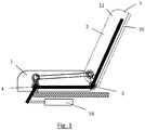
- Fig. 1 is schematically shown a bench according to the invention in a side view.
- the seat bench comprises a seat surface 1 and a backrest 2.
- the backrest 2 can be pivoted relative to the seat surface 1 about the first pivot axis 3 in the rear region of the seat surface 1.
- the seat 1 itself is pivotally mounted on the vehicle frame via the second pivot axis 4.
- the backrest 2 and the seat surface 1 are connected to one another in such a way that actuation via the servomotor 14 causes the backrest 2 and the seat surface 1 to be raised in an approximately vertical position.
- Various folding mechanisms are known for this in the prior art, such as the use of an actuating rod shown or the use of a chain or toothed belt system.
- the backrest 2 is composed of a backrest wall 10 and an upholstery 11.
- the upper backrest edge 5 is located at the upper end of the backrest 2, which lies opposite the first pivot axis 3.
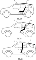
- FIGS. 2a-2c are schematic representations of the seat according to the invention in a motor vehicle, the transition from the normal position in Fig. 2a via an intermediate position as in Fig. 2b shown for the partition position Fig. 2c demonstrate.
- the partition position which in Fig. 2c is shown, the partition from the seat 1 and backrest 2 extends to the roof 6 of the vehicle.
- the partition position which in Fig. 2c is shown, the partition from the seat 1 and backrest 2 extends to the roof 6 of the vehicle.
- the partition element 15 In the direction of travel behind the contact line between the upper edge of the backrest 5 and the roof 6 there is a removable or displaceable (complete or, for example, in segments) roof element 15.
- the entire rear roof area can be removed up to the tailgate of the vehicle, or completely or in segments.
- the partition can also be removed from the partition position using the servomotor 14 Fig. 2c about the intermediate position of the Fig. 2b in the normal position, ie the formation of the usual seat 1
- Fig. 3 is a schematic representation showing a motor vehicle according to the invention with a seat in cross section.
- the seat 1 and the backrest 2 essentially cover the entire cross section of the vehicle.
- the now raised loading floor element 12 which is located at the same height in the partition wall position shown with an already existing loading floor 13.
- Transparent areas 9 are formed in the backrest 2 in that these areas have no upholstery or transparent upholstery and any backrest wall which may be present is made transparent.
- the backrest 2 is fixed on the roof 6 of the vehicle with the aid of fixing elements 8.
- sealing elements 7 are located between the seat surface 1 or the backrest 2 and the frame of the motor vehicle, that is to say the roof, the side walls and possibly — not shown — the loading floor element 12 arranged. This seals the contact surfaces between the partition and the vehicle.
- Fig. 4 finally shows the kinematics of the loading floor lift in a schematic flow diagram.
- the loading floor element 12 is still clearly below the normal loading floor 13, which forms the floor of a loading space behind the seat.
- the loading floor element 12 is raised to the height of the loading floor 13 via the servomotor 14 and the correspondingly mounted linkage on the vehicle, as shown in FIG Fig. 4 shown.
- the invention thus represents a motor vehicle with a seat which enables a separation between a front and a rear area in the motor vehicle in a simple, inexpensive and space-saving manner.
Description
Die vorliegende Erfindung betrifft ein Kraftfahrzeug mit einer Sitzbank, die eine in einer Normalstellung annähernd horizontale Sitzfläche und eine in der Normalstellung annähernd vertikale Lehne umfasst.The present invention relates to a motor vehicle having a seat which comprises a seat surface which is approximately horizontal in a normal position and a backrest which is approximately vertical in the normal position.
Derartige Sitzbänke für Kraftfahrzeuge sind allgemein bekannt.Such bench seats for motor vehicles are generally known.
Die
Weiterhin ist aus der
Es ist eine Aufgabe der Erfindung ein Kraftfahrzeug mit einer Sitzbank anzugeben, das auf einfache, kostengünstige und platzsparende Weise eine Abtrennung zwischen einem vorderen und einem hinteren Bereich im Kraftfahrzeug ermöglicht.It is an object of the invention to provide a motor vehicle with a seat that enables a separation between a front and a rear area in the motor vehicle in a simple, inexpensive and space-saving manner.
Die Lösung der Aufgabe erfolgt durch ein Kraftfahrzeug mit einer Sitzbank nach Anspruch 1.The object is achieved by a motor vehicle with a seat according to
Erfindungsgemäß sind die Lehne und die Sitzfläche also derart verstellbar, beispielsweise schwenkbar, dass beide in eine annähernd vertikale Position gebracht werden können. In der vertikalen Position sind die Rückseite der Lehne und die Unterseite der Sitzfläche in Fahrtrichtung nach hinten ausgerichtet. Die Lehne und die Sitzfläche sind geometrisch so ausgebildet, dass die Oberkante der Lehne in der Trennwandstellung das Dach des Fahrzeuges an dessen Innenseite erreicht, also üblicherweise mit einem Dachhimmel in Verbindung steht. Der Kontakt zum Dachhimmel kann auch über flache Zwischenelemente, wie zum Beispiel Dichtlippen erfolgen. Die Trennwand aus Lehne und Sitzfläche trennt aber im Wesentlichen die gesamte Höhe des Innenraumes des Kraftfahrzeuges, vom Boden bis zum Dach.
Weiterbildungen der Erfindung sind in den abhängigen Ansprüchen, der Beschreibung sowie den beigefügten Zeichnungen angegeben.According to the invention, the backrest and the seat are thus adjustable, for example pivotable, that both can be brought into an approximately vertical position. In the vertical position, the back of the backrest and the underside of the seat are facing backwards in the direction of travel. The backrest and the seat are geometrically designed so that the upper edge of the backrest in the partition position reaches the roof of the vehicle on its inside, that is, it is usually connected to a headliner. The contact to the headlining can also be made via flat intermediate elements, such as sealing lips. However, the partition consisting of the backrest and seat surface essentially separates the entire height of the interior of the motor vehicle, from the floor to the roof.
Further developments of the invention are specified in the dependent claims, the description and the accompanying drawings.
Vorzugsweise ist die Lehne über eine erste Schwenkachse im hinteren Bereich der Sitzfläche an der Sitzfläche schwenkbar gelagert und die Sitzfläche über eine zweite Schwenkachse im vorderen Bereich der Sitzfläche am Fahrzeugrahmen schwenkbar gelagert und die Sitzfläche und die Lehne sind um die erste und zweite Schwenkachse in die Trennwandstellung schwenkbar. Eine derartige Anordnung von Schwenkachsen stellt einen kostengünstigen Verstellmechanismus für die Verstellung der Lehne und der Sitzfläche in die genannten vertikalen Positionen der Trennwandstellung dar. Zudem kann die erste Schwenkachse in der Normalstellung auch dazu genutzt werden, die Neigung der Lehne so einzustellen, dass ein komfortables, den individuellen Bedürfnissen eines Fahrzeuginsassen gerechtes Sitzen auf der Sitzbank ermöglicht wird.
Vorzugsweise erstreckt sich die Lehnenoberkante über die gesamte Breite des Daches des Kraftfahrzeuges und die Lehnenoberkante ist in der Trennwandstellung über die gesamte Breite mit dem Dach des Kraftfahrzeuges in Kontakt. Die Lehnenoberkante deckt daher im Bereich des Dachhimmels im Wesentlichen die gesamte Breite des Kraftfahrzeuges ab wodurch eine bessere Abtrennung gewährleistet ist.Preferably, the backrest is pivotally mounted on the seat surface via a first pivot axis in the rear region of the seat surface and the seat surface is pivotably supported on the vehicle frame via a second pivot axis in the front region of the seat surface, and the seat surface and the backrest are in the partition position about the first and second pivot axis swiveling. Such an arrangement of swivel axes represents an inexpensive adjustment mechanism for adjusting the backrest and the seat in the above-mentioned vertical positions of the partition position. In addition, the first swivel axis in the normal position can also be used to adjust the inclination of the backrest so that a comfortable, the individual needs of a vehicle occupant sitting on the bench is made possible.
The upper backrest edge preferably extends over the entire width of the roof of the motor vehicle and the upper backrest edge is in contact with the roof of the motor vehicle over the entire width in the partition position. The upper edge of the backrest therefore essentially covers the entire width of the motor vehicle in the area of the roof lining, as a result of which a better separation is ensured.
Vorzugsweise sind die Sitzfläche und die Lehne so ausgebildet, dass in der Trennwandstellung die Trennwand den gesamten Querschnitt des Kraftfahrzeuges überdeckt. Die Trennwand, die aus der Lehne und der Sitzfläche gebildet wird, reicht also sowohl in der Höhe vom Boden bis zur Decke des Fahrzeuges, als auch in der Breite von einer Seite des Fahrzeuges bis zur gegenüberliegenden Seite, beispielsweise von einer B-Säule zur gegenüberliegenden B-Säule. Die Sitzfläche und die Lehne sind so geformt, dass die Kontur der Trennwand im Wesentlichen mit der Kontur des Fahrzeug-Innenraumes übereinstimmt und dadurch den gesamten Querschnitt abdeckt. Hierdurch wird eine optimale Trennwirkung der Trennwand sichergestellt.The seat surface and the backrest are preferably designed such that, in the partition position, the partition covers the entire cross section of the motor vehicle. The partition, which is formed from the backrest and the seat, therefore extends both in height from the floor to the ceiling of the vehicle, and in width from one side of the vehicle to the opposite side, for example from a B-pillar to the opposite B-pillar. The seat and the backrest are shaped in such a way that the contour of the partition wall essentially matches the contour of the vehicle interior and thereby covers the entire cross section. This ensures an optimal separation effect of the partition.
Vorteilhaft ist im Innenraum des Kraftfahrzeuges zumindest ein Fixierelement angeordnet, das dazu eingerichtet ist, in der Trennwandstellung die Lehne und/oder die Sitzfläche in der zumindest annähernd vertikalen Position am Kraftfahrzeug zu fixieren. Hierdurch kann ein sicherer Halt der Trennwand in der aufrechten Position auch während der Fahrt sichergestellt werden.At least one fixing element is advantageously arranged in the interior of the motor vehicle and is designed to fix the backrest and / or the seat surface in the at least approximately vertical position on the motor vehicle in the partition position. This ensures that the partition is held securely in the upright position even while driving.
Gemäß einer Ausführungsform der Erfindung umfasst das Dach des Kraftfahrzeuges ein abnehmbares oder verschiebbares oder faltbares Dachelement, das in der Trennwandstellung der Sitzbank in Fahrtrichtung hinter der Trennwand liegt. Ein hinterer Teil des Daches ist also abnehmbar oder als Ganzes oder in Segmenten nach vorne oder nach hinten verschiebbar bzw. faltbar, beispielsweise wie bei einem bekannten "sliding folding roof". Hierdurch entsteht durch Aufrichten von Sitzfläche und Lehne zur Trennwandstellung und Abnehmen bzw. Verschieben oder Falten des hinteren Dachelementes ein Fahrzeug mit hinten offener Ladefläche, entsprechend einem bekannten "Pickup".According to one embodiment of the invention, the roof of the motor vehicle comprises a removable or displaceable or foldable roof element, which in the partition position of the seat lies behind the partition in the direction of travel. A rear part of the roof can thus be removed or moved or folded as a whole or in segments to the front or to the rear, for example as in a known "sliding folding roof". This results in a vehicle with an open loading area at the rear, corresponding to a known "pickup", by raising the seat and backrest to position the partition and removing or moving or folding the rear roof element.
Gemäß einer weiteren Ausführungsform umfasst die Lehne zumindest einen transparenten Bereich, der so ausgebildet ist, dass die Sicht aus dem Bereich in Fahrtrichtung vor der Trennwand in den Bereich in Fahrtrichtung hinter der Trennwand ermöglicht ist. Dadurch ist die Sicht in den hinteren Fahrzeugbereich, also beispielsweise in den Laderaum, trotz aufgerichteter Trennwand möglich.According to a further embodiment, the backrest comprises at least one transparent area which is designed such that the view from the area in the direction of travel in front of the partition wall into the area in the direction of travel behind the partition wall is made possible. This makes it possible to see the rear of the vehicle, for example the loading space, despite the partition being erected.
Bevorzugt umfasst die Lehne eine Lehnenrückwand und die Lehnenrückwand ist in dem zumindest einen transparenten Bereich aus transparentem Material, insbesondere aus Glas oder Kunststoff ausgebildet. Auf diese Weise bietet die Lehne die Steifigkeit einer Lehnenrückwand, erlaubt aber dennoch den Blick in den Bereich hinter der Trennwand.The backrest preferably comprises a backrest wall and the backrest wall is formed in the at least one transparent region from transparent material, in particular from glass or plastic. In this way, the backrest offers the rigidity of a backrest wall, but still allows a view of the area behind the partition.
Bevorzugt umfasst die Lehne eine Polsterung.The backrest preferably comprises an upholstery.
In dem zumindest einen transparenten Bereich ist die Polsterung weiter bevorzugt entfernbar, insbesondere wegklappbar, beispielsweise in Fahrtrichtung nach vorn wegklappbar. Hierdurch entsteht auch bei intransparenter Ausführung der Polsterung ein transparenter Bereich in der Lehne, sobald die Polsterung entfernt bzw. weggeklappt ist.In the at least one transparent area, the upholstery can preferably be removed, in particular folded away, for example folded away in the direction of travel. This creates a transparent area in the backrest, even if the upholstery is not transparent, as soon as the upholstery is removed or folded away.
In einer anderen Ausführungsform ist in dem zumindest einen transparenten Bereich die Polsterung von einem transparenten, luftgefüllten Polster gebildet. Hierdurch ist der Blick durch die Trennwand ohne Entfernen der Polsterung bzw. eines Teiles der Polsterung möglich.In another embodiment, the upholstery in the at least one transparent region is formed by a transparent, air-filled cushion. This allows a view through the partition without removing the upholstery or part of the upholstery.
Die Erfindung wird im Folgenden beispielhaft unter Bezugnahme auf die Zeichnungen beschrieben.
- Fig. 1
- ist eine schematische Darstellung einer erfindungsgemäßen Sitzbank in einer Seitenansicht.
- Fig. 2a - 2c
- sind schematische Darstellungen der Sitzbank gemäß
Fig. 1 , die einen Übergang von der Normalstellung inFig. 2a zur Trennwandstellung inFig. 2c zeigen. - Fig. 3
- ist eine schematische Darstellung die ein erfindungsgemäßes Kraftfahrzeug mit Sitzbank im Querschnitt zeigt.
- Fig. 4
- ist eine schematische Ablaufdarstellung, die die Anhebung eines Ladebodenelementes in 3 Phasen zeigt.
- Fig. 1
- is a schematic representation of a bench according to the invention in a side view.
- 2a-2c
- are schematic representations of the bench in accordance
Fig. 1 making a transition from normal toFig. 2a for partition position inFig. 2c demonstrate. - Fig. 3
- is a schematic representation showing a motor vehicle according to the invention with a seat in cross section.
- Fig. 4
- is a schematic flow diagram showing the lifting of a loading floor element in 3 phases.
In
Die Lehne 2 setzt sich aus einer Lehnenrückwand 10 und einer Polsterung 11 zusammen. Die Lehnenoberkante 5 befindet sich am oberen Ende der Lehne 2, das der ersten Schwenkachse 3 gegenüber liegt.The
Die Erfindung stellt somit ein Kraftfahrzeug mit einer Sitzbank dar, das auf einfache, kostengünstige und platzsparende Weise eine Abtrennung zwischen einem vorderen und einem hinteren Bereich im Kraftfahrzeug ermöglicht.The invention thus represents a motor vehicle with a seat which enables a separation between a front and a rear area in the motor vehicle in a simple, inexpensive and space-saving manner.
- 11
- SitzflächeSeat
- 22nd
- Lehnerest
- 33rd
- erste Schwenkachsefirst pivot axis
- 44th
- zweite Schwenkachsesecond pivot axis
- 55
- LehnenoberkanteTop of backrest
- 66
- Dachtop, roof
- 77
- DichtelementSealing element
- 88th
- FixierelementFixing element
- 99
- transparenter Bereichtransparent area
- 1010th
- LehnenrückwandBackrest wall
- 1111
- Polsterungupholstery
- 1212th
- LadebodenelementLoading floor element
- 1313
- LadebodenLoading floor
- 1414
- StellmotorServomotor
- 1515
- DachelementRoof element
Claims (10)
- Motor vehicle with a seating bench which comprises a seat surface (1) which is approximately horizontal in a normal position and a backrest (2) which is approximately vertical in the normal position, wherein the seat surface (1) and the backrest (2) are adjustable into a partition position in which the seat surface (1) and the backrest (2) adopt an at least approximately vertical position and the backrest (2) is arranged above the seat surface (1), wherein the backrest upper edge (5) is in contact with the roof (6) of the motor vehicle in the partition position, such that the backrest (2) together with the seat surface (1) forms a partition which separates the region behind the partition in the direction of travel from the region in front of the partition in the direction of travel, wherein the partition separates the region behind the partition in the direction of travel from the region in front of the partition in the direction of travel, by means of one or more sealing elements which are arranged between the seat surface (1) and the backrest (2) on the one hand, and the frame of the motor vehicle, i.e. the roof and the side walls, on the other hand, in an approximately soundproof, watertight and/or airtight manner in the partition position, characterized in that a flat loading floor element (12) which, in the normal position of the seating bench, is substantially located under the seat surface (1) is raised in the partition position of the seating bench such that the loading floor element (12) lies in one plane with a loading floor (13) of the motor vehicle in the partition position, wherein the seat surface (1) and the backrest (2) are adjustable into the partition position via a servomotor (14), wherein the loading floor element (12) is raisable via the servomotor (14), at the same time as the seat surface (1) and the backrest (2) are adjustable into the partition position.
- Motor vehicle with a seating bench according to Claim 1,
characterized in that the backrest (2) is mounted pivotably on the seat surface (1) via a first pivot axis (3) in the rear region of the seat surface (1) and the seat surface (1) is mounted pivotably on the vehicle frame via a second pivot axis (4) in the front region of the seat surface (1), and in that the seat surface (1) and the backrest (2) are pivotable about the first and second pivot axes (3, 4) into the partition position. - Motor vehicle with a seating bench according to Claim 1,
characterized in that the backrest upper edge (5) extends over the entire width of the roof (6) of the motor vehicle, and the backrest upper edge (5) is in contact over the entire width with the roof (6) of the motor vehicle in the partition position. - Motor vehicle with a seating bench according to Claim 1,
characterized in that the seat surface (1) and the backrest (2) are designed in such a manner that the partition covers the entire cross section of the motor vehicle in the partition position. - Motor vehicle with a seating bench according to Claim 1,
characterized in that at least one fixing element (8) is arranged in the interior space of the motor vehicle, said fixing element being designed to fix the backrest (2) and/or the seat surface (1) in the at least approximately vertical position to the motor vehicle in the partition position. - Motor vehicle with a seating bench according to Claim 1,
characterized in that the backrest (2) comprises at least one transparent region (9) which is designed in such a manner that the view from the region in front of the partition in the direction of travel into the region behind the partition in the direction of travel is made possible. - Motor vehicle with a seating bench according to Claim 6,
characterized in that the backrest (2) comprises a backrest rear wall (10), and the backrest rear wall (10) is formed from transparent material, in particular from glass or plastic, in the at least one transparent region (9). - Motor vehicle with a seating bench according to Claim 6,
characterized in that the backrest (2) comprises upholstery (11). - Motor vehicle with a seating bench according to Claim 8,
characterized in that the upholstery (11) can be removed, in particular can be folded away, in the at least one transparent region (9). - Motor vehicle with a seating bench according to Claim 8,
characterized in that the upholstery (11) is formed by a transparent, air-filled cushion, in the at least one transparent region (9).
Priority Applications (5)
| Application Number | Priority Date | Filing Date | Title |
|---|---|---|---|
| EP12154890.3A EP2626236B1 (en) | 2012-02-10 | 2012-02-10 | Motor vehicle with a seating bench |
| JP2013020451A JP5696169B2 (en) | 2012-02-10 | 2013-02-05 | Vehicle with seat bench |
| CN201310045453.1A CN103241149B (en) | 2012-02-10 | 2013-02-05 | Motor vehicles with backrest seat |
| KR1020130014372A KR101407102B1 (en) | 2012-02-10 | 2013-02-08 | Motor vehicle with a seat bench |
| US13/763,869 US8985665B2 (en) | 2012-02-10 | 2013-02-11 | Motor vehicle with a seat bench |
Applications Claiming Priority (1)
| Application Number | Priority Date | Filing Date | Title |
|---|---|---|---|
| EP12154890.3A EP2626236B1 (en) | 2012-02-10 | 2012-02-10 | Motor vehicle with a seating bench |
Publications (2)
| Publication Number | Publication Date |
|---|---|
| EP2626236A1 EP2626236A1 (en) | 2013-08-14 |
| EP2626236B1 true EP2626236B1 (en) | 2020-04-01 |
Family
ID=45592214
Family Applications (1)
| Application Number | Title | Priority Date | Filing Date |
|---|---|---|---|
| EP12154890.3A Active EP2626236B1 (en) | 2012-02-10 | 2012-02-10 | Motor vehicle with a seating bench |
Country Status (5)
| Country | Link |
|---|---|
| US (1) | US8985665B2 (en) |
| EP (1) | EP2626236B1 (en) |
| JP (1) | JP5696169B2 (en) |
| KR (1) | KR101407102B1 (en) |
| CN (1) | CN103241149B (en) |
Families Citing this family (8)
| Publication number | Priority date | Publication date | Assignee | Title |
|---|---|---|---|---|
| US8973999B2 (en) * | 2012-03-27 | 2015-03-10 | Ford Global Technologies, Llc | Reclining vehicle seat with actuator and motor |
| JP2015229483A (en) * | 2014-06-07 | 2015-12-21 | トヨタ自動車東日本株式会社 | Vehicular partition and vehicle |
| GB2539500B (en) | 2015-06-19 | 2019-08-21 | Jaguar Land Rover Ltd | Improvements relating to automotive bulkheads |
| GB2555103B (en) * | 2016-10-14 | 2019-05-08 | Ford Global Tech Llc | A motor vehicle having a multi-functional vehicle seat |
| KR102167568B1 (en) | 2020-03-11 | 2020-10-20 | 톈진 나가르 메커니컬 인더스트리 리미티드 컴퍼니 | High-pressure Plunger Type Double Diaphragm Pump |
| KR102167561B1 (en) | 2020-03-11 | 2020-10-20 | 톈진 나가르 메커니컬 인더스트리 리미티드 컴퍼니 | High-pressure Plunger Type Single Diaphragm Pump |
| US11926248B2 (en) | 2022-01-10 | 2024-03-12 | Faurecia Automotive Seating, Llc | Vehicle and occupant support for a vehicle |
| US11820265B2 (en) | 2022-02-03 | 2023-11-21 | Brose Fahrzeugteile SE & Co. Kommanditgesellschaft, Coburg | Vehicle seat |
Family Cites Families (27)
| Publication number | Priority date | Publication date | Assignee | Title |
|---|---|---|---|---|
| DE699589C (en) * | 1937-08-25 | 1940-12-02 | Heinz Doerpmund Dipl Ing | Vehicle box for closed passenger vehicles |
| US3703310A (en) * | 1971-06-01 | 1972-11-21 | Gen Motors Corp | Dual configuration vehicle body |
| JPS61147629A (en) | 1984-12-21 | 1986-07-05 | Toshiba Corp | Pattern detecting circuit |
| JPH0428268Y2 (en) * | 1985-03-06 | 1992-07-08 | ||
| JPH0524606Y2 (en) * | 1988-08-29 | 1993-06-22 | ||
| FR2663270B1 (en) * | 1990-06-13 | 1992-09-18 | Durisotti Sa | SEAT AND PARTICULARLY FOLDABLE BENCH FOR MOTOR VEHICLES. |
| DE4128554A1 (en) * | 1990-09-08 | 1992-03-12 | Volkswagen Ag | Estate car with partition - separates luggage and passenger spaces anpartition can be swung downwards behind seat backrest when not is use |
| JPH0653301U (en) * | 1992-12-31 | 1994-07-19 | 株式会社タチエス | Partition and car seat |
| JPH11342793A (en) * | 1998-06-04 | 1999-12-14 | Honda Motor Co Ltd | Tight-shutting structure of automobile interior |
| JP2000071830A (en) * | 1998-08-28 | 2000-03-07 | Mazda Motor Corp | Body structure for automobile |
| JP2001026241A (en) * | 1999-07-14 | 2001-01-30 | Mazda Motor Corp | Rear body structure for vehicle |
| FR2803565B1 (en) * | 2000-01-06 | 2002-05-24 | Peugeot Citroen Automobiles Sa | VEHICLE CONVERTIBLE IN PICK UP |
| AUPQ597500A0 (en) * | 2000-03-02 | 2000-03-23 | Camatic Pty. Limited | Improved theatre chair |
| DE10039789C2 (en) | 2000-08-16 | 2003-03-06 | Daimler Chrysler Ag | Motor vehicle, in particular passenger cars |
| US6485094B2 (en) * | 2000-12-06 | 2002-11-26 | Asc Incorporated | Automotive vehicle open air system |
| US6305741B1 (en) * | 2001-04-02 | 2001-10-23 | Martin Fernandez | Foldable chair with handle |
| DE60319278T2 (en) * | 2002-03-14 | 2009-02-12 | Intier Automotive Inc., Troy | Foldable, stowable in the ground vehicle seat assembly |
| DE10320527B3 (en) * | 2003-04-30 | 2004-12-09 | Bos Gmbh & Co. Kg | Separating device for a vehicle interior |
| FR2874867A1 (en) * | 2004-09-07 | 2006-03-10 | Renault Sas | Tilting seat arrangement for passenger compartment of motor vehicle, has base tilted around front hinge pillar along vertical position and backrest occupying vertical position, where backrest forms preset angle with base in storing position |
| FR2876637B1 (en) * | 2004-10-14 | 2007-02-02 | Productions Sa Sa B V | REMOVABLE SEPARATION PANEL FOR UTILITY VEHICLE, UTILITY VEHICLE EQUIPPED WITH SUCH A CLOISON |
| JP2008105547A (en) * | 2006-10-25 | 2008-05-08 | Nissan Motor Co Ltd | Cabin rear part structure for automobile |
| JP5191713B2 (en) * | 2007-09-26 | 2013-05-08 | トヨタ紡織株式会社 | Ceiling retractable seat |
| JP2009107372A (en) * | 2007-10-26 | 2009-05-21 | Toyota Boshoku Corp | Ceiling storage type seat |
| US7559667B2 (en) * | 2007-10-26 | 2009-07-14 | Dean Alan Holderman | Lighted cushion |
| FR2923188B1 (en) * | 2007-11-02 | 2010-01-22 | Productions S A B V | SEPARATION DEVICE FOR THE PROTECTION OF PASSENGERS IN A VEHICLE |
| US7762604B1 (en) * | 2009-02-20 | 2010-07-27 | Honda Motor Co., Ltd. | Vehicle seating arrangement |
| DE102010022206A1 (en) * | 2010-05-20 | 2011-11-24 | Brose Fahrzeugteile Gmbh & Co. Kommanditgesellschaft, Coburg | Motor vehicle has interior, back seat, horizontally aligned seat cushion and backrest, where one part of back seat is convertible in cargo guard position |
-
2012
- 2012-02-10 EP EP12154890.3A patent/EP2626236B1/en active Active
-
2013
- 2013-02-05 CN CN201310045453.1A patent/CN103241149B/en active Active
- 2013-02-05 JP JP2013020451A patent/JP5696169B2/en active Active
- 2013-02-08 KR KR1020130014372A patent/KR101407102B1/en active IP Right Grant
- 2013-02-11 US US13/763,869 patent/US8985665B2/en active Active
Non-Patent Citations (1)
| Title |
|---|
| None * |
Also Published As
| Publication number | Publication date |
|---|---|
| US8985665B2 (en) | 2015-03-24 |
| JP5696169B2 (en) | 2015-04-08 |
| JP2013166543A (en) | 2013-08-29 |
| EP2626236A1 (en) | 2013-08-14 |
| KR20130092493A (en) | 2013-08-20 |
| CN103241149B (en) | 2017-09-19 |
| US20130207428A1 (en) | 2013-08-15 |
| KR101407102B1 (en) | 2014-06-13 |
| CN103241149A (en) | 2013-08-14 |
Similar Documents
| Publication | Publication Date | Title |
|---|---|---|
| EP2626236B1 (en) | Motor vehicle with a seating bench | |
| DE10204859A1 (en) | Folding roof with storage space cover | |
| EP0779172B1 (en) | Convertible car with two front seats and rear seating area | |
| EP1634748B1 (en) | Roof system for a vehicle with at least two rigid roof elements | |
| DE202006020522U9 (en) | Vehicle with a device for facilitating entry / exit | |
| DE102017011996B3 (en) | Car with an accessible via a door opening interior | |
| DE10029926C2 (en) | Armrest for a motor vehicle seat | |
| EP2608975A1 (en) | Tilt-and-slide sunroof for a vehicle, comprising a roof opening in which a central beam is arranged | |
| DE102005028802A1 (en) | Cabriolet vehicle with a rear roof part | |
| DE102009035078A1 (en) | Four-wheeled motor vehicle i.e. electric motorization motor vehicle, for urban transportation, has rear seats, where one of seats is movably mounted along axis parallel to longitudinal axis of vehicle between forward and rearward positions | |
| EP1736343B1 (en) | Wind deflector for a convertible vehicle | |
| DE102005037911B3 (en) | Roof system for a motor vehicle comprises a sliding cover which slides behind via rails in the region of the upper sides of triangular side wall sections | |
| DE102014017518A1 (en) | motor vehicle | |
| DE4325306C2 (en) | Wind deflector arrangement for a convertible | |
| EP1215066B1 (en) | Vehicle roof with at least one roof opening and at least one movable panel | |
| DE112016004955B4 (en) | Vehicle rear structure | |
| EP2626237B1 (en) | Motor vehicle with a seating bench | |
| WO2006072272A1 (en) | Motor vehicle having a roof that can be opened | |
| DE10134593A1 (en) | Car sun roof is made up of inflatable, reinforced pockets and slides on curved guide rails, pockets being deflated to allow it to be stored in rear section of roof | |
| DE102006058106A1 (en) | Wind partition e.g. for cabriolet vehicle, has surface element and which is rolled up by roller in storage area and roller is arranged in headrest or integrated in roll-over protection structure | |
| DE102018215733A1 (en) | Seat of a vehicle and vehicle | |
| DE19811884B4 (en) | Passenger cars | |
| DE102012017478B4 (en) | Vehicle roof for a motor vehicle | |
| DE10355056B3 (en) | Seat with movable rear side cover for motor vehicle has cover with toothed region engaging with toothed segment | |
| DE102019211820B4 (en) | Seating arrangement |
Legal Events
| Date | Code | Title | Description |
|---|---|---|---|
| PUAI | Public reference made under article 153(3) epc to a published international application that has entered the european phase |
Free format text: ORIGINAL CODE: 0009012 |
|
| 17P | Request for examination filed |
Effective date: 20121220 |
|
| AK | Designated contracting states |
Kind code of ref document: A1 Designated state(s): AL AT BE BG CH CY CZ DE DK EE ES FI FR GB GR HR HU IE IS IT LI LT LU LV MC MK MT NL NO PL PT RO RS SE SI SK SM TR |
|
| AX | Request for extension of the european patent |
Extension state: BA ME |
|
| RBV | Designated contracting states (corrected) |
Designated state(s): AL AT BE BG CH CY CZ DE DK EE ES FI FR GB GR HR HU IE IS IT LI LT LU LV MC MK MT NL NO PL PT RO RS SE SI SK SM TR |
|
| STAA | Information on the status of an ep patent application or granted ep patent |
Free format text: STATUS: EXAMINATION IS IN PROGRESS |
|
| 17Q | First examination report despatched |
Effective date: 20171205 |
|
| GRAP | Despatch of communication of intention to grant a patent |
Free format text: ORIGINAL CODE: EPIDOSNIGR1 |
|
| STAA | Information on the status of an ep patent application or granted ep patent |
Free format text: STATUS: GRANT OF PATENT IS INTENDED |
|
| INTG | Intention to grant announced |
Effective date: 20200120 |
|
| GRAS | Grant fee paid |
Free format text: ORIGINAL CODE: EPIDOSNIGR3 |
|
| GRAA | (expected) grant |
Free format text: ORIGINAL CODE: 0009210 |
|
| STAA | Information on the status of an ep patent application or granted ep patent |
Free format text: STATUS: THE PATENT HAS BEEN GRANTED |
|
| AK | Designated contracting states |
Kind code of ref document: B1 Designated state(s): AL AT BE BG CH CY CZ DE DK EE ES FI FR GB GR HR HU IE IS IT LI LT LU LV MC MK MT NL NO PL PT RO RS SE SI SK SM TR |
|
| REG | Reference to a national code |
Ref country code: GB Ref legal event code: FG4D Free format text: NOT ENGLISH |
|
| REG | Reference to a national code |
Ref country code: AT Ref legal event code: REF Ref document number: 1250937 Country of ref document: AT Kind code of ref document: T Effective date: 20200415 Ref country code: CH Ref legal event code: EP |
|
| REG | Reference to a national code |
Ref country code: DE Ref legal event code: R096 Ref document number: 502012015908 Country of ref document: DE |
|
| REG | Reference to a national code |
Ref country code: IE Ref legal event code: FG4D Free format text: LANGUAGE OF EP DOCUMENT: GERMAN |
|
| PG25 | Lapsed in a contracting state [announced via postgrant information from national office to epo] |
Ref country code: BG Free format text: LAPSE BECAUSE OF FAILURE TO SUBMIT A TRANSLATION OF THE DESCRIPTION OR TO PAY THE FEE WITHIN THE PRESCRIBED TIME-LIMIT Effective date: 20200701 |
|
| REG | Reference to a national code |
Ref country code: NL Ref legal event code: MP Effective date: 20200401 |
|
| REG | Reference to a national code |
Ref country code: LT Ref legal event code: MG4D |
|
| PG25 | Lapsed in a contracting state [announced via postgrant information from national office to epo] |
Ref country code: PT Free format text: LAPSE BECAUSE OF FAILURE TO SUBMIT A TRANSLATION OF THE DESCRIPTION OR TO PAY THE FEE WITHIN THE PRESCRIBED TIME-LIMIT Effective date: 20200817 Ref country code: LT Free format text: LAPSE BECAUSE OF FAILURE TO SUBMIT A TRANSLATION OF THE DESCRIPTION OR TO PAY THE FEE WITHIN THE PRESCRIBED TIME-LIMIT Effective date: 20200401 Ref country code: NO Free format text: LAPSE BECAUSE OF FAILURE TO SUBMIT A TRANSLATION OF THE DESCRIPTION OR TO PAY THE FEE WITHIN THE PRESCRIBED TIME-LIMIT Effective date: 20200701 Ref country code: FI Free format text: LAPSE BECAUSE OF FAILURE TO SUBMIT A TRANSLATION OF THE DESCRIPTION OR TO PAY THE FEE WITHIN THE PRESCRIBED TIME-LIMIT Effective date: 20200401 Ref country code: GR Free format text: LAPSE BECAUSE OF FAILURE TO SUBMIT A TRANSLATION OF THE DESCRIPTION OR TO PAY THE FEE WITHIN THE PRESCRIBED TIME-LIMIT Effective date: 20200702 Ref country code: SE Free format text: LAPSE BECAUSE OF FAILURE TO SUBMIT A TRANSLATION OF THE DESCRIPTION OR TO PAY THE FEE WITHIN THE PRESCRIBED TIME-LIMIT Effective date: 20200401 Ref country code: IS Free format text: LAPSE BECAUSE OF FAILURE TO SUBMIT A TRANSLATION OF THE DESCRIPTION OR TO PAY THE FEE WITHIN THE PRESCRIBED TIME-LIMIT Effective date: 20200801 Ref country code: NL Free format text: LAPSE BECAUSE OF FAILURE TO SUBMIT A TRANSLATION OF THE DESCRIPTION OR TO PAY THE FEE WITHIN THE PRESCRIBED TIME-LIMIT Effective date: 20200401 Ref country code: CZ Free format text: LAPSE BECAUSE OF FAILURE TO SUBMIT A TRANSLATION OF THE DESCRIPTION OR TO PAY THE FEE WITHIN THE PRESCRIBED TIME-LIMIT Effective date: 20200401 |
|
| PG25 | Lapsed in a contracting state [announced via postgrant information from national office to epo] |
Ref country code: RS Free format text: LAPSE BECAUSE OF FAILURE TO SUBMIT A TRANSLATION OF THE DESCRIPTION OR TO PAY THE FEE WITHIN THE PRESCRIBED TIME-LIMIT Effective date: 20200401 Ref country code: HR Free format text: LAPSE BECAUSE OF FAILURE TO SUBMIT A TRANSLATION OF THE DESCRIPTION OR TO PAY THE FEE WITHIN THE PRESCRIBED TIME-LIMIT Effective date: 20200401 Ref country code: LV Free format text: LAPSE BECAUSE OF FAILURE TO SUBMIT A TRANSLATION OF THE DESCRIPTION OR TO PAY THE FEE WITHIN THE PRESCRIBED TIME-LIMIT Effective date: 20200401 |
|
| PG25 | Lapsed in a contracting state [announced via postgrant information from national office to epo] |
Ref country code: AL Free format text: LAPSE BECAUSE OF FAILURE TO SUBMIT A TRANSLATION OF THE DESCRIPTION OR TO PAY THE FEE WITHIN THE PRESCRIBED TIME-LIMIT Effective date: 20200401 |
|
| REG | Reference to a national code |
Ref country code: DE Ref legal event code: R097 Ref document number: 502012015908 Country of ref document: DE |
|
| PG25 | Lapsed in a contracting state [announced via postgrant information from national office to epo] |
Ref country code: SM Free format text: LAPSE BECAUSE OF FAILURE TO SUBMIT A TRANSLATION OF THE DESCRIPTION OR TO PAY THE FEE WITHIN THE PRESCRIBED TIME-LIMIT Effective date: 20200401 Ref country code: EE Free format text: LAPSE BECAUSE OF FAILURE TO SUBMIT A TRANSLATION OF THE DESCRIPTION OR TO PAY THE FEE WITHIN THE PRESCRIBED TIME-LIMIT Effective date: 20200401 Ref country code: RO Free format text: LAPSE BECAUSE OF FAILURE TO SUBMIT A TRANSLATION OF THE DESCRIPTION OR TO PAY THE FEE WITHIN THE PRESCRIBED TIME-LIMIT Effective date: 20200401 Ref country code: IT Free format text: LAPSE BECAUSE OF FAILURE TO SUBMIT A TRANSLATION OF THE DESCRIPTION OR TO PAY THE FEE WITHIN THE PRESCRIBED TIME-LIMIT Effective date: 20200401 Ref country code: DK Free format text: LAPSE BECAUSE OF FAILURE TO SUBMIT A TRANSLATION OF THE DESCRIPTION OR TO PAY THE FEE WITHIN THE PRESCRIBED TIME-LIMIT Effective date: 20200401 Ref country code: ES Free format text: LAPSE BECAUSE OF FAILURE TO SUBMIT A TRANSLATION OF THE DESCRIPTION OR TO PAY THE FEE WITHIN THE PRESCRIBED TIME-LIMIT Effective date: 20200401 |
|
| PLBE | No opposition filed within time limit |
Free format text: ORIGINAL CODE: 0009261 |
|
| STAA | Information on the status of an ep patent application or granted ep patent |
Free format text: STATUS: NO OPPOSITION FILED WITHIN TIME LIMIT |
|
| PG25 | Lapsed in a contracting state [announced via postgrant information from national office to epo] |
Ref country code: SK Free format text: LAPSE BECAUSE OF FAILURE TO SUBMIT A TRANSLATION OF THE DESCRIPTION OR TO PAY THE FEE WITHIN THE PRESCRIBED TIME-LIMIT Effective date: 20200401 Ref country code: PL Free format text: LAPSE BECAUSE OF FAILURE TO SUBMIT A TRANSLATION OF THE DESCRIPTION OR TO PAY THE FEE WITHIN THE PRESCRIBED TIME-LIMIT Effective date: 20200401 |
|
| 26N | No opposition filed |
Effective date: 20210112 |
|
| PG25 | Lapsed in a contracting state [announced via postgrant information from national office to epo] |
Ref country code: SI Free format text: LAPSE BECAUSE OF FAILURE TO SUBMIT A TRANSLATION OF THE DESCRIPTION OR TO PAY THE FEE WITHIN THE PRESCRIBED TIME-LIMIT Effective date: 20200401 |
|
| PG25 | Lapsed in a contracting state [announced via postgrant information from national office to epo] |
Ref country code: MC Free format text: LAPSE BECAUSE OF FAILURE TO SUBMIT A TRANSLATION OF THE DESCRIPTION OR TO PAY THE FEE WITHIN THE PRESCRIBED TIME-LIMIT Effective date: 20200401 |
|
| GBPC | Gb: european patent ceased through non-payment of renewal fee |
Effective date: 20210210 |
|
| REG | Reference to a national code |
Ref country code: BE Ref legal event code: MM Effective date: 20210228 |
|
| PG25 | Lapsed in a contracting state [announced via postgrant information from national office to epo] |
Ref country code: LI Free format text: LAPSE BECAUSE OF NON-PAYMENT OF DUE FEES Effective date: 20210228 Ref country code: LU Free format text: LAPSE BECAUSE OF NON-PAYMENT OF DUE FEES Effective date: 20210210 Ref country code: CH Free format text: LAPSE BECAUSE OF NON-PAYMENT OF DUE FEES Effective date: 20210228 |
|
| PG25 | Lapsed in a contracting state [announced via postgrant information from national office to epo] |
Ref country code: GB Free format text: LAPSE BECAUSE OF NON-PAYMENT OF DUE FEES Effective date: 20210210 Ref country code: FR Free format text: LAPSE BECAUSE OF NON-PAYMENT OF DUE FEES Effective date: 20210228 Ref country code: IE Free format text: LAPSE BECAUSE OF NON-PAYMENT OF DUE FEES Effective date: 20210210 |
|
| REG | Reference to a national code |
Ref country code: AT Ref legal event code: MM01 Ref document number: 1250937 Country of ref document: AT Kind code of ref document: T Effective date: 20210210 |
|
| PG25 | Lapsed in a contracting state [announced via postgrant information from national office to epo] |
Ref country code: AT Free format text: LAPSE BECAUSE OF NON-PAYMENT OF DUE FEES Effective date: 20210210 |
|
| PG25 | Lapsed in a contracting state [announced via postgrant information from national office to epo] |
Ref country code: BE Free format text: LAPSE BECAUSE OF NON-PAYMENT OF DUE FEES Effective date: 20210228 |
|
| REG | Reference to a national code |
Ref country code: DE Ref legal event code: R081 Ref document number: 502012015908 Country of ref document: DE Owner name: MAGNA STEYR FAHRZEUGTECHNIK GMBH & CO KG, AT Free format text: FORMER OWNER: MAGNA STEYR FAHRZEUGTECHNIK AG & CO. KG, GRAZ, AT |
|
| PG25 | Lapsed in a contracting state [announced via postgrant information from national office to epo] |
Ref country code: HU Free format text: LAPSE BECAUSE OF FAILURE TO SUBMIT A TRANSLATION OF THE DESCRIPTION OR TO PAY THE FEE WITHIN THE PRESCRIBED TIME-LIMIT; INVALID AB INITIO Effective date: 20120210 Ref country code: CY Free format text: LAPSE BECAUSE OF FAILURE TO SUBMIT A TRANSLATION OF THE DESCRIPTION OR TO PAY THE FEE WITHIN THE PRESCRIBED TIME-LIMIT Effective date: 20200401 |
|
| PGFP | Annual fee paid to national office [announced via postgrant information from national office to epo] |
Ref country code: DE Payment date: 20230216 Year of fee payment: 12 |