EP2622800B2 - Système pour optimiser le délai de la transmission de paquet de données de bout en bout dans des réseaux sans fil - Google Patents
Système pour optimiser le délai de la transmission de paquet de données de bout en bout dans des réseaux sans fil Download PDFInfo
- Publication number
- EP2622800B2 EP2622800B2 EP11764326.2A EP11764326A EP2622800B2 EP 2622800 B2 EP2622800 B2 EP 2622800B2 EP 11764326 A EP11764326 A EP 11764326A EP 2622800 B2 EP2622800 B2 EP 2622800B2
- Authority
- EP
- European Patent Office
- Prior art keywords
- data packet
- node
- nodes
- distance
- time
- Prior art date
- Legal status (The legal status is an assumption and is not a legal conclusion. Google has not performed a legal analysis and makes no representation as to the accuracy of the status listed.)
- Active
Links
- 230000005540 biological transmission Effects 0.000 title claims description 108
- 238000005457 optimization Methods 0.000 title 1
- 238000004891 communication Methods 0.000 claims description 34
- 235000008694 Humulus lupulus Nutrition 0.000 description 17
- 238000000034 method Methods 0.000 description 16
- 230000006870 function Effects 0.000 description 12
- 238000012545 processing Methods 0.000 description 11
- 230000001934 delay Effects 0.000 description 9
- 230000003247 decreasing effect Effects 0.000 description 8
- 230000001186 cumulative effect Effects 0.000 description 6
- 230000004044 response Effects 0.000 description 5
- 238000005286 illumination Methods 0.000 description 4
- 206010039203 Road traffic accident Diseases 0.000 description 3
- 230000007423 decrease Effects 0.000 description 3
- 238000010586 diagram Methods 0.000 description 3
- 238000000265 homogenisation Methods 0.000 description 3
- 238000005516 engineering process Methods 0.000 description 2
- 230000002349 favourable effect Effects 0.000 description 2
- 230000006399 behavior Effects 0.000 description 1
- 230000009286 beneficial effect Effects 0.000 description 1
- 230000008901 benefit Effects 0.000 description 1
- 230000001143 conditioned effect Effects 0.000 description 1
- 230000001955 cumulated effect Effects 0.000 description 1
- 230000007613 environmental effect Effects 0.000 description 1
- 238000009434 installation Methods 0.000 description 1
- 230000003993 interaction Effects 0.000 description 1
- 238000007726 management method Methods 0.000 description 1
- 230000007246 mechanism Effects 0.000 description 1
- 238000010295 mobile communication Methods 0.000 description 1
- 238000012544 monitoring process Methods 0.000 description 1
- 230000008569 process Effects 0.000 description 1
- 230000009467 reduction Effects 0.000 description 1
- 230000002441 reversible effect Effects 0.000 description 1
- 230000011218 segmentation Effects 0.000 description 1
- 230000004083 survival effect Effects 0.000 description 1
- 230000002459 sustained effect Effects 0.000 description 1
- 230000001360 synchronised effect Effects 0.000 description 1
- 238000012546 transfer Methods 0.000 description 1
Images


Classifications
-
- H—ELECTRICITY
- H04—ELECTRIC COMMUNICATION TECHNIQUE
- H04W—WIRELESS COMMUNICATION NETWORKS
- H04W28/00—Network traffic management; Network resource management
- H04W28/02—Traffic management, e.g. flow control or congestion control
- H04W28/021—Traffic management, e.g. flow control or congestion control in wireless networks with changing topologies, e.g. ad-hoc networks
-
- H—ELECTRICITY
- H04—ELECTRIC COMMUNICATION TECHNIQUE
- H04W—WIRELESS COMMUNICATION NETWORKS
- H04W40/00—Communication routing or communication path finding
- H04W40/02—Communication route or path selection, e.g. power-based or shortest path routing
- H04W40/20—Communication route or path selection, e.g. power-based or shortest path routing based on geographic position or location
-
- H—ELECTRICITY
- H04—ELECTRIC COMMUNICATION TECHNIQUE
- H04L—TRANSMISSION OF DIGITAL INFORMATION, e.g. TELEGRAPHIC COMMUNICATION
- H04L1/00—Arrangements for detecting or preventing errors in the information received
- H04L1/12—Arrangements for detecting or preventing errors in the information received by using return channel
- H04L1/16—Arrangements for detecting or preventing errors in the information received by using return channel in which the return channel carries supervisory signals, e.g. repetition request signals
- H04L1/18—Automatic repetition systems, e.g. Van Duuren systems
- H04L1/1867—Arrangements specially adapted for the transmitter end
- H04L1/188—Time-out mechanisms
-
- H—ELECTRICITY
- H04—ELECTRIC COMMUNICATION TECHNIQUE
- H04L—TRANSMISSION OF DIGITAL INFORMATION, e.g. TELEGRAPHIC COMMUNICATION
- H04L1/00—Arrangements for detecting or preventing errors in the information received
- H04L1/12—Arrangements for detecting or preventing errors in the information received by using return channel
- H04L1/16—Arrangements for detecting or preventing errors in the information received by using return channel in which the return channel carries supervisory signals, e.g. repetition request signals
- H04L1/18—Automatic repetition systems, e.g. Van Duuren systems
- H04L1/1867—Arrangements specially adapted for the transmitter end
- H04L1/1887—Scheduling and prioritising arrangements
-
- H—ELECTRICITY
- H04—ELECTRIC COMMUNICATION TECHNIQUE
- H04L—TRANSMISSION OF DIGITAL INFORMATION, e.g. TELEGRAPHIC COMMUNICATION
- H04L47/00—Traffic control in data switching networks
- H04L47/10—Flow control; Congestion control
-
- H—ELECTRICITY
- H04—ELECTRIC COMMUNICATION TECHNIQUE
- H04L—TRANSMISSION OF DIGITAL INFORMATION, e.g. TELEGRAPHIC COMMUNICATION
- H04L47/00—Traffic control in data switching networks
- H04L47/10—Flow control; Congestion control
- H04L47/28—Flow control; Congestion control in relation to timing considerations
-
- H—ELECTRICITY
- H04—ELECTRIC COMMUNICATION TECHNIQUE
- H04L—TRANSMISSION OF DIGITAL INFORMATION, e.g. TELEGRAPHIC COMMUNICATION
- H04L67/00—Network arrangements or protocols for supporting network services or applications
- H04L67/01—Protocols
- H04L67/04—Protocols specially adapted for terminals or networks with limited capabilities; specially adapted for terminal portability
-
- H—ELECTRICITY
- H04—ELECTRIC COMMUNICATION TECHNIQUE
- H04L—TRANSMISSION OF DIGITAL INFORMATION, e.g. TELEGRAPHIC COMMUNICATION
- H04L67/00—Network arrangements or protocols for supporting network services or applications
- H04L67/01—Protocols
- H04L67/12—Protocols specially adapted for proprietary or special-purpose networking environments, e.g. medical networks, sensor networks, networks in vehicles or remote metering networks
- H04L67/125—Protocols specially adapted for proprietary or special-purpose networking environments, e.g. medical networks, sensor networks, networks in vehicles or remote metering networks involving control of end-device applications over a network
-
- H—ELECTRICITY
- H04—ELECTRIC COMMUNICATION TECHNIQUE
- H04W—WIRELESS COMMUNICATION NETWORKS
- H04W28/00—Network traffic management; Network resource management
- H04W28/02—Traffic management, e.g. flow control or congestion control
- H04W28/0226—Traffic management, e.g. flow control or congestion control based on location or mobility
-
- H—ELECTRICITY
- H04—ELECTRIC COMMUNICATION TECHNIQUE
- H04W—WIRELESS COMMUNICATION NETWORKS
- H04W8/00—Network data management
- H04W8/02—Processing of mobility data, e.g. registration information at HLR [Home Location Register] or VLR [Visitor Location Register]; Transfer of mobility data, e.g. between HLR, VLR or external networks
- H04W8/04—Registration at HLR or HSS [Home Subscriber Server]
-
- H—ELECTRICITY
- H04—ELECTRIC COMMUNICATION TECHNIQUE
- H04L—TRANSMISSION OF DIGITAL INFORMATION, e.g. TELEGRAPHIC COMMUNICATION
- H04L1/00—Arrangements for detecting or preventing errors in the information received
- H04L2001/0092—Error control systems characterised by the topology of the transmission link
- H04L2001/0097—Relays
Definitions
- the invention relates to a device, a system and a method for controlling data packet transmissions in a wireless network.
- wireless mesh networks attract more and more attention, e.g. for remote control of illumination systems, building automation, monitoring applications, sensor systems and medical applications.
- a remote management of outdoor luminaires so-called telemanagement
- this is driven by environmental concerns, since remote control systems or so-called telemanagement systems enable the use of different dimming patterns, for instance as a function of time, weather conditions and season, allowing a more energy-efficient use of the outdoor lighting system.
- this is also driven by economical reasons, since the increased energy efficiency also reduces operational costs.
- the system can remotely monitor power usage and detect lamp failures, which allows for determining the best time for repairing luminaires or replacing lamps.
- RF radio-frequency
- a data collector In a star network, a data collector has a direct communication path to every node in the network. However, this typically requires a high-power/high-sensitivity base-station-like controller placed at a high location (e.g. on top of a building), which makes the solution cumbersome to deploy and expensive.
- a mesh network the plurality of nodes does in general not communicate directly with the controller, but via so-called multi-hop communications. In a multi-hop communication, a data packet is transmitted from a sender node to a destination node via one or more intermediate nodes.
- Nodes act as routers to transmit data packets from neighboring nodes to nodes that are too far away to reach in a single hop, resulting in a network that can span larger distances. By breaking long distances in a series of shorter hops, signal strength is sustained. Consequently, routing is performed by all nodes of a mesh network, deciding to which neighboring node the data packet is to be sent. Hence, a mesh network is a very robust and stable network with high connectivity and thus high redundancy and reliability.
- mesh network transmission techniques can be divided in two groups: flooding-based and routing-based mesh networks.
- a flooding-based mesh network all data packets are forwarded by all nodes in the network. Therefore, a node does not have to make complicated routing decisions, but just broadcasts the data packet.
- the technique is quite robust.
- Routing-based mesh networks can be further divided into proactive and reactive schemes.
- proactive routing-based mesh networks all needed network paths are stored in routing tables in each node. The routing tables are kept up to date, e.g.
- the number of hops a data packet has to travel is large as compared to a hop distance in small networks.
- 20-40 hops are likely to occur.
- the delivery chance of an individual data packet decreases with its hop distance, since with every hop, there is a chance that the data packet gets lost.
- a big disadvantage in common wireless mesh networks is constituted by the very limited network scalability. This is due to the fact that every data packet or message is transmitted multiple times due to the forwarding, whereby the overall network throughput is reduced. Also, data packet collisions are more likely to occur causing data packet losses, further reducing the overall performance.
- improving the success and reliability of multi-hop end-to-end transmissions is particularly crucial in large-scale multi-hop networks, such as street illumination systems with a high number of luminaire nodes, since end-to-end retransmissions are far more resource/bandwidth costly and delay intensive than in typical smaller networks.
- acknowledgement mode In order to determine whether a data packet is successfully delivered or got lost, data packet transmissions are commonly performed in acknowledgement mode.
- a hop-by-hop acknowledgement mode every hop of the multi-hop transmission is confirmed by the receiving node to the preceding transmitting node.
- this leads to high network load.
- end-to-end acknowledgements are used, wherein the final destination node confirms the receipt of the data packet to the initial sender node.
- the sender node waits for a predetermined time, so-called acknowledgement time-out, before retransmitting the data packet for which it was expecting the acknowledgement.
- the acknowledgement time-out is fixed and common to all nodes of the network.
- WO 2009071692 A1 describes a method for characterizing a communication link by considering transmission characteristics of both a MAC layer and a network layer.
- EP 1 300 990 B1 describes a method involving transmitting data from a first station via at least a second station to at least one further station. At the interfaces between the stations various data processing requirements are used. The data processing requirements are determined depending on a geographic distance to a defined origin, in particular to a first transmission point. Data processing requirements become less stringent with increasing distance.
- KR 2009 0056070 A discloses a method of selecting a relay node by using a competition window in a vehicle ad-hoc network.
- a source node calculates a competition window including all nodes within transmission range.
- Each node within the competition window has a message transmission waiting time that is inverse proportional to its distance from the source node.
- a node whose message transmission waiting time is expired first is selected as a relay node.
- US 6,721,537 B1 describes a method for broadcasting a message in an incomplete radio communication network having a fluctuating number of subscribers for forwarding the message.
- Each subscriber has a transmitting and receiving device for messages and a positioning system for determining its global position. After receiving the message the subscribers determine their own position and the distance from the sender of the message, who is also a subscriber, and transmit the message, with their own position, to further subscribers after a predetermined waiting period, which decreases monotonically as the distance increases.
- EP 1 940 089 A1 describes a data transmission method for controlling an arrival delay.
- a node calculates a cumulative delay of a received packet by using an arrival delay of the packet and a cumulative delay cumulated up to the previous hop. The node then compares the cumulative delay with a target cumulative delay, thereby controlling a transmission profile for the packet so that an expected cumulative delay at the next node becomes closer to a target value. The node writes the cumulative delay in a header of the packet and transmits the packet to the next node using the set transmission profile.
- EP 1 764 964 A2 describes a technology that uses a visibility function within a network environment, in particular a vehicular ad-hoc network including a set of nodes. At least one of the nodes can directly transmit to one or more of a subset of the set of nodes.
- the visibility function characterizes a non-uniform resolution profile within the network environment that extends over at least one node outside the subset of nodes.
- the sent situation information is conditioned to propagate through the network environment according to the visibility function.
- the node can also receive situation information that includes a visibility parameter. Once the situation information is received, the node can evaluate the visibility parameter to determine whether the situation information is eligible for continued propagation through the network environment. If the situation information is eligible for continued propagation the node then transmits the situation information.
- KR 100 832 519 B1 describes a lighting control system using a wireless tag provided to control a lighting group according to a user position by sensing a lighting control signal of the wireless tag through a second wireless switch and transmitting the signal from the second wireless switch to a first wireless switch through an ad-hoc network.
- WO 00/79721 A2 discloses a system for adjusting a time-out for message retransmission, wherein a round-trip communications delay between two devices that communicate with one another over a communications network is repeatedly measured. More specifically, the retransmission time-out is adjusted based upon at least one of the round-trip communications delays that are repeatedly measured. A message that is not acknowledged during the adjustable retransmission time-out is retransmitted.
- the present invention is based on the idea to adjust a probability that a data packet has to be retransmitted based on a distance the data packet has already traveled. By these means, it is possible to minimize the probability that a data packet having already traveled for a large number of hops has to be retransmitted, which would further increase its high delay. Thereby, the total communication delay for long routes can be decreased.
- a device for a node of a wireless network for controlling a data packet transmission, when the node operates as an intermediate node in a multi-hop data packet transmission.
- the control unit of the device can adjust transmission parameters for forwarding a received data packet based on a distance that the data packet has already traveled from a sender node. This increases the probability for a long-traveled data packet to survive the final hops before arriving at its destination node.
- the transmission parameters include at least one of a maximum number of retransmissions at a lower protocol layer, a maximum number of medium access attempts, a transmit power level, a delay time for retransmission and a back-off time for medium access attempts.
- medium access attempt relates to the process of carrier sensing and the subsequent transmitting or retransmitting of a data packet, when the medium is free.
- the back-off time for medium access attempts denotes the time interval between subsequent medium access attempts.
- the delay time for retransmission refers to the time between subsequent retransmissions.
- the transmit power level is related to the signal strength of the transmitted data packet.
- two sets of transmission parameters are predefined, one relating to standard transmission parameters, the other to preferential transmission parameters for accelerated processing or forwarding of the data packet.
- the transmission parameters may be set to the preferential transmission parameters, it is determined that the distance traveled by the data packet exceeds a certain threshold. Additionally, the transmission parameters may be a function of the travel distance of the data packet, so that they are continuously adjusted. Furthermore, a type of the data packet may be considered. For this, the network node or the device may be able to determine the type of the data packet, e.g. whether it is a time-critical or time-uncritical data packet or which priority rank the data packet has.
- data packets reported by the luminaire nodes may have different priorities such as statistical or power status data with low priority as against alarm messages or traffic accident reports with high priority.
- the transmission parameters are adjusted such that a transmission probability of long-traveled data packets during the last hops is increased.
- long-traveled data packets will be prioritized on the expense of short-traveled data packets, resulting in a reduced end-to-end-delay for data packet transmissions between distant nodes and in an inherent homogenization of the end-to-end delay in the network.
- this will have the advantage of synchronized luminaire behavior, e.g. in response to a broadcast dimming command.
- the device may be adapted to be added or coupled to an existing node or a control center of the wireless network.
- the device is associated with a network node, which may also be a data collector node.
- the data collector node may be any node that is configured to communicate with a control center of the network and may function as a kind of gateway.
- the device may be adapted to be inserted in an existing circuit board or to be connected to an existing controller of the node. This is in particular useful for improving or upgrading an existing system such as a street lighting system.
- the device may further comprise a memory and/or a transceiving unit for receiving and transmitting data packets.
- the wireless network may have mesh topology, wherein each node may act as a router. Such a network has increased redundancy and reliability.
- the transmission of a data packet from a sender node to a destination node may be performed in a multi-hop mode via at least one intermediate node.
- the nodes of the wireless network are stationary, as it is mainly the case for large outdoor lighting systems.
- the positions of at least some nodes may be known to at least some of the other nodes of the network and/or to a control center of the network.
- at least some of the nodes may store a routing table for data packet transmission from the respective node to a closest data collector node.
- a routing protocol for data packet transmission to the closest data collector node is based on many-to-one routing.
- a data packet is transmitted to the neighboring node that is closer to one of the data collector nodes.
- the distance between two nodes is defined by a GPS-based distance and/or an Euclidean distance.
- a hop distance between two nodes may be char- acterized by the hop count, i.e. the number of hops re- quired for transmitting a data packet between the two nodes, or by the number of intermediate nodes forward- ing the data packet to the final destination node.
- a Eu- clidean distance refers to the spatial distance between the two nodes, whereas a GPS-based distance may be derived from the GPS positions of the sender node, the destination node and/or the intermediate node.
- the traveled distance is determined as the distance between the GPS positions of the sender node and the intermediate node.
- the traveled distance can be determined using a distance to be traveled, i.e. the distance between sender node and destination node, and the distance between the intermediate node and the destination node, determined from the respective GPS positions of the intermediate node and the destination node.
- the metric of the distance may be chosen according to a routing protocol applied in the network. If the routing protocol uses a hop count metric, it will be easy to determine the hop distance between two nodes.
- the network addresses of the nodes are related to their geographic or GPS position, it will be advantageous to use a GPS-based or Euclidian distance to define the distance between the sender node and the intermediate node.
- the communication functions of the control unit can be sub-divided into different layers.
- a higher protocol layer of the control unit e.g. a network layer, transport layer or application layer, may be adapted to consider information available in an underlying lower protocol layer, or the other way around.
- the network layer may use parameters determined by the medium access control (MAC) layer.
- MAC medium access control
- the distance information may be obtained from a routing table, a hop-counter, a time-to-live counter, a local clock signal, a GPS location and/or a network address of the sender node and/or of the destination node.
- the routing table or the local clock signal may be stored in the device, whereas the hop-counter, the time-to-live counter and/or information about the sender node may be included in a data packet.
- the time-to-live counter of a data packet relates to a counter with an initial value relating to a maximum allowed travel time of the data packet. The time-to-live counter is decreased with every hop. When its value is zero, the data packet is dropped.
- an intermediate node may determine the distance based on information included in the data packet or stored locally in the node, in order to adjust transmission parameters for a data packet to be forwarded.
- a hop count or a time-to-live count may also be stored in the intermediate node for a plurality of sender nodes.
- Another possibility to determine the distance information is using a difference between an initial time-to-live count and a final time-to-live count. Possibly, the initial time-to-live count is known or equal for all nodes of the system.
- the distance information may be derived from techniques for building-up routing tables for the wireless network.
- the hop count can be the hop count of the data packet received from the sender node, the average of the last n data packets received from the sender node, the maximum hop count over the last n data packets received from the sender node, a moving average of hop counts of the data packets received from the sender node over time, or the like.
- the transmission parameters may be adjusted based on a type of the data packet to be sent, e.g. whether it is a time-critical or a time-uncritical data packet or what priority rank the data packet has.
- the control unit of the device may further be able to determine the type of the data packet.
- Data packet transmission may be performed by wireless radio-frequency transmissions. Since radio-frequency transmissions do not require high transmission power and are easy to implement and deploy, costs for setting up and operating a network using the device can be reduced. This is especially important for large networks, e.g. a telemanagement network for lighting systems. However, data packet transmission may alternatively use infrared communication, free-space-visible-light communication or powerline communication.
- the device is used in luminaire nodes of a lighting system for telemanagement of luminaire nodes.
- the luminaire nodes can be easily switched on/off and/or the diming pattern of the luminaire nodes can be controlled based on parameters, such as daytime, season, weather, ambience brightness, occurrence of traffic accidents, presence of road works, etc. Possibly, at least some of these parameters are determined by sensors provided with the luminaire nodes and reported to a control center.
- a device for a node of a wireless network for controlling data packet transmission, when the node operates as a sender node.
- the device comprises a control unit that can adjust an answer time-out based on a distance between the sender node and the destination node.
- the answer time-out refers to a waiting time, during which a sender node waits for an answer from a destination node B. If the answer time-out has passed and the sender node has received no answer data packet, the sender node will retransmit the data packet, to which the sender node expects to receive the answer.
- This answer data packet may include an acknowledgement, data or both.
- the answer time-out is called acknowledgement time-out defining a time interval, during which a sender node waits for an acknowledgement indicating successful data packet transmission.
- the acknowledgement time-out has passed without the sender node having received an acknowledgement, the sender node will start retransmission of the data packet.
- the delay of detecting a failed transmission is reduced, thus decreasing the end-to-end delay of a successful transmission due to retransmissions close to the minimum possible value.
- this will further decrease the delay of control commands, so that luminaire nodes will react faster, e.g. to dimming or switching commands.
- a system for controlling data packet transmission in a wireless network.
- the system comprises a control center and a plurality of nodes. At least one of the control center and the nodes comprises the device according to one of the above-described embodiments.
- the control center is adapted to control the function or operation of the nodes in the wireless network. For instance, as the nodes are associated with the luminaires of a lighting system, e.g. a street lighting system, the control center may control the nodes individually and/or in groups based on their spatial distribution with respect to their dimming pattern and operation state.
- at least one of the nodes comprises a memory and/or a sensor. If the node comprises a sensor, the node may be adapted to transmit the sensor data to the control center.
- a method for controlling data packet transmission in a wireless mesh network having a plurality of nodes.
- a data packet is received by an intermediate node from a sender node.
- the transmission parameters for the data packet are adjusted based on a distance between the sender node and the intermediate node and the data packet is processed according to these transmission parameters.
- this method is applied in a telemanagement system for lighting systems.
- Preferred applications of the present invention are outdoor lighting systems (e.g. for streets, parking and public areas), indoor lighting systems for general area lighting (e.g. for malls, arenas, parking, stations, tunnels etc.) or sensor networks.
- outdoor lighting systems e.g. for streets, parking and public areas
- indoor lighting systems for general area lighting e.g. for malls, arenas, parking, stations, tunnels etc.
- sensor networks e.g. for sensor networks.
- the present invention will be explained further using the example of an outdoor lighting system for street illumination.
- the telemanagement of outdoor luminaires via radio-frequency network technologies is receiving increasing interest, in particular solutions with applicability for large-scale installations with segments of say above 200 luminaires.
- a typical network with mesh topology is shown.
- a plurality of nodes 10 (N) is connected to each other by wireless communication paths 40.
- Some of the nodes 10 function as data collector nodes 50 (N/DC), which receive data packets from the surrounding nodes 10 via single-hop or multi-hop transmissions and transmit them to a control center 60 and vice versa.
- the data collector nodes 50 may operate in the manner of gateways between the nodes 10 and the control center 60.
- the wireless communication path 40 between the nodes 10 and data collector nodes 50 may be constituted by radio frequency transmissions, while the connection 70 between the data collector nodes 50 and the control center 60 may make use of the Internet, mobile communication networks, radio systems, ethernet, DSL, cable or other wired or wireless data transmission systems.
- communication is very asymmetric.
- Most of the traffic is generated by the nodes 10, e.g. reporting their state, sensor values or power usage to the control center 60.
- the other traffic consists of control commands from the control center 60 to the different nodes 10, e.g. for adjusting a dimming pattern or switching on/off lamps. Therefore, most traffic is constituted by N-to-1 traffic (unicasts), whereas the traffic from the control center 60 to the nodes 10 consists of 1-to-N traffic, either in unicast, multicast or broadcast mode.
- the number of luminaire nodes 10 is extremely high in an outdoor lighting system such as a street lighting system.
- the size of the network is very large, especially when compared to common wireless mesh networks , which typically contain less than 200 nodes.
- the nodes 10 have limited processing capabilities due to cost considerations, so that processing and memory resources in the luminaire nodes 10 will be limited.
- communication protocols for transmitting data packets between single nodes 10 should consider the limited resources for efficient and fast data packet transmission.
- the telemanagement system for an outdoor lighting control network is stationary, i.e. the nodes 10 do not move.
- all luminaire nodes 10 may be connected to mains power. Consequently, network changes will be mainly due to a changing environment, e.g. due to traffic.
- nodes 10 are stationary, the physical positions of the nodes 10, for instance GPS coordinates, may be known in the system, enabling geographic or position-based routing. Furthermore, telemanagement of an outdoor lighting system does not require a high data rate. However, there are some scenarios, where a low response time is needed for a certain type of messages or data packets. For instance, when a traffic accident is detected, nodes 10 of the corresponding area can be controlled as to immediately switch to full power.
- the data packet transmission from a data collector node 50 to the respective luminaire nodes 10 can be performed by flooding, wherein all data packets are forwarded by all receiving nodes 10 in the network.
- the data packet contains at least information about the sender node 10 and one or more destination nodes 10.
- the data packet is then decoded by the at least one destination node 10.
- a routing-based solution is preferred, wherein every node 10 selects as intermediate node 10 a neighboring node 10 that is closer to one of the data collector nodes 50.
- a proactive routing structure is used, since the routes to the data collector nodes 50 are regularly used.
- a routing table is stored in every node 10, indicating which neighboring node 10 is closer to one of the data collector nodes 50.
- data packets can be sent to the closest data collector node 50 in a very efficient and fast way.
- each node 10 keeps information about multiple downlink neighboring nodes 10 as alternative routes in order to increase reliability. If one neighboring node 10 is not reachable due to strong interference or complete failure, then the routing protocol has additional alternatives to route the data packet to the data collector node 50.
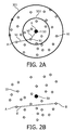
- a data collector node 50 surrounded by a plurality of nodes 10 is shown, illustrating multi-hop unicast data transmission from a sender node A to the data collector node 50 (destination node B) via a plurality of intermediate nodes N1...Ni.
- the nodes 10 have different hop distances to the data collector node 50 as indicated by radius 501 and 502. For instance, a node A within radius 501, but outside radius 502 will need two hops h1 and h2 for transmitting data packets to the data collector node 50 being the destination node B, i.e. a data packet has to be transmitted from this node A to the data collector node 50 via an intermediate node N1.
- a node 10 within radius 502 can transmit its data packets directly in one hop to the data collector node 50.
- the destination node B can be any node 10 and is not necessarily a data collector node 50.
- a hop distance can be defined for every pair of a sender node A and a destination node B.
- a parameter for characterizing the hop distance is the hop count, i.e. the number of hops required to transmit the data packet from the sender node A to the destination node B.
- a Euclidean distance d between the sender node A and the destination node B is illustrated. Between any two nodes 10, the Euclidean distance is defined as the geometric distance between two points. If the network addresses of the nodes 10 are based on GPS positions of the respective nodes 10, also a GPS-based distance may be used. The distance between two nodes 10 is then defined as the distance between their GPS positions. In particular, when the nodes 10 of the network are equally distributed over the network area, a Euclidean or GPS-based distance between two nodes can be characteristic for the number of hops performed on average when transmitting a data packet between two nodes and thus also for the transmission time. Alternatively, the distance can refer to the actual distance traveled by the data packet.
- a distance measured along streets can be used, rather than a Euclidian distance, since data packets will likely travel along these paths.
- This is illustrated in fig. 2C, showing street luminaire nodes 10 arranged along streets.
- the distance between two luminaire nodes 10 can also refer to a street distance, which is defined as the spatial distance or the hop distance along streets of a road system.
- a device 100 according to the present invention is shown.
- the device 100 can be associated with a node 10 or data collector node 50 of a wireless multi-hop mesh network, e.g. to luminaires of a lighting system.
- the device 100 comprises a control unit 200.
- either the node 10 or 50 or the device 100 comprises a transceiving unit 300 for transmitting or receiving data packets via wireless communication paths 40, e.g. via radio-frequency transmission.
- the control unit 200 of the device 100 may be sub-divided into different layers according to its functions in data packet transmission. For instance, when using an OSI-layer model, the control unit 200 will comprise a physical layer for defining the interaction of the device 100 with a transmission medium, a MAC layer providing addressing and channel access control mechanisms in a multi-node network, a network layer providing a plurality of functions and procedures, e.g. network routing functions, a transport layer providing reliable data transfer services to higher protocol layers using e.g. flow control, segmentation/desegmentation or error control and an application layer for identifying communication partners, determining resource availability or synchronizing communication.
- any node 10 may act as an intermediate Ni forwarding a received data packet to the next intermediate node Ni or to the final destination node B.
- the data packet When a long-traveled data packet is dropped at an intermediate node Ni, the data packet will have to be retransmitted by its sender node A (end-to-end retransmission), which at least doubles the accumulated end-to-end delay and the spending of network resources, i.e. system bandwidth. Therefore, according to one embodiment of the present invention, it is suggested that transmission parameters for processing a data packet to be forwarded are adjusted in an intermediate node Ni based on a traveled distance of the data packet.
- a flow diagram is shown, illustrating the adjustment of transmission parameters for a data packet to be forwarded.
- a data packet is received at the intermediate node Ni, either from the sender node A or from another intermediate node Ni.
- the distance between the receiving intermediate node Ni and the sender node A is determined (S41). Based on this distance, the transmission parameters for the data packet are adjusted (S42) and the data packet is processed using these transmission parameters (S43). This may for instance influence an order of a data packet queue, a priority rank parameter, etc., so that a long-traveled data packet may be processed faster.
- the data packet is forwarded to the next node 10 (S44) using the determined transmission parameters.
- the transmission parameters can refer to MAC parameters, e.g. a maximum number of MAC-layer retransmissions, a maximum number of channel access attempts, a transmit power level, a delay time for retransmission or a back-off time interval for channel access, or a combination thereof.
- the maximum number of MAC-layer retransmissions determines how often the MAC layer is allowed to retry the transmission of a data packet.
- the maximum number of channel access attempts relates to the maximum allowed number of times that a MAC layer is allowed to perform carrier sensing in order to get channel access for transmitting a data packet.
- the transmit power level refers to the transmission energy used for the data packet to be forwarded and is thus strongly related to the signal strength of the data packet.
- the delay time for retransmission denotes a delay between subsequent transmission attempts of a data packet and the back-off time interval for channel access refers to a time interval between two subsequent channel access attempts.
- the transmission parameters can be adjusted such, that a probability for a long-traveled data packet to successfully pass the final hops to its destination is increased. For instance, the maximum number of MAC layer retransmissions or the maximum number of channel access attempts or the transmit power level can be increased or the delay time for retransmission or the back-off time interval for channel access can be reduced. Of course, also a combination of these adjustments can be chosen.
- the intermediate node Ni can determine the distance traveled by the data packet based on local information stored in the intermediate node or on information included in the data packet.
- the distance between two nodes can be defined using a metric, such as a hop distance, a GPS-based distance or a Euclidean distance.
- the distance information can be derived therefrom.
- the distance can be derived based on a hop distance between the sender node A and the intermediate node Ni.
- the hop distance is characterized by the number of hops (hop count) a data packet has traveled from the sender node A.
- the hop distance information is already available at a network layer, e.g. when using routing tables with hop count metric. In this case, sender nodes A together with the respective distances from the intermediate node Ni are stored in the intermediate node Ni.
- the distance information can also be explicitly generated, e.g. by the network layer, using a hop counter or a time-to-live counter included in a data packet.
- the hop counter included in the data packet is increased every hop during the multi-hop transmission from the sender node A to the destination node B.
- the intermediate node Ni may then derive the hop distance information from the hop counter, i.e. a hop count.
- the hop count can also relate to the mean or average hop count over the last n data packets received from the sender node A.
- the hop count may be chosen as the maximum hop count of the last n data packets received from sender node A or as a sliding-window-average of hop counts of the last n data packets over time.
- the hop count information can be stored at the network layer for determining the hop distance for this sender node A.
- a time-to-live counter can be used.
- the time-to-live counter (TTL) is a header field with an initial value that is greater than the maximum required number of hops.
- TTL time-to-live counter
- the time-to-live counter is decreased. Data packets with a current time-to-live counter of zero will be dropped in order to avoid infinite forwarding of undeliverable data packets.
- a hop count can be derived from the difference between an initial time-to-live count before the first hop and a final time-to-live count when receiving the data packet.
- the intermediate node Ni either knows the initial value of the time-to-live counter or the initial time-to-live count is embedded in the data packet.
- a local clock signal of the intermediate node may be used as a reference to be compared with a start time or transmission time stamp, which indicates the start of the transmission at the sender node A.
- a travel time can be derived and thus, when using an average transmission speed, also the distance traveled by the data packet.
- distance information and in particular, hop count information can also be generated by the use of other techniques for building-up routing tables, e.g. by regularly sending beacon messages.
- an intermediate node Ni can identify a distance traveled by a data packet, e.g. on the basis of a hop counter or of a sender address included in the data packet.
- Long-traveled data packets exhibit high hop count values or a large difference between the GPS positions of the sender node A (e.g. indicated in the sender address field) and of the intermediate node Ni (at least known locally to the intermediate node Ni).
- the distance to be traveled i.e. the distance between the sender node A and the destination node B, may be included in the data packet.
- the distance traveled can be calculated as the distance between the sender node A and the destination node B minus the distance between the intermediate node Ni and the destination node B.
- the end-to-end delay can be decreased close to the minimum possible value and homogenized over the network.
- the adjustment of the transmission parameters is applicable to dynamic routing protocols, wherein the number of hops from a certain sender node A can vary.
- At least two sets of transmission parameters are stored in the intermediate node Ni, one relating to normal processing or forwarding of a data packet, the other relating to privileged processing or forwarding.
- the preferential transmission parameters for the hop of the data package to the next node 10 are chosen. This can for example be indicated by setting a flag in the data packet.
- the transmission parameters can also be adjusted in more than two levels.
- the adjustment of the transmission parameters may be proportional to the distance traveled by the data packet.
- a type of the data packet may be determined as additional parameter influencing the adjustment of the transmission parameters.
- the transmission parameters for long-traveled time-critical data packets may be adjusted to more favorable transmission parameters that particularly accelerate the processing and the transmission than shorter traveled time-uncritical data packets. Possibly, even a priority rank included in the data packet may be considered for the adjustment of the transmission parameters. Consequently, long-traveled data packets are more likely than shorter traveled data packets to successfully hop to the next node 10. This may even occur at the expense of short-traveled data packets and thereby result in delay homogenization.
- the answer time-out should take a value as small as possible in order to minimize the end-to-end communication delay.
- the answer time-out refers to the time period, for which any sender node A waits for an answer for the sent data packet from the destination node B before retransmitting the data packet.
- the answer may include an acknowledgement indicating successful transmission of the data packet sent by the sender node A or data requested by the sender node A or both. If the answer includes an acknowledgement, the answer time-out is also referred to acknowledgement time-out. In the prior art, the acknowledgement time-out is fixed and common for all nodes 10.
- the communication delay for closely neighbored nodes 10 is equal to the one for distant nodes 10, possibly resulting in unnecessary delays of data packet retransmissions. Therefore, according to a further embodiment of the present invention, the answer time-out for a data packet is adjusted based on a distance to be traveled by the data packet, i.e. the distance between the sender node A and the destination node B, as illustrated in Fig. 5 using the example of adjusting an acknowledgement time-out.
- S50 When processing a data packet to be sent or when sending a data packet (S50), the distance between the sender node A and the destination node B is determined (S51). Based on this distance, the acknowledgement time-out for this data packet is adjusted (S52).
- the acknowledgement time-out of a sender node A can be optimized, thus minimizing the end-to-end communication delay.
- the minimum value of the acknowledgement time-out equals the expected or average roundtrip time for a data packet transmission between the source node and the destination node, i.e. the time for delivery of the data packet plus the time for delivery of the acknowledgement.
- the minimum value of the answer time-out can be set to the minimum value of the roundtrip time or the like.
- the sender node A When the sender node A does not receive an acknowledgement for the sent data packet within the acknowledgement time-out, the sender node A will retransmit the data packet (S53).
- the order of the steps may be changed, i.e. steps S51 and/or S52 can be performed before sending the data packet (S50).
- the sender node A can determine the distance to the destination node B either from data stored in the sender node A, e.g. a routing table, a list of distances to potential destination nodes, distance information received before from the destination node B or the like.
- the sender node A may determine the distance to the destination node B from a hop counter or a time-to-live counter included in a data packet received from the destination node B.
- the hop count derived from a data packet or the mean or maximum hop count derived from the last n data packets received from destination node B may be used for the reverse path.
- the factor 2 is for the round trip, since the hop count only relates to one way.
- a hop count for the round trip may be used instead.
- the acknowledgement time-out is greater than or equal to the average roundtrip time.
- the hop_time can relate to an average time period required on average for forwarding a data packet to the next intermediate node Ni in a multi-hop transmission. This may be characteristic for the network. Again, the hop time may depend on the type of the data packet, e.g.
- the hop_time can also be replaced with other characteristic times, for instance a medium hop time or a success hop time, i.e. a time interval, in which a certain percentage, e.g. 90% -99% of the hops are successfully taken.
- a success hop time i.e. a time interval, in which a certain percentage, e.g. 90% -99% of the hops are successfully taken.
- the acknowledgement time-out is similarly calculated using a characteristic time for the chosen metric.
- the answer time-out can additionally be based on a current traffic load in the network, which will result in a higher hop time. This can be determined e.g. by an amount of network traffic observed or received by the sender node A, or by how many packets the sender node A sent out in the last time period T.
- the receiver node B (or any of the intermediate nodes Ni) can report information about a network load to the sender node A, e.g. as part of a data packet or together with an acknowledgement.
- transmission parameters are adjusted based on a traveled distance of a data packet, this can be additionally considered for the adjustment of the answer time-out.
- Adjusting the transmission parameters or the answer time-out is not only applicable to unicast data packets sent to only one destination node B.
- the embodiment can also be applied in broadcast and multicast cases, wherein a data packet is transmitted to several destination nodes B. In these cases, different sets of transmission parameters or different answer time-outs for different destination nodes B in a multicast group can be taken into account, e.g. the maximum acknowledgement time-out for the nodes in the group is selected.
- the delay for operation commands can thus be minimized.
- the transmission parameters of the intermediate node Ni can be adjusted for the data packet based on the distance travelled by this data packet.
- the survival chance of long-travelled data packets is increased, thus reducing the end-to-end communication delay.
- data packets perceive comparable delays irrespective of the required number of hops, which is beneficial for an application and also for a transport layer. This is in particular useful, if data packets have to be retransmitted at higher layers in case of data packet loss.
- a reduced mean and maximum delay can be achieved as well as higher delay homogeneity in the network.
- the answer time-out can be adjusted for each individual pair of sender node A and destination node B, further reducing the end-to-end transmission delay in a wireless network.
- overall network resources can be saved.
Landscapes
- Engineering & Computer Science (AREA)
- Computer Networks & Wireless Communication (AREA)
- Signal Processing (AREA)
- Health & Medical Sciences (AREA)
- Computing Systems (AREA)
- General Health & Medical Sciences (AREA)
- Medical Informatics (AREA)
- Databases & Information Systems (AREA)
- Mobile Radio Communication Systems (AREA)
Claims (7)
- Système pour commander des transmissions de paquets de données dans un réseau sans fil, le système comprenant :un centre de commande (60) etune pluralité de nœuds (10, 50), au moins certains d'entre eux comprenant un dispositif (100) pour commander des transmissions de paquets de données dans un réseau sans fil possédant une pluralité de nœuds (10, 50),dans lequel les nœuds (10, 50) sont associés à des luminaires d'un système d'éclairage, etdans lequel les paquets de données sont transmis d'un nœud expéditeur (A) vers un nœud de destination via des nœuds intermédiaires (Ni) par des transmissions à sauts multiples dans le réseau sans fil,le dispositif (100) comprenantune unité de commande (200) qui est adaptée pour ajuster des paramètres de transmission d'un nœud intermédiaire (Ni) pour acheminer un paquet de données reçu par le nœud intermédiaire (Ni) en fonction d'une distance, entre le nœud intermédiaire (Ni) et le nœud expéditeur (A), parcourue par le paquet de données,caractérisé en ce queles paramètres de transmission sont réglés à des paramètres de transmission préférentiels pour le paquet de données, s'il est déterminé que la distance parcourue par le paquet de données excède un seuil prédéterminé,dans lequel les paramètres de transmission sont ajustés de sorte qu'une probabilité de transmission de paquets de données ayant parcouru une distance excédant un seuil prédéterminé est augmentée,dans lequel la distance entre deux nœuds (10, 50) est définie par une distance à base de GPS et/ou euclidienne, etdans lequel la distance parcourue par le paquet de données provient d'une localisation GPS du nœud expéditeur (A).
- Système selon la revendication 1, dans lequel le dispositif (100) est adapté pour être couplé à un nœud (10) et/ou à un nœud collecteur de données (50) et/ou dans lequel le réseau sans fil est un réseau maillé et/ou dans lequel une transmission de paquet de données du nœud expéditeur (A) à un nœud de destination (B) est réalisée dans un mode à sauts multiples par l'intermédiaire d'une pluralité de nœuds intermédiaires (Ni).
- Système selon l'une quelconque des revendications précédentes, dans lequel les paramètres de transmission comprennent au moins l'un parmi un nombre maximum de retransmissions à une couche inférieure, un nombre maximum de tentatives d'accès au support, un niveau de puissance de transmission, un temps d'attente pour la retransmission et un temps de réduction de puissance pour des tentatives d'accès au support.
- Système selon l'une quelconque des revendications précédentes, dans lequel les paramètres de transmission sont ajustés en continu en fonction de la distance parcourue par le paquet de données et/ou dans lequel les paramètres de transmission sont ajustés en fonction d'un type du paquet de données.
- Système selon l'une quelconque des revendications précédentes, dans lequel des informations de distance sont fournies d'une couche inférieure à une couche supérieure par communication croisée entre couches.
- Système selon l'une des revendications précédentes, dans lequel le dispositif (100) est utilisé dans la télégestion d'un système d'éclairage pour l'allumage/l'arrêt et/ou la commande de modes de réalisation de gradation de l'intensité lumineuse de nœuds de luminaire (10, 50), et/ou le rapport de données de capteur et/ou d'état de luminaire.
- Système selon l'une des revendications précédentes, dans lequel l'unité de commande (200) est en outre adaptée, lorsque le dispositif sert de nœud expéditeur (A), pour ajuster un délai d'attente de réponse pour un paquet de données destiné à être envoyé en fonction d'une distance d'un nœud expéditeur (A) à un nœud de destination (B).
Priority Applications (2)
| Application Number | Priority Date | Filing Date | Title |
|---|---|---|---|
| PL11764326T PL2622800T5 (pl) | 2010-10-01 | 2011-09-09 | Układ optymalizacji opóźnienia pełnych przesyłów pakietów danych w sieciach bezprzewodowych |
| EP11764326.2A EP2622800B2 (fr) | 2010-10-01 | 2011-09-09 | Système pour optimiser le délai de la transmission de paquet de données de bout en bout dans des réseaux sans fil |
Applications Claiming Priority (3)
| Application Number | Priority Date | Filing Date | Title |
|---|---|---|---|
| EP20100185952 EP2437440A1 (fr) | 2010-10-01 | 2010-10-01 | Dispositif et procédé pour optimiser le délai de la transmission de paquet de données de bout en bout dans des réseaux sans fil |
| EP11764326.2A EP2622800B2 (fr) | 2010-10-01 | 2011-09-09 | Système pour optimiser le délai de la transmission de paquet de données de bout en bout dans des réseaux sans fil |
| PCT/IB2011/053940 WO2012042411A1 (fr) | 2010-10-01 | 2011-09-09 | Dispositif et procédé pour une optimisation du retard de bout en bout de transmissions de paquets de données dans des réseaux sans fil |
Publications (3)
| Publication Number | Publication Date |
|---|---|
| EP2622800A1 EP2622800A1 (fr) | 2013-08-07 |
| EP2622800B1 EP2622800B1 (fr) | 2017-08-23 |
| EP2622800B2 true EP2622800B2 (fr) | 2020-03-18 |
Family
ID=43064852
Family Applications (2)
| Application Number | Title | Priority Date | Filing Date |
|---|---|---|---|
| EP20100185952 Ceased EP2437440A1 (fr) | 2010-10-01 | 2010-10-01 | Dispositif et procédé pour optimiser le délai de la transmission de paquet de données de bout en bout dans des réseaux sans fil |
| EP11764326.2A Active EP2622800B2 (fr) | 2010-10-01 | 2011-09-09 | Système pour optimiser le délai de la transmission de paquet de données de bout en bout dans des réseaux sans fil |
Family Applications Before (1)
| Application Number | Title | Priority Date | Filing Date |
|---|---|---|---|
| EP20100185952 Ceased EP2437440A1 (fr) | 2010-10-01 | 2010-10-01 | Dispositif et procédé pour optimiser le délai de la transmission de paquet de données de bout en bout dans des réseaux sans fil |
Country Status (7)
| Country | Link |
|---|---|
| US (1) | US9119142B2 (fr) |
| EP (2) | EP2437440A1 (fr) |
| JP (1) | JP6118252B2 (fr) |
| CN (1) | CN103119898B (fr) |
| PL (1) | PL2622800T5 (fr) |
| TW (1) | TW201218696A (fr) |
| WO (1) | WO2012042411A1 (fr) |
Families Citing this family (40)
| Publication number | Priority date | Publication date | Assignee | Title |
|---|---|---|---|---|
| US9615316B2 (en) | 2011-11-18 | 2017-04-04 | Qualcomm Incorporated | Methods and devices for facilitating modified cell reselection parameters and procedures when access terminals exhibit little or no mobility |
| KR101458852B1 (ko) * | 2012-02-10 | 2014-11-12 | 폴리콤 인코포레이티드 | 멀티-홉 rtp 스트림에서의 중요 패킷 손실 처리 시스템 및 방법 |
| JP6048502B2 (ja) * | 2012-07-23 | 2016-12-21 | 富士通株式会社 | 通信装置 |
| US9461926B2 (en) | 2012-10-01 | 2016-10-04 | Abb Research Ltd | Packet prioritizing in an industrial wireless network |
| CN103916448B (zh) * | 2013-01-09 | 2018-05-18 | 深圳市腾讯计算机系统有限公司 | 基于云传输平台的数据传输方法、系统及相应的云传输平台 |
| US9509636B2 (en) * | 2013-03-15 | 2016-11-29 | Vivint, Inc. | Multicast traffic management within a wireless mesh network |
| US8879613B1 (en) | 2013-08-06 | 2014-11-04 | Cisco Technology, Inc. | Dynamic frame selection when requesting tone map parameters in mesh networks |
| JP6244744B2 (ja) * | 2013-08-28 | 2017-12-13 | 株式会社リコー | 通信装置、通信方法及び通信システム |
| US9712332B2 (en) | 2014-03-11 | 2017-07-18 | Vivint, Inc. | Node directed multicast traffic management systems and methods for mesh networks |
| US20170048167A1 (en) * | 2014-04-30 | 2017-02-16 | Hewlett Packard Enterprise Development Lp | Flood disable on network switch |
| US9923836B1 (en) * | 2014-11-21 | 2018-03-20 | Sprint Spectrum L.P. | Systems and methods for configuring a delay based scheduler for an access node |
| FR3030991B1 (fr) * | 2014-12-22 | 2018-03-23 | Commissariat A L'energie Atomique Et Aux Energies Alternatives | Reseau de dispositifs de mesure communiquant par liaison radio |
| CN104734808B (zh) * | 2015-03-07 | 2018-05-29 | 浙江理工大学 | 一种无线传感网络中最差时延感知跨层优化方法 |
| DE102015207985A1 (de) * | 2015-04-30 | 2016-11-03 | Zumtobel Lighting Gmbh | Verfahren und System zur Übermittlung von Steuerbefehlen für verteilt angeordnete Einheiten |
| CN104967813A (zh) * | 2015-07-04 | 2015-10-07 | 马岩 | 视频会议的超时重发方法及系统 |
| KR102419647B1 (ko) * | 2015-09-10 | 2022-07-11 | 삼성전자주식회사 | 패킷을 전송하는 장치 및 방법 |
| CN105263121B (zh) * | 2015-09-17 | 2018-10-12 | 重庆邮电大学 | 一种机会车载网络中基于十字路口的路由方法 |
| US10027581B2 (en) * | 2015-10-19 | 2018-07-17 | Cisco Technology, Inc. | Routing traffic over chaotic networks |
| CN105897582A (zh) * | 2015-12-07 | 2016-08-24 | 乐视云计算有限公司 | 节点间距离的度量方法及系统 |
| US20170163509A1 (en) * | 2015-12-07 | 2017-06-08 | Le Holdings (Beijing) Co., Ltd. | Inter-node distance metric method and system |
| SE540352C2 (en) * | 2016-01-29 | 2018-07-24 | Icomera Ab | Wireless communication system and method for trains and other vehicles using trackside base stations |
| DE102016102525A1 (de) * | 2016-02-15 | 2017-08-17 | Hella Kgaa Hueck & Co. | Kommunikationssystem zur Datenkommunikation mit wenigstens einem Fahrzeug im Straßenverkehr |
| US9900079B2 (en) * | 2016-03-21 | 2018-02-20 | Cisco Technology, Inc. | Reliable connectionless low power coverage extension |
| JP6635866B2 (ja) * | 2016-04-20 | 2020-01-29 | 大阪瓦斯株式会社 | 無線通信システム |
| GB2565987B (en) * | 2016-07-29 | 2021-08-18 | Motorola Solutions Inc | Wireless ad-hoc network flooding mechanism to intelligently locate required responders |
| WO2018030923A1 (fr) * | 2016-08-10 | 2018-02-15 | Telefonaktiebolaget Lm Ericsson (Publ) | Retransmission de paquets dans un réseau maillé sans fil |
| WO2018031951A1 (fr) * | 2016-08-11 | 2018-02-15 | Hopzero, Inc. | Procédé et système pour limiter la gamme de transmissions de données |
| DE102016125636A1 (de) * | 2016-12-23 | 2018-06-28 | Osram Gmbh | Betreiben von einer Sendeeinrichtung einer eine Leuchteinrichtung aufweisenden Beleuchtungseinrichtung |
| EP3367613A1 (fr) * | 2017-02-28 | 2018-08-29 | ABB Schweiz AG | Système et procédé pour améliorer la latence dans un réseau sans fil d'automatisation de bâtiment |
| EP3701657B1 (fr) * | 2017-10-27 | 2022-08-03 | Telefonaktiebolaget LM Ericsson (PUBL) | Procédé et dispositif de mise à jour du nombre de retransmissions dans un réseau maillé sans fil |
| CN109905897B (zh) * | 2017-12-08 | 2022-11-18 | 华为技术有限公司 | 数据传输的方法和装置 |
| US10944669B1 (en) | 2018-02-09 | 2021-03-09 | GoTenna, Inc. | System and method for efficient network-wide broadcast in a multi-hop wireless network using packet echos |
| KR102107392B1 (ko) * | 2018-02-28 | 2020-05-07 | 주식회사 노비스텍 | 가로등 무선원격 관제시스템 |
| CA3107919A1 (fr) | 2018-07-27 | 2020-01-30 | GoTenna, Inc. | Routage de paquets a commande nulle vine a l'aide d'une inspection de p aquets de donnees pour des reseaux mailles sans fil |
| CN109039906B (zh) * | 2018-10-24 | 2020-10-30 | 常熟理工学院 | 一种智能车联网的路由实现方法 |
| US10754559B1 (en) * | 2019-03-08 | 2020-08-25 | EMC IP Holding Company LLC | Active-active storage clustering with clock synchronization |
| US10602402B1 (en) * | 2019-08-28 | 2020-03-24 | Ambit Microsystems (Shanghai) Ltd. | Method and system for adjusting packet length and mobile device using the method |
| JP7364539B2 (ja) * | 2020-08-03 | 2023-10-18 | 本田技研工業株式会社 | ネットワーク管理装置、ネットワーク管理方法、及びプログラム |
| US11758367B2 (en) * | 2021-05-10 | 2023-09-12 | Cisco Technology, Inc. | Multicast tree topology having multicast hubs for different multicast areas in a Wi-SUN FAN data network |
| CN113938859B (zh) * | 2021-12-13 | 2022-03-15 | 深圳市永达电子信息股份有限公司 | 用于移动设备的集中式和分散式通信的集成系统和方法 |
Family Cites Families (30)
| Publication number | Priority date | Publication date | Assignee | Title |
|---|---|---|---|---|
| DE19849294C2 (de) * | 1998-10-16 | 2001-09-27 | Daimler Chrysler Ag | Verfahren zum Verbreiten einer Nachricht |
| US6405337B1 (en) * | 1999-06-21 | 2002-06-11 | Ericsson Inc. | Systems, methods and computer program products for adjusting a timeout for message retransmission based on measured round-trip communications delays |
| JP3539338B2 (ja) * | 2000-03-23 | 2004-07-07 | 日本電気株式会社 | 優先データ転送方法 |
| US6958998B2 (en) | 2001-07-09 | 2005-10-25 | International Business Machines Corporation | Traffic management in packet-based networks |
| US8571415B1 (en) * | 2001-07-19 | 2013-10-29 | Alcatel Lucent | Regenerators placement mechanism for wavelength switched optical networks |
| EP1300990B1 (fr) * | 2001-10-02 | 2007-08-08 | Siemens Aktiengesellschaft | Procédé et appareil de communication pour fournir une qualité de service en fonction de la distance dans un système de communication |
| JP4535661B2 (ja) | 2002-03-18 | 2010-09-01 | 日本電気株式会社 | 無線マルチホップネットワークにおける送信ノード、中継ノード及び通信システム |
| EP1733587B1 (fr) * | 2004-03-30 | 2012-08-01 | Telefonaktiebolaget LM Ericsson (publ) | Procedes et appareils de transfert a repartition de cellules dans un systeme de telecommunications mobiles |
| US7466664B2 (en) * | 2005-09-02 | 2008-12-16 | Palo Alto Research Center Incorporated | Methods, apparatus, and program products for applying a visibility function to networked information |
| US7768926B2 (en) * | 2006-03-09 | 2010-08-03 | Firetide, Inc. | Effective bandwidth path metric and path computation method for wireless mesh networks with wired links |
| JP2007335943A (ja) * | 2006-06-12 | 2007-12-27 | Nippon Telegr & Teleph Corp <Ntt> | 無線基地局およびマルチホップ制御方法 |
| KR100789773B1 (ko) * | 2006-12-08 | 2007-12-28 | 한국전자통신연구원 | 다중 홉 무선 근거리통신망에서 메쉬 네트워킹 자동 설정방법과, 가상 링크 설정 방법과, 패킷 전송 방법 및 이를위한 무선 단말기 |
| JP2008167141A (ja) * | 2006-12-28 | 2008-07-17 | Nec Corp | データ伝送方法および装置、それを用いた通信システム |
| KR100832519B1 (ko) * | 2007-03-13 | 2008-05-26 | (주)에스디시스템 | 무선태그를 이용한 조명제어시스템 및 그 방법 |
| KR20090056070A (ko) * | 2007-11-29 | 2009-06-03 | 대구대학교 산학협력단 | 차량 애드혹네트워크에서 경쟁윈도우를 이용한 릴레이노드선정방법 |
| JP2011507322A (ja) | 2007-12-05 | 2011-03-03 | トムソン ライセンシング | 通信ネットワークにおける通信リンクを特徴付ける方法 |
| KR20090065230A (ko) | 2007-12-17 | 2009-06-22 | 한국전자통신연구원 | 계층 구조를 갖는 무선 센서망 및 이를 위한 라우팅 방법 |
| US8301955B2 (en) | 2008-01-15 | 2012-10-30 | Avaya Inc. | Method and apparatus performing express retransmission of frames |
| US8345607B2 (en) * | 2008-03-10 | 2013-01-01 | Marvell World Trade Ltd. | Coexistence and collocation of remote network and local network radios |
| ES2326949B1 (es) * | 2008-03-18 | 2010-07-14 | Clarity Systems, S.L. | Procedimiento utilizado por un servidor de streaming para realizar una transmision de un fichero multimedia en una red de datos. |
| CN101631357A (zh) * | 2008-07-18 | 2010-01-20 | 中国移动通信集团公司 | 一种选择性应答分组传输方法、装置及终端 |
| US8483077B2 (en) * | 2009-09-16 | 2013-07-09 | At&T Intellectual Property I, L.P. | QoS in multi-hop wireless networks |
| CN101651963B (zh) | 2009-07-09 | 2012-05-23 | 南京工业大学 | 一种ieee 802.11 wlan中基于区分服务的传输控制方法 |
| JP5589410B2 (ja) * | 2010-01-29 | 2014-09-17 | 沖電気工業株式会社 | 通信システム及び通信装置 |
| WO2011145027A1 (fr) | 2010-05-21 | 2011-11-24 | Koninklijke Philips Electronics N.V. | Procédé et dispositif permettant de transférer des paquets de données |
| EP2622775B1 (fr) | 2010-10-01 | 2014-02-26 | Koninklijke Philips N.V. | Dispositif et procédé pour programmer des transmissions de paquets de données dans des réseaux sans fil |
| EP2437428A1 (fr) | 2010-10-01 | 2012-04-04 | Koninklijke Philips Electronics N.V. | Dispositif et procédé pour l'équilibrage de charge pour la transmission de paquets de données dans des réseaux sans fil |
| WO2012042426A1 (fr) | 2010-10-01 | 2012-04-05 | Koninklijke Philips Electronics N.V. | Dispositif et procédé pour améliorer la fiabilité de transmissions de paquets de données dans des réseaux sans fil |
| WO2012052804A1 (fr) * | 2010-10-20 | 2012-04-26 | Nokia Corporation | Procédé et appareil pour limiter l'émission d'un canal adjacent |
| US20130155919A1 (en) * | 2011-12-20 | 2013-06-20 | Korea Basic Science Institute | Method of potential routing, method of potential scheduling, and mesh node |
-
2010
- 2010-10-01 EP EP20100185952 patent/EP2437440A1/fr not_active Ceased
-
2011
- 2011-09-09 JP JP2013530824A patent/JP6118252B2/ja active Active
- 2011-09-09 CN CN201180046862.2A patent/CN103119898B/zh active Active
- 2011-09-09 US US13/876,183 patent/US9119142B2/en active Active
- 2011-09-09 EP EP11764326.2A patent/EP2622800B2/fr active Active
- 2011-09-09 WO PCT/IB2011/053940 patent/WO2012042411A1/fr active Application Filing
- 2011-09-09 PL PL11764326T patent/PL2622800T5/pl unknown
- 2011-09-28 TW TW100135098A patent/TW201218696A/zh unknown
Also Published As
| Publication number | Publication date |
|---|---|
| PL2622800T3 (pl) | 2018-01-31 |
| US9119142B2 (en) | 2015-08-25 |
| JP2013543692A (ja) | 2013-12-05 |
| CN103119898A (zh) | 2013-05-22 |
| TW201218696A (en) | 2012-05-01 |
| JP6118252B2 (ja) | 2017-04-19 |
| PL2622800T5 (pl) | 2020-07-27 |
| CN103119898B (zh) | 2016-04-13 |
| EP2437440A1 (fr) | 2012-04-04 |
| EP2622800A1 (fr) | 2013-08-07 |
| EP2622800B1 (fr) | 2017-08-23 |
| US20130188562A1 (en) | 2013-07-25 |
| WO2012042411A1 (fr) | 2012-04-05 |
Similar Documents
| Publication | Publication Date | Title |
|---|---|---|
| EP2622800B2 (fr) | Système pour optimiser le délai de la transmission de paquet de données de bout en bout dans des réseaux sans fil | |
| JP5992421B2 (ja) | 無線ネットワークでデータパケットを負荷分散するデバイス及び方法 | |
| US10397823B2 (en) | Device and method for scheduling data packet transmission in wireless networks | |
| EP2643951B1 (fr) | Système et procédé d'optimisation d'une transmission de données à des n uds d'un réseau maillé sans fil | |
| JP5364728B2 (ja) | ローカル・ピア・グループ(lpg)に基づく車両アドホックネットワークにおける高信頼度マルチキャスト方法 | |
| US10219319B2 (en) | Device and method for controlling a node of a wireless network | |
| JP2014507828A (ja) | 通信ネットワークの少なくとも1つのアプリケーションのデータ通信を制御するためのコンポーネント、システム、及び方法 | |
| WO2012042454A1 (fr) | Dispositif et procédé permettant de réduire le retard des transmissions des paquets de données dans des réseaux sans fil | |
| WO2012042426A1 (fr) | Dispositif et procédé pour améliorer la fiabilité de transmissions de paquets de données dans des réseaux sans fil | |
| CN112567883A (zh) | 用于应用数据交换的方法和节点设备 |
Legal Events
| Date | Code | Title | Description |
|---|---|---|---|
| PUAI | Public reference made under article 153(3) epc to a published international application that has entered the european phase |
Free format text: ORIGINAL CODE: 0009012 |
|
| 17P | Request for examination filed |
Effective date: 20130502 |
|
| AK | Designated contracting states |
Kind code of ref document: A1 Designated state(s): AL AT BE BG CH CY CZ DE DK EE ES FI FR GB GR HR HU IE IS IT LI LT LU LV MC MK MT NL NO PL PT RO RS SE SI SK SM TR |
|
| RAP1 | Party data changed (applicant data changed or rights of an application transferred) |
Owner name: KONINKLIJKE PHILIPS N.V. |
|
| DAX | Request for extension of the european patent (deleted) | ||
| RAP1 | Party data changed (applicant data changed or rights of an application transferred) |
Owner name: PHILIPS LIGHTING HOLDING B.V. |
|
| REG | Reference to a national code |
Ref country code: DE Ref legal event code: R079 Ref document number: 602011040894 Country of ref document: DE Free format text: PREVIOUS MAIN CLASS: H04L0012560000 Ipc: H04L0012701000 |
|
| GRAP | Despatch of communication of intention to grant a patent |
Free format text: ORIGINAL CODE: EPIDOSNIGR1 |
|
| RIC1 | Information provided on ipc code assigned before grant |
Ipc: H04L 12/801 20130101ALI20170217BHEP Ipc: H04L 29/08 20060101ALI20170217BHEP Ipc: H04W 40/20 20090101ALI20170217BHEP Ipc: H04L 12/701 20130101AFI20170217BHEP Ipc: H04W 84/18 20090101ALI20170217BHEP |
|
| INTG | Intention to grant announced |
Effective date: 20170315 |
|
| GRAS | Grant fee paid |
Free format text: ORIGINAL CODE: EPIDOSNIGR3 |
|
| GRAA | (expected) grant |
Free format text: ORIGINAL CODE: 0009210 |
|
| RIN1 | Information on inventor provided before grant (corrected) |
Inventor name: ESPINA PEREZ, JAVIER Inventor name: GOERGEN, DANIEL MARTIN Inventor name: GARCIA MORCHON, OSCAR Inventor name: SCHENK, TIM CORNEEL WILHELMUS |
|
| AK | Designated contracting states |
Kind code of ref document: B1 Designated state(s): AL AT BE BG CH CY CZ DE DK EE ES FI FR GB GR HR HU IE IS IT LI LT LU LV MC MK MT NL NO PL PT RO RS SE SI SK SM TR |
|
| REG | Reference to a national code |
Ref country code: GB Ref legal event code: FG4D |
|
| REG | Reference to a national code |
Ref country code: CH Ref legal event code: EP |
|
| REG | Reference to a national code |
Ref country code: AT Ref legal event code: REF Ref document number: 922414 Country of ref document: AT Kind code of ref document: T Effective date: 20170915 |
|
| REG | Reference to a national code |
Ref country code: IE Ref legal event code: FG4D |
|
| REG | Reference to a national code |
Ref country code: FR Ref legal event code: PLFP Year of fee payment: 7 |
|
| REG | Reference to a national code |
Ref country code: DE Ref legal event code: R096 Ref document number: 602011040894 Country of ref document: DE |
|
| REG | Reference to a national code |
Ref country code: NL Ref legal event code: MP Effective date: 20170823 |
|
| REG | Reference to a national code |
Ref country code: LT Ref legal event code: MG4D |
|
| REG | Reference to a national code |
Ref country code: AT Ref legal event code: MK05 Ref document number: 922414 Country of ref document: AT Kind code of ref document: T Effective date: 20170823 |
|
| PG25 | Lapsed in a contracting state [announced via postgrant information from national office to epo] |
Ref country code: LT Free format text: LAPSE BECAUSE OF FAILURE TO SUBMIT A TRANSLATION OF THE DESCRIPTION OR TO PAY THE FEE WITHIN THE PRESCRIBED TIME-LIMIT Effective date: 20170823 Ref country code: SE Free format text: LAPSE BECAUSE OF FAILURE TO SUBMIT A TRANSLATION OF THE DESCRIPTION OR TO PAY THE FEE WITHIN THE PRESCRIBED TIME-LIMIT Effective date: 20170823 Ref country code: AT Free format text: LAPSE BECAUSE OF FAILURE TO SUBMIT A TRANSLATION OF THE DESCRIPTION OR TO PAY THE FEE WITHIN THE PRESCRIBED TIME-LIMIT Effective date: 20170823 Ref country code: FI Free format text: LAPSE BECAUSE OF FAILURE TO SUBMIT A TRANSLATION OF THE DESCRIPTION OR TO PAY THE FEE WITHIN THE PRESCRIBED TIME-LIMIT Effective date: 20170823 Ref country code: NO Free format text: LAPSE BECAUSE OF FAILURE TO SUBMIT A TRANSLATION OF THE DESCRIPTION OR TO PAY THE FEE WITHIN THE PRESCRIBED TIME-LIMIT Effective date: 20171123 Ref country code: HR Free format text: LAPSE BECAUSE OF FAILURE TO SUBMIT A TRANSLATION OF THE DESCRIPTION OR TO PAY THE FEE WITHIN THE PRESCRIBED TIME-LIMIT Effective date: 20170823 Ref country code: NL Free format text: LAPSE BECAUSE OF FAILURE TO SUBMIT A TRANSLATION OF THE DESCRIPTION OR TO PAY THE FEE WITHIN THE PRESCRIBED TIME-LIMIT Effective date: 20170823 |
|
| PG25 | Lapsed in a contracting state [announced via postgrant information from national office to epo] |
Ref country code: ES Free format text: LAPSE BECAUSE OF FAILURE TO SUBMIT A TRANSLATION OF THE DESCRIPTION OR TO PAY THE FEE WITHIN THE PRESCRIBED TIME-LIMIT Effective date: 20170823 Ref country code: GR Free format text: LAPSE BECAUSE OF FAILURE TO SUBMIT A TRANSLATION OF THE DESCRIPTION OR TO PAY THE FEE WITHIN THE PRESCRIBED TIME-LIMIT Effective date: 20171124 Ref country code: IS Free format text: LAPSE BECAUSE OF FAILURE TO SUBMIT A TRANSLATION OF THE DESCRIPTION OR TO PAY THE FEE WITHIN THE PRESCRIBED TIME-LIMIT Effective date: 20171223 Ref country code: LV Free format text: LAPSE BECAUSE OF FAILURE TO SUBMIT A TRANSLATION OF THE DESCRIPTION OR TO PAY THE FEE WITHIN THE PRESCRIBED TIME-LIMIT Effective date: 20170823 Ref country code: RS Free format text: LAPSE BECAUSE OF FAILURE TO SUBMIT A TRANSLATION OF THE DESCRIPTION OR TO PAY THE FEE WITHIN THE PRESCRIBED TIME-LIMIT Effective date: 20170823 Ref country code: BG Free format text: LAPSE BECAUSE OF FAILURE TO SUBMIT A TRANSLATION OF THE DESCRIPTION OR TO PAY THE FEE WITHIN THE PRESCRIBED TIME-LIMIT Effective date: 20171123 |
|
| PG25 | Lapsed in a contracting state [announced via postgrant information from national office to epo] |
Ref country code: CZ Free format text: LAPSE BECAUSE OF FAILURE TO SUBMIT A TRANSLATION OF THE DESCRIPTION OR TO PAY THE FEE WITHIN THE PRESCRIBED TIME-LIMIT Effective date: 20170823 Ref country code: DK Free format text: LAPSE BECAUSE OF FAILURE TO SUBMIT A TRANSLATION OF THE DESCRIPTION OR TO PAY THE FEE WITHIN THE PRESCRIBED TIME-LIMIT Effective date: 20170823 Ref country code: RO Free format text: LAPSE BECAUSE OF FAILURE TO SUBMIT A TRANSLATION OF THE DESCRIPTION OR TO PAY THE FEE WITHIN THE PRESCRIBED TIME-LIMIT Effective date: 20170823 |
|
| REG | Reference to a national code |
Ref country code: CH Ref legal event code: PL |
|
| REG | Reference to a national code |
Ref country code: DE Ref legal event code: R026 Ref document number: 602011040894 Country of ref document: DE |
|
| PLBI | Opposition filed |
Free format text: ORIGINAL CODE: 0009260 |
|
| PG25 | Lapsed in a contracting state [announced via postgrant information from national office to epo] |
Ref country code: SM Free format text: LAPSE BECAUSE OF FAILURE TO SUBMIT A TRANSLATION OF THE DESCRIPTION OR TO PAY THE FEE WITHIN THE PRESCRIBED TIME-LIMIT Effective date: 20170823 Ref country code: EE Free format text: LAPSE BECAUSE OF FAILURE TO SUBMIT A TRANSLATION OF THE DESCRIPTION OR TO PAY THE FEE WITHIN THE PRESCRIBED TIME-LIMIT Effective date: 20170823 Ref country code: MC Free format text: LAPSE BECAUSE OF FAILURE TO SUBMIT A TRANSLATION OF THE DESCRIPTION OR TO PAY THE FEE WITHIN THE PRESCRIBED TIME-LIMIT Effective date: 20170823 Ref country code: SK Free format text: LAPSE BECAUSE OF FAILURE TO SUBMIT A TRANSLATION OF THE DESCRIPTION OR TO PAY THE FEE WITHIN THE PRESCRIBED TIME-LIMIT Effective date: 20170823 |
|
| PLAX | Notice of opposition and request to file observation + time limit sent |
Free format text: ORIGINAL CODE: EPIDOSNOBS2 |
|
| 26 | Opposition filed |
Opponent name: MOLNIA, DAVID Effective date: 20180523 |
|
| REG | Reference to a national code |
Ref country code: IE Ref legal event code: MM4A |
|
| REG | Reference to a national code |
Ref country code: BE Ref legal event code: MM Effective date: 20170930 |
|
| PG25 | Lapsed in a contracting state [announced via postgrant information from national office to epo] |
Ref country code: LU Free format text: LAPSE BECAUSE OF NON-PAYMENT OF DUE FEES Effective date: 20170909 |
|
| PG25 | Lapsed in a contracting state [announced via postgrant information from national office to epo] |
Ref country code: CH Free format text: LAPSE BECAUSE OF NON-PAYMENT OF DUE FEES Effective date: 20170930 Ref country code: LI Free format text: LAPSE BECAUSE OF NON-PAYMENT OF DUE FEES Effective date: 20170930 Ref country code: IE Free format text: LAPSE BECAUSE OF NON-PAYMENT OF DUE FEES Effective date: 20170909 |
|
| PG25 | Lapsed in a contracting state [announced via postgrant information from national office to epo] |
Ref country code: SI Free format text: LAPSE BECAUSE OF FAILURE TO SUBMIT A TRANSLATION OF THE DESCRIPTION OR TO PAY THE FEE WITHIN THE PRESCRIBED TIME-LIMIT Effective date: 20170823 Ref country code: BE Free format text: LAPSE BECAUSE OF NON-PAYMENT OF DUE FEES Effective date: 20170930 |
|
| REG | Reference to a national code |
Ref country code: FR Ref legal event code: PLFP Year of fee payment: 8 |
|
| PG25 | Lapsed in a contracting state [announced via postgrant information from national office to epo] |
Ref country code: MT Free format text: LAPSE BECAUSE OF NON-PAYMENT OF DUE FEES Effective date: 20170909 |
|
| PLBB | Reply of patent proprietor to notice(s) of opposition received |
Free format text: ORIGINAL CODE: EPIDOSNOBS3 |
|
| RAP2 | Party data changed (patent owner data changed or rights of a patent transferred) |
Owner name: PHILIPS LIGHTING HOLDING B.V. |
|
| RAP2 | Party data changed (patent owner data changed or rights of a patent transferred) |
Owner name: SIGNIFY HOLDING B.V. |
|
| PG25 | Lapsed in a contracting state [announced via postgrant information from national office to epo] |
Ref country code: HU Free format text: LAPSE BECAUSE OF FAILURE TO SUBMIT A TRANSLATION OF THE DESCRIPTION OR TO PAY THE FEE WITHIN THE PRESCRIBED TIME-LIMIT; INVALID AB INITIO Effective date: 20110909 |
|
| RIC2 | Information provided on ipc code assigned after grant |
Ipc: H04W 28/02 20090101ALI20190628BHEP Ipc: H04L 1/18 20060101AFI20190628BHEP Ipc: H04L 12/841 20130101ALI20190628BHEP Ipc: H04L 1/00 20060101ALI20190628BHEP Ipc: H04L 29/08 20060101ALI20190628BHEP Ipc: H04W 40/20 20090101ALI20190628BHEP Ipc: H04L 12/801 20130101ALI20190628BHEP |
|
| PG25 | Lapsed in a contracting state [announced via postgrant information from national office to epo] |
Ref country code: CY Free format text: LAPSE BECAUSE OF NON-PAYMENT OF DUE FEES Effective date: 20170823 |
|
| PG25 | Lapsed in a contracting state [announced via postgrant information from national office to epo] |
Ref country code: MK Free format text: LAPSE BECAUSE OF FAILURE TO SUBMIT A TRANSLATION OF THE DESCRIPTION OR TO PAY THE FEE WITHIN THE PRESCRIBED TIME-LIMIT Effective date: 20170823 |
|
| PUAH | Patent maintained in amended form |
Free format text: ORIGINAL CODE: 0009272 |
|
| STAA | Information on the status of an ep patent application or granted ep patent |
Free format text: STATUS: PATENT MAINTAINED AS AMENDED |
|
| 27A | Patent maintained in amended form |
Effective date: 20200318 |
|
| AK | Designated contracting states |
Kind code of ref document: B2 Designated state(s): AL AT BE BG CH CY CZ DE DK EE ES FI FR GB GR HR HU IE IS IT LI LT LU LV MC MK MT NL NO PL PT RO RS SE SI SK SM TR |
|
| REG | Reference to a national code |
Ref country code: DE Ref legal event code: R102 Ref document number: 602011040894 Country of ref document: DE |
|
| PG25 | Lapsed in a contracting state [announced via postgrant information from national office to epo] |
Ref country code: TR Free format text: LAPSE BECAUSE OF FAILURE TO SUBMIT A TRANSLATION OF THE DESCRIPTION OR TO PAY THE FEE WITHIN THE PRESCRIBED TIME-LIMIT Effective date: 20170823 |
|
| PG25 | Lapsed in a contracting state [announced via postgrant information from national office to epo] |
Ref country code: PT Free format text: LAPSE BECAUSE OF FAILURE TO SUBMIT A TRANSLATION OF THE DESCRIPTION OR TO PAY THE FEE WITHIN THE PRESCRIBED TIME-LIMIT Effective date: 20170823 |
|
| PG25 | Lapsed in a contracting state [announced via postgrant information from national office to epo] |
Ref country code: AL Free format text: LAPSE BECAUSE OF FAILURE TO SUBMIT A TRANSLATION OF THE DESCRIPTION OR TO PAY THE FEE WITHIN THE PRESCRIBED TIME-LIMIT Effective date: 20170823 |
|
| REG | Reference to a national code |
Ref country code: DE Ref legal event code: R081 Ref document number: 602011040894 Country of ref document: DE Owner name: SIGNIFY HOLDING B.V., NL Free format text: FORMER OWNER: PHILIPS LIGHTING HOLDING B.V., EINDHOVEN, NL |
|
| REG | Reference to a national code |
Ref country code: DE Ref legal event code: R079 Ref document number: 602011040894 Country of ref document: DE Free format text: PREVIOUS MAIN CLASS: H04L0012701000 Ipc: H04L0045000000 |
|
| P01 | Opt-out of the competence of the unified patent court (upc) registered |
Effective date: 20230421 |
|
| PGFP | Annual fee paid to national office [announced via postgrant information from national office to epo] |
Ref country code: IT Payment date: 20230920 Year of fee payment: 13 Ref country code: GB Payment date: 20230926 Year of fee payment: 13 |
|
| PGFP | Annual fee paid to national office [announced via postgrant information from national office to epo] |
Ref country code: PL Payment date: 20230830 Year of fee payment: 13 Ref country code: FR Payment date: 20230926 Year of fee payment: 13 |
|
| PGFP | Annual fee paid to national office [announced via postgrant information from national office to epo] |
Ref country code: DE Payment date: 20231127 Year of fee payment: 13 |