EP2620911A1 - Bildverarbeitungsvorrichtung, Bildverarbeitungssystem und Bildverarbeitungsverfahren - Google Patents
Bildverarbeitungsvorrichtung, Bildverarbeitungssystem und Bildverarbeitungsverfahren Download PDFInfo
- Publication number
- EP2620911A1 EP2620911A1 EP13152765.7A EP13152765A EP2620911A1 EP 2620911 A1 EP2620911 A1 EP 2620911A1 EP 13152765 A EP13152765 A EP 13152765A EP 2620911 A1 EP2620911 A1 EP 2620911A1
- Authority
- EP
- European Patent Office
- Prior art keywords
- interest
- image
- region
- display
- ultrasonic
- Prior art date
- Legal status (The legal status is an assumption and is not a legal conclusion. Google has not performed a legal analysis and makes no representation as to the accuracy of the status listed.)
- Withdrawn
Links
- 238000012545 processing Methods 0.000 title claims abstract description 86
- 238000003384 imaging method Methods 0.000 title claims abstract description 42
- 238000003672 processing method Methods 0.000 title claims description 3
- 230000003902 lesion Effects 0.000 claims description 162
- 239000000523 sample Substances 0.000 claims description 16
- 230000008859 change Effects 0.000 claims description 13
- 238000004364 calculation method Methods 0.000 description 27
- 239000000203 mixture Substances 0.000 description 24
- 210000000481 breast Anatomy 0.000 description 16
- 238000000034 method Methods 0.000 description 16
- 238000005259 measurement Methods 0.000 description 12
- 239000002131 composite material Substances 0.000 description 10
- 230000006870 function Effects 0.000 description 8
- 238000006243 chemical reaction Methods 0.000 description 7
- 238000010586 diagram Methods 0.000 description 4
- 230000004048 modification Effects 0.000 description 4
- 238000012986 modification Methods 0.000 description 4
- 230000008569 process Effects 0.000 description 4
- 238000009877 rendering Methods 0.000 description 4
- 238000003745 diagnosis Methods 0.000 description 3
- 238000004422 calculation algorithm Methods 0.000 description 2
- 230000003247 decreasing effect Effects 0.000 description 2
- 238000003825 pressing Methods 0.000 description 2
- 238000002591 computed tomography Methods 0.000 description 1
- 238000004590 computer program Methods 0.000 description 1
- 230000008878 coupling Effects 0.000 description 1
- 238000010168 coupling process Methods 0.000 description 1
- 238000005859 coupling reaction Methods 0.000 description 1
- 238000012217 deletion Methods 0.000 description 1
- 230000037430 deletion Effects 0.000 description 1
- 239000004973 liquid crystal related substance Substances 0.000 description 1
- 210000002445 nipple Anatomy 0.000 description 1
- 230000003287 optical effect Effects 0.000 description 1
Images


Classifications
-
- A—HUMAN NECESSITIES
- A61—MEDICAL OR VETERINARY SCIENCE; HYGIENE
- A61B—DIAGNOSIS; SURGERY; IDENTIFICATION
- A61B8/00—Diagnosis using ultrasonic, sonic or infrasonic waves
- A61B8/08—Detecting organic movements or changes, e.g. tumours, cysts, swellings
- A61B8/0833—Detecting organic movements or changes, e.g. tumours, cysts, swellings involving detecting or locating foreign bodies or organic structures
- A61B8/085—Detecting organic movements or changes, e.g. tumours, cysts, swellings involving detecting or locating foreign bodies or organic structures for locating body or organic structures, e.g. tumours, calculi, blood vessels, nodules
-
- A—HUMAN NECESSITIES
- A61—MEDICAL OR VETERINARY SCIENCE; HYGIENE
- A61B—DIAGNOSIS; SURGERY; IDENTIFICATION
- A61B8/00—Diagnosis using ultrasonic, sonic or infrasonic waves
- A61B8/13—Tomography
- A61B8/14—Echo-tomography
-
- A—HUMAN NECESSITIES
- A61—MEDICAL OR VETERINARY SCIENCE; HYGIENE
- A61B—DIAGNOSIS; SURGERY; IDENTIFICATION
- A61B8/00—Diagnosis using ultrasonic, sonic or infrasonic waves
- A61B8/46—Ultrasonic, sonic or infrasonic diagnostic devices with special arrangements for interfacing with the operator or the patient
- A61B8/461—Displaying means of special interest
- A61B8/465—Displaying means of special interest adapted to display user selection data, e.g. icons or menus
-
- G—PHYSICS
- G06—COMPUTING; CALCULATING OR COUNTING
- G06T—IMAGE DATA PROCESSING OR GENERATION, IN GENERAL
- G06T7/00—Image analysis
- G06T7/10—Segmentation; Edge detection
- G06T7/11—Region-based segmentation
-
- G—PHYSICS
- G06—COMPUTING; CALCULATING OR COUNTING
- G06T—IMAGE DATA PROCESSING OR GENERATION, IN GENERAL
- G06T7/00—Image analysis
- G06T7/30—Determination of transform parameters for the alignment of images, i.e. image registration
-
- A—HUMAN NECESSITIES
- A61—MEDICAL OR VETERINARY SCIENCE; HYGIENE
- A61B—DIAGNOSIS; SURGERY; IDENTIFICATION
- A61B6/00—Apparatus or devices for radiation diagnosis; Apparatus or devices for radiation diagnosis combined with radiation therapy equipment
- A61B6/46—Arrangements for interfacing with the operator or the patient
- A61B6/461—Displaying means of special interest
- A61B6/466—Displaying means of special interest adapted to display 3D data
-
- A—HUMAN NECESSITIES
- A61—MEDICAL OR VETERINARY SCIENCE; HYGIENE
- A61B—DIAGNOSIS; SURGERY; IDENTIFICATION
- A61B6/00—Apparatus or devices for radiation diagnosis; Apparatus or devices for radiation diagnosis combined with radiation therapy equipment
- A61B6/46—Arrangements for interfacing with the operator or the patient
- A61B6/467—Arrangements for interfacing with the operator or the patient characterised by special input means
- A61B6/469—Arrangements for interfacing with the operator or the patient characterised by special input means for selecting a region of interest [ROI]
-
- A—HUMAN NECESSITIES
- A61—MEDICAL OR VETERINARY SCIENCE; HYGIENE
- A61B—DIAGNOSIS; SURGERY; IDENTIFICATION
- A61B6/00—Apparatus or devices for radiation diagnosis; Apparatus or devices for radiation diagnosis combined with radiation therapy equipment
- A61B6/52—Devices using data or image processing specially adapted for radiation diagnosis
- A61B6/5211—Devices using data or image processing specially adapted for radiation diagnosis involving processing of medical diagnostic data
- A61B6/5229—Devices using data or image processing specially adapted for radiation diagnosis involving processing of medical diagnostic data combining image data of a patient, e.g. combining a functional image with an anatomical image
- A61B6/5235—Devices using data or image processing specially adapted for radiation diagnosis involving processing of medical diagnostic data combining image data of a patient, e.g. combining a functional image with an anatomical image combining images from the same or different ionising radiation imaging techniques, e.g. PET and CT
-
- A—HUMAN NECESSITIES
- A61—MEDICAL OR VETERINARY SCIENCE; HYGIENE
- A61B—DIAGNOSIS; SURGERY; IDENTIFICATION
- A61B6/00—Apparatus or devices for radiation diagnosis; Apparatus or devices for radiation diagnosis combined with radiation therapy equipment
- A61B6/52—Devices using data or image processing specially adapted for radiation diagnosis
- A61B6/5211—Devices using data or image processing specially adapted for radiation diagnosis involving processing of medical diagnostic data
- A61B6/5229—Devices using data or image processing specially adapted for radiation diagnosis involving processing of medical diagnostic data combining image data of a patient, e.g. combining a functional image with an anatomical image
- A61B6/5247—Devices using data or image processing specially adapted for radiation diagnosis involving processing of medical diagnostic data combining image data of a patient, e.g. combining a functional image with an anatomical image combining images from an ionising-radiation diagnostic technique and a non-ionising radiation diagnostic technique, e.g. X-ray and ultrasound
-
- A—HUMAN NECESSITIES
- A61—MEDICAL OR VETERINARY SCIENCE; HYGIENE
- A61B—DIAGNOSIS; SURGERY; IDENTIFICATION
- A61B8/00—Diagnosis using ultrasonic, sonic or infrasonic waves
- A61B8/46—Ultrasonic, sonic or infrasonic diagnostic devices with special arrangements for interfacing with the operator or the patient
- A61B8/467—Ultrasonic, sonic or infrasonic diagnostic devices with special arrangements for interfacing with the operator or the patient characterised by special input means
- A61B8/469—Ultrasonic, sonic or infrasonic diagnostic devices with special arrangements for interfacing with the operator or the patient characterised by special input means for selection of a region of interest
-
- A—HUMAN NECESSITIES
- A61—MEDICAL OR VETERINARY SCIENCE; HYGIENE
- A61B—DIAGNOSIS; SURGERY; IDENTIFICATION
- A61B8/00—Diagnosis using ultrasonic, sonic or infrasonic waves
- A61B8/52—Devices using data or image processing specially adapted for diagnosis using ultrasonic, sonic or infrasonic waves
- A61B8/5215—Devices using data or image processing specially adapted for diagnosis using ultrasonic, sonic or infrasonic waves involving processing of medical diagnostic data
- A61B8/5238—Devices using data or image processing specially adapted for diagnosis using ultrasonic, sonic or infrasonic waves involving processing of medical diagnostic data for combining image data of patient, e.g. merging several images from different acquisition modes into one image
- A61B8/5246—Devices using data or image processing specially adapted for diagnosis using ultrasonic, sonic or infrasonic waves involving processing of medical diagnostic data for combining image data of patient, e.g. merging several images from different acquisition modes into one image combining images from the same or different imaging techniques, e.g. color Doppler and B-mode
-
- A—HUMAN NECESSITIES
- A61—MEDICAL OR VETERINARY SCIENCE; HYGIENE
- A61B—DIAGNOSIS; SURGERY; IDENTIFICATION
- A61B8/00—Diagnosis using ultrasonic, sonic or infrasonic waves
- A61B8/52—Devices using data or image processing specially adapted for diagnosis using ultrasonic, sonic or infrasonic waves
- A61B8/5215—Devices using data or image processing specially adapted for diagnosis using ultrasonic, sonic or infrasonic waves involving processing of medical diagnostic data
- A61B8/5238—Devices using data or image processing specially adapted for diagnosis using ultrasonic, sonic or infrasonic waves involving processing of medical diagnostic data for combining image data of patient, e.g. merging several images from different acquisition modes into one image
- A61B8/5261—Devices using data or image processing specially adapted for diagnosis using ultrasonic, sonic or infrasonic waves involving processing of medical diagnostic data for combining image data of patient, e.g. merging several images from different acquisition modes into one image combining images from different diagnostic modalities, e.g. ultrasound and X-ray
-
- G—PHYSICS
- G06—COMPUTING; CALCULATING OR COUNTING
- G06T—IMAGE DATA PROCESSING OR GENERATION, IN GENERAL
- G06T2207/00—Indexing scheme for image analysis or image enhancement
- G06T2207/10—Image acquisition modality
- G06T2207/10072—Tomographic images
-
- G—PHYSICS
- G06—COMPUTING; CALCULATING OR COUNTING
- G06T—IMAGE DATA PROCESSING OR GENERATION, IN GENERAL
- G06T2207/00—Indexing scheme for image analysis or image enhancement
- G06T2207/10—Image acquisition modality
- G06T2207/10132—Ultrasound image
- G06T2207/10136—3D ultrasound image
-
- G—PHYSICS
- G06—COMPUTING; CALCULATING OR COUNTING
- G06T—IMAGE DATA PROCESSING OR GENERATION, IN GENERAL
- G06T2207/00—Indexing scheme for image analysis or image enhancement
- G06T2207/20—Special algorithmic details
- G06T2207/20092—Interactive image processing based on input by user
- G06T2207/20104—Interactive definition of region of interest [ROI]
-
- G—PHYSICS
- G06—COMPUTING; CALCULATING OR COUNTING
- G06T—IMAGE DATA PROCESSING OR GENERATION, IN GENERAL
- G06T2207/00—Indexing scheme for image analysis or image enhancement
- G06T2207/20—Special algorithmic details
- G06T2207/20212—Image combination
- G06T2207/20221—Image fusion; Image merging
-
- G—PHYSICS
- G06—COMPUTING; CALCULATING OR COUNTING
- G06T—IMAGE DATA PROCESSING OR GENERATION, IN GENERAL
- G06T2207/00—Indexing scheme for image analysis or image enhancement
- G06T2207/30—Subject of image; Context of image processing
- G06T2207/30004—Biomedical image processing
- G06T2207/30068—Mammography; Breast
Definitions
- the present invention relates to a technique of performing navigation display for searching for the position of a lesion using an image obtained by an imaging apparatus such as an ultrasonic imaging apparatus.
- a doctor displays, on the monitor, a medical image obtained by capturing a target object, interprets the displayed medical image, and diagnoses the lesion site.
- Medical image collecting apparatuses for capturing a medical image include an ultrasonic image diagnostic apparatus, a resonant magnetic coupling imaging apparatus (to be referred to as an MRI apparatus hereinafter), and an X-ray computed tomography apparatus (to be referred to as an X-ray CT apparatus hereinafter). It is difficult to accurately diagnose the state of a lesion site by only observing a medical image captured by an individual modality. Hence, an attempt has been made to accurately diagnose the state of a lesion site by comparing lesion sites in medical images captured by a plurality of modalities or medical images captured on or at different dates and times.
- a lesion site of interest hereinafter
- a reference image hereinafter
- the operator searches another medical image (to be referred to as a target image hereinafter) for a lesion site (to be referred to as a corresponding lesion site hereinafter) corresponding to the lesion site of interest, and specifies it.
- Japanese Patent Laid-Open No. 2008-279272 discloses a method in which a square having a size and color based on the distance and direction of an image track point (lesion site of interest), which is selected from a past ultrasonic tomogram, from a current ultrasonic tomogram is superimposed and displayed as an in-plane indicator on the current ultrasonic tomogram.
- Japanese Patent Laid-Open No. 2008-279272 further discloses a technique of selecting whether to hide or remove all or some in-plane indicators from the display.
- an alignment error is generated due to the difference in imaging posture between different medical images, or a position-specifying error is generated for a region of interest such as a lesion site. It is conceivable to present an "existence region" where a region of interest may exist.
- the present invention has been made to solve the above problems, and provides a technique capable of presenting a display for allowing easy search of a target image for a region of interest selected from regions of interest such as a plurality of lesion sites.
- the present invention in its first aspect provides an image processing apparatus as specified in claims 1 to 10 and 12.
- the present invention in its second aspect provides an imaging system as specified in claim 11.
- the present invention in its third aspect provides an image processing method as specified in claim 13.
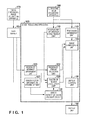
- Fig. 1 is a block diagram showing the device arrangement of an image processing apparatus according to the first embodiment
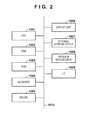
- Fig. 2 is a block diagram showing the basic arrangement of a computer which can implement each unit of the image processing apparatus by software according to the first embodiment
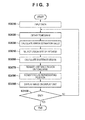
- Fig. 3 is a flowchart showing a processing sequence by the image processing apparatus according to the first embodiment
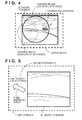
- Fig. 4 is a view for explaining a display method by the image processing apparatus according to the first embodiment
- Fig. 5 is a view for explaining the display method by the image processing apparatus according to the first embodiment
- Fig. 6 is a block diagram showing the device arrangement of an image processing apparatus according to the second embodiment
- Fig. 7 is a flowchart showing a processing sequence by the image processing apparatus according to the second embodiment.
- Fig. 8 is a view for explaining a display method by the image processing apparatus according to the second embodiment.
- an ultrasonic imaging system changes the display mode to non-display of information representing the three-dimensional position of a region of no interest on the current ultrasonic tomogram. Also, the ultrasonic imaging system changes the display mode of a figure representing the existence region of a corresponding region on the ultrasonic tomogram that corresponds to the unselected region of no interest, so that the region of no interest becomes less conspicuous than the region of interest (for example, the color is changed into a light one). This enables the operator to easily search for and identify a corresponding region on the ultrasonic tomogram (as a medical image).
- the region of interest is, for example, a lesion site.
- the region of interest is, for example, a lesion site to be diagnosed among a plurality of lesion sites.
- the region of interest is not limited to a lesion site, and suffices to be a region worth noting for a person who makes a diagnosis.
- the information representing a three-dimensional position the distance and direction are displayed in addition to a coordinate value.
- the embodiment will exemplify a case in which the breast of a human body serves as a target object.
- An ultrasonic imaging system according to the embodiment will be explained.
- the ultrasonic imaging system includes an image processing apparatus 100, an ultrasonic image diagnostic apparatus 180 capable of ultrasonic imaging using an ultrasonic probe, and a display unit 160.
- the ultrasonic imaging system is connected to a data server 190 which stores images from a three-dimensional image collecting apparatus 170.
- Fig. 1 shows the arrangement of the ultrasonic imaging system according to the embodiment.
- the image processing apparatus 100 in the embodiment performs navigation display for imaging a subject during ultrasonic imaging by an ultrasonic imaging apparatus, and the same apparatus performs the searching for the position of a lesion.
- the image processing apparatus 100 includes a tomogram obtainment unit 110, position and orientation measurement unit 112, region-of-interest obtainment unit 121, region-of-interest selection unit 122, error factor information obtainment unit 123, error estimation value calculation unit 124, existence region calculation unit 135, image composition unit 140, and display control unit 150.
- the image processing apparatus 100 is connected to the data server 190, and the ultrasonic image diagnostic apparatus 180 which captures the ultrasonic tomogram of a breast.
- the data server 190 holds information representing a plurality of lesion sites in three-dimensional image data.
- the three-dimensional image data is an image obtained by capturing a subject in advance by an MRI apparatus, X-ray CT apparatus, or the like serving as the three-dimensional image collecting apparatus 170.
- Information representing a lesion site is, for example, the position of the lesion site (barycentric position of the region), or the coordinates of a point group positioned at the boundary of the region of a lesion site of interest.
- information representing a lesion site is the position of a lesion site, and the position of the lesion site is expressed in the MRI apparatus coordinate system.
- the position of a lesion site held in the data server 190 is obtained by the region-of-interest obtainment unit 121 and input to the image processing apparatus 100.
- the data server 190 holds error factor information (details of which will be described later) for calculating the error estimation value of a corresponding lesion site.
- the error factor information is information for calculating the existence region of a corresponding lesion site on an ultrasonic tomogram.
- the error factor information held in the data server 190 is input to the image processing apparatus 100 via the error factor information obtainment unit 123.
- the ultrasonic image diagnostic apparatus 180 captures ultrasonic tomograms of a subject in real time. Ultrasonic tomograms are sequentially obtained by the tomogram obtainment unit 110 and sequentially input to the image processing apparatus 100. The position and orientation of the ultrasonic probe are measured by a position and orientation sensor (not shown), measured by the position and orientation measurement unit 112, and input to the image processing apparatus 100. The position and orientation of the ultrasonic probe are expressed by, for example, a position and orientation in a reference coordinate system using a subject as a reference. The position and orientation measurement unit 112 measures the position and orientation of the ultrasonic probe in the reference coordinate system, and based on them, calculates the position and orientation of an ultrasonic tomogram in the MRI apparatus coordinate system.
- the error estimation value calculation unit 124 calculates the error estimation value of a corresponding lesion site based on error factor information obtained by the error factor information obtainment unit 123.
- the error estimation value calculation unit 124 outputs the calculated error estimation value to the existence region calculation unit 135.
- the existence region calculation unit 135 estimates the position of a corresponding lesion site in an ultrasonic coordinate system that corresponds to each lesion site in three-dimensional image data.
- the ultrasonic coordinate system is a three-dimensional coordinate system using an ultrasonic tomogram as a reference.
- the ultrasonic coordinate system can be defined as, for example, a coordinate system in which one point on the tomogram is set as the origin, the x- and y-axes are set on the plane of the tomogram, and the z-axis is set in a direction perpendicular to the plane.
- the existence region calculation unit 135 specifies the position of each corresponding lesion site by calculating a region (existence region) where the corresponding lesion site may exist on the ultrasonic tomogram.
- the region-of-interest selection unit 122 selects a lesion site of interest from lesion sites obtained by the region-of-interest obtainment unit 121. Note that lesion sites other than the selected lesion site of interest serve as "lesion sites of no interest”.
- the image composition unit 140 obtains, from the existence region calculation unit 135, information representing the existence region of each corresponding lesion site, and superimposes and renders, on an ultrasonic tomogram obtained from the tomogram obtainment unit 110, a figure representing the existence region of each corresponding lesion site. If the existence region of a lesion site of interest does not exist on a slice, the image composition unit 140 calculates the three-dimensional position (distance and direction) of the lesion site of interest on the ultrasonic tomogram, and superimposes and renders, on the ultrasonic tomogram, information representing the calculated distance and direction.
- the display control unit 150 controls the display unit 160 to cause it to display an image obtained by the image composition unit 140. More specifically, the display control unit 150 controls the display unit 160 to cause it to display the positions of a plurality of regions of interest obtained by the region-of-interest obtainment unit 121, and display the existence region of a region of interest obtained by the existence region calculation unit 135 on an ultrasonic tomogram. By displaying the image obtained by the image composition unit 140, the display control unit 150 changes, by different methods in accordance with a selection, the display mode of the positions of regions of interest other than a selected region of interest, and that of existence regions corresponding to the regions of interest other than the selected region of interest.
- Fig. 1 may be implemented as independent apparatuses. Alternatively, they may be implemented as software programs which are installed in one or a plurality of computers and executed by the CPUs of the computers to implement the functions. In the embodiment, the various units are implemented by software programs which are installed in a single computer.
- Fig. 2 is a block diagram showing the basic arrangement of a computer which executes software programs to implement the functions of the various units (to be described later). These units are the tomogram obtainment unit 110, position and orientation measurement unit 112, region-of-interest obtainment unit 121, region-of-interest selection unit 122, error factor information obtainment unit 123, error estimation value calculation unit 124, existence region calculation unit 135, image composition unit 140, and display control unit 150.
- These units are the tomogram obtainment unit 110, position and orientation measurement unit 112, region-of-interest obtainment unit 121, region-of-interest selection unit 122, error factor information obtainment unit 123, error estimation value calculation unit 124, existence region calculation unit 135, image composition unit 140, and display control unit 150.
- a CPU 1001 controls the overall computer using programs and data which are stored in a RAM 1002 and ROM 1003.
- the CPU 1001 controls execution of programs corresponding to the tomogram obtainment unit 110, position and orientation measurement unit 112, region-of-interest obtainment unit 121, region-of-interest selection unit 122, error factor information obtainment unit 123, error estimation value calculation unit 124, existence region calculation unit 135, image composition unit 140, and display control unit 150.
- the RAM 1002 has an area for temporarily storing programs and data loaded from an external storage device 1007 and storage medium drive 1008. In addition, the RAM 1002 has a work area necessary to perform various processes by the CPU 1001.
- the ROM 1003 generally stores computer programs, setting data, and the like.
- a keyboard 1004 and mouse 1005 are input devices, and the operator can use them to input various instructions to the CPU 1001.
- a display unit 1006 is formed from a CRT, liquid crystal display, or the like, and corresponds to the display unit 160.
- the display unit 1006 can display a composite image generated by the image composition unit 140, a message and GUI to be displayed for image processing, and the like.
- the external storage device 1007 is a device functioning as a large-capacity information storage device such as a hard disk drive.
- An OS Operating System
- programs to be executed by the CPU 1001, and the like are saved in the external storage device 1007.
- information to be stored for subsequent use is saved in the external storage device 1007, and loaded into the RAM 1002, as needed.
- the storage medium drive 1008 reads out programs and data stored in a storage medium such as a CD-ROM or DVD-RAM in accordance with an instruction from the CPU 1001, and outputs them to the RAM 1002 or external storage device 1007.
- An I/F 1009 is formed from an analog video port, a digital I/O port such as an IEEE1394 port, an Ethernet® port for outputting outside information such as a composite image, and the like. Data input from the respective ports are loaded into the RAM 1002 via the I/F 1009.
- the I/F 1009 implements some of the functions of the tomogram obtainment unit 110, position and orientation measurement unit 112, region-of-interest obtainment unit 121, and error factor information obtainment unit 123. These building components are connected to each other by a bus 1010.
- Fig. 3 is a flowchart showing an overall processing sequence to be performed by the image processing apparatus 100.
- this flowchart is implemented when the CPU 1001 executes a program for implementing the function of each unit. It is assumed that program codes complying with this flowchart have already been loaded from, for example, the external storage device 1007 into the RAM 1002 before performing the following processing.
- step S3000 in the role of the region-of-interest obtainment unit 121, the image processing apparatus 100 obtains the position of a lesion site as the position of a region of interest from the data server 190.
- the image processing apparatus 100 obtains, from the data server 190, various kinds of error factor information used to calculate an error estimation value. For example, information representing the type of position and orientation sensor (for example, sensor A or sensor B) which measures the position and orientation of the ultrasonic probe is obtained as error factor information.
- step S3020 in the role of the tomogram obtainment unit 110, the image processing apparatus 100 obtains an ultrasonic tomogram from the ultrasonic image diagnostic apparatus 180.
- the image processing apparatus 100 obtains, from the ultrasonic image diagnostic apparatus 180, the position and orientation of the ultrasonic probe obtained when the ultrasonic tomogram was captured.
- the image processing apparatus 100 calculates the position and orientation of the ultrasonic tomogram in the MRI apparatus coordinate system from the position and orientation of the ultrasonic probe in the reference coordinate system.
- step S3030 in the role of the error estimation value calculation unit 124, the image processing apparatus 100 calculates an error estimation value based on various kinds of error factor information obtained in step S3000.
- the processing of calculating an error estimation value can be executed based on, for example, the characteristics of the position and orientation sensor which measures the position and orientation of the ultrasonic probe.
- the reference value of an error is set in advance for each type of position and orientation sensor so that a value can be selected in accordance with the type of sensor used. For example, when the error factor information input in step S3000 is information representing that sensor A serving as an optical sensor is used, an error estimation value can be calculated as a value smaller than that when sensor B serving as a magnetic sensor is used.
- the error estimation processing may be another processing.
- an error may arise from an alignment algorithm for a three-dimensional MRI image or three-dimensional CT image obtained by the three-dimensional image collecting apparatus 170, and an ultrasonic tomogram obtained by the ultrasonic image diagnostic apparatus 180.
- an error may arise from the deformation algorithm. Even for such an error arising from the deformation, an empirically obtained error magnitude is stored in advance in the memory and used for estimation of the magnitude of an error.
- step S3050 in the role of the region-of-interest selection unit 122, the image processing apparatus 100 selects, based on an instruction from the operator, at least one lesion site of interest from lesion sites obtained by the region-of-interest obtainment unit 121.
- respective lesion sites are numbered in advance so that the image processing apparatus 100 can obtain an instruction input by the operator by, for example, pressing a numeric key of the keyboard 1004 that corresponds to the number of a lesion site of interest.
- step S3060 in the role of the existence region calculation unit 135, the image processing apparatus 100 calculates the existence region of a corresponding lesion site corresponding to each of the lesion sites on the ultrasonic tomogram obtained in step S3020.
- the existence region calculation unit 135 estimates the position of a corresponding lesion site in the ultrasonic coordinate system that corresponds to the position of each lesion site obtained by the region-of-interest obtainment unit 121. This estimation can be performed based on the position and orientation of the ultrasonic tomogram that have been measured by the position and orientation measurement unit 112.
- the existence region calculation unit 135 calculates the existence region of each corresponding lesion site on the ultrasonic tomogram based on the estimated position of each corresponding lesion site, and the error estimation value calculated in step S3030.
- the three-dimensional existence region of the corresponding lesion site in the ultrasonic coordinate system is defined as a sphere having the estimated position of the corresponding lesion site as the center and the error estimation value as the radius.
- the existence region of the corresponding lesion site on the ultrasonic tomogram is defined as a circle which is a region (slice of the sphere) where the sphere and the tomogram cross each other.
- the existence region calculation unit 135 calculates the center position and radius of the circle on the ultrasonic tomogram. Note that the method of calculating the cross region of a sphere and plane that are defined in a three-dimensional space is well known, and a description thereof will be omitted. If the sphere regarding the lesion site of interest selected by the region-of-interest selection unit 122, and the tomogram do not cross each other, information "the existence region of the lesion site of interest does not exist on the slice" is saved.
- step S3070 as processing of the image composition unit 140, the image processing apparatus 100 generates an image in which a figure representing the existence region of each corresponding lesion site that has been calculated in step S3060 is superimposed and rendered on the ultrasonic tomogram.
- the range where the corresponding lesion site may exist is rendered by a line of a closed curve.
- a figure representing the existence region of a lesion site of no interest i.e. a region containing a lesion, but that is not of current interest
- the region-of-interest selection unit 122 is rendered in a display mode in which the figure becomes less conspicuous than a figure representing the existence region of the lesion site of interest.
- Fig. 4 exemplifies an image generated by the processing of this step. If no lesion site of interest has been selected in step S3050, figures representing the existence regions of respective lesion sites are rendered in the same display mode without discrimination.
- step S3060 If it is determined in step S3060 that "the existence region of the lesion site of interest does not exist on the slice", the processing of this step may not be executed.
- the existence region of a lesion site of no interest which means a site containing a lesion but that is not of current interest, is rendered only when the existence region of the lesion site of interest exists on the slice.
- step S3090 in the role of the image composition unit 140, if it is determined that "the existence region of the lesion site of interest does not exist on the slice", the image processing apparatus 100 renders a figure representing the position of the lesion site of interest. More specifically, the three-dimensional position (distance and direction) of the lesion site of interest on the ultrasonic tomogram is calculated. Then, an image is generated in which information representing the calculated distance and direction is superimposed on the image processed in step S3070.
- Fig. 5 exemplifies an image generated by the processing of this step. If no lesion site of interest has been selected in step S3050, figures representing the positions of respective lesion sites are rendered in the same display mode without discrimination.
- the example in FIG. 5 shows the ultrasonic tomogram with no lesion (no region of interest) and a three-dimensional arrow with a label giving distance information to the lesion site of interest, such as "xmm to lesion site of interest".
- step S3095 in the role of the display control unit 150, the image processing apparatus 100 displays the image composited in step S3090 on the display unit 160. If necessary, the image processing apparatus 100 outputs the composite image to the outside via the I/F 1009. Further, the image processing apparatus 100 stores the image in the RAM 1002 so that it can be used from another application.
- step S3100 the image processing apparatus 100 determines whether to end the overall processing. For example, the image processing apparatus 100 obtains an end instruction based on, for example, pressing of a predetermined key (end key) of the keyboard 1004 by the operator. If the image processing apparatus 100 determines that it is to end the overall processing, it ends the overall processing of the image processing apparatus 100. If the image processing apparatus 100 determines that it is not to end the overall processing, it returns the process to step S3020, and executes again the processes in step S3020 and subsequent steps for a newly captured ultrasonic tomogram. In this manner, the processing of the image processing apparatus 100 is executed.
- end key end key
- the image processing apparatus can change, to non-display, the display mode of information representing the three-dimensional position (distance and direction) of a lesion site of no interest on an ultrasonic tomogram. Also, the image processing apparatus can change the display mode of a figure representing the existence region of a lesion site of no interest on the ultrasonic tomogram so that the lesion site of no interest becomes less conspicuous than a lesion site of interest. Since information representing the three-dimensional position (distance and direction) of the lesion site of no interest on the ultrasonic tomogram is not displayed, it does not hinder search for a corresponding lesion site corresponding to the lesion site of interest.
- the operator can grasp whether a lesion site which may cause an identification error exists near the lesion site of interest. That is, the image processing apparatus according to the first embodiment can efficiently search a target image for a corresponding lesion site corresponding to a lesion site of interest selected from a plurality of lesion sites in a reference image, and identify the lesion site of interest.
- a lesion site of interest is selected based on an instruction from the operator.
- a lesion site of interest may be selected in advance and held in the data server 190.
- the region-of-interest selection unit 122 in Fig. 1 may be omitted, and the region-of-interest selection processing in step S3050 need not be performed.
- the above-described embodiment has exemplified a case in which the color of a figure representing the existence region of a lesion site of no interest is changed into a light color.
- the display mode change method is not limited to this.
- the thickness or type of the line of the figure may be changed, or the saturation of the color of the figure may be decreased.
- An ultrasonic imaging system changes, to non-display, the display mode of a figure representing a region (existence region) where a corresponding lesion site on an ultrasonic tomogram that corresponds to a lesion site (lesion site of no interest) other than a lesion site of interest may exist.
- the ultrasonic imaging system changes the display mode of a figure representing the position of a lesion site of no interest on a body mark image (i.e. a schematic image of a part of the body or a schema) representing a target object, so that the lesion site of no interest becomes less conspicuous than the lesion site of interest (for example, the color is changed into a light one). This enables the operator to easily search for and identify a corresponding lesion site on the ultrasonic tomogram.
- a difference of the ultrasonic imaging system according to the second embodiment from the first embodiment will be mainly explained.
- Fig. 6 shows the arrangement of the ultrasonic imaging system according to the second embodiment. Note that the same reference numerals and symbols as those in Fig. 1 denote the same parts, and a description thereof will not be repeated.
- Three-dimensional image data held in a data server 190 is obtained by a three-dimensional image data obtainment unit 620 and input to an image processing apparatus 600.
- three-dimensional image data is expressed as three-dimensional volume data in which a luminance value is stored in a three-dimensional voxel.
- the coordinates of each voxel are expressed in the MRI apparatus coordinate system.
- An ultrasonic image diagnostic apparatus 680 holds a body mark image.
- This body mark is an image representing the schematic shape of a breast, and is an image for schematically showing the position of a lesion.
- a body mark for the left breast and a body mark for the right breast which are held in the ultrasonic image diagnostic apparatus 680 are obtained by a body mark obtainment unit 614 and input to the image processing apparatus 600.
- a conversion region calculation unit 616 converts the position of each lesion site obtained by a region-of-interest obtainment unit 121 into a position in a body mark coordinate system.
- the body mark coordinate system is a system in which a plane containing the body mark for the left breast and that for the right breast is defined as the x-y plane, and an axis perpendicular to the x-y plane is defined as the z-axis.
- a slice image generation unit 630 receives three-dimensional volume data output from the three-dimensional image data obtainment unit 620, and the position and orientation of an ultrasonic tomogram output from a position and orientation measurement unit 112. Based on these data, the slice image generation unit 630 generates a slice image corresponding to the ultrasonic tomogram from the three-dimensional volume data, and outputs it to an image composition unit 640.
- the image composition unit 640 obtains, from an existence region calculation unit 135, information representing the existence region of a corresponding lesion site.
- the image composition unit 640 superimposes and renders, on an ultrasonic tomogram obtained from a tomogram obtainment unit 110, information representing the existence region of a corresponding lesion site corresponding to a lesion site of interest selected by a region-of-interest selection unit 122.
- the image composition unit 640 obtains the position of each lesion site from the conversion region calculation unit 616, and renders a figure representing the position of each lesion site on a body mark obtained from the body mark obtainment unit. Further, the image composition unit 640 generates a composite image by compositing these images and the slice image obtained from the slice image generation unit 630.
- the image composition unit 640 outputs the composite image to a display control unit 150 or to outside.
- the display control unit 150 obtains the composite image output from the image composition unit 640, and displays it on a display unit 160.
- Fig. 7 is a flowchart showing an overall processing sequence to be performed by the image processing apparatus 600.
- this flowchart is implemented when a CPU 1001 executes a program for implementing the function of each unit. Assume that program codes complying with this flowchart have already been loaded from, for example, an external storage device 1007 into a RAM 1002 before performing the following processing.
- step S7000 in the role of the three-dimensional image data obtainment unit 620, the image processing apparatus 600 obtains three-dimensional image data from the data server 190, in addition to the processing in step S3000.
- the image processing apparatus 600 obtains a body mark for the left breast and a body mark for the right breast from the ultrasonic image diagnostic apparatus 680.
- step S7010 in the role of the conversion region calculation unit 616, the image processing apparatus 600 converts the position of each lesion site obtained by the region-of-interest obtainment unit 121 into a position in the body mark coordinate system.
- This conversion is disclosed in, for example, Japanese Patent Laid-Open No. 2008-086742 . More specifically, coordinate conversion from a position on a breast into a position on a standard body mark representing a breast is executed.
- steps S7020 and S7030 are the same as those in steps S3020 and S3030 in the first embodiment, and a description thereof will be omitted.
- step S7040 in the role of the slice image generation unit 630, the image processing apparatus 600 generates the slice image of a reference image corresponding to an ultrasonic tomogram obtained in step S7020. More specifically, based on the position and orientation of the ultrasonic tomogram obtained in step S7020, the image processing apparatus 600 generates a slice image by extracting the same slice as the ultrasonic tomogram from the three-dimensional volume data obtained in step S7000.
- step S7050 in the role of the region-of-interest selection unit 122, the image processing apparatus 600 selects, based on an instruction from the operator, a lesion site of interest from lesion sites obtained by the region-of-interest obtainment unit 121. For example, by clicking a mouse 1005, the operator can select a figure representing the position of a lesion site of interest on the body mark.
- step S7060 Processing in step S7060 is the same as that in step S3060 in the first embodiment, and a description thereof will not be repeated.
- step S7070 the image composition unit 640 of the image processing apparatus 600 generates an image in which a figure representing the existence region of a corresponding lesion site corresponding to the lesion site of interest selected in step S7050 is superimposed and rendered on the ultrasonic tomogram.
- a figure representing the existence region of a corresponding lesion site corresponding to the lesion site of interest selected in step S7050 is superimposed and rendered on the ultrasonic tomogram.
- the range where the corresponding lesion site may exist is rendered by a closed curve. If no lesion site of interest has been selected in step S7050, figures representing the existence regions of respective lesion sites are rendered in the same display mode without discrimination.
- step S7080 in the role of the image composition unit 640, first, the image processing apparatus 600 selects either the body mark for the left breast or that for the right breast to be used. For example, when a lesion site of interest has been selected in step S7050, it is determined which of the left and right breasts contains the selected lesion site of interest, and then a body mark for use can be selected. More specifically, the distances between the position of the lesion site of interest in the body mark coordinate system that has been calculated in step S7010, and the positions of the left and right nipples in the body mark coordinate system are calculated, and a body mark having a shorter distance can be selected. Alternatively, at which of the positions of the left and right breasts the ultrasonic probe exists is determined based on the position and orientation of the ultrasonic tomogram measured by the position and orientation measurement unit 112, and a body mark for use can be selected.
- a figure representing the position of a lesion site is rendered at the position of each lesion site on the selected body mark.
- a figure representing the position of a lesion site of no interest other than the lesion site of interest selected by the region-of-interest selection unit 122 is rendered in a display mode in which the figure becomes less conspicuous than a figure representing the position of the lesion site of interest. For example, the color of the figure is changed into a light color. If no lesion site of interest has been selected in step S7050, figures representing the positions of respective lesion sites are rendered in the same display mode without discrimination.
- the position of the probe in the body mark coordinate system is calculated based on the position and orientation of the ultrasonic tomogram measured by the position and orientation measurement unit 112, and a figure (probe mark) representing the position of the probe is rendered on the body mark.
- step S7095 the image composition unit 640 generates a slice image, an image in which the existence region of the lesion site of interest is superimposed on the ultrasonic tomogram, and an image in which the lesion position is rendered on the body mark image. Then, for example, the image composition unit 640 aligns these images, generating a composite image as shown in Fig. 8.
- FIG. 8 shows a composite image made up of three images. The top left image is a slice image of a reference image containing a two-dimensional slice of a 3-D volume of a breast and cross-sections of ribs. The slice corresponds in the 3-D image data to the position of an ultrasonic tomogram.
- the top right image shows the corresponding ultrasonic tomogram containing the corresponding lesion site as a shaded shape and an existence region shown as a circle.
- the bottom image shows a body mark with a left-hand cross representing a position of the lesion site of no interest and a right-hand, darker cross as a figure representing a position of the lesion site of interest. There is also illustrated a mark representing the ultrasonic probe position.
- the image composition unit 640 displays the composite image on the display unit 160.
- the display control unit 150 deletes, from the ultrasonic image, the display of an existence region corresponding to a region of interest serving as the region of interest before the change.
- the deletion includes displaying an image in which no existence region is superimposed on an ultrasonic image in accordance with change of the region of interest.
- the display control unit 150 controls the display unit 160 to display the positions of respective regions of interest on a body mark (first image), and display an existence region representing the existence range of a selected region of interest on an ultrasonic image (second image) in accordance with a selection by the region-of-interest selection unit 122.
- the display control unit 150 switches the display from the existence region of a region of interest before the change to the existence region of a region of interest after the change.
- the display control unit 150 controls a display so as not to display, on the ultrasonic image (second image), the existence region of an unselected region of interest among a plurality of obtained regions of interest.
- the display control unit 150 displays the position of the selected region of interest by using the first figure on the body mark (first image), and display the position of the unselected region of interest by using the second figure different from the first figure.
- the display control unit 150 displays the position of the ultrasonic probe on the body mark (first image).
- the composite image is output outside via an I/F 1009, and stored in the RAM 1002 so that it can be used from another application.
- step S7100 Processing in step S7100 is the same as that in step S3100 in the first embodiment, and a description thereof will not be repeated.
- the image processing apparatus can change the display mode of a figure representing the position of a lesion site of no interest on a body mark so that the figure becomes less conspicuous than a figure representing the position of a lesion site of interest.
- the image processing apparatus can change, to non-display, the display mode of a figure representing the existence region of a lesion site of no interest on an ultrasonic tomogram. By observing the body mark, the operator can grasp whether a lesion site which may cause an identification error exists near the lesion site of interest.
- the image processing apparatus can efficiently search a target image for a corresponding lesion site corresponding to a lesion site of interest selected from a plurality of lesion sites in a reference image, and identify the lesion site of interest.
- the slice image need not always be displayed. In this case, neither obtainment of three-dimensional image data serving as a reference image nor slice image generation processing may be executed.
- the above-described embodiment has exemplified a case in which the color of a figure representing the position of a lesion site of no interest in a body mark representing a target object is changed into a light color.
- the display mode change method is not limited to this.
- the thickness or type of the line of the figure may be changed, or the saturation of the color of the figure may be decreased.
- the display control unit 150 When, for example, the position of a lesion site of no interest is spaced apart from a lesion site of interest by a predetermined distance, and the lesion site of interest is less likely to be erroneously identified as a lesion site of no interest, the display control unit 150 does not display a figure representing the position of the lesion site of no interest in the body mark representing the target object. That is, the display control unit 150 restricts display of the position of a region of interest on the first image based on the positional relationship between the existence region of a selected region of interest and the position of an unselected region of interest. This can make the display more recognizable.
- aspects of the present invention can also be realized by a computer of a system or apparatus (or devices such as a CPU or MPU) that reads out and executes a program recorded on a memory device to perform the functions of the above-described embodiment(s), and by a method, the steps of which are performed by a computer of a system or apparatus by, for example, reading out and executing a program recorded on a memory device to perform the functions of the above-described embodiment(s).
- the program is provided to the computer for example via a network or from a recording medium of various types serving as the memory device (for example, computer-readable medium).
Landscapes
- Health & Medical Sciences (AREA)
- Life Sciences & Earth Sciences (AREA)
- Engineering & Computer Science (AREA)
- Physics & Mathematics (AREA)
- Heart & Thoracic Surgery (AREA)
- Surgery (AREA)
- Pathology (AREA)
- Radiology & Medical Imaging (AREA)
- Biophysics (AREA)
- Biomedical Technology (AREA)
- Veterinary Medicine (AREA)
- Medical Informatics (AREA)
- Molecular Biology (AREA)
- Nuclear Medicine, Radiotherapy & Molecular Imaging (AREA)
- Animal Behavior & Ethology (AREA)
- General Health & Medical Sciences (AREA)
- Public Health (AREA)
- Computer Vision & Pattern Recognition (AREA)
- General Physics & Mathematics (AREA)
- Theoretical Computer Science (AREA)
- Vascular Medicine (AREA)
- Human Computer Interaction (AREA)
- Ultra Sonic Daignosis Equipment (AREA)
Applications Claiming Priority (1)
| Application Number | Priority Date | Filing Date | Title |
|---|---|---|---|
| JP2012015934A JP6039903B2 (ja) | 2012-01-27 | 2012-01-27 | 画像処理装置、及びその作動方法 |
Publications (1)
| Publication Number | Publication Date |
|---|---|
| EP2620911A1 true EP2620911A1 (de) | 2013-07-31 |
Family
ID=47681702
Family Applications (1)
| Application Number | Title | Priority Date | Filing Date |
|---|---|---|---|
| EP13152765.7A Withdrawn EP2620911A1 (de) | 2012-01-27 | 2013-01-25 | Bildverarbeitungsvorrichtung, Bildverarbeitungssystem und Bildverarbeitungsverfahren |
Country Status (3)
| Country | Link |
|---|---|
| US (2) | US20130195339A1 (de) |
| EP (1) | EP2620911A1 (de) |
| JP (1) | JP6039903B2 (de) |
Cited By (4)
| Publication number | Priority date | Publication date | Assignee | Title |
|---|---|---|---|---|
| EP3001339A1 (de) * | 2014-09-26 | 2016-03-30 | Samsung Electronics Co., Ltd. | Vorrichtung und verfahren zur unterstützung computergestützter diagnose |
| CN108720934A (zh) * | 2017-04-20 | 2018-11-02 | 卡尔蔡司医疗技术股份公司 | 用于操作医学-光学显示系统的方法 |
| CN109310400A (zh) * | 2016-06-07 | 2019-02-05 | 皇家飞利浦有限公司 | 用于乳房组织成像和注释乳房超声图像的超声系统和方法 |
| CN109598752A (zh) * | 2017-10-03 | 2019-04-09 | 佳能株式会社 | 图像处理装置及其控制方法、计算机可读存储介质 |
Families Citing this family (15)
| Publication number | Priority date | Publication date | Assignee | Title |
|---|---|---|---|---|
| JP5685133B2 (ja) | 2011-04-13 | 2015-03-18 | キヤノン株式会社 | 画像処理装置、画像処理装置の制御方法、およびプログラム |
| JP5995449B2 (ja) | 2012-01-24 | 2016-09-21 | キヤノン株式会社 | 情報処理装置及びその制御方法 |
| CA2895975A1 (en) * | 2012-12-21 | 2014-06-26 | Volcano Corporation | Display control for a multi-sensor medical device |
| RU2689176C2 (ru) * | 2014-01-02 | 2019-05-24 | Конинклейке Филипс Н.В. | Ориентация и отслеживание положения инструмента относительно плоскости ультразвукового изображения |
| US9808213B2 (en) * | 2014-08-11 | 2017-11-07 | Canon Kabushiki Kaisha | Image processing apparatus, image processing method, medical image diagnostic system, and storage medium |
| KR20160032586A (ko) * | 2014-09-16 | 2016-03-24 | 삼성전자주식회사 | 관심영역 크기 전이 모델 기반의 컴퓨터 보조 진단 장치 및 방법 |
| JP6532206B2 (ja) | 2014-10-01 | 2019-06-19 | キヤノン株式会社 | 医用画像処理装置、医用画像処理方法 |
| JP7432296B2 (ja) * | 2016-09-12 | 2024-02-16 | キヤノンメディカルシステムズ株式会社 | 医用情報処理システム |
| JP7237829B2 (ja) | 2016-11-11 | 2023-03-13 | ガイネソニックス, インコーポレイテッド | 組織の制御された治療と組織および/または治療データとの動的相互作用およびそれらの比較 |
| JP6982978B2 (ja) | 2017-04-26 | 2021-12-17 | キヤノン株式会社 | 情報処理装置、情報処理方法、およびプログラム |
| JP6796725B2 (ja) * | 2017-09-26 | 2020-12-09 | 富士フイルム株式会社 | 医療画像処理システム、内視鏡システム、診断支援装置、及び医療業務支援装置 |
| US11328485B2 (en) * | 2019-08-23 | 2022-05-10 | Tencent America LLC | Method and apparatus for displaying an augmented-reality image corresponding to a microscope view |
| JP2021052321A (ja) * | 2019-09-25 | 2021-04-01 | ソニー株式会社 | 画像処理装置、画像処理方法、プログラム、および画像処理システム |
| KR102536369B1 (ko) * | 2021-02-26 | 2023-05-26 | 주식회사 인피니트헬스케어 | 인공 지능 기반 위 내시경 영상 진단 보조 시스템 및 방법 |
| KR102531400B1 (ko) * | 2021-03-19 | 2023-05-12 | 주식회사 인피니트헬스케어 | 인공 지능 기반 대장 내시경 영상 진단 보조 시스템 및 방법 |
Citations (3)
| Publication number | Priority date | Publication date | Assignee | Title |
|---|---|---|---|---|
| US20090129650A1 (en) * | 2007-11-19 | 2009-05-21 | Carestream Health, Inc. | System for presenting projection image information |
| WO2011074162A1 (en) * | 2009-12-18 | 2011-06-23 | Canon Kabushiki Kaisha | Image processing apparatus, image processing method, image processing system, and program |
| US20110178389A1 (en) * | 2008-05-02 | 2011-07-21 | Eigen, Inc. | Fused image moldalities guidance |
Family Cites Families (33)
| Publication number | Priority date | Publication date | Assignee | Title |
|---|---|---|---|---|
| JP4443672B2 (ja) * | 1998-10-14 | 2010-03-31 | 株式会社東芝 | 超音波診断装置 |
| US6980690B1 (en) * | 2000-01-20 | 2005-12-27 | Canon Kabushiki Kaisha | Image processing apparatus |
| WO2004098414A1 (ja) | 2003-05-08 | 2004-11-18 | Hitachi Medical Corporation | 超音波診断におけるリファレンス像表示方法及び超音波診断装置 |
| US7894646B2 (en) * | 2003-08-01 | 2011-02-22 | Hitachi Medical Corporation | Medical image diagnosis support device and method for calculating degree of deformation from normal shapes of organ regions |
| EP1523939B1 (de) * | 2003-10-14 | 2012-03-07 | Olympus Corporation | Ultraschalldiagnosegerät |
| US7787013B2 (en) * | 2004-02-03 | 2010-08-31 | Panasonic Corporation | Monitor system and camera |
| JP5036534B2 (ja) * | 2004-04-26 | 2012-09-26 | ヤンケレヴィッツ,デヴィット,エフ. | 標的病変における変化の精密な測定評価のための医療用撮像システム |
| JP4470187B2 (ja) | 2004-12-03 | 2010-06-02 | 株式会社日立メディコ | 超音波装置、超音波撮像プログラム及び超音波撮像方法 |
| JP2007029456A (ja) * | 2005-07-27 | 2007-02-08 | Matsushita Electric Ind Co Ltd | 超音波診断装置 |
| US20070167784A1 (en) * | 2005-12-13 | 2007-07-19 | Raj Shekhar | Real-time Elastic Registration to Determine Temporal Evolution of Internal Tissues for Image-Guided Interventions |
| JP5738507B2 (ja) | 2006-01-19 | 2015-06-24 | 東芝メディカルシステムズ株式会社 | 超音波プローブの軌跡表現装置及び超音波診断装置 |
| JP5121204B2 (ja) * | 2006-10-11 | 2013-01-16 | オリンパス株式会社 | 画像処理装置、画像処理方法、および画像処理プログラム |
| US8134554B1 (en) * | 2007-05-04 | 2012-03-13 | Topcon Medical Systems, Inc. | Method and apparatus for spatially mapping three-dimensional optical coherence tomography data with two-dimensional images |
| JP2009112436A (ja) * | 2007-11-05 | 2009-05-28 | Toshiba Corp | 超音波診断装置 |
| JP4468432B2 (ja) | 2007-11-30 | 2010-05-26 | 株式会社東芝 | 超音波診断装置 |
| CN101677799B (zh) * | 2008-03-25 | 2012-05-30 | 株式会社东芝 | 医用图像处理装置以及x射线诊断装置 |
| EP2120208A1 (de) * | 2008-05-13 | 2009-11-18 | IBBT vzw | Verfahren und System zur Läsionssegmentierung |
| JP5335280B2 (ja) * | 2008-05-13 | 2013-11-06 | キヤノン株式会社 | 位置合わせ処理装置、位置合わせ方法、プログラム、及び記憶媒体 |
| JP5395371B2 (ja) * | 2008-06-18 | 2014-01-22 | 株式会社東芝 | 超音波診断装置、超音波画像の取得方法及びプログラム |
| WO2010017356A2 (en) * | 2008-08-08 | 2010-02-11 | University Of Pittsburgh - Of The Commonwealth System Of Higher Education | Establishing compatibility between two-and three dimensional optical coherence tomography scans |
| JP2010194007A (ja) * | 2009-02-24 | 2010-09-09 | Toshiba Corp | 超音波撮影装置、画像処理装置及び画像処理プログラム |
| JP5400466B2 (ja) * | 2009-05-01 | 2014-01-29 | キヤノン株式会社 | 画像診断装置、画像診断方法 |
| JP5417047B2 (ja) * | 2009-06-02 | 2014-02-12 | 株式会社東芝 | 超音波診断装置 |
| JP2011136044A (ja) * | 2009-12-28 | 2011-07-14 | Panasonic Corp | 超音波診断装置 |
| JP5597021B2 (ja) * | 2010-04-15 | 2014-10-01 | オリンパス株式会社 | 画像処理装置及びプログラム |
| JP5737858B2 (ja) | 2010-04-21 | 2015-06-17 | キヤノン株式会社 | 画像処理装置、画像処理方法、及びプログラム |
| JP5728212B2 (ja) | 2010-11-30 | 2015-06-03 | キヤノン株式会社 | 診断支援装置、診断支援装置の制御方法、およびプログラム |
| US9615064B2 (en) * | 2010-12-30 | 2017-04-04 | Pelco, Inc. | Tracking moving objects using a camera network |
| JP5858636B2 (ja) | 2011-04-13 | 2016-02-10 | キヤノン株式会社 | 画像処理装置、その処理方法及びプログラム |
| JP5965596B2 (ja) * | 2011-07-27 | 2016-08-10 | オリンパス株式会社 | 画像処理システム、情報処理装置及びプログラム |
| US10049445B2 (en) | 2011-07-29 | 2018-08-14 | Canon Kabushiki Kaisha | Image processing apparatus and image processing method of a three-dimensional medical image |
| JP5995449B2 (ja) | 2012-01-24 | 2016-09-21 | キヤノン株式会社 | 情報処理装置及びその制御方法 |
| US8977026B2 (en) * | 2012-05-30 | 2015-03-10 | General Electric Company | Methods and systems for locating a region of interest in an object |
-
2012
- 2012-01-27 JP JP2012015934A patent/JP6039903B2/ja active Active
-
2013
- 2013-01-18 US US13/744,619 patent/US20130195339A1/en not_active Abandoned
- 2013-01-25 EP EP13152765.7A patent/EP2620911A1/de not_active Withdrawn
-
2016
- 2016-10-13 US US15/292,462 patent/US10417517B2/en active Active
Patent Citations (3)
| Publication number | Priority date | Publication date | Assignee | Title |
|---|---|---|---|---|
| US20090129650A1 (en) * | 2007-11-19 | 2009-05-21 | Carestream Health, Inc. | System for presenting projection image information |
| US20110178389A1 (en) * | 2008-05-02 | 2011-07-21 | Eigen, Inc. | Fused image moldalities guidance |
| WO2011074162A1 (en) * | 2009-12-18 | 2011-06-23 | Canon Kabushiki Kaisha | Image processing apparatus, image processing method, image processing system, and program |
Cited By (8)
| Publication number | Priority date | Publication date | Assignee | Title |
|---|---|---|---|---|
| EP3001339A1 (de) * | 2014-09-26 | 2016-03-30 | Samsung Electronics Co., Ltd. | Vorrichtung und verfahren zur unterstützung computergestützter diagnose |
| CN105468891A (zh) * | 2014-09-26 | 2016-04-06 | 三星电子株式会社 | 用于支持计算机辅助诊断的设备和方法 |
| US9990710B2 (en) | 2014-09-26 | 2018-06-05 | Samsung Electronics Co., Ltd. | Apparatus and method for supporting computer aided diagnosis |
| CN109310400A (zh) * | 2016-06-07 | 2019-02-05 | 皇家飞利浦有限公司 | 用于乳房组织成像和注释乳房超声图像的超声系统和方法 |
| CN109310400B (zh) * | 2016-06-07 | 2021-06-29 | 皇家飞利浦有限公司 | 用于乳房组织成像和注释乳房超声图像的超声系统和方法 |
| CN108720934A (zh) * | 2017-04-20 | 2018-11-02 | 卡尔蔡司医疗技术股份公司 | 用于操作医学-光学显示系统的方法 |
| CN109598752A (zh) * | 2017-10-03 | 2019-04-09 | 佳能株式会社 | 图像处理装置及其控制方法、计算机可读存储介质 |
| CN109598752B (zh) * | 2017-10-03 | 2023-05-26 | 佳能株式会社 | 图像处理装置及其控制方法、计算机可读存储介质 |
Also Published As
| Publication number | Publication date |
|---|---|
| JP2013153883A (ja) | 2013-08-15 |
| JP6039903B2 (ja) | 2016-12-07 |
| US10417517B2 (en) | 2019-09-17 |
| US20130195339A1 (en) | 2013-08-01 |
| US20170032533A1 (en) | 2017-02-02 |
Similar Documents
| Publication | Publication Date | Title |
|---|---|---|
| US10417517B2 (en) | Medical image correlation apparatus, method and storage medium | |
| US10537247B2 (en) | Information processing apparatus, method, and programmed storage medium, for calculating ranges of regions of interest of scanned or other images | |
| EP2823765B1 (de) | Vorrichtung zur anzeige medizinischer bilder, verfahren zur anzeige medizinischer bilder und programm zur anzeige medizinischer bilder | |
| US9129362B2 (en) | Semantic navigation and lesion mapping from digital breast tomosynthesis | |
| WO2011074207A1 (en) | Image registration | |
| US8907952B2 (en) | Reparametrized bull's eye plots | |
| JP5430203B2 (ja) | 画像処理装置、画像処理方法 | |
| US9123096B2 (en) | Information processing apparatus and control method thereof | |
| JP5345934B2 (ja) | 観察のための三次元レンダリングからのデータ集合の選択 | |
| JP5631453B2 (ja) | 画像処理装置、画像処理方法 | |
| JP2009522005A (ja) | 時間横断的かつモダリティ横断的な医療診断 | |
| CN104933698A (zh) | 图像处理装置以及图像处理方法 | |
| JP2009000153A (ja) | 画像診断支援装置、方法及びプログラム | |
| EP3061066B1 (de) | Verfahren zur unterstützung von tumorreaktionsmessungen | |
| EP2272427A1 (de) | Bildverarbeitungsvorrichtung und verfahren sowie programm | |
| JP6487999B2 (ja) | 情報処理装置、情報処理方法、及びプログラム | |
| JP6263248B2 (ja) | 情報処理装置、情報処理方法、及びプログラム | |
| JP6400160B2 (ja) | 情報処理装置 | |
| JP5991731B2 (ja) | 情報処理装置及び情報処理方法 | |
| JP6391544B2 (ja) | 医用画像処理装置、医用画像処理方法、及びプログラム | |
| JP6719898B2 (ja) | 画像観察装置 |
Legal Events
| Date | Code | Title | Description |
|---|---|---|---|
| PUAI | Public reference made under article 153(3) epc to a published international application that has entered the european phase |
Free format text: ORIGINAL CODE: 0009012 |
|
| AK | Designated contracting states |
Kind code of ref document: A1 Designated state(s): AL AT BE BG CH CY CZ DE DK EE ES FI FR GB GR HR HU IE IS IT LI LT LU LV MC MK MT NL NO PL PT RO RS SE SI SK SM TR |
|
| AX | Request for extension of the european patent |
Extension state: BA ME |
|
| 17P | Request for examination filed |
Effective date: 20140131 |
|
| RBV | Designated contracting states (corrected) |
Designated state(s): AL AT BE BG CH CY CZ DE DK EE ES FI FR GB GR HR HU IE IS IT LI LT LU LV MC MK MT NL NO PL PT RO RS SE SI SK SM TR |
|
| STAA | Information on the status of an ep patent application or granted ep patent |
Free format text: STATUS: THE APPLICATION HAS BEEN WITHDRAWN |
|
| 18W | Application withdrawn |
Effective date: 20161108 |