EP2620302B1 - Palier à amortissement hydraulique pour un châssis de véhicule, en particulier d'un véhicule automobile, ainsi que procédé de modification de la position d'un palier de châssis - Google Patents
Palier à amortissement hydraulique pour un châssis de véhicule, en particulier d'un véhicule automobile, ainsi que procédé de modification de la position d'un palier de châssis Download PDFInfo
- Publication number
- EP2620302B1 EP2620302B1 EP12198216.9A EP12198216A EP2620302B1 EP 2620302 B1 EP2620302 B1 EP 2620302B1 EP 12198216 A EP12198216 A EP 12198216A EP 2620302 B1 EP2620302 B1 EP 2620302B1
- Authority
- EP
- European Patent Office
- Prior art keywords
- bearing
- flow
- chamber
- chambers
- shut
- Prior art date
- Legal status (The legal status is an assumption and is not a legal conclusion. Google has not performed a legal analysis and makes no representation as to the accuracy of the status listed.)
- Active
Links
- 238000000034 method Methods 0.000 title claims description 9
- 239000000725 suspension Substances 0.000 title claims description 5
- 239000007788 liquid Substances 0.000 claims description 38
- 238000013016 damping Methods 0.000 claims description 28
- 229920001971 elastomer Polymers 0.000 claims description 21
- 239000000806 elastomer Substances 0.000 claims description 21
- 230000001105 regulatory effect Effects 0.000 claims description 8
- 230000006835 compression Effects 0.000 claims description 4
- 238000007906 compression Methods 0.000 claims description 4
- 239000012528 membrane Substances 0.000 claims description 4
- 239000012530 fluid Substances 0.000 description 8
- 230000008859 change Effects 0.000 description 7
- 238000006073 displacement reaction Methods 0.000 description 7
- 230000008569 process Effects 0.000 description 3
- 230000000903 blocking effect Effects 0.000 description 2
- 238000005516 engineering process Methods 0.000 description 2
- 238000002955 isolation Methods 0.000 description 2
- 235000015095 lager Nutrition 0.000 description 2
- 230000003534 oscillatory effect Effects 0.000 description 2
- 238000010521 absorption reaction Methods 0.000 description 1
- 230000000712 assembly Effects 0.000 description 1
- 238000000429 assembly Methods 0.000 description 1
- 230000033228 biological regulation Effects 0.000 description 1
- 230000005540 biological transmission Effects 0.000 description 1
- 238000010276 construction Methods 0.000 description 1
- 230000001419 dependent effect Effects 0.000 description 1
- 238000010586 diagram Methods 0.000 description 1
- 230000005489 elastic deformation Effects 0.000 description 1
- 239000013536 elastomeric material Substances 0.000 description 1
- 238000009472 formulation Methods 0.000 description 1
- 230000002452 interceptive effect Effects 0.000 description 1
- 238000004519 manufacturing process Methods 0.000 description 1
- 230000007246 mechanism Effects 0.000 description 1
- 239000000203 mixture Substances 0.000 description 1
- 230000004044 response Effects 0.000 description 1
- 238000000926 separation method Methods 0.000 description 1
- 230000003068 static effect Effects 0.000 description 1
- 230000001629 suppression Effects 0.000 description 1
Images

Classifications
-
- B—PERFORMING OPERATIONS; TRANSPORTING
- B60—VEHICLES IN GENERAL
- B60G—VEHICLE SUSPENSION ARRANGEMENTS
- B60G7/00—Pivoted suspension arms; Accessories thereof
- B60G7/006—Attaching arms to sprung or unsprung part of vehicle, characterised by comprising attachment means controlled by an external actuator, e.g. a fluid or electrical motor
-
- B—PERFORMING OPERATIONS; TRANSPORTING
- B60—VEHICLES IN GENERAL
- B60G—VEHICLE SUSPENSION ARRANGEMENTS
- B60G7/00—Pivoted suspension arms; Accessories thereof
- B60G7/02—Attaching arms to sprung part of vehicle
-
- F—MECHANICAL ENGINEERING; LIGHTING; HEATING; WEAPONS; BLASTING
- F16—ENGINEERING ELEMENTS AND UNITS; GENERAL MEASURES FOR PRODUCING AND MAINTAINING EFFECTIVE FUNCTIONING OF MACHINES OR INSTALLATIONS; THERMAL INSULATION IN GENERAL
- F16F—SPRINGS; SHOCK-ABSORBERS; MEANS FOR DAMPING VIBRATION
- F16F13/00—Units comprising springs of the non-fluid type as well as vibration-dampers, shock-absorbers, or fluid springs
- F16F13/04—Units comprising springs of the non-fluid type as well as vibration-dampers, shock-absorbers, or fluid springs comprising both a plastics spring and a damper, e.g. a friction damper
- F16F13/06—Units comprising springs of the non-fluid type as well as vibration-dampers, shock-absorbers, or fluid springs comprising both a plastics spring and a damper, e.g. a friction damper the damper being a fluid damper, e.g. the plastics spring not forming a part of the wall of the fluid chamber of the damper
- F16F13/08—Units comprising springs of the non-fluid type as well as vibration-dampers, shock-absorbers, or fluid springs comprising both a plastics spring and a damper, e.g. a friction damper the damper being a fluid damper, e.g. the plastics spring not forming a part of the wall of the fluid chamber of the damper the plastics spring forming at least a part of the wall of the fluid chamber of the damper
- F16F13/14—Units of the bushing type, i.e. loaded predominantly radially
- F16F13/1418—Units of the bushing type, i.e. loaded predominantly radially characterised by the location or shape of the equilibration chamber
-
- F—MECHANICAL ENGINEERING; LIGHTING; HEATING; WEAPONS; BLASTING
- F16—ENGINEERING ELEMENTS AND UNITS; GENERAL MEASURES FOR PRODUCING AND MAINTAINING EFFECTIVE FUNCTIONING OF MACHINES OR INSTALLATIONS; THERMAL INSULATION IN GENERAL
- F16F—SPRINGS; SHOCK-ABSORBERS; MEANS FOR DAMPING VIBRATION
- F16F13/00—Units comprising springs of the non-fluid type as well as vibration-dampers, shock-absorbers, or fluid springs
- F16F13/04—Units comprising springs of the non-fluid type as well as vibration-dampers, shock-absorbers, or fluid springs comprising both a plastics spring and a damper, e.g. a friction damper
- F16F13/26—Units comprising springs of the non-fluid type as well as vibration-dampers, shock-absorbers, or fluid springs comprising both a plastics spring and a damper, e.g. a friction damper characterised by adjusting or regulating devices responsive to exterior conditions
- F16F13/28—Units comprising springs of the non-fluid type as well as vibration-dampers, shock-absorbers, or fluid springs comprising both a plastics spring and a damper, e.g. a friction damper characterised by adjusting or regulating devices responsive to exterior conditions specially adapted for units of the bushing type
-
- B—PERFORMING OPERATIONS; TRANSPORTING
- B60—VEHICLES IN GENERAL
- B60G—VEHICLE SUSPENSION ARRANGEMENTS
- B60G2204/00—Indexing codes related to suspensions per se or to auxiliary parts
- B60G2204/10—Mounting of suspension elements
- B60G2204/14—Mounting of suspension arms
- B60G2204/143—Mounting of suspension arms on the vehicle body or chassis
-
- B—PERFORMING OPERATIONS; TRANSPORTING
- B60—VEHICLES IN GENERAL
- B60G—VEHICLE SUSPENSION ARRANGEMENTS
- B60G2204/00—Indexing codes related to suspensions per se or to auxiliary parts
- B60G2204/40—Auxiliary suspension parts; Adjustment of suspensions
- B60G2204/41—Elastic mounts, e.g. bushings
- B60G2204/4106—Elastokinematic mounts
- B60G2204/41062—Elastokinematic mounts hydromounts; interconnected mounts
Definitions
- the invention relates to a hydraulically damping bearing for a chassis of a vehicle, in particular of a motor vehicle, according to the preamble of claim 1 and a method for changing the position of a chassis bearing in a vehicle, in particular in a motor vehicle, according to the preamble of claim 15.
- a bearing according to the preamble of claim 1 is known from JP S60 113707 known.
- Chassis bearings must meet a variety of requirements, including but not limited to the absorption of forces, the damping of vibrations, the ability to elastic deformation and the isolation of noise.
- the targeted damping of vibrations can be achieved, for example, by using hydraulically damping bearings, also referred to as hydraulic bearings.
- hydraulically damping bearings also referred to as hydraulic bearings.
- there are driving situations which require a soft static bearing characteristic with a large deformation path whereas in other driving situations a stiff bearing characteristic with a small deformation path may be desired.
- An example of such a bearing is from the DE 103 30 877 A1 in which an elastomeric body is arranged between an outer and an inner bearing sleeve, in which two chambers filled with liquid are formed.
- the chambers are separated from each other and arranged symmetrically to both sides of the longitudinal axis of the inner bearing sleeve and each have a stop on a common transverse axis of the inner bearing sleeve and at a distance to a corresponding counter stop surface is disposed within the chamber.
- the stops are designed to be displaceable and acted upon by pressure such that they can be moved along a common transverse axis and the inner bearing sleeve is fixed relative to the outer bearing sleeve in a current state of vibration.
- the pressure required for fixing is fully established only when both attacks abut against their counter stop surfaces. With such a trained chassis bearing the bearing stiffness should be increased at any time by a multiple.
- a hydraulically damping bearing for a chassis of a vehicle, in particular a motor vehicle which has a first bearing part, which is connected to a first component, and which has a second bearing part, which is connected to a second component.
- At least one elastomeric body is arranged between the first bearing part and the second bearing part, at least two of which fluidly connected by means of an overflow and filled with a liquid, in particular spaced apart, such chambers at least partially limited that during a relative movement between the first and the second bearing part and a consequent pressure load and / or compression at least a chamber, the liquid flows from this at least one chamber via the at least one overflow into the at least one other, preferably zugbelastete chamber, wherein the overflow is coupled for adjusting the damping characteristic of the bearing with a valve means for shutting off or regulating the flow through the overflow ,
- each of the chambers is coupled to a compensating volume device which can be shut off by means of a shut-off device and which can be fluidically connected to the respectively assigned chamber volume in order to set the bearing stiffness.
- the stiffness circuit of the bearing is thus functionally separated from the adjustment of the damping characteristic of the bearing, resulting in considerable freedom with regard to the adjustment of the damping characteristic and / or the adjustment of the bearing stiffness.
- the overflow valve means for blocking or regulating the flow through the overflow a targeted adjustment of the maximum attenuation can be made, depending on the currently prevailing driving or operating conditions.
- valve device for shutting off or regulating the flow through the overflow device that is to say with such a variably adjustable valve device, a targeted damping of vibrations adapted to the respective driving situation can thus be made possible, wherein at the same time a state is set which limits the isolation of higher-frequency noises allows. In other words, that means As a result, the maximum attenuation can be targeted to different frequencies.
- each of the chambers is coupled to a compensation volume device.
- each chamber is assigned its own compensation volume and thus its own compensation volume device.
- the shut-off device associated with each equalizing volume device is coupled to a control device, preferably an electric control device, by means of which the shut-off device can be controlled in dependence on defined storage conditions such that, first, the flow connection between in an open position of the shut-off device the compensating volume device and the respective associated chamber is released in both flow directions.
- a control device preferably an electric control device
- liquid can then flow from the compensating volume device into the assigned chamber again in a quick and simple manner.
- the flow connection between the compensating volume device and the respectively assigned chamber is blocked in a flow direction in such a way that only liquid flows out of the Compensation volume device can flow into the respective associated chamber.
- the bearing thus has a high or maximum bearing rigidity in the area of the chamber locked in this way, since the overflow of the liquid into the compensating volume device is prevented.
- any positions of the shut-off device are possible or adjustable, in which the shut-off device is more or less open or closed.
- the choice of the respective intermediate position depends on the bearing rigidity desired for the respective driving situation, which is stored, for example, in a characteristic diagram of a control device with reference to different driving situations.
- the control device itself can be part of a separate control device, for example, or it can also be part of another vehicle-mounted control unit, for example a component of an engine control unit, to name just one example.
- the shut-off device is formed in each case by a non-return valve which can be opened by means of a control device which, in the closed position, blocks the flow in the direction of the compensating volume device and releases it in the direction of the respectively assigned chamber.
- the check valve may be, for example, a spring-loaded check valve, but other non-return valves may be used.
- Such a check valve is preferably designed so that it in the closed position, the flow in the direction of the respective associated chamber only in response to the achievement of a defined threshold, preferably a defined pressure difference between the compensating volume and associated chamber, most preferably only after exceeding a vacuum threshold in the loaded on train chamber releases.
- a defined threshold preferably a defined pressure difference between the compensating volume and associated chamber, most preferably only after exceeding a vacuum threshold in the loaded on train chamber releases.
- the compensating volume device has a housing in which a gas volume is accommodated, which is separated from the liquid volume accommodated or received therein by means of a separating element in such a way that the gas volume can be compressed with inflowing liquid.
- the separating element may in this case be formed in particular by a flexible and / or elastic membrane which is fixed in the housing.
- the compensating volume device is constructed so that received in the housing of the compensating volume device, based on the manufacturing and / or initial state, a defined gas volume with a defined gas pressure together with a defined amount of liquid is.
- the gas pressure may be adjusted according to the function requirement to provide a desired gas cushion or gas spring.
- connection of the compensating volume device to the respectively assigned chamber can take place in different ways.
- a hose and / or pipeline leads away from the compensating volume device, which is flow-connected to a connecting channel leading away from the associated chamber.
- the hose and / or pipe can be both rigid and flexible or even partially rigid and partially flexible.
- the connecting channel can in turn run in the elastomeric body or be formed integrally there.
- the connecting channel should preferably be arranged or designed such that it remains dimensionally stable under pressure or negative pressure, so that the cross-sectional area is not changed, so that the flow connection to the compensating volume device remains functional.
- the shut-off device is integrated into the hose and / or pipe, which regularly run outside of the elastomer body or the bearing structure.
- the bearing is a nested bearing, in which the first bearing part forms a bearing outer part, in which the second bearing part is received as a bearing inner part with the interposition of at least one elastomer body.
- a bearing structure is advantageous in which the chambers are each formed or received in total in the elastomer body, although bearing configurations in which the chambers are only partially limited by the elastomer body, in principle conceivable and possible.
- a concrete structure is advantageous, in particular with regard to hydraulically damping chassis bearings, in which two chambers filled with liquid are provided, which are seen in cross-section, arranged substantially on opposite sides of the bearing inner part.
- Such a bearing structure is advantageous for a variety of concrete bearing applications.
- the chambers are fluidically decoupled or independent of their respective flow connection with the respectively assigned compensation volume device, as has already been described above, with at least one overflow device forming between the chambers Flow channel are fluidically connected.
- This flow channel can basically run completely in the elastomer body.
- the flow channel extends only partially in the elastomer body.
- a channel section preferably leads away in the elastomeric body or integrally formed there as well as in a negative / positive pressure of the elastomer body sufficiently dimensionally stable channel portion of the flow channel leads away.
- the channel sections preferably open in an advantageous manner outside the elastomer body extending connecting portion of the flow channel.
- the valve device for blocking or regulating the flow for the flow channel is integrated into the connecting section.
- the valve device for shutting off or regulating the flow through the overflow device can in principle be designed in many different ways. Particularly preferred is a structure in which this is formed by a throttle valve, preferably by an electrically controllable throttle valve, by means of which the flow cross-section and thus the flow through the overflow can be adjusted or changed depending on by means of a control device specifiable Dämpfungsparamater.
- a throttle valve device or arrangement can be integrated into the bearing structure in a simple and functionally reliable manner and, by simple actuation, makes it possible to set the respective damping characteristic given in relation to the respective driving situation.
- the respective maximum attenuation values, based on the respective driving situation or operating situation, may in turn be stored, for example, in a map of the control device, which in turn may also be designed as a separate control device or may also be part of another control device present on the vehicle, for example a component an engine control unit can be.
- the object of the invention is further achieved by a method for changing the position of a bearing, in particular a chassis bearing, in a vehicle, especially in a motor vehicle, in which for changing the position (displacement adjustment) of the bearing coupled to the overflow valve device and thus the Flow connection between the chambers is shut off. Furthermore, a shut-off device associated with a first chamber is transferred into the open position and a shut-off device associated with a second chamber is moved into the closed position, so that liquid is transferred from the first chamber into the first chamber when the first bearing part is relatively displaced relative to the second bearing part and thereby subjected to compressive stress Equalizing volume device flows while at the same time the chamber claimed to train sucks liquid from the second chamber associated Aus Sammlungsvolumen liked.
- Such a change in position or displacement adjustment according to the invention can thus be achieved in an energy-saving and component-saving manner, as can be dispensed with electrical actuators and hydraulic pressure generation, which also brings a significant space and weight savings.
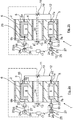
- a hydraulic damping bearing 1 which has a bearing outer part 2, which has, for example, a cylindrical sleeve shape.
- the bearing 1 further comprises a received inside the bearing outer part 2, here also exemplary cylindrical sleeve-like design bearing inner part 3, which is connected to the bearing outer part 2 by means of an elastomeric body 4.
- the elastomeric body 4 can be vulcanized, for example, both on the bearing inner part 3 and on the bearing outer part 2.
- the elastomeric body 4 can also be vulcanized on only one of the two components (bearing outer part 2, bearing inner part 3), for example, be pressed on the bearing inner part 3 and then to form a bias in the elastomer body 4 in the bearing outer part.
- the bearing 1 in the elastomeric body 4 in the vehicle longitudinal axis direction x selected here by way of example x two opposite each other with respect to the bearing inner part 3 and filled with a hydraulic fluid 5 chambers 6, 7.
- each one made of a same or different elastomeric material elastomer stop 8, 9 is formed, which serves to Wegbegrenzung.
- the elastomeric body 4 is exemplarily formed circumferentially around the bearing inner part 3, but could also be formed by two spaced-apart elastomeric blocks. Likewise, in the elastomer body 4, of course, further chambers, recesses or the like are formed, but this is not shown here for reasons of clarity.
- each of the chambers 6, 7 leads in each case in the elastomer body 4 extending or integrally formed there channel portion 6a, 7a, wherein the channel sections 6a, 7a in an exemplary here outside of the elastomeric body 4 extending connecting portion 10 (for example, a pipe, a Channel or the like) open, in which an electrically controllable throttle valve 11 is arranged, by means of which the flow cross-section and thus the flow through the connecting portion 10 in dependence on by means of a control device 17 predeterminable damping parameters can be set or changed.
- the two channel sections 6a, 7a thus form, together with the connecting section 10, a flow channel 12, via which hydraulic fluid can flow from one chamber into the other chamber when the throttle valve 11 is open, as described in US Pat Fig.
- Fig. 2a is this compared to the initial state ( Fig. 1 ) Varied chamber volume of the chambers 6, 7 dash-dotted line, the dash-dotted line symbolizing the starting position.
- the damping characteristic or the damping maximum can be set or changed or predetermined by appropriate selection of the flow cross section of the throttle valve 11, which is preferably done by means of the control device 17.
- the damping characteristic can be adjusted specifically to the requirements during driving.
- a connecting channel 6b, 7b lying from the flow channel 12 on the opposite side of the channel sections 6a, 7a in the vehicle transverse direction y leads away from each of the chambers 6, 7.
- the connecting channels 6b, 7b are formed so that they extend in the elastomer body 4 and are integrally formed there.
- the two connecting channels 6b, 7b are in each case flow-connected by means of a hose and / or pipe 18, 19 to a compensating volume device 20, 21, wherein a preferably spring-loaded check valve 22, 23 is integrated into each of the hose and / or pipe lines 18, 19 by way of example is that as electrically controllable check valve 22, 23 here is also exemplarily also connected to the control device 17 by signal technology or electrically.
- Both the connecting channels 6b, 7b and the channel sections 6a, 7a are here preferably arranged or formed so that they are not or not so compressed in a corresponding pressurization that no liquid flow is possible.
- the compensating volume device 20 in each case comprises a housing 24 in which, separated by a flexible and elastic membrane 25, a gas volume 26 with a defined gas pressure and, secondly, a liquid volume 27 are accommodated.
- the liquid received in the housing 24 of the compensation volume device 20 or 21 is preferably the same hydraulic fluid 5 as is received in the chambers 6, 7.
- the bearing stiffness of the bearing 1 can be adjusted in a simple manner in which by transferring the check valve 22 and / or 23 in its open position (by appropriate control via the control device 17) ensures that hydraulic fluid 5 from the chamber 6 and / or 7 can flow into the compensating volume device 20 and / or 21.
- the lower chamber 7 is subjected to pressure, whereby liquid 5 from the chamber 7 via the connecting channel 7b and the hose and / or pipe 19 with open check valve 23 can flow into the compensating volume device 21.
- liquid can be sucked out of the compensating volume device 20 via the check valve 22 and a chamber 6, which is subjected to tensile stress via the connecting channel 6b and the hose and / or pipe line 18, and flow into the chamber 6, so that there can be no cavity-promoting negative pressure.
- the throttle valve 11 is first closed and thus the flow connection between the chambers 6, 7 shut off via the flow channel 12. Further, the chamber 7 associated check valve 23 is transferred to the open position and the chamber 6 associated check valve 22 in the closed position, so that at a relative displacement of the bearing inner part 3 relative to the bearing outer part 2 and consequent pressure load of the chamber 7 hydraulic fluid from the chamber. 7 flows into the compensating volume device 21, while at the same time the claimed to train chamber 6 sucks hydraulic fluid from the chamber 6 associated Ausretesvolumen worn 20 and thus the bearing 1 is displaced in the direction of the chamber 7.
- the corresponding flow processes are indicated by the arrows 29 and 30 in FIG Fig. 2b shown schematically.
- check valves 22, 23 are designed so that they allow in the closed state, only an overflow of the respective compensating volume means 20 and 21 in the direction of chamber 6 and 7, not against a backflow or overflow of hydraulic fluid 5 from the chamber 6 and 7 in the compensating volume device 20 and 21, is in the in Fig. 2b example shown ensures that even with a discharge of the bearing 1 of the force F and a consequent (not shown here) strain relief of the chamber 6 no liquid from the chamber 6 can flow back into the compensation volume device 20.
- liquid can be sucked from the compensating volume device 21 into the chamber 7 in this case with an increase in volume or an expansion of the chamber 7, since the local non-return valve 23 is in the open position in which the flow connection is released in both directions.
- the bearing 1 thus continues to pump in the desired direction with such a switching position of the throttle valve 11 or the check valves 22, 23, wherein it continues to stiffen independently until an equilibrium is established.
- the switching position of the valves can be changed again and the desired damping characteristic or the desired bearing stiffness can be adjusted in the manner described above.
Claims (15)
- Palier à amortissement hydraulique pour un châssis d'un véhicule, en particulier d'un véhicule automobile, avec un premier élément de palier, qui est relié à un premier composant, et avec un deuxième élément de palier, qui est relié à un deuxième composant, dans lequel au moins un corps élastomère est agencé entre le premier élément de palier et le deuxième élément de palier, lequel délimite au moins en partie au moins deux chambres reliées l'une à l'autre du point de vue de la technique d'écoulement au moyen d'un dispositif de débordement ainsi que remplies d'un fluide de sorte que lors d'un mouvement relatif entre le premier et le deuxième élément de palier et d'une charge de pression et/ou compression qui en résulte d'au moins une chambre, le fluide déborde de cette au moins une chambre par le biais de l'au moins un dispositif de débordement dans l'au moins une autre chambre sollicitée de préférence en traction, dans lequel le dispositif de débordement (12) est couplé pour le réglage de la caractéristique d'amortissement du palier avec un dispositif de soupape (11) pour la coupure ou la régulation du débit par le dispositif de débordement (12), caractérisé en ce que chacune des chambres (6, 7) est couplée, avec un dispositif de volume de compensation (20, 21) pouvant être couplé au moyen d'un dispositif de coupure (22, 23), qui peut être relié du point de vue de la technique d'écoulement pour le réglage de la rigidité de palier avec le volume de chambre respectivement associé.
- Palier selon la revendication 1, caractérisé en ce
que le dispositif de coupure (22, 23) associé à chaque dispositif de volume de compensation (20, 21) est couplé avec un dispositif de commande (17), de préférence un dispositif de commande électrique, au moyen duquel le dispositif de coupure (22, 23) peut être commandé en fonction d'états de palier définis de sorte quea) dans une position ouverte du dispositif de coupure (22, 23), la liaison d'écoulement entre le dispositif de volume de compensation (20, 21) et la chambre (6, 7) respectivement associée est libérée dans les deux directions d'écoulement,
oub) dans une position fermée du dispositif de coupure (22, 23), la liaison d'écoulement entre le dispositif de volume de compensation (20, 21) et la chambre (6, 7) respectivement associée est bloquée dans une direction d'écoulement de sorte que seul du fluide du dispositif de volume de compensation (20, 21) peut entrer dans la chambre (6, 7) respectivement associée. - Palier selon la revendication 1 ou 2, caractérisé en ce que le dispositif de coupure (22, 23) est formé respectivement par une soupape antiretour ouvrable au moyen d'un dispositif de commande, qui dans la position fermée bloque le débit en direction du dispositif de volume de compensation (20, 21) et le libère en direction de la chambre (6, 7) respectivement associée.
- Palier selon la revendication 3, caractérisé en ce que la soupape antiretour (22, 23), de préférence une soupape antiretour sollicitée par ressort, est réalisée de sorte qu'elle libère dans la position fermée le débit en direction de la chambre (6, 7) respectivement associée seulement en fonction de l'atteinte d'une valeur seuil définie, de préférence d'une différence de pression définie entre le dispositif de volume de compensation (20, 21) et la chambre (6, 7) associée, de manière préférée entre toutes seulement après le dépassement d'une valeur seuil de dépression dans la chambre (6, 7) sollicitée en traction.
- Palier selon l'une quelconque des revendications précédentes, caractérisé en ce que le dispositif de volume de compensation (20, 21) présente un boîtier (24), dans lequel un volume de gaz (26) est reçu, qui est séparé du volume de fluide (27) pouvant y être reçu ou qui y est reçu au moyen d'un élément de séparation, en particulier au moyen d'une membrane souple et/ou élastique (25) de sorte que le volume de gaz peut être compressé lors de l'entrée de fluide.
- Palier selon la revendication 5, caractérisé en ce que dans le boîtier du dispositif de volume de compensation (20, 21), par rapport à l'état de fabrication et/ou de départ, un volume de gaz (26) défini avec une pression de gaz définie est reçu conjointement avec une quantité de fluide définie.
- Palier selon l'une quelconque des revendications précédentes, caractérisé en ce qu'une conduite de tuyau et/ou de tube (18, 19) part du dispositif de volume de compensation (20, 21), laquelle est reliée par écoulement à un canal de liaison (6b, 7b) partant de la chambre (6, 7) associée, de préférence à un canal de liaison (6b, 7b) s'étendant dans le corps élastomère (4) ou réalisé d'un seul tenant à ce niveau ainsi que non compressible lors d'une sollicitation en pression du corps élastomère (4).
- Palier selon la revendication 6, caractérisé en ce que le dispositif de coupure (22, 23) est intégré dans la conduite de tuyau et/ou de tube (18, 19).
- Palier selon l'une quelconque des revendications précédentes, caractérisé en ce que le premier élément de palier (2) réalise un élément extérieur de palier, dans lequel le deuxième élément de palier (3) est reçu en tant qu'élément intérieur de palier par l'intermédiaire d'au moins un corps élastomère (4).
- Palier selon la revendication 9, caractérisé en ce que deux chambres (6, 7) remplies de fluide sont prévues, qui, vues dans la coupe transversale, sont agencées sensiblement sur des côtés opposés de l'élément intérieur de palier.
- Palier selon l'une quelconque des revendications précédentes, caractérisé en ce que les chambres (6, 7) sont découplées du point de vue de la technique d'écoulement et/ou sont reliées du point de vue de la technique d'écoulement indépendamment de leur liaison d'écoulement respective au dispositif de volume de compensation (20, 21) respectivement associé à au moins un canal d'écoulement réalisant le dispositif de débordement (12) entre les chambres (6, 7).
- Palier selon la revendication 11, caractérisé en ce que l'au moins un canal d'écoulement (12) s'étend au moins en partie dans le corps élastomère (4).
- Palier selon la revendication 12, caractérisé en ce que respectivement une section de canal (6a, 7a), de préférence une section de canal (6a, 7a) du canal d'écoulement (12) s'étendant dans le corps élastomère (4) ou réalisé d'un seul tenant à ce niveau ainsi que non compressible lors d'une sollicitation en pression du corps élastomère (4) part des chambres (6, 7), dans lequel les sections de canal (6a, 7a) débouchent dans une section de liaison (10) du canal d'écoulement (12) s'étendant de préférence à l'extérieur du corps élastomère (4), dans lequel il est prévu de préférence que le dispositif de soupape (11) est intégré dans la section de liaison (10) pour la coupure ou la régulation du débit par le canal d'écoulement (12).
- Palier selon l'une quelconque des revendications précédentes, caractérisé en ce que le dispositif de soupape (11) est formé pour la coupure ou régulation du débit par le dispositif de débordement (12) par une soupape d'étranglement, de préférence une soupape d'étranglement à commande électrique, au moyen de laquelle la section transversale d'écoulement et ainsi le débit peut être réglé et/ou modifié par le dispositif de débordement (12) en fonction de paramètres d'amortissement pouvant être prédéfinis au moyen d'un dispositif de commande (17).
- Procédé de modification de la position d'un palier, en particulier d'un palier de châssis, dans un véhicule, en particulier dans un véhicule automobile, avec un palier à amortissement hydraulique selon l'une quelconque des revendications précédentes,
caractérisé en ce
que pour la modification de la position (réglage de trajet) du palier (1), le dispositif de soupape (11) couplé avec le dispositif de débordement (12) et ainsi la liaison d'écoulement entre les chambres (6, 7) est coupé,
qu'en outre un dispositif de coupure (23) associé à une première chambre (7) est amené dans la position ouverte et un dispositif de coupure (22) associé à une deuxième chambre (6) est amené dans la position fermée de sorte que lors d'un déplacement relatif du premier élément de palier (3) par rapport au deuxième élément de palier (4) et d'une charge de pression qui en résulte de la première chambre (7), du fluide de la première chambre (7) entre dans le dispositif de volume de compensation (21), pendant qu'en même temps la deuxième chambre (6) sollicitée en traction aspire du fluide du dispositif de volume de compensation (20) associé à la deuxième chambre (6) et le palier (1) est déplacé en direction de la première chambre (7).
Applications Claiming Priority (1)
| Application Number | Priority Date | Filing Date | Title |
|---|---|---|---|
| DE102012001655A DE102012001655A1 (de) | 2012-01-27 | 2012-01-27 | Hydraulisch dämpfendes Lager für ein Fahrwerk eines Fahrzeuges, insbesondere eines Kraftfahrzeugs, sowie Verfahren zur Veränderung der Position eines Fahrwerklagers |
Publications (3)
| Publication Number | Publication Date |
|---|---|
| EP2620302A2 EP2620302A2 (fr) | 2013-07-31 |
| EP2620302A3 EP2620302A3 (fr) | 2015-12-16 |
| EP2620302B1 true EP2620302B1 (fr) | 2019-06-26 |
Family
ID=47561157
Family Applications (1)
| Application Number | Title | Priority Date | Filing Date |
|---|---|---|---|
| EP12198216.9A Active EP2620302B1 (fr) | 2012-01-27 | 2012-12-19 | Palier à amortissement hydraulique pour un châssis de véhicule, en particulier d'un véhicule automobile, ainsi que procédé de modification de la position d'un palier de châssis |
Country Status (2)
| Country | Link |
|---|---|
| EP (1) | EP2620302B1 (fr) |
| DE (1) | DE102012001655A1 (fr) |
Families Citing this family (4)
| Publication number | Priority date | Publication date | Assignee | Title |
|---|---|---|---|---|
| DE102013013092A1 (de) | 2013-03-25 | 2014-09-25 | Carl Freudenberg Kg | Lager |
| DE102013218570A1 (de) * | 2013-09-17 | 2015-03-19 | Schaeffler Technologies Gmbh & Co. Kg | Radaufhängung und zugehöriges Fahrwerk |
| ITUA20164765A1 (it) * | 2016-06-29 | 2017-12-29 | F I B E T S P A | Boccola idraulica |
| CN112364572B (zh) * | 2020-10-20 | 2023-10-03 | 株洲时代瑞唯减振装备有限公司 | 一种用于液体橡胶复合节点的可快速更换的流道设计方法 |
Family Cites Families (12)
| Publication number | Priority date | Publication date | Assignee | Title |
|---|---|---|---|---|
| JPS6045415A (ja) * | 1983-08-19 | 1985-03-11 | Toyota Motor Corp | ショックアブソ−バの懸架ブッシュにおける圧力制御装置 |
| JPS60113707A (ja) * | 1983-11-25 | 1985-06-20 | Nissan Motor Co Ltd | 車両用懸架装置 |
| JPS60179320A (ja) * | 1984-02-25 | 1985-09-13 | Nissan Motor Co Ltd | 車両のリヤサスペンシヨン構造 |
| JPS6322712A (ja) * | 1986-07-15 | 1988-01-30 | Mazda Motor Corp | 自動車のサスペンシヨン装置 |
| JPS63231032A (ja) * | 1987-03-16 | 1988-09-27 | Toyota Motor Corp | 流体入りブツシユ |
| DE3934238A1 (de) * | 1989-10-13 | 1991-04-18 | Audi Ag | Radaufhaengung fuer kraftfahrzeuge |
| JPH1058934A (ja) * | 1996-08-22 | 1998-03-03 | Kayaba Ind Co Ltd | サスペンションのコンプライアンス制御装置 |
| DE29615913U1 (de) * | 1996-09-12 | 1998-01-15 | Weiss Wolfgang | Radaufhängung mit selbsttätiger Sturzanpassung |
| DE10145304B4 (de) * | 2001-09-14 | 2005-12-22 | Daimlerchrysler Ag | Radaufhängung mit Radträgerschubgelenken |
| DE10330877B4 (de) | 2003-07-09 | 2019-11-07 | Contitech Vibration Control Gmbh | Fahrwerkslager |
| FR2887001B1 (fr) * | 2005-06-14 | 2007-08-17 | Michelin Soc Tech | Articulation hydroelastique comportant un circuit de liaison pour le liquide |
| JP2009143380A (ja) * | 2007-12-13 | 2009-07-02 | Toyota Motor Corp | サスペンション装置 |
-
2012
- 2012-01-27 DE DE102012001655A patent/DE102012001655A1/de not_active Ceased
- 2012-12-19 EP EP12198216.9A patent/EP2620302B1/fr active Active
Non-Patent Citations (1)
| Title |
|---|
| None * |
Also Published As
| Publication number | Publication date |
|---|---|
| EP2620302A3 (fr) | 2015-12-16 |
| EP2620302A2 (fr) | 2013-07-31 |
| DE102012001655A1 (de) | 2013-08-01 |
Similar Documents
| Publication | Publication Date | Title |
|---|---|---|
| EP2129538A1 (fr) | Ensemble ressort à rigidité de suspension variable et jambe de force dotée d'un ensemble ressort de ce type | |
| WO2016206880A1 (fr) | Agencement de soupape d'amortissement dépendant de la fréquence | |
| DE102011014938A1 (de) | Dämpfungsanordnung | |
| EP2620302B1 (fr) | Palier à amortissement hydraulique pour un châssis de véhicule, en particulier d'un véhicule automobile, ainsi que procédé de modification de la position d'un palier de châssis | |
| WO1998000654A1 (fr) | Palier en elastomere a amortissement hydraulique | |
| EP2411696B1 (fr) | Palier à douille élastomère à rigidité réglable | |
| EP3224498A1 (fr) | Palier hydraulique et véhicule à moteur équipé d'un tel palier hydraulique | |
| DE102007054902B4 (de) | Anschlagelement für Hydrolager und damit ausgestattete Hydrobuchse | |
| EP2456998B1 (fr) | Dispositif amortisseur | |
| EP3158218B1 (fr) | Palier hydraulique et véhicule à moteur équipé d'un tel palier hydraulique | |
| EP1657470B1 (fr) | Elément ressort hydropneumatique pour véhicule automobile, particulièrement pour véhicule à chenilles | |
| WO2014191150A1 (fr) | Support en caoutchouc d'amortissement hydraulique | |
| DE102006013084B4 (de) | Hydraulisch dämpfendes Elastomerlager | |
| EP3126200A1 (fr) | Dispositif d'amortissement et système de freinage de véhicule à anti-patinage | |
| EP3221613B1 (fr) | Palier hydraulique et véhicule à moteur équipé d'un tel palier hydraulique | |
| DE10355199B4 (de) | Hydrolager, bei dem ein hydraulischer Anschlag durch eine verschiebbare Bodenplatte mittels magnetorheologischer Flüssigkeit steuerbar ist | |
| EP3449151B1 (fr) | Palier hydraulique, notamment palier hydraulique commandable | |
| WO2008104343A1 (fr) | Système de direction hydraulique | |
| DE102020113527A1 (de) | Axialdämpfendes, hydraulisches Elastomerlager | |
| EP1904757B1 (fr) | Support hydraulique de moteur | |
| DE102015208055B4 (de) | Hydrolager und Kraftfahrzeug mit Hydrolager | |
| EP1256755A1 (fr) | Dispositif de réduction des oscillations de pression dans les conduits hydrauliques | |
| DE102004034578A1 (de) | Gummilager mit Wegbegrenzern | |
| DE102009014965A1 (de) | Hydrolager | |
| DE102005025577A1 (de) | Vorrichtung zur Lagerung einer Brennkraftmaschine |
Legal Events
| Date | Code | Title | Description |
|---|---|---|---|
| PUAI | Public reference made under article 153(3) epc to a published international application that has entered the european phase |
Free format text: ORIGINAL CODE: 0009012 |
|
| AK | Designated contracting states |
Kind code of ref document: A2 Designated state(s): AL AT BE BG CH CY CZ DE DK EE ES FI FR GB GR HR HU IE IS IT LI LT LU LV MC MK MT NL NO PL PT RO RS SE SI SK SM TR |
|
| AX | Request for extension of the european patent |
Extension state: BA ME |
|
| PUAL | Search report despatched |
Free format text: ORIGINAL CODE: 0009013 |
|
| AK | Designated contracting states |
Kind code of ref document: A3 Designated state(s): AL AT BE BG CH CY CZ DE DK EE ES FI FR GB GR HR HU IE IS IT LI LT LU LV MC MK MT NL NO PL PT RO RS SE SI SK SM TR |
|
| AX | Request for extension of the european patent |
Extension state: BA ME |
|
| RIC1 | Information provided on ipc code assigned before grant |
Ipc: B62D 7/14 20060101ALI20151111BHEP Ipc: B60G 7/00 20060101AFI20151111BHEP Ipc: B60G 7/02 20060101ALI20151111BHEP Ipc: F16F 13/28 20060101ALI20151111BHEP Ipc: F16F 13/14 20060101ALI20151111BHEP |
|
| 17P | Request for examination filed |
Effective date: 20160616 |
|
| RBV | Designated contracting states (corrected) |
Designated state(s): AL AT BE BG CH CY CZ DE DK EE ES FI FR GB GR HR HU IE IS IT LI LT LU LV MC MK MT NL NO PL PT RO RS SE SI SK SM TR |
|
| GRAP | Despatch of communication of intention to grant a patent |
Free format text: ORIGINAL CODE: EPIDOSNIGR1 |
|
| STAA | Information on the status of an ep patent application or granted ep patent |
Free format text: STATUS: GRANT OF PATENT IS INTENDED |
|
| INTG | Intention to grant announced |
Effective date: 20190314 |
|
| GRAS | Grant fee paid |
Free format text: ORIGINAL CODE: EPIDOSNIGR3 |
|
| GRAA | (expected) grant |
Free format text: ORIGINAL CODE: 0009210 |
|
| STAA | Information on the status of an ep patent application or granted ep patent |
Free format text: STATUS: THE PATENT HAS BEEN GRANTED |
|
| AK | Designated contracting states |
Kind code of ref document: B1 Designated state(s): AL AT BE BG CH CY CZ DE DK EE ES FI FR GB GR HR HU IE IS IT LI LT LU LV MC MK MT NL NO PL PT RO RS SE SI SK SM TR |
|
| REG | Reference to a national code |
Ref country code: GB Ref legal event code: FG4D Free format text: NOT ENGLISH |
|
| REG | Reference to a national code |
Ref country code: CH Ref legal event code: EP |
|
| REG | Reference to a national code |
Ref country code: AT Ref legal event code: REF Ref document number: 1147861 Country of ref document: AT Kind code of ref document: T Effective date: 20190715 |
|
| REG | Reference to a national code |
Ref country code: DE Ref legal event code: R096 Ref document number: 502012014976 Country of ref document: DE |
|
| REG | Reference to a national code |
Ref country code: IE Ref legal event code: FG4D Free format text: LANGUAGE OF EP DOCUMENT: GERMAN |
|
| REG | Reference to a national code |
Ref country code: NL Ref legal event code: MP Effective date: 20190626 |
|
| PG25 | Lapsed in a contracting state [announced via postgrant information from national office to epo] |
Ref country code: HR Free format text: LAPSE BECAUSE OF FAILURE TO SUBMIT A TRANSLATION OF THE DESCRIPTION OR TO PAY THE FEE WITHIN THE PRESCRIBED TIME-LIMIT Effective date: 20190626 Ref country code: LT Free format text: LAPSE BECAUSE OF FAILURE TO SUBMIT A TRANSLATION OF THE DESCRIPTION OR TO PAY THE FEE WITHIN THE PRESCRIBED TIME-LIMIT Effective date: 20190626 Ref country code: FI Free format text: LAPSE BECAUSE OF FAILURE TO SUBMIT A TRANSLATION OF THE DESCRIPTION OR TO PAY THE FEE WITHIN THE PRESCRIBED TIME-LIMIT Effective date: 20190626 Ref country code: AL Free format text: LAPSE BECAUSE OF FAILURE TO SUBMIT A TRANSLATION OF THE DESCRIPTION OR TO PAY THE FEE WITHIN THE PRESCRIBED TIME-LIMIT Effective date: 20190626 Ref country code: NO Free format text: LAPSE BECAUSE OF FAILURE TO SUBMIT A TRANSLATION OF THE DESCRIPTION OR TO PAY THE FEE WITHIN THE PRESCRIBED TIME-LIMIT Effective date: 20190926 Ref country code: SE Free format text: LAPSE BECAUSE OF FAILURE TO SUBMIT A TRANSLATION OF THE DESCRIPTION OR TO PAY THE FEE WITHIN THE PRESCRIBED TIME-LIMIT Effective date: 20190626 |
|
| REG | Reference to a national code |
Ref country code: LT Ref legal event code: MG4D |
|
| PG25 | Lapsed in a contracting state [announced via postgrant information from national office to epo] |
Ref country code: LV Free format text: LAPSE BECAUSE OF FAILURE TO SUBMIT A TRANSLATION OF THE DESCRIPTION OR TO PAY THE FEE WITHIN THE PRESCRIBED TIME-LIMIT Effective date: 20190626 Ref country code: BG Free format text: LAPSE BECAUSE OF FAILURE TO SUBMIT A TRANSLATION OF THE DESCRIPTION OR TO PAY THE FEE WITHIN THE PRESCRIBED TIME-LIMIT Effective date: 20190926 Ref country code: GR Free format text: LAPSE BECAUSE OF FAILURE TO SUBMIT A TRANSLATION OF THE DESCRIPTION OR TO PAY THE FEE WITHIN THE PRESCRIBED TIME-LIMIT Effective date: 20190927 Ref country code: RS Free format text: LAPSE BECAUSE OF FAILURE TO SUBMIT A TRANSLATION OF THE DESCRIPTION OR TO PAY THE FEE WITHIN THE PRESCRIBED TIME-LIMIT Effective date: 20190626 |
|
| PG25 | Lapsed in a contracting state [announced via postgrant information from national office to epo] |
Ref country code: PT Free format text: LAPSE BECAUSE OF FAILURE TO SUBMIT A TRANSLATION OF THE DESCRIPTION OR TO PAY THE FEE WITHIN THE PRESCRIBED TIME-LIMIT Effective date: 20191028 Ref country code: RO Free format text: LAPSE BECAUSE OF FAILURE TO SUBMIT A TRANSLATION OF THE DESCRIPTION OR TO PAY THE FEE WITHIN THE PRESCRIBED TIME-LIMIT Effective date: 20190626 Ref country code: NL Free format text: LAPSE BECAUSE OF FAILURE TO SUBMIT A TRANSLATION OF THE DESCRIPTION OR TO PAY THE FEE WITHIN THE PRESCRIBED TIME-LIMIT Effective date: 20190626 Ref country code: CZ Free format text: LAPSE BECAUSE OF FAILURE TO SUBMIT A TRANSLATION OF THE DESCRIPTION OR TO PAY THE FEE WITHIN THE PRESCRIBED TIME-LIMIT Effective date: 20190626 Ref country code: EE Free format text: LAPSE BECAUSE OF FAILURE TO SUBMIT A TRANSLATION OF THE DESCRIPTION OR TO PAY THE FEE WITHIN THE PRESCRIBED TIME-LIMIT Effective date: 20190626 Ref country code: SK Free format text: LAPSE BECAUSE OF FAILURE TO SUBMIT A TRANSLATION OF THE DESCRIPTION OR TO PAY THE FEE WITHIN THE PRESCRIBED TIME-LIMIT Effective date: 20190626 |
|
| PG25 | Lapsed in a contracting state [announced via postgrant information from national office to epo] |
Ref country code: IT Free format text: LAPSE BECAUSE OF FAILURE TO SUBMIT A TRANSLATION OF THE DESCRIPTION OR TO PAY THE FEE WITHIN THE PRESCRIBED TIME-LIMIT Effective date: 20190626 Ref country code: ES Free format text: LAPSE BECAUSE OF FAILURE TO SUBMIT A TRANSLATION OF THE DESCRIPTION OR TO PAY THE FEE WITHIN THE PRESCRIBED TIME-LIMIT Effective date: 20190626 Ref country code: SM Free format text: LAPSE BECAUSE OF FAILURE TO SUBMIT A TRANSLATION OF THE DESCRIPTION OR TO PAY THE FEE WITHIN THE PRESCRIBED TIME-LIMIT Effective date: 20190626 Ref country code: IS Free format text: LAPSE BECAUSE OF FAILURE TO SUBMIT A TRANSLATION OF THE DESCRIPTION OR TO PAY THE FEE WITHIN THE PRESCRIBED TIME-LIMIT Effective date: 20191026 |
|
| PG25 | Lapsed in a contracting state [announced via postgrant information from national office to epo] |
Ref country code: TR Free format text: LAPSE BECAUSE OF FAILURE TO SUBMIT A TRANSLATION OF THE DESCRIPTION OR TO PAY THE FEE WITHIN THE PRESCRIBED TIME-LIMIT Effective date: 20190626 |
|
| PG25 | Lapsed in a contracting state [announced via postgrant information from national office to epo] |
Ref country code: DK Free format text: LAPSE BECAUSE OF FAILURE TO SUBMIT A TRANSLATION OF THE DESCRIPTION OR TO PAY THE FEE WITHIN THE PRESCRIBED TIME-LIMIT Effective date: 20190626 Ref country code: PL Free format text: LAPSE BECAUSE OF FAILURE TO SUBMIT A TRANSLATION OF THE DESCRIPTION OR TO PAY THE FEE WITHIN THE PRESCRIBED TIME-LIMIT Effective date: 20190626 |
|
| PG25 | Lapsed in a contracting state [announced via postgrant information from national office to epo] |
Ref country code: IS Free format text: LAPSE BECAUSE OF FAILURE TO SUBMIT A TRANSLATION OF THE DESCRIPTION OR TO PAY THE FEE WITHIN THE PRESCRIBED TIME-LIMIT Effective date: 20200224 |
|
| REG | Reference to a national code |
Ref country code: DE Ref legal event code: R097 Ref document number: 502012014976 Country of ref document: DE |
|
| PLBE | No opposition filed within time limit |
Free format text: ORIGINAL CODE: 0009261 |
|
| STAA | Information on the status of an ep patent application or granted ep patent |
Free format text: STATUS: NO OPPOSITION FILED WITHIN TIME LIMIT |
|
| PG2D | Information on lapse in contracting state deleted |
Ref country code: IS |
|
| REG | Reference to a national code |
Ref country code: CH Ref legal event code: PL |
|
| 26N | No opposition filed |
Effective date: 20200603 |
|
| REG | Reference to a national code |
Ref country code: BE Ref legal event code: MM Effective date: 20191231 |
|
| PG25 | Lapsed in a contracting state [announced via postgrant information from national office to epo] |
Ref country code: MC Free format text: LAPSE BECAUSE OF FAILURE TO SUBMIT A TRANSLATION OF THE DESCRIPTION OR TO PAY THE FEE WITHIN THE PRESCRIBED TIME-LIMIT Effective date: 20190626 Ref country code: SI Free format text: LAPSE BECAUSE OF FAILURE TO SUBMIT A TRANSLATION OF THE DESCRIPTION OR TO PAY THE FEE WITHIN THE PRESCRIBED TIME-LIMIT Effective date: 20190626 |
|
| PG25 | Lapsed in a contracting state [announced via postgrant information from national office to epo] |
Ref country code: IE Free format text: LAPSE BECAUSE OF NON-PAYMENT OF DUE FEES Effective date: 20191219 Ref country code: LU Free format text: LAPSE BECAUSE OF NON-PAYMENT OF DUE FEES Effective date: 20191219 |
|
| PG25 | Lapsed in a contracting state [announced via postgrant information from national office to epo] |
Ref country code: BE Free format text: LAPSE BECAUSE OF NON-PAYMENT OF DUE FEES Effective date: 20191231 Ref country code: CH Free format text: LAPSE BECAUSE OF NON-PAYMENT OF DUE FEES Effective date: 20191231 Ref country code: LI Free format text: LAPSE BECAUSE OF NON-PAYMENT OF DUE FEES Effective date: 20191231 |
|
| REG | Reference to a national code |
Ref country code: AT Ref legal event code: MM01 Ref document number: 1147861 Country of ref document: AT Kind code of ref document: T Effective date: 20191219 |
|
| PG25 | Lapsed in a contracting state [announced via postgrant information from national office to epo] |
Ref country code: CY Free format text: LAPSE BECAUSE OF FAILURE TO SUBMIT A TRANSLATION OF THE DESCRIPTION OR TO PAY THE FEE WITHIN THE PRESCRIBED TIME-LIMIT Effective date: 20190626 Ref country code: AT Free format text: LAPSE BECAUSE OF NON-PAYMENT OF DUE FEES Effective date: 20191219 |
|
| PG25 | Lapsed in a contracting state [announced via postgrant information from national office to epo] |
Ref country code: MT Free format text: LAPSE BECAUSE OF FAILURE TO SUBMIT A TRANSLATION OF THE DESCRIPTION OR TO PAY THE FEE WITHIN THE PRESCRIBED TIME-LIMIT Effective date: 20190626 Ref country code: HU Free format text: LAPSE BECAUSE OF FAILURE TO SUBMIT A TRANSLATION OF THE DESCRIPTION OR TO PAY THE FEE WITHIN THE PRESCRIBED TIME-LIMIT; INVALID AB INITIO Effective date: 20121219 |
|
| PG25 | Lapsed in a contracting state [announced via postgrant information from national office to epo] |
Ref country code: MK Free format text: LAPSE BECAUSE OF FAILURE TO SUBMIT A TRANSLATION OF THE DESCRIPTION OR TO PAY THE FEE WITHIN THE PRESCRIBED TIME-LIMIT Effective date: 20190626 |
|
| P01 | Opt-out of the competence of the unified patent court (upc) registered |
Effective date: 20230530 |
|
| PGFP | Annual fee paid to national office [announced via postgrant information from national office to epo] |
Ref country code: GB Payment date: 20231218 Year of fee payment: 12 |
|
| PGFP | Annual fee paid to national office [announced via postgrant information from national office to epo] |
Ref country code: FR Payment date: 20231220 Year of fee payment: 12 Ref country code: DE Payment date: 20231231 Year of fee payment: 12 |