EP2620302B1 - Hydraulically damped bearing for a suspension of a vehicle, in particular of a motor vehicle, and method for changing the position of a suspension bearing - Google Patents
Hydraulically damped bearing for a suspension of a vehicle, in particular of a motor vehicle, and method for changing the position of a suspension bearing Download PDFInfo
- Publication number
- EP2620302B1 EP2620302B1 EP12198216.9A EP12198216A EP2620302B1 EP 2620302 B1 EP2620302 B1 EP 2620302B1 EP 12198216 A EP12198216 A EP 12198216A EP 2620302 B1 EP2620302 B1 EP 2620302B1
- Authority
- EP
- European Patent Office
- Prior art keywords
- bearing
- flow
- chamber
- chambers
- shut
- Prior art date
- Legal status (The legal status is an assumption and is not a legal conclusion. Google has not performed a legal analysis and makes no representation as to the accuracy of the status listed.)
- Active
Links
- 238000000034 method Methods 0.000 title claims description 9
- 239000000725 suspension Substances 0.000 title claims description 5
- 239000007788 liquid Substances 0.000 claims description 38
- 238000013016 damping Methods 0.000 claims description 28
- 229920001971 elastomer Polymers 0.000 claims description 21
- 239000000806 elastomer Substances 0.000 claims description 21
- 230000001105 regulatory effect Effects 0.000 claims description 8
- 230000006835 compression Effects 0.000 claims description 4
- 238000007906 compression Methods 0.000 claims description 4
- 239000012528 membrane Substances 0.000 claims description 4
- 239000012530 fluid Substances 0.000 description 8
- 230000008859 change Effects 0.000 description 7
- 238000006073 displacement reaction Methods 0.000 description 7
- 230000008569 process Effects 0.000 description 3
- 230000000903 blocking effect Effects 0.000 description 2
- 238000005516 engineering process Methods 0.000 description 2
- 238000002955 isolation Methods 0.000 description 2
- 235000015095 lager Nutrition 0.000 description 2
- 230000003534 oscillatory effect Effects 0.000 description 2
- 238000010521 absorption reaction Methods 0.000 description 1
- 230000000712 assembly Effects 0.000 description 1
- 238000000429 assembly Methods 0.000 description 1
- 230000033228 biological regulation Effects 0.000 description 1
- 230000005540 biological transmission Effects 0.000 description 1
- 238000010276 construction Methods 0.000 description 1
- 230000001419 dependent effect Effects 0.000 description 1
- 238000010586 diagram Methods 0.000 description 1
- 230000005489 elastic deformation Effects 0.000 description 1
- 239000013536 elastomeric material Substances 0.000 description 1
- 238000009472 formulation Methods 0.000 description 1
- 230000002452 interceptive effect Effects 0.000 description 1
- 238000004519 manufacturing process Methods 0.000 description 1
- 230000007246 mechanism Effects 0.000 description 1
- 239000000203 mixture Substances 0.000 description 1
- 230000004044 response Effects 0.000 description 1
- 238000000926 separation method Methods 0.000 description 1
- 230000003068 static effect Effects 0.000 description 1
- 230000001629 suppression Effects 0.000 description 1
Images

Classifications
-
- B—PERFORMING OPERATIONS; TRANSPORTING
- B60—VEHICLES IN GENERAL
- B60G—VEHICLE SUSPENSION ARRANGEMENTS
- B60G7/00—Pivoted suspension arms; Accessories thereof
- B60G7/006—Attaching arms to sprung or unsprung part of vehicle, characterised by comprising attachment means controlled by an external actuator, e.g. a fluid or electrical motor
-
- B—PERFORMING OPERATIONS; TRANSPORTING
- B60—VEHICLES IN GENERAL
- B60G—VEHICLE SUSPENSION ARRANGEMENTS
- B60G7/00—Pivoted suspension arms; Accessories thereof
- B60G7/02—Attaching arms to sprung part of vehicle
-
- F—MECHANICAL ENGINEERING; LIGHTING; HEATING; WEAPONS; BLASTING
- F16—ENGINEERING ELEMENTS AND UNITS; GENERAL MEASURES FOR PRODUCING AND MAINTAINING EFFECTIVE FUNCTIONING OF MACHINES OR INSTALLATIONS; THERMAL INSULATION IN GENERAL
- F16F—SPRINGS; SHOCK-ABSORBERS; MEANS FOR DAMPING VIBRATION
- F16F13/00—Units comprising springs of the non-fluid type as well as vibration-dampers, shock-absorbers, or fluid springs
- F16F13/04—Units comprising springs of the non-fluid type as well as vibration-dampers, shock-absorbers, or fluid springs comprising both a plastics spring and a damper, e.g. a friction damper
- F16F13/06—Units comprising springs of the non-fluid type as well as vibration-dampers, shock-absorbers, or fluid springs comprising both a plastics spring and a damper, e.g. a friction damper the damper being a fluid damper, e.g. the plastics spring not forming a part of the wall of the fluid chamber of the damper
- F16F13/08—Units comprising springs of the non-fluid type as well as vibration-dampers, shock-absorbers, or fluid springs comprising both a plastics spring and a damper, e.g. a friction damper the damper being a fluid damper, e.g. the plastics spring not forming a part of the wall of the fluid chamber of the damper the plastics spring forming at least a part of the wall of the fluid chamber of the damper
- F16F13/14—Units of the bushing type, i.e. loaded predominantly radially
- F16F13/1418—Units of the bushing type, i.e. loaded predominantly radially characterised by the location or shape of the equilibration chamber
-
- F—MECHANICAL ENGINEERING; LIGHTING; HEATING; WEAPONS; BLASTING
- F16—ENGINEERING ELEMENTS AND UNITS; GENERAL MEASURES FOR PRODUCING AND MAINTAINING EFFECTIVE FUNCTIONING OF MACHINES OR INSTALLATIONS; THERMAL INSULATION IN GENERAL
- F16F—SPRINGS; SHOCK-ABSORBERS; MEANS FOR DAMPING VIBRATION
- F16F13/00—Units comprising springs of the non-fluid type as well as vibration-dampers, shock-absorbers, or fluid springs
- F16F13/04—Units comprising springs of the non-fluid type as well as vibration-dampers, shock-absorbers, or fluid springs comprising both a plastics spring and a damper, e.g. a friction damper
- F16F13/26—Units comprising springs of the non-fluid type as well as vibration-dampers, shock-absorbers, or fluid springs comprising both a plastics spring and a damper, e.g. a friction damper characterised by adjusting or regulating devices responsive to exterior conditions
- F16F13/28—Units comprising springs of the non-fluid type as well as vibration-dampers, shock-absorbers, or fluid springs comprising both a plastics spring and a damper, e.g. a friction damper characterised by adjusting or regulating devices responsive to exterior conditions specially adapted for units of the bushing type
-
- B—PERFORMING OPERATIONS; TRANSPORTING
- B60—VEHICLES IN GENERAL
- B60G—VEHICLE SUSPENSION ARRANGEMENTS
- B60G2204/00—Indexing codes related to suspensions per se or to auxiliary parts
- B60G2204/10—Mounting of suspension elements
- B60G2204/14—Mounting of suspension arms
- B60G2204/143—Mounting of suspension arms on the vehicle body or chassis
-
- B—PERFORMING OPERATIONS; TRANSPORTING
- B60—VEHICLES IN GENERAL
- B60G—VEHICLE SUSPENSION ARRANGEMENTS
- B60G2204/00—Indexing codes related to suspensions per se or to auxiliary parts
- B60G2204/40—Auxiliary suspension parts; Adjustment of suspensions
- B60G2204/41—Elastic mounts, e.g. bushings
- B60G2204/4106—Elastokinematic mounts
- B60G2204/41062—Elastokinematic mounts hydromounts; interconnected mounts
Definitions
- the invention relates to a hydraulically damping bearing for a chassis of a vehicle, in particular of a motor vehicle, according to the preamble of claim 1 and a method for changing the position of a chassis bearing in a vehicle, in particular in a motor vehicle, according to the preamble of claim 15.
- a bearing according to the preamble of claim 1 is known from JP S60 113707 known.
- Chassis bearings must meet a variety of requirements, including but not limited to the absorption of forces, the damping of vibrations, the ability to elastic deformation and the isolation of noise.
- the targeted damping of vibrations can be achieved, for example, by using hydraulically damping bearings, also referred to as hydraulic bearings.
- hydraulically damping bearings also referred to as hydraulic bearings.
- there are driving situations which require a soft static bearing characteristic with a large deformation path whereas in other driving situations a stiff bearing characteristic with a small deformation path may be desired.
- An example of such a bearing is from the DE 103 30 877 A1 in which an elastomeric body is arranged between an outer and an inner bearing sleeve, in which two chambers filled with liquid are formed.
- the chambers are separated from each other and arranged symmetrically to both sides of the longitudinal axis of the inner bearing sleeve and each have a stop on a common transverse axis of the inner bearing sleeve and at a distance to a corresponding counter stop surface is disposed within the chamber.
- the stops are designed to be displaceable and acted upon by pressure such that they can be moved along a common transverse axis and the inner bearing sleeve is fixed relative to the outer bearing sleeve in a current state of vibration.
- the pressure required for fixing is fully established only when both attacks abut against their counter stop surfaces. With such a trained chassis bearing the bearing stiffness should be increased at any time by a multiple.
- a hydraulically damping bearing for a chassis of a vehicle, in particular a motor vehicle which has a first bearing part, which is connected to a first component, and which has a second bearing part, which is connected to a second component.
- At least one elastomeric body is arranged between the first bearing part and the second bearing part, at least two of which fluidly connected by means of an overflow and filled with a liquid, in particular spaced apart, such chambers at least partially limited that during a relative movement between the first and the second bearing part and a consequent pressure load and / or compression at least a chamber, the liquid flows from this at least one chamber via the at least one overflow into the at least one other, preferably zugbelastete chamber, wherein the overflow is coupled for adjusting the damping characteristic of the bearing with a valve means for shutting off or regulating the flow through the overflow ,
- each of the chambers is coupled to a compensating volume device which can be shut off by means of a shut-off device and which can be fluidically connected to the respectively assigned chamber volume in order to set the bearing stiffness.
- the stiffness circuit of the bearing is thus functionally separated from the adjustment of the damping characteristic of the bearing, resulting in considerable freedom with regard to the adjustment of the damping characteristic and / or the adjustment of the bearing stiffness.
- the overflow valve means for blocking or regulating the flow through the overflow a targeted adjustment of the maximum attenuation can be made, depending on the currently prevailing driving or operating conditions.
- valve device for shutting off or regulating the flow through the overflow device that is to say with such a variably adjustable valve device, a targeted damping of vibrations adapted to the respective driving situation can thus be made possible, wherein at the same time a state is set which limits the isolation of higher-frequency noises allows. In other words, that means As a result, the maximum attenuation can be targeted to different frequencies.
- each of the chambers is coupled to a compensation volume device.
- each chamber is assigned its own compensation volume and thus its own compensation volume device.
- the shut-off device associated with each equalizing volume device is coupled to a control device, preferably an electric control device, by means of which the shut-off device can be controlled in dependence on defined storage conditions such that, first, the flow connection between in an open position of the shut-off device the compensating volume device and the respective associated chamber is released in both flow directions.
- a control device preferably an electric control device
- liquid can then flow from the compensating volume device into the assigned chamber again in a quick and simple manner.
- the flow connection between the compensating volume device and the respectively assigned chamber is blocked in a flow direction in such a way that only liquid flows out of the Compensation volume device can flow into the respective associated chamber.
- the bearing thus has a high or maximum bearing rigidity in the area of the chamber locked in this way, since the overflow of the liquid into the compensating volume device is prevented.
- any positions of the shut-off device are possible or adjustable, in which the shut-off device is more or less open or closed.
- the choice of the respective intermediate position depends on the bearing rigidity desired for the respective driving situation, which is stored, for example, in a characteristic diagram of a control device with reference to different driving situations.
- the control device itself can be part of a separate control device, for example, or it can also be part of another vehicle-mounted control unit, for example a component of an engine control unit, to name just one example.
- the shut-off device is formed in each case by a non-return valve which can be opened by means of a control device which, in the closed position, blocks the flow in the direction of the compensating volume device and releases it in the direction of the respectively assigned chamber.
- the check valve may be, for example, a spring-loaded check valve, but other non-return valves may be used.
- Such a check valve is preferably designed so that it in the closed position, the flow in the direction of the respective associated chamber only in response to the achievement of a defined threshold, preferably a defined pressure difference between the compensating volume and associated chamber, most preferably only after exceeding a vacuum threshold in the loaded on train chamber releases.
- a defined threshold preferably a defined pressure difference between the compensating volume and associated chamber, most preferably only after exceeding a vacuum threshold in the loaded on train chamber releases.
- the compensating volume device has a housing in which a gas volume is accommodated, which is separated from the liquid volume accommodated or received therein by means of a separating element in such a way that the gas volume can be compressed with inflowing liquid.
- the separating element may in this case be formed in particular by a flexible and / or elastic membrane which is fixed in the housing.
- the compensating volume device is constructed so that received in the housing of the compensating volume device, based on the manufacturing and / or initial state, a defined gas volume with a defined gas pressure together with a defined amount of liquid is.
- the gas pressure may be adjusted according to the function requirement to provide a desired gas cushion or gas spring.
- connection of the compensating volume device to the respectively assigned chamber can take place in different ways.
- a hose and / or pipeline leads away from the compensating volume device, which is flow-connected to a connecting channel leading away from the associated chamber.
- the hose and / or pipe can be both rigid and flexible or even partially rigid and partially flexible.
- the connecting channel can in turn run in the elastomeric body or be formed integrally there.
- the connecting channel should preferably be arranged or designed such that it remains dimensionally stable under pressure or negative pressure, so that the cross-sectional area is not changed, so that the flow connection to the compensating volume device remains functional.
- the shut-off device is integrated into the hose and / or pipe, which regularly run outside of the elastomer body or the bearing structure.
- the bearing is a nested bearing, in which the first bearing part forms a bearing outer part, in which the second bearing part is received as a bearing inner part with the interposition of at least one elastomer body.
- a bearing structure is advantageous in which the chambers are each formed or received in total in the elastomer body, although bearing configurations in which the chambers are only partially limited by the elastomer body, in principle conceivable and possible.
- a concrete structure is advantageous, in particular with regard to hydraulically damping chassis bearings, in which two chambers filled with liquid are provided, which are seen in cross-section, arranged substantially on opposite sides of the bearing inner part.
- Such a bearing structure is advantageous for a variety of concrete bearing applications.
- the chambers are fluidically decoupled or independent of their respective flow connection with the respectively assigned compensation volume device, as has already been described above, with at least one overflow device forming between the chambers Flow channel are fluidically connected.
- This flow channel can basically run completely in the elastomer body.
- the flow channel extends only partially in the elastomer body.
- a channel section preferably leads away in the elastomeric body or integrally formed there as well as in a negative / positive pressure of the elastomer body sufficiently dimensionally stable channel portion of the flow channel leads away.
- the channel sections preferably open in an advantageous manner outside the elastomer body extending connecting portion of the flow channel.
- the valve device for blocking or regulating the flow for the flow channel is integrated into the connecting section.
- the valve device for shutting off or regulating the flow through the overflow device can in principle be designed in many different ways. Particularly preferred is a structure in which this is formed by a throttle valve, preferably by an electrically controllable throttle valve, by means of which the flow cross-section and thus the flow through the overflow can be adjusted or changed depending on by means of a control device specifiable Dämpfungsparamater.
- a throttle valve device or arrangement can be integrated into the bearing structure in a simple and functionally reliable manner and, by simple actuation, makes it possible to set the respective damping characteristic given in relation to the respective driving situation.
- the respective maximum attenuation values, based on the respective driving situation or operating situation, may in turn be stored, for example, in a map of the control device, which in turn may also be designed as a separate control device or may also be part of another control device present on the vehicle, for example a component an engine control unit can be.
- the object of the invention is further achieved by a method for changing the position of a bearing, in particular a chassis bearing, in a vehicle, especially in a motor vehicle, in which for changing the position (displacement adjustment) of the bearing coupled to the overflow valve device and thus the Flow connection between the chambers is shut off. Furthermore, a shut-off device associated with a first chamber is transferred into the open position and a shut-off device associated with a second chamber is moved into the closed position, so that liquid is transferred from the first chamber into the first chamber when the first bearing part is relatively displaced relative to the second bearing part and thereby subjected to compressive stress Equalizing volume device flows while at the same time the chamber claimed to train sucks liquid from the second chamber associated Aus Sammlungsvolumen liked.
- Such a change in position or displacement adjustment according to the invention can thus be achieved in an energy-saving and component-saving manner, as can be dispensed with electrical actuators and hydraulic pressure generation, which also brings a significant space and weight savings.
- a hydraulic damping bearing 1 which has a bearing outer part 2, which has, for example, a cylindrical sleeve shape.
- the bearing 1 further comprises a received inside the bearing outer part 2, here also exemplary cylindrical sleeve-like design bearing inner part 3, which is connected to the bearing outer part 2 by means of an elastomeric body 4.
- the elastomeric body 4 can be vulcanized, for example, both on the bearing inner part 3 and on the bearing outer part 2.
- the elastomeric body 4 can also be vulcanized on only one of the two components (bearing outer part 2, bearing inner part 3), for example, be pressed on the bearing inner part 3 and then to form a bias in the elastomer body 4 in the bearing outer part.
- the bearing 1 in the elastomeric body 4 in the vehicle longitudinal axis direction x selected here by way of example x two opposite each other with respect to the bearing inner part 3 and filled with a hydraulic fluid 5 chambers 6, 7.
- each one made of a same or different elastomeric material elastomer stop 8, 9 is formed, which serves to Wegbegrenzung.
- the elastomeric body 4 is exemplarily formed circumferentially around the bearing inner part 3, but could also be formed by two spaced-apart elastomeric blocks. Likewise, in the elastomer body 4, of course, further chambers, recesses or the like are formed, but this is not shown here for reasons of clarity.
- each of the chambers 6, 7 leads in each case in the elastomer body 4 extending or integrally formed there channel portion 6a, 7a, wherein the channel sections 6a, 7a in an exemplary here outside of the elastomeric body 4 extending connecting portion 10 (for example, a pipe, a Channel or the like) open, in which an electrically controllable throttle valve 11 is arranged, by means of which the flow cross-section and thus the flow through the connecting portion 10 in dependence on by means of a control device 17 predeterminable damping parameters can be set or changed.
- the two channel sections 6a, 7a thus form, together with the connecting section 10, a flow channel 12, via which hydraulic fluid can flow from one chamber into the other chamber when the throttle valve 11 is open, as described in US Pat Fig.
- Fig. 2a is this compared to the initial state ( Fig. 1 ) Varied chamber volume of the chambers 6, 7 dash-dotted line, the dash-dotted line symbolizing the starting position.
- the damping characteristic or the damping maximum can be set or changed or predetermined by appropriate selection of the flow cross section of the throttle valve 11, which is preferably done by means of the control device 17.
- the damping characteristic can be adjusted specifically to the requirements during driving.
- a connecting channel 6b, 7b lying from the flow channel 12 on the opposite side of the channel sections 6a, 7a in the vehicle transverse direction y leads away from each of the chambers 6, 7.
- the connecting channels 6b, 7b are formed so that they extend in the elastomer body 4 and are integrally formed there.
- the two connecting channels 6b, 7b are in each case flow-connected by means of a hose and / or pipe 18, 19 to a compensating volume device 20, 21, wherein a preferably spring-loaded check valve 22, 23 is integrated into each of the hose and / or pipe lines 18, 19 by way of example is that as electrically controllable check valve 22, 23 here is also exemplarily also connected to the control device 17 by signal technology or electrically.
- Both the connecting channels 6b, 7b and the channel sections 6a, 7a are here preferably arranged or formed so that they are not or not so compressed in a corresponding pressurization that no liquid flow is possible.
- the compensating volume device 20 in each case comprises a housing 24 in which, separated by a flexible and elastic membrane 25, a gas volume 26 with a defined gas pressure and, secondly, a liquid volume 27 are accommodated.
- the liquid received in the housing 24 of the compensation volume device 20 or 21 is preferably the same hydraulic fluid 5 as is received in the chambers 6, 7.
- the bearing stiffness of the bearing 1 can be adjusted in a simple manner in which by transferring the check valve 22 and / or 23 in its open position (by appropriate control via the control device 17) ensures that hydraulic fluid 5 from the chamber 6 and / or 7 can flow into the compensating volume device 20 and / or 21.
- the lower chamber 7 is subjected to pressure, whereby liquid 5 from the chamber 7 via the connecting channel 7b and the hose and / or pipe 19 with open check valve 23 can flow into the compensating volume device 21.
- liquid can be sucked out of the compensating volume device 20 via the check valve 22 and a chamber 6, which is subjected to tensile stress via the connecting channel 6b and the hose and / or pipe line 18, and flow into the chamber 6, so that there can be no cavity-promoting negative pressure.
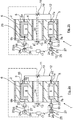
- the throttle valve 11 is first closed and thus the flow connection between the chambers 6, 7 shut off via the flow channel 12. Further, the chamber 7 associated check valve 23 is transferred to the open position and the chamber 6 associated check valve 22 in the closed position, so that at a relative displacement of the bearing inner part 3 relative to the bearing outer part 2 and consequent pressure load of the chamber 7 hydraulic fluid from the chamber. 7 flows into the compensating volume device 21, while at the same time the claimed to train chamber 6 sucks hydraulic fluid from the chamber 6 associated Ausretesvolumen worn 20 and thus the bearing 1 is displaced in the direction of the chamber 7.
- the corresponding flow processes are indicated by the arrows 29 and 30 in FIG Fig. 2b shown schematically.
- check valves 22, 23 are designed so that they allow in the closed state, only an overflow of the respective compensating volume means 20 and 21 in the direction of chamber 6 and 7, not against a backflow or overflow of hydraulic fluid 5 from the chamber 6 and 7 in the compensating volume device 20 and 21, is in the in Fig. 2b example shown ensures that even with a discharge of the bearing 1 of the force F and a consequent (not shown here) strain relief of the chamber 6 no liquid from the chamber 6 can flow back into the compensation volume device 20.
- liquid can be sucked from the compensating volume device 21 into the chamber 7 in this case with an increase in volume or an expansion of the chamber 7, since the local non-return valve 23 is in the open position in which the flow connection is released in both directions.
- the bearing 1 thus continues to pump in the desired direction with such a switching position of the throttle valve 11 or the check valves 22, 23, wherein it continues to stiffen independently until an equilibrium is established.
- the switching position of the valves can be changed again and the desired damping characteristic or the desired bearing stiffness can be adjusted in the manner described above.
Landscapes
- Engineering & Computer Science (AREA)
- General Engineering & Computer Science (AREA)
- Mechanical Engineering (AREA)
- Combined Devices Of Dampers And Springs (AREA)
Description
Die Erfindung betrifft ein hydraulisch dämpfendes Lager für ein Fahrwerk eines Fahrzeugs, insbesondere eines Kraftfahrzeugs, nach dem Oberbegriff des Anspruchs 1 sowie ein Verfahren zur Veränderung der Position eines Fahrwerklagers in einem Fahrzeug, insbesondere in einem Kraftfahrzeug, nach dem Oberbegriff des Anspruchs 15.The invention relates to a hydraulically damping bearing for a chassis of a vehicle, in particular of a motor vehicle, according to the preamble of claim 1 and a method for changing the position of a chassis bearing in a vehicle, in particular in a motor vehicle, according to the preamble of
Ein Lager nach dem Oberbegriff des Anspruchs 1 ist aus der
Fahrwerklager müssen eine Vielzahl von Anforderungen erfüllen, wozu unter anderem die Aufnahme von Kräften, die Dämpfung von Schwingungen, die Fähigkeit zur elastischen Verformung und auch die Isolation von Geräusch gehören. Die gezielte Dämpfung von Schwingungen kann dabei zum Beispiel durch Verwendung von auch als Hydrolagern bezeichneten hydraulisch dämpfenden Lagern erzielt werden. Weiterhin gibt es Fahrsituationen, welche eine weiche statische Lagerkennlinie mit großem Verformungsweg erfordern, während hingegen bei anderen Fahrsituationen eine steife Lagerkennlinie mit geringem Verformungsweg erwünscht sein kann. Ein Beispiel für ein derartiges Lager ist aus der
Problematisch bei einem derartigen Lageraufbau ist jedoch, dass eine hohe Dämpfung von Schwingungen, wie zum Beispiel im Bereich der Achseigenfrequenzen des Fahrwerks, stets mit einer Erhöhung der dynamischen Steifigkeiten im höherfrequenten Bereich einhergeht, was auch als dynamische Verhärtung bezeichnet wird. Daraus resultiert schließlich eine verstärkte Übertragung von Geräuschen der Radaufhängung in die Karosserie, was unerwünscht ist. Zudem ist eine hohe Dämpfung bei hydraulisch dämpfenden Lagern nur in einem schmalen Frequenzbereich möglich. Des Weiteren kann es insbesondere in den auf Zug belasteten Kammern und einer damit einhergehenden Volumenvergrößerung dieser Kammern zum Auftreten von Unterdrücken kommen, die zu einer Kavitation im Kammerbereich und damit auch zu Beschädigungen des Lagers führen können. Abgesehen davon treten durch diese Kavitationsereignisse auch vom Fahrer wahrnehmbare und als extrem störend empfundene Geräusche auf.The problem with such a bearing structure, however, is that a high damping of vibrations, such as in the range of Achigenfrequeten the chassis, always accompanied by an increase in the dynamic stiffness in the higher-frequency range, which is also referred to as dynamic hardening. This ultimately results in an increased transmission of noise of the suspension in the bodywork, which is undesirable. In addition, high damping in hydraulically damping bearings is possible only in a narrow frequency range. Furthermore, in particular in the chambers loaded with tension and a concomitant increase in the volume of these chambers, it is possible for suppression to occur which can lead to cavitation in the chamber area and thus also to damage to the bearing. Apart from that occur by these cavitation events also perceptible by the driver and perceived as extremely disturbing noises.
Ein weiterer wesentlicher Nachteil derartiger herkömmlicher Lageraufbauten ist, dass zur Veränderung der Position eines derartigen Fahrwerklagers in einem Fahrzeug, was auch Wegverstellung genannt wird, in Verbindung mit einer hydraulischen Aktuatorik stets Aggregate zur Druckbereitstellung erforderlich sind, deren Platz- und Leistungsbedarf hoch ist. Eine Lösung mittels elektrischer Aktoren erfordert dagegen stets eine komplizierte Verstellmechanik.Another major disadvantage of such conventional bearing assemblies is that to change the position of such a chassis bearing in a vehicle, which is also called displacement adjustment, in combination with a hydraulic actuators always units for pressure supply are required, the space and power consumption is high. A solution By contrast, electrical actuators always require a complicated adjustment mechanism.
Demgegenüber ist es Aufgabe der vorliegenden Erfindung, ein hydraulisch dämpfendes Lager für ein Fahrwerk eines Fahrzeugs, insbesondere eines Kraftfahrzeugs, zur Verfügung zu stellen, das bei relativ einfachem Aufbau auf funktionssichere Weise eine gewünschte Steifigkeitseinstellung ermöglicht, ebenso wie es eine für unterschiedliche Fahrsituationen gezielte Dämpfung von Schwingungen ermöglicht. Zudem ist es eine weitere Aufgabe der vorliegenden Erfindung, ein Verfahren zur Veränderung der Position eines Lagers, insbesondere eines Fahrwerklagers, in einem Fahrzeug, insbesondere in einem Kraftfahrzeug, zur Verfügung zu stellen, mittels dem die Veränderung der Position (Wegverstellung) des Lagers auf bauteiltechnisch einfache sowie funktionssichere Weise durchgeführt werden kann.In contrast, it is an object of the present invention to provide a hydraulically damping bearing for a chassis of a vehicle, in particular a motor vehicle, which enables a desired stiffness adjustment with a relatively simple structure in a functionally reliable manner, as well as targeted for different driving situations damping of Allows vibrations. In addition, it is a further object of the present invention to provide a method for changing the position of a bearing, in particular a chassis bearing, in a vehicle, in particular in a motor vehicle, by means of which the position change (displacement adjustment) of the bearing is based on component technology simple and functionally reliable way can be performed.
Diese Aufgabe wird gelöst mit den Merkmalen der unabhängigen Patentansprüche. Vorteilhafte Ausgestaltungen hierzu sind Gegenstand der darauf rückbezogenen Unteransprüche.This object is achieved with the features of the independent claims. Advantageous embodiments thereof are the subject of the dependent claims.
Gemäß Patentanspruch 1 wird ein hydraulisch dämpfendes Lager für ein Fahrwerk eines Fahrzeugs, insbesondere eines Kraftfahrzeugs, vorgeschlagen, das ein erstes Lagerteil aufweist, das mit einem ersten Bauteil verbunden ist, und das ein zweites Lagerteil aufweist, das mit einem zweiten Bauteil verbunden ist. Zwischen dem ersten Lagerteil und dem zweiten Lagerteil ist wenigstens ein Elastomerkörper angeordnet, der wenigstens zwei miteinander strömungstechnisch mittels einer Überströmeinrichtung verbundene sowie mit einer Flüssigkeit befüllte, insbesondere voneinander beabstandete, Kammern dergestalt wenigstens teilweise begrenzt, dass bei einer Relativbewegung zwischen dem ersten und dem zweiten Lagerteil und einer dadurch bedingten Druckbelastung und/oder Komprimierung wenigstens einer Kammer, die Flüssigkeit aus dieser wenigstens einen Kammer über die wenigstens eine Überströmeinrichtung in die wenigstens eine andere, vorzugsweise auf zugbelastete Kammer überströmt, wobei die Überströmeinrichtung zur Einstellung der Dämpfungscharakteristik des Lagers mit einer Ventileinrichtung zur Absperrung oder Regelung des Durchflusses durch die Überströmeinrichtung gekoppelt ist.According to claim 1, a hydraulically damping bearing for a chassis of a vehicle, in particular a motor vehicle, proposed, which has a first bearing part, which is connected to a first component, and which has a second bearing part, which is connected to a second component. At least one elastomeric body is arranged between the first bearing part and the second bearing part, at least two of which fluidly connected by means of an overflow and filled with a liquid, in particular spaced apart, such chambers at least partially limited that during a relative movement between the first and the second bearing part and a consequent pressure load and / or compression at least a chamber, the liquid flows from this at least one chamber via the at least one overflow into the at least one other, preferably zugbelastete chamber, wherein the overflow is coupled for adjusting the damping characteristic of the bearing with a valve means for shutting off or regulating the flow through the overflow ,
Erfindungsgemäß ist vorgesehen, dass jede der Kammern, mit einer, mittels einer Absperreinrichtung absperrbaren Ausgleichsvolumeneinrichtung gekoppelt ist, die zur Einstellung der Lagersteifigkeit mit dem jeweils zugeordneten Kammervolumen strömungstechnisch verbindbar ist.It is provided according to the invention that each of the chambers is coupled to a compensating volume device which can be shut off by means of a shut-off device and which can be fluidically connected to the respectively assigned chamber volume in order to set the bearing stiffness.
Mit der vorliegenden Erfindungsidee wird somit die Steifigkeitsschaltung des Lagers funktionell von der Einstellung der Dämpfungscharakteristik des Lagers abgetrennt, wodurch sich erhebliche Freiheiten im Hinblick auf die Einstellung der Dämpfungscharakteristik und/oder der Einstellung der Lagersteifigkeit ergeben. So kann durch die mit der Überströmeinrichtung gekoppelte Ventileinrichtung zur Absperrung bzw. Regelung des Durchflusses durch die Überströmeinrichtung eine gezielte Einstellung des Dämpfungsmaximums vorgenommen werden, und zwar abhängig von den jeweils gerade vorherrschenden Fahr- bzw. Betriebsbedingungen.With the present invention idea, the stiffness circuit of the bearing is thus functionally separated from the adjustment of the damping characteristic of the bearing, resulting in considerable freedom with regard to the adjustment of the damping characteristic and / or the adjustment of the bearing stiffness. Thus, by the coupled with the overflow valve means for blocking or regulating the flow through the overflow a targeted adjustment of the maximum attenuation can be made, depending on the currently prevailing driving or operating conditions.
Mit einer derartigen Ventileinrichtung zur Absperrung oder Regelung des Durchflusses durch die Überströmeinrichtung, das heißt mit einer derartigen variabel einstellbaren Ventileinrichtung, kann somit eine an die jeweilige Fahrsituation angepasste gezielte Dämpfung von Schwingungen ermöglicht werden, wobei gleichzeitig ein Zustand eingestellt wird, der die Isolation höherfrequenter Geräusche ermöglicht. Das heißt mit anderen Worten, dass hierdurch das Dämpfungsmaximum gezielt auf verschiedene Frequenzen gelegt werden kann.With such a valve device for shutting off or regulating the flow through the overflow device, that is to say with such a variably adjustable valve device, a targeted damping of vibrations adapted to the respective driving situation can thus be made possible, wherein at the same time a state is set which limits the isolation of higher-frequency noises allows. In other words, that means As a result, the maximum attenuation can be targeted to different frequencies.
Auf der anderen Seite kann alternativ oder aber auch zusätzlich dazu, und dies vor allem auch unabhängig von der Einstellung der Dämpfungscharakteristik, über die Ausgleichsvolumeneinrichtung eine einfache Einstellung der Lagersteifigkeit vorgenommen werden, zum Beispiel dergestalt, dass die Ausgleichsvolumina der Ausgleichsvolumeneinrichtung hinzu geschaltet werden, wodurch die Lagercharakteristik weicher eingestellt werden kann, was nachfolgend noch in Verbindung mit den konkreten Ausführungsformen näher beschrieben wird.On the other hand, as an alternative or in addition to this, and above all irrespective of the setting of the damping characteristic, a simple adjustment of the bearing rigidity can be made via the compensating volume device, for example such that the compensating volumes of the compensating volume device are switched in, as a result of which Bearing characteristic can be set softer, which will be described in more detail below in connection with the specific embodiments.
Mit einer derartigen erfindungsgemäßen Lösung wird somit insgesamt ein einfach aufgebautes, funktionssicheres hydraulisch dämpfendes Lager für ein Fahrwerk eines Fahrzeugs zur Verfügung gestellt, das stets optimal an die jeweilige Fahrsituation anpassbar ist.With such a solution according to the invention thus a total of a simple structure, reliable hydraulic damping bearing for a chassis of a vehicle is provided, which is always optimally adapted to the particular driving situation.
Zudem können durch den erfindungsgemäßen Aufbau kritische Unterdrücke in den Kammern, insbesondere in den auf Zug belasteten Kammern vermieden werden, da durch entsprechende Ansteuerung der Ausgleichsvolumeneinrichtung sichergestellt werden kann, dass stets ausreichend Flüssigkeit in den Kammern vorhanden ist, was hilft, Kavitation zu vermeiden.In addition, critical underpressures in the chambers, in particular in the chambers loaded on train, can be avoided by the design according to the invention since it can be ensured by appropriate control of the compensation volume device that there is always sufficient liquid in the chambers, which helps to avoid cavitation.
Mit der erfindungsgemäßen Lösung können zudem Positionsveränderungen auf einfache Weise energiesparend durchgeführt werden, ohne dass hier eine zusätzliche Aktuatorik etc. benötigt wird, was nachfolgend noch näher in Verbindung mit der erfindungsgemäßen Verfahrensführung erläutert wird.With the solution according to the invention, moreover, changes in position can be carried out in a simple manner in an energy-saving manner, without the need for additional actuators, etc., which will be explained in more detail below in connection with the method according to the invention.
Wie bereits zuvor erwähnt, kann es gegebenenfalls ausreichend sein, dass lediglich eine der Kammern mit einer Ausgleichsvolumeneinrichtung gekoppelt ist, wobei jedoch erfindungsgemäß vorgesehen ist, dass jede der Kammern mit einer Ausgleichsvolumeneinrichtung gekoppelt ist. Dadurch ergibt sich für viele Anwendungsfälle eine ausreichende Flexibilität bei der Einstellung der Lagersteifigkeit. Grundsätzlich ist es in diesem Zusammenhang auch möglich, nicht erfindungsgemäß lediglich eine einzige Ausgleichsvolumeneinrichtung vorzusehen, an die mehrere bzw. alle Kammern angeschlossen sind. Aus Gründen der Flexibilität im Hinblick auf die Zuschaltung der einzelnen Ausgleichsvolumina ist es jedoch bevorzugt und erfindungsgemäß, dass jeder Kammer ein eigenes Ausgleichsvolumen und damit eine eigene Ausgleichsvolumeneinrichtung zugeordnet ist.As previously mentioned, it may be sufficient if only one of the chambers is coupled to a compensation volume device is, but provided according to the invention that each of the chambers is coupled to a compensation volume device. This results in many applications sufficient flexibility in adjusting the bearing stiffness. In principle, it is also possible in this context not to provide according to the invention only a single compensation volume device, to which several or all chambers are connected. For reasons of flexibility with regard to the connection of the individual compensation volumes, however, it is preferred and according to the invention that each chamber is assigned its own compensation volume and thus its own compensation volume device.
Gemäß einer besonders bevorzugten konkreten Lagerausgestaltung wird vorgeschlagen, dass die jeder Ausgleichsvolumeneinrichtung zugeordnete Absperreinrichtung mit einer Steuereinrichtung, vorzugsweise einer elektrischen Steuereinrichtung gekoppelt ist, mittels der die Absperreinrichtung in Abhängigkeit von definierten Lagerzuständen so ansteuerbar ist, dass zum einen in einer Offenstellung der Absperreinrichtung die Strömungsverbindung zwischen der Ausgleichsvolumeneinrichtung und der jeweils zugeordneten Kammer in beide Strömungsrichtungen freigegeben ist. Dies ist insbesondere dann von Vorteil, wenn eine niedrigere Lagersteifigkeit gewünscht ist, da dann auf einfache Weise sichergestellt wird, dass bei einer entsprechenden Druckbelastung der Kammer die Flüssigkeit auf einfache Weise in das Zusatzvolumen bzw. Ausgleichsvolumen der Ausgleichsvolumeneinrichtung verdrängt werden kann. Andererseits kann bei einem schnellen Lastwechsel und einer weniger starken Druckbeanspruchung dann auch wieder auf schnelle und einfache Weise Flüssigkeit aus der Ausgleichsvolumeneinrichtung in die zugeordnete Kammer einströmen. Zum anderen kann alternativ dazu vorgesehen sein, dass in einer Schließstellung der Absperreinrichtung die Strömungsverbindung zwischen der Ausgleichsvolumeneinrichtung und der jeweils zugeordneten Kammer in eine Strömungsrichtung dergestalt gesperrt ist, dass lediglich Flüssigkeit aus der Ausgleichsvolumeneinrichtung in die jeweils zugeordnete Kammer einströmen kann. In dieser Schließstellung der Absperreinrichtung weist somit das Lager im Bereich der so abgesperrten Kammer eine hohe bzw. maximale Lagersteifigkeit auf, da das Überströmen der Flüssigkeit in die Ausgleichsvolumeneinrichtung unterbunden ist. Andererseits kann jedoch, durch die einseitig offene Strömungsverbindung von der Ausgleichsvolumeneinrichtung in die jeweils zugeordnete Kammer, auf einfache Weise sichergestellt werden, dass auch in dieser Schließstellung bei einer entsprechenden Zugkraftbeaufschlagung der Kammer, Flüssigkeit von der Ausgleichsvolumeneinrichtung in die Kammer nachströmen kann, so dass das Auftreten von Unterdrücken, die zu einer Kavitation und damit gegebenenfalls zu einer Beschädigung des Lagers führen können, zuverlässig vermieden werden.According to a particularly preferred concrete bearing design, it is proposed that the shut-off device associated with each equalizing volume device is coupled to a control device, preferably an electric control device, by means of which the shut-off device can be controlled in dependence on defined storage conditions such that, first, the flow connection between in an open position of the shut-off device the compensating volume device and the respective associated chamber is released in both flow directions. This is particularly advantageous when a lower bearing stiffness is desired, since then ensures in a simple manner that at a corresponding pressure load of the chamber, the liquid can be displaced in a simple manner in the additional volume or compensating volume of the compensating volume. On the other hand, with a fast load change and a less intense pressure load, liquid can then flow from the compensating volume device into the assigned chamber again in a quick and simple manner. On the other hand, it may alternatively be provided that in a closed position of the shut-off device, the flow connection between the compensating volume device and the respectively assigned chamber is blocked in a flow direction in such a way that only liquid flows out of the Compensation volume device can flow into the respective associated chamber. In this closed position of the shut-off device, the bearing thus has a high or maximum bearing rigidity in the area of the chamber locked in this way, since the overflow of the liquid into the compensating volume device is prevented. On the other hand, however, can be ensured by the unilaterally open flow connection of the Ausgleichsvolumeneinrichtung in each associated chamber in a simple manner that even in this closed position at a corresponding Zugkraftbeaufschlagung the chamber, liquid from the Ausgleichsvolumeneinrichtung can flow into the chamber, so that the occurrence Suppressors, which can lead to cavitation and thus possibly damage to the bearing, can be reliably avoided.
Es versteht sich, dass zwischen den eben beschriebenen maximalen Stellungen (Offenstellung der Absperreinrichtung einerseits und Schließstellung der Absperreinrichtung andererseits) selbstverständlich jederzeit Stellungen der Absperreinrichtung möglich bzw. einstellbar sind, in denen die Absperreinrichtung mehr oder weniger offen bzw. geschlossen ist. Die Wahl der jeweiligen Zwischenstellung hängt in diesem Fall von der für die jeweilige Fahrsituation gewünschten Lagersteifigkeit ab, die zum Beispiel in einem Kennfeld einer Steuereinrichtung, bezogen auf unterschiedliche Fahrsituationen, abgelegt ist. Die Steuereinrichtung selbst kann dabei zum Beispiel Bestandteil einer separaten Steuereinrichtung sein oder aber auch Bestandteil einer anderen fahrzeugseitigen Steuereinheit sein, zum Beispiel Bestandteil eines Motorsteuergeräts sein, um nur ein Beispiel zu nennen. Grundsätzlich besteht aber auch die Möglichkeit, die Absperreinrichtung so auszulegen, dass diese nur zwischen den beiden genannten Stellungen, nämlich der Offenstellung einerseits und der Schließstellung andererseits verstellbar ist.It is understood that between the just described maximum positions (open position of the shut-off device on the one hand and the closed position of the shut-off device on the other hand) of course, any positions of the shut-off device are possible or adjustable, in which the shut-off device is more or less open or closed. In this case, the choice of the respective intermediate position depends on the bearing rigidity desired for the respective driving situation, which is stored, for example, in a characteristic diagram of a control device with reference to different driving situations. The control device itself can be part of a separate control device, for example, or it can also be part of another vehicle-mounted control unit, for example a component of an engine control unit, to name just one example. In principle, however, it is also possible to design the shut-off device so that it is adjustable only between the two named positions, namely the open position on the one hand and the closed position on the other hand.
Gemäß einer bauteiltechnisch besonders einfachen und funktionssicheren Ausgestaltung wird weiter vorgeschlagen, dass die Absperreinrichtung jeweils durch ein mittels einer Steuereinrichtung öffenbares Rückschlagventil gebildet ist, das in der Schließstellung den Durchfluss in Richtung der Ausgleichsvolumeneinrichtung sperrt und in Richtung der jeweils zugeordneten Kammer freigibt. Bei dem Rückschlagventil kann es sich zum Beispiel um ein federbelastetes Rückschlagventil handeln, wobei jedoch auch andere Rückschlagventile zum Einsatz gelangen können. Ein derartiges Rückschlagventil ist bevorzugt so ausgebildet, dass es in der Schließstellung den Durchfluss in Richtung der jeweils zugeordneten Kammer erst in Abhängigkeit von dem Erreichen eines definierten Schwellwertes, bevorzugt einer definierten Druckdifferenz zwischen der Ausgleichsvolumeneinrichtung und zugeordneter Kammer, höchst bevorzugt erst nach Überschreiten eines Unterdruckschwellwertes in der auf Zug belasteten Kammer, freigibt. Ein derartiger Aufbau zeichnet sich, wie bereits zuvor erwähnt, durch einen bauteiltechnisch einfachen Aufbau aus und weist eine sehr hohe Funktionssicherheit auf, wobei der Steuerungsaufwand für ein derartiges Rückschlagventil zudem relativ gering ist.According to a structurally particularly simple and functionally reliable embodiment, it is further proposed that the shut-off device is formed in each case by a non-return valve which can be opened by means of a control device which, in the closed position, blocks the flow in the direction of the compensating volume device and releases it in the direction of the respectively assigned chamber. The check valve may be, for example, a spring-loaded check valve, but other non-return valves may be used. Such a check valve is preferably designed so that it in the closed position, the flow in the direction of the respective associated chamber only in response to the achievement of a defined threshold, preferably a defined pressure difference between the compensating volume and associated chamber, most preferably only after exceeding a vacuum threshold in the loaded on train chamber releases. Such a structure is characterized, as already mentioned, by a component-technically simple structure and has a very high level of reliability, wherein the control effort for such a check valve is also relatively low.
Gemäß einer weiteren besonders bevorzugten Ausgestaltung wird vorgeschlagen, dass die Ausgleichsvolumeneinrichtung ein Gehäuse aufweist, in dem ein Gasvolumen aufgenommen ist, das von den darin aufnehmbaren oder aufgenommenen Flüssigkeitsvolumen mittels eines Trennelementes dergestalt abgetrennt ist, dass das Gasvolumen bei einströmender Flüssigkeit komprimierbar ist. Das Trennelement kann hierbei insbesondere durch eine flexible und/oder elastische Membran, die in dem Gehäuse festgelegt ist, gebildet sein. Mit einer derartig ausgebildeten Ausgleichsvolumeneinrichtung lässt sich somit eine besonders komfortable und einfache Veränderung der Lagersteifigkeit erzielen, die sich durch eine weiche Federkennlinie mit einem großen Federweg auszeichnet, da durch das zusätzliche Gasvolumen eine Gasfeder zur Verfügung gestellt wird, die dies ermöglicht. Zudem wird mit einem derartigen Aufbau sichergestellt, dass die bei Hydrolagern auftretende dynamische Verhärtung zu höheren Frequenzen hin in einen nicht störenden Bereich verschoben wird, weil die Strömungswiderstände zu diesen Ausgleichsvolumeneinrichtungen besonders strömungswiderstandsarm sind bzw. besonders strömungswiderstandsarm ausgelegt sein können. Insgesamt ist es hierbei von Vorteil, wenn die Ausgleichsvolumeneinrichtung gemäß einer besonders bevorzugten konkreten Ausgestaltung so aufgebaut ist, dass in dem Gehäuse der Ausgleichsvolumeneinrichtung, bezogen auf den Herstell- und/oder Ausgangszustand, ein definiertes Gasvolumen mit einem definierten Gasdruck zusammen mit einer definierten Flüssigkeitsmenge aufgenommen ist. Der Gasdruck kann entsprechend der Funktionsanforderung eingestellt werden, um ein gewünschtes Gaspolster bzw. eine gewünschte Gasfeder zur Verfügung zu stellen.According to a further particularly preferred embodiment, it is proposed that the compensating volume device has a housing in which a gas volume is accommodated, which is separated from the liquid volume accommodated or received therein by means of a separating element in such a way that the gas volume can be compressed with inflowing liquid. The separating element may in this case be formed in particular by a flexible and / or elastic membrane which is fixed in the housing. With a compensating volume device designed in this way, it is thus possible to achieve a particularly comfortable and simple change in the bearing stiffness, which can be achieved by means of a soft spring characteristic curve distinguishes great spring travel, as provided by the additional gas volume, a gas spring, which makes this possible. In addition, it is ensured with such a construction that the dynamic hardening occurring in hydraulic bearings is shifted toward higher frequencies into a non-interfering region, because the flow resistances to these compensating volume devices are particularly low in flow resistance or can be designed to be particularly resistant to flow resistance. Overall, it is advantageous if the compensating volume device according to a particularly preferred specific embodiment is constructed so that received in the housing of the compensating volume device, based on the manufacturing and / or initial state, a defined gas volume with a defined gas pressure together with a defined amount of liquid is. The gas pressure may be adjusted according to the function requirement to provide a desired gas cushion or gas spring.
Die Anbindung der Ausgleichsvolumeneinrichtung an die jeweils zugeordnete Kammer kann auf unterschiedliche Weise erfolgen. Besonders bevorzugt ist vorgesehen, dass von der Ausgleichsvolumeneinrichtung eine Schlauch- und/oder Rohrleitung wegführt, die mit einem von der zugeordneten Kammer wegführenden Verbindungskanal strömungsverbunden ist. Die Schlauch- und/oder Rohrleitung kann dabei sowohl starr als auch flexibel oder aber auch teilweise starr und teilweise flexibel ausgebildet sein. Der Verbindungskanal kann wiederum in dem Elastomerkörper verlaufen bzw. dort integral ausgebildet sein. Ebenso sollte der Verbindungskanal bevorzugt so angeordnet sein bzw. so ausgebildet sein, dass dieser bei einer Druck- oder Unterdruckbeaufschlagung formstabil bleibt, damit die Querschnittsfläche nicht verändert wird, so dass die Strömungsverbindung zur Ausgleichsvolumeneinrichtung funktionsfähig bleibt. Im Hinblick auf eine baulich besonders einfache Realisierung wird zudem vorgeschlagen, dass die Absperreinrichtung in die Schlauch- und/oder Rohrleitung integriert ist, die regelmäßig außerhalb des Elastomerkörpers bzw. des Lageraufbaus verlaufen.The connection of the compensating volume device to the respectively assigned chamber can take place in different ways. Particularly preferably, it is provided that a hose and / or pipeline leads away from the compensating volume device, which is flow-connected to a connecting channel leading away from the associated chamber. The hose and / or pipe can be both rigid and flexible or even partially rigid and partially flexible. The connecting channel can in turn run in the elastomeric body or be formed integrally there. Likewise, the connecting channel should preferably be arranged or designed such that it remains dimensionally stable under pressure or negative pressure, so that the cross-sectional area is not changed, so that the flow connection to the compensating volume device remains functional. With regard to a structurally particularly simple realization is also proposed that the shut-off device is integrated into the hose and / or pipe, which regularly run outside of the elastomer body or the bearing structure.
Gemäß einer weiteren besonders bevorzugten Ausgestaltung der vorliegenden Erfindungsidee wird vorgeschlagen, dass das Lager ein verschachteltes Lager ist, bei dem das erste Lagerteil ein Lageraußenteil ausbildet, in dem das zweite Lagerteil als Lagerinnenteil unter Zwischenschaltung wenigstens eines Elastomerkörpers aufgenommen ist. Dadurch ergibt sich ein insgesamt kompakter Lageraufbau. Ebenso ist ein Lageraufbau vorteilhaft, bei dem die Kammern jeweils insgesamt in dem Elastomerkörper ausgebildet bzw. aufgenommen sind, wenngleich auch Lagerausgestaltungen, bei denen die Kammern lediglich bereichsweise vom Elastomerkörper begrenzt sind, grundsätzlich denkbar und möglich sind. Weiter ist insbesondere ein konkreter Aufbau vorteilhaft, insbesondere im Hinblick auf hydraulisch dämpfende Fahrwerklager, bei der zwei mit Flüssigkeit gefüllte Kammern vorgesehen sind, die im Querschnitt gesehen, im Wesentlichen auf gegenüberliegenden Seiten des Lagerinnenteils angeordnet sind. Ein derartiger Lageraufbau ist für eine Vielzahl von konkreten Lageranwendungen vorteilhaft.According to a further particularly preferred embodiment of the present invention idea, it is proposed that the bearing is a nested bearing, in which the first bearing part forms a bearing outer part, in which the second bearing part is received as a bearing inner part with the interposition of at least one elastomer body. This results in a total compact bearing structure. Likewise, a bearing structure is advantageous in which the chambers are each formed or received in total in the elastomer body, although bearing configurations in which the chambers are only partially limited by the elastomer body, in principle conceivable and possible. Furthermore, in particular a concrete structure is advantageous, in particular with regard to hydraulically damping chassis bearings, in which two chambers filled with liquid are provided, which are seen in cross-section, arranged substantially on opposite sides of the bearing inner part. Such a bearing structure is advantageous for a variety of concrete bearing applications.
In Verbindung mit den über die Überströmeinrichtung strömungstechnisch verbundenen Kammern ist es besonders vorteilhaft, wenn die Kammern strömungstechnisch entkoppelt bzw. unabhängig von deren jeweiliger Strömungsverbindung mit der jeweils zugeordneten Ausgleichsvolumeneinrichtung, wie dies bereits zuvor dargestellt worden ist, mit wenigstens einem die Überströmeinrichtung zwischen den Kammern ausbildenden Strömungskanal strömungstechnisch verbunden sind. Dieser Strömungskanal kann grundsätzlich vollständig im Elastomerkörper verlaufen. Alternativ dazu ist es aber auch möglich, dass der Strömungskanal lediglich zum Teil im Elastomerkörper verläuft. In diesem Fall ist dann gemäß einer bevorzugten Ausgestaltung vorgesehen, dass von den Kammern jeweils ein Kanalabschnitt, vorzugsweise ein in dem Elastomerkörper verlaufender oder dort integral ausgebildeter sowie bei einer Unter-/Überdruckbeaufschlagung des Elastomerkörpers ausreichend formstabilen Kanalabschnitt, des Strömungskanals wegführt. Die Kanalabschnitte münden bevorzugt in einen vorteilhafter Weise außerhalb des Elastomerkörpers verlaufenden Verbindungsabschnitt des Strömungskanals. Zudem kann in diesem Zusammenhang vorgesehen sein, dass in den Verbindungsabschnitt die Ventileinrichtung zur Absperrung oder Regelung des Durchflusses für den Strömungskanal integriert ist. Ein derartiger konkreter Aufbau erlaubt eine gute funktionsmäßige Trennung zwischen der Einstellung der Dämpfungscharakteristik und der Einstellung der Lagersteifigkeit und ist zudem auf bauteiltechnisch einfache und funktionssichere Weise herstellbar.In connection with the chambers fluidly connected via the overflow device, it is particularly advantageous if the chambers are fluidically decoupled or independent of their respective flow connection with the respectively assigned compensation volume device, as has already been described above, with at least one overflow device forming between the chambers Flow channel are fluidically connected. This flow channel can basically run completely in the elastomer body. Alternatively, it is also possible that the flow channel extends only partially in the elastomer body. In this case, it is then provided according to a preferred embodiment that of the chambers in each case a channel section, preferably leads away in the elastomeric body or integrally formed there as well as in a negative / positive pressure of the elastomer body sufficiently dimensionally stable channel portion of the flow channel leads away. The channel sections preferably open in an advantageous manner outside the elastomer body extending connecting portion of the flow channel. In addition, it may be provided in this connection that the valve device for blocking or regulating the flow for the flow channel is integrated into the connecting section. Such a concrete structure allows a good functional separation between the adjustment of the damping characteristic and the setting of the bearing stiffness and is also on component technically simple and reliable manner to produce.
Die Ventileinrichtung zur Absperrung oder Regelung des Durchflusses durch die Überströmeinrichtung kann grundsätzlich auf unterschiedlichste Art und Weise ausgebildet werden. Besonders bevorzugt ist ein Aufbau, bei dem diese durch ein Drosselventil, bevorzugt durch ein elektrisch ansteuerbares Drosselventil, gebildet ist, mittels dem der Strömungsquerschnitt und damit der Durchfluss durch die Überströmeinrichtung in Abhängigkeit von mittels einer Steuereinrichtung vorgebbarer Dämpfungsparamater eingestellt bzw. verändert werden kann. Eine derartige Drosselventileinrichtung bzw. -anordnung kann auf einfache und funktionssichere Weise in den Lageraufbau integriert werden und ermöglicht durch einfache Ansteuerung die Einstellung der jeweils, bezogen auf die jeweilige Fahrsituation, vorgegebenen Dämpfungscharakteristik. Die jeweiligen Dämpfungsmaxima, bezogen auf die jeweilige Fahrsituation bzw. Betriebssituation, können dabei zum Beispiel wiederum in einem Kennfeld der Steuereinrichtung abgelegt sein, die ebenfalls wiederum als separate Steuereinrichtung ausgelegt sein kann oder aber auch Bestandteil einer anderen fahrzeugseitig vorhandenen Steuereinrichtung sein kann, zum Beispiel Bestandteil eines Motorsteuergerätes sein kann.The valve device for shutting off or regulating the flow through the overflow device can in principle be designed in many different ways. Particularly preferred is a structure in which this is formed by a throttle valve, preferably by an electrically controllable throttle valve, by means of which the flow cross-section and thus the flow through the overflow can be adjusted or changed depending on by means of a control device specifiable Dämpfungsparamater. Such a throttle valve device or arrangement can be integrated into the bearing structure in a simple and functionally reliable manner and, by simple actuation, makes it possible to set the respective damping characteristic given in relation to the respective driving situation. The respective maximum attenuation values, based on the respective driving situation or operating situation, may in turn be stored, for example, in a map of the control device, which in turn may also be designed as a separate control device or may also be part of another control device present on the vehicle, for example a component an engine control unit can be.
Die erfindungsgemäße Aufgabe wird ferner durch ein Verfahren zur Veränderung der Position eines Lagers, insbesondere eines Fahrwerklagers, in einem Fahrzeug, insbesondere in einem Kraftfahrzeug, gelöst, bei der zur Veränderung der Position (Wegverstellung) des Lagers die mit der Überströmeinrichtung gekoppelte Ventileinrichtung und damit die Strömungsverbindung zwischen den Kammern abgesperrt wird. Weiter wird eine einer ersten Kammer zugeordnete Absperreinrichtung in die Offenstellung und eine einer zweiten Kammer zugeordnete Absperreinrichtung in die Schließstellung überführt, so dass bei einer Relativverlagerung des ersten Lagerteils gegenüber dem zweiten Lagerteil und einer dadurch bedingten Druckbeanspruchung der ersten Kammer Flüssigkeit aus der ersten Kammer in die Ausgleichsvolumeneinrichtung einströmt, während gleichzeitig die auf Zug beanspruchte Kammer Flüssigkeit aus der der zweiten Kammer zugeordneten Ausgleichsvolumeneinrichtung nachsaugt. Dadurch wird erreicht, dass das Lager in Richtung der ersten Kammer verlagert wird. Ein Rückströmen bzw. Rückschwingen wird dabei durch das Schließen der nicht aktiv geöffneten Absperreinrichtung verhindert, wodurch sichergestellt ist, dass sich das Lager auf diese Weise durch mehrere Schwingvorgänge in die gewünschte Richtung "pumpt", wobei es sich selbstständig versteift, bis sich ein Gleichgewicht ergibt.The object of the invention is further achieved by a method for changing the position of a bearing, in particular a chassis bearing, in a vehicle, especially in a motor vehicle, in which for changing the position (displacement adjustment) of the bearing coupled to the overflow valve device and thus the Flow connection between the chambers is shut off. Furthermore, a shut-off device associated with a first chamber is transferred into the open position and a shut-off device associated with a second chamber is moved into the closed position, so that liquid is transferred from the first chamber into the first chamber when the first bearing part is relatively displaced relative to the second bearing part and thereby subjected to compressive stress Equalizing volume device flows while at the same time the chamber claimed to train sucks liquid from the second chamber associated Ausgleichsvolumeneinrichtung. This ensures that the bearing is displaced in the direction of the first chamber. A backflow or backward swinging is prevented by the closing of the non-actively opened shut-off device, which ensures that the bearing "pumped" in this way by several oscillatory processes in the desired direction, where it stiffened automatically until there is an equilibrium ,
Eine derartige erfindungsgemäße Positionsveränderung bzw. Wegverstellung kann somit auf energiesparende und bauteilsparende Weise erzielt werden, da auf elektrische Aktoren und eine hydraulische Druckerzeugung verzichtet werden kann, was zudem eine wesentliche Platz- und Gewichtsersparnis mit sich bringt. Das zeigt, dass abgesehen vom Steuerstrom der Absperreinrichtungen und der Ventileinrichtung Absperrung oder Regelung des Durchflusses durch die Überströmeinrichtung keine zusätzliche Energie verbraucht wird.Such a change in position or displacement adjustment according to the invention can thus be achieved in an energy-saving and component-saving manner, as can be dispensed with electrical actuators and hydraulic pressure generation, which also brings a significant space and weight savings. This shows that, apart from the control current of the shut-off devices and the valve device shut-off or regulation of the flow through the overflow device, no additional energy is consumed.
Die Erfindung wird nachfolgend anhand einer Zeichnung näher erläutert.The invention will be explained in more detail with reference to a drawing.
Es zeigen:
- Fig. 1
- schematisch eine Schnittansicht durch eine beispielhafte Ausführungsform eines erfindungsgemäßen Lagers in einer Grund- und Ausgangsstellung, und
- Fig. 2a, b
- das Lager gemäß
Fig. 1 in unterschiedlich eingefederten Zuständen.
- Fig. 1
- schematically a sectional view through an exemplary embodiment of a bearing according to the invention in a basic and starting position, and
- Fig. 2a, b
- the warehouse according to
Fig. 1 in different compression states.
In der
Wie der in der
In den Kammern 6, 7 ist hier ferner noch jeweils ein aus einem gleichen oder anderen Elastomermaterial hergestellter Elastomeranschlag 8, 9 ausgebildet, der zur Wegbegrenzung dient.In the
Der Elastomerkörper 4 ist hier beispielhaft umlaufend um das Lagerinnenteil 3 ausgebildet, könnte jedoch auch durch zwei voneinander beabstandete Elastomerblöcke gebildet sein. Ebenso können in dem Elastomerkörper 4 selbstverständlich noch weitere Kammern, Ausnehmungen oder dergleichen ausgebildet, was hier aber aus Übersichtlichkeitsgründen nicht dargestellt ist.The
Von jeder der Kammern 6, 7 führt jeweils ein in dem Elastomerkörper 4 verlaufender bzw. dort integral ausgebildeter Kanalabschnitt 6a, 7a weg, wobei die Kanalabschnitte 6a, 7a in einen hier beispielhaft außerhalb des Elastomerkörpers 4 verlaufenden Verbindungsabschnitt 10 (zum Beispiel eine Rohrleitung, ein Kanal oder dergleichen) einmünden, in dem ein elektrisch ansteuerbares Drosselventil 11 angeordnet ist, mittels dem der Strömungsquerschnitt und damit der Durchfluss durch den Verbindungsabschnitt 10 in Abhängigkeit von mittels einer Steuereinrichtung 17 vorgebbarer Dämpfungsparameter eingestellt bzw. verändert werden kann. Die beiden Kanalabschnitte 6a, 7a bilden somit zusammen mit dem Verbindungsabschnitt 10 einen Strömungskanal 12 aus, über den bei geöffnetem Drosselventil 11 Hydraulikflüssigkeit von der einen Kammer in die andere Kammer überströmen kann, wie dies in der
In der
Die Dämpfungscharakteristik bzw. das Dämpfungsmaximum kann hierbei durch entsprechende Wahl des Strömungsquerschnitts des Drosselventils 11 eingestellt bzw. verändert bzw. vorgegeben werden, was bevorzugt mittels der Steuereinrichtung 17 erfolgt.The damping characteristic or the damping maximum can be set or changed or predetermined by appropriate selection of the flow cross section of the
Mittels eines derartig variabel einstellbaren Drosselventils 11 kann die Dämpfungscharakteristik gezielt auf die Erfordernisse im Fahrbetrieb angepasst werden.By means of such a variably
Wie dies in
Sowohl die Verbindungskanäle 6b, 7b als auch die Kanalabschnitte 6a, 7a sind hier vorzugsweise so angeordnet bzw. ausgebildet, dass diese bei einer entsprechenden Druckbeaufschlagung nicht bzw. nicht so komprimiert werden, dass keine Flüssigkeitsströmung mehr möglich ist.Both the connecting
Die Ausgleichsvolumeneinrichtung 20 umfasst jeweils ein Gehäuse 24, in dem, getrennt durch eine flexible und elastische Membran 25 zum einen ein Gasvolumen 26 mit einem definierten Gasdruck und zum anderen ein Flüssigkeitsvolumen 27 aufgenommen ist. Bei der im Gehäuse 24 der Ausgleichsvolumeneinrichtung 20 bzw. 21 aufgenommenen Flüssigkeit handelt es sich bevorzugt um die gleiche Hydraulikflüssigkeit 5, wie sie in den Kammern 6, 7 aufgenommen ist.The compensating
Mittels der Ausgleichsvolumeneinrichtungen 20, 21 kann auf einfache Weise die Lagersteifigkeit des Lagers 1 eingestellt werden, in dem durch Überführen des Rückschlagventils 22 und/oder 23 in dessen Offenstellung (durch entsprechende Ansteuerung über die Steuereinrichtung 17) sichergestellt wird, dass Hydraulikflüssigkeit 5 aus der Kammer 6 und/oder 7 in die Ausgleichsvolumeneinrichtung 20 und/oder 21 einströmen kann.By means of the compensating
Durch die über die flexible bzw. elastische Membran 25 hierdurch bewirkte Komprimierung des Gasvolumens in der Ausgleichsvolumeneinrichtung 20 und/oder 21 wird dabei eine weiche Federkennlinie eingestellt und damit das Lager 1 insgesamt weicher.The compression of the gas volume in the compensating
Wie vorstehend durch die und/oder-Formulierung zum Ausdruck gebracht, besteht dabei die Möglichkeit, die Rückschlagventile 22, 23 und damit die Reihenschaltung der Kammer 6 bzw. 7 mit dem Flüssigkeitsvolumen 27 der Ausgleichsvolumeneinrichtungen 20 bzw. 21 einzeln für jede der Kammern, zeitversetzt oder aber auch gleichzeitig zu realisieren. Dies hängt von den jeweiligen Fahrsituationen bzw. den jeweils konkret einzustellenden und vorgegebenen Federeigenschaften ab.As expressed above by the and / or formulation, it is possible, the
Kommt es zum Beispiel zu einer Lagerbeaufschlagung im Sinne der Kraft F der
Gleichzeitig kann über das Rückschlagventil 22 und einer entsprechend auf Zug beanspruchten Kammer 6 über den Verbindungskanal 6b und die Schlauch- und/oder Rohrleitung 18 Flüssigkeit aus der Ausgleichsvolumeneinrichtung 20 abgesaugt und in die Kammer 6 einströmen, so dass dort kein kavitätsfördernder Unterdruck entstehen kann.At the same time, liquid can be sucked out of the compensating
Bei einer entsprechend des Doppelpfeils 28 in
Die oben gemachten Ausführungen in Verbindung mit der
Abgesehen von den eben genannten Vorteilen lässt sich mit dem erfindungsgemäßen Lageraufbau ferner aber auch eine besonders einfache Veränderung der Position des Lagers 1 in einem Fahrzeug, zum Beispiel in einem Fahrwerk eines Kraftfahrzeugs, erzielen, was nachfolgend anhand der
Zur Veränderung der Position (Wegverstellung) des Lagers 1 wird zuerst das Drosselventil 11 geschlossen und damit die Strömungsverbindung zwischen den Kammern 6, 7 über den Strömungskanal 12 abgesperrt. Weiter wird das der Kammer 7 zugeordnete Rückschlagventil 23 in die Offenstellung und das der Kammer 6 zugeordnete Rückschlagventil 22 in die Schließstellung überführt, so dass bei einer Relativverlagerung des Lagerinnenteils 3 gegenüber dem Lageraußenteil 2 und einer dadurch bedingten Druckbeanspruchung der Kammer 7 Hydraulikflüssigkeit aus der Kammer 7 in die Ausgleichsvolumeneinrichtung 21 einströmt, während gleichzeitig die auf Zug beanspruchte Kammer 6 Hydraulikflüssigkeit aus der der Kammer 6 zugeordneten Ausgleichsvolumeneinrichtung 20 nachsaugt und somit das Lager 1 in Richtung der Kammer 7 verlagert wird. Die entsprechenden Strömungsvorgänge sind durch die Pfeile 29 und 30 in der
Dadurch, dass die Rückschlagventile 22, 23 so ausgelegt sind, dass diese in deren Schließzustand lediglich ein Überströmen von der jeweiligen Ausgleichsvolumeneinrichtung 20 bzw. 21 in Richtung Kammer 6 bzw. 7 ermöglichen, nicht dagegen ein Rückströmen bzw. Überströmen von Hydraulikflüssigkeit 5 aus der Kammer 6 bzw. 7 in die Ausgleichsvolumeneinrichtung 20 bzw. 21, ist im in der
Durch mehrere derartige Schwingvorgänge pumpt sich somit das Lager 1 bei einer derartigen Schaltstellung des Drosselventils 11 bzw. der Rückschlagventile 22, 23 immer weiter in die gewünschte Richtung, wobei es sich weiterhin selbstständige versteift, bis sich ein Gleichgewicht einstellt. Sobald das Lager 1 die gewünschte Position erreicht hat, kann die Schaltstellung der Ventile wieder geändert werden und die gewünschte Dämpfungscharakteristik bzw. die gewünschte Lagersteifigkeit in der zuvor beschriebenen Weise eingestellt werden.As a result of several such oscillatory processes, the bearing 1 thus continues to pump in the desired direction with such a switching position of the
Claims (15)
- Hydraulically damped bearing for a suspension of a vehicle, in particular a motor vehicle, with a first bearing part which is connected to a first component, and with a second bearing part which is connected to a second component, wherein at least one elastomer body is arranged between the first bearing part and the second bearing part which at least partially limits the at least two chambers which are fluidically connected to one another by means of an outflow device and filled with a liquid such that in the case of a relative movement between the first and the second bearing part and a consequent pressure load and/or compression of at least one chamber the liquid flows from this at least one chamber via the at least one outflow device into the at least one other chamber, which is preferably loaded with tension, characterised in that the outflow device (12) for adjusting the damping characteristic of the bearing is coupled to a valve unit (11) for shutting off or regulating the flow through the outflow device (12) and in that at least one of the chambers (6, 7), preferably each of the chambers, is coupled to a compensating volume device (20, 21) which can be shut off by means of a shut-off device (22, 23) which can be fluidically connected to the respective associated chamber volume for adjusting the bearing stiffness.
- Bearing according to claim 1, characterised in that
the shut-off device (22, 23) associated with each compensating volume device (20, 21) is coupled to a control unit (17), preferably an electrical control unit by means of which the shut-off device (22, 23) can be controlled depending on the bearing states, in thata) in an open position of the shut-off device (22, 23) the flow connection between the compensating volume device (20, 21) and each of the chambers (6, 7) associated therewith is open in both flow directions,
orb) in a closed position of the shut-off device (22, 23) the flow connection between the compensating volume device (20, 21) and each of the chambers (6, 7) connected therewith is closed such that only liquid from the compensating volume device (20, 21) can flow into each of the respective associated chambers (6, 7). - Bearing according to claim 1 or 2, characterised in that the shut-off device (22, 23) is formed by a check valve which can be opened by means of a control unit which closes in the closed position of the flow in the direction of the compensating volume device (20, 21) and which opens in the direction of the respective associated chamber (6, 7).
- Bearing according to claim 3, characterised in that the check valve (22, 23), preferably a spring-loaded check valve, is formed such that in the closed position it only releases the flow in the direction of the respective associated chambers (6, 7) depending on a defined threshold value having been reached, preferably a defined differential pressure between the compensating volume device (20, 21) and the respective associated chambers (6, 7), most preferably only after a negative pressure threshold value has been exceeded in the chamber (6, 7) loaded with pressure.
- Bearing according to any one of the preceding claims, characterised in that the compensating volume device (20, 21) comprises a housing (24) in which a gas volume (26) is received which is separated from the liquid volume (27) which can be received or absorbed therein by means of a separating element, in particular by means of a flexible and/or elastic membrane (25) such that the gas volume can be compressed when liquid flows in.
- Bearing according to claim 5, characterised in that in the housing of the compensating volume device (20, 21), preferably in the factory and/or initial state, a defined gas volume (26) with a defined gas pressure is absorbed with a defined quantity of liquid.
- Bearing according to any one of the preceding claims, characterised in that a hose and/or pipeline (18, 19) leads out of the compensating volume device (20, 21) which hose and/or pipeline is fluidically connected to a connection channel (6b, 7b) leading out of the associated chamber (6, 7), preferably a connection channel (6b, 7b) flowing in the elastomer body (4) or formed integrally therein and that cannot be compressed during pressurisation of the elastomer body (4).
- Bearing according to claim 6, characterised in that shut-off device (22, 23) is integrated into the hose and/or pipeline (18, 19).
- Bearing according to any one of the preceding claims, characterised in that the first bearing part (2) forms an outer bearing part in which the second bearing part (3) is received as an inner bearing part through at least one of the elastomer bodies (4).
- Bearing according to claim 9, characterised in that two chambers (6, 7) filled with liquid are provided which viewed in cross-section are arranged substantially on opposite sides of the inner bearing part.
- Bearing according to any one of the preceding claims, characterised in that the chambers (6, 7) are fluidically decoupled and/or independently of their respective flow connection are fluidically connected to the respective compensating volume device (20, 21) with at least one outflow device (12) between the chambers (6, 7) forming the flow channel.
- Bearing according to claim 11, characterised in that the at least one flow channel (12) extends at least partially into the elastomer body (4).
- Bearing according to claim 12, characterised in that a channel section (6a, 7a) leads out of each of the chambers (6, 7), preferably one flowing into the elastomer body (4) or formed integrally therein and with a pressurisation of the elastomer body (4) out of a non-compressible channel section (6a, 7a) of the flow channel (12), wherein the channel sections (6a, 7a) flow into a connection section (10) of the flow channel (12) which preferably flows outside of the elastomer body (4), wherein it is preferably provided that the valve unit (11) is integrated in the connection section (10) for shutting off or regulating the flow through the flow channel (12).
- Bearing according to any one of the preceding claims, characterised in that the valve unit (11) for shutting off or regulating the flow through the outflow device (12) is formed by a flow control valve, preferably an electrically operated flow control valve, by means of which the flow cross-section and thus the flow through the outflow device (12) can be adjusted and/or changed depending on a damping parameter that can be defined by a control unit (17).
- Method for changing the position of a bearing, in particular a suspension bearing, in a vehicle, in particular in a motor vehicle, with a hydraulically damped bearing according to any one of the preceding claims,
characterised in that
for changing the position (path adjustment) of the bearing (1), the valve unit (11) coupled to the outflow device (12) and thus the flow connection is closed between the chambers (6, 7), in that furthermore a shut-off device (23) associated with a first chamber (7) is moved into the open position and a shut-off device (22) associated with a second chamber (6) is moved into the closed position so that in the case of a relative movement of the first bearing part (3) relative to the second bearing part (4) and a consequent pressure load of the first chamber (7), liquid flows out of the first chamber (7) into the compensating volume device (21), while at the same time the second chamber (6) loaded with tension feeds liquid out of the compensating volume device (20) associated with the second chamber (6) and the bearing (1) is moved in the direction of the first chamber (7).
Applications Claiming Priority (1)
| Application Number | Priority Date | Filing Date | Title |
|---|---|---|---|
| DE102012001655A DE102012001655A1 (en) | 2012-01-27 | 2012-01-27 | Hydraulically damping bearing for a chassis of a vehicle, in particular a motor vehicle, and methods for changing the position of a chassis bearing |
Publications (3)
| Publication Number | Publication Date |
|---|---|
| EP2620302A2 EP2620302A2 (en) | 2013-07-31 |
| EP2620302A3 EP2620302A3 (en) | 2015-12-16 |
| EP2620302B1 true EP2620302B1 (en) | 2019-06-26 |
Family
ID=47561157
Family Applications (1)
| Application Number | Title | Priority Date | Filing Date |
|---|---|---|---|
| EP12198216.9A Active EP2620302B1 (en) | 2012-01-27 | 2012-12-19 | Hydraulically damped bearing for a suspension of a vehicle, in particular of a motor vehicle, and method for changing the position of a suspension bearing |
Country Status (2)
| Country | Link |
|---|---|
| EP (1) | EP2620302B1 (en) |
| DE (1) | DE102012001655A1 (en) |
Families Citing this family (4)
| Publication number | Priority date | Publication date | Assignee | Title |
|---|---|---|---|---|
| DE102013013092A1 (en) | 2013-03-25 | 2014-09-25 | Carl Freudenberg Kg | camp |
| DE102013218570A1 (en) * | 2013-09-17 | 2015-03-19 | Schaeffler Technologies Gmbh & Co. Kg | Suspension and associated suspension |
| ITUA20164765A1 (en) * | 2016-06-29 | 2017-12-29 | F I B E T S P A | HYDRAULIC BUSH |
| CN112364572B (en) * | 2020-10-20 | 2023-10-03 | 株洲时代瑞唯减振装备有限公司 | Flow channel design method capable of being replaced quickly for liquid rubber composite node |
Family Cites Families (12)
| Publication number | Priority date | Publication date | Assignee | Title |
|---|---|---|---|---|
| JPS6045415A (en) * | 1983-08-19 | 1985-03-11 | Toyota Motor Corp | Pressure control device in suspension bushing of shock-absorber |
| JPS60113707A (en) * | 1983-11-25 | 1985-06-20 | Nissan Motor Co Ltd | Suspension apparatus for car |
| JPS60179320A (en) * | 1984-02-25 | 1985-09-13 | Nissan Motor Co Ltd | Rear suspension structure for car |
| JPS6322712A (en) * | 1986-07-15 | 1988-01-30 | Mazda Motor Corp | Suspension device for vehicle |
| JPS63231032A (en) * | 1987-03-16 | 1988-09-27 | Toyota Motor Corp | Fluid containing bush |
| DE3934238A1 (en) * | 1989-10-13 | 1991-04-18 | Audi Ag | Vehicle wheel suspension with elastically mounted guide - has variable vol. chamber, acted on by lateral wheel forces, pressurising under-steer effecting chamber in elastic mount |
| JPH1058934A (en) * | 1996-08-22 | 1998-03-03 | Kayaba Ind Co Ltd | Compliance controlling device for suspension |
| DE29615913U1 (en) * | 1996-09-12 | 1998-01-15 | Weiss, Wolfgang, 85521 Ottobrunn | Wheel suspension with automatic camber adjustment |
| DE10145304B4 (en) * | 2001-09-14 | 2005-12-22 | Daimlerchrysler Ag | Wheel suspension with Radträgerschubgelenken |
| DE10330877B4 (en) | 2003-07-09 | 2019-11-07 | Contitech Vibration Control Gmbh | chassis mounts |
| FR2887001B1 (en) * | 2005-06-14 | 2007-08-17 | Michelin Soc Tech | HYDROELASTIC JOINT COMPRISING A LINK CIRCUIT FOR THE LIQUID |
| JP2009143380A (en) * | 2007-12-13 | 2009-07-02 | Toyota Motor Corp | Suspension device |
-
2012
- 2012-01-27 DE DE102012001655A patent/DE102012001655A1/en not_active Ceased
- 2012-12-19 EP EP12198216.9A patent/EP2620302B1/en active Active
Non-Patent Citations (1)
| Title |
|---|
| None * |
Also Published As
| Publication number | Publication date |
|---|---|
| EP2620302A2 (en) | 2013-07-31 |
| EP2620302A3 (en) | 2015-12-16 |
| DE102012001655A1 (en) | 2013-08-01 |
Similar Documents
| Publication | Publication Date | Title |
|---|---|---|
| DE69718236T2 (en) | Liquid-filled, elastic bearing with opening openings that are set so that receive vibrations from different frequency fields are damped | |
| WO2008119443A1 (en) | Spring assembly with adjustable spring rate, and spring strut with such a spring assembly | |
| WO2016206880A1 (en) | Frequency-dependent damping valve arrangement | |
| DE102011014938A1 (en) | damping arrangement | |
| EP2620302B1 (en) | Hydraulically damped bearing for a suspension of a vehicle, in particular of a motor vehicle, and method for changing the position of a suspension bearing | |
| EP0907844A1 (en) | Hydraulically damping elastomer bearing | |
| EP2411696B1 (en) | Elastomeric plain bearing having switchable rigidity | |
| WO2016082987A1 (en) | Hydraulic mount and motor vehicle comprising a hydraulic mount of this type | |
| EP2456998B1 (en) | Damping device | |
| EP3158218B1 (en) | Hydraulic bearing and motor vehicle comprising a hydraulic bearing of this type | |
| EP3221613B1 (en) | Hydraulic mount and motor vehicle comprising a hydraulic mount of this type | |
| EP3004684A1 (en) | Hydraulically-damping rubber bearing | |
| DE102006013084B4 (en) | Hydraulically damping elastomeric bearing | |
| WO2015149972A1 (en) | Damping device and slip-controllable vehicle brake system | |
| EP1657470B1 (en) | Hydropneumatic spring for vehicle, especially tracked vehicle | |
| EP3449151B1 (en) | Hydraulic bearing, in particular a controllable hydraulic bearing | |
| DE10355199B4 (en) | Hydraulic bearing, in which a hydraulic stop is controllable by a sliding bottom plate by means of magnetorheological fluid | |
| WO2008104343A1 (en) | Hydraulic steering system | |
| EP1904757B1 (en) | Hydraulic motor bearing | |
| WO2021233598A1 (en) | Axially damping hydraulic elastomer bearing | |
| DE102015208055B4 (en) | Hydro bearing and motor vehicle with hydraulic bearing | |
| EP1256755A1 (en) | Hydraulic line pressure oscillation reducing device | |
| DE102004034578A1 (en) | Rubber bearing with Wegbegrenzern | |
| DE102005025577A1 (en) | Engine bearing for vehicles has casing divided by partition into two fluid chambers linked by annular channel, second partition separating lower chamber from third chamber with conical bore which can be closed by valve | |
| DE102007052025A1 (en) | Pump assembly for preloaded hydraulic circuit of motor vehicle servo steering system, has hydraulic pump comprising suction region that stays in connection with fluid accumulator via hydraulic channel, and throttle provided in channel |
Legal Events
| Date | Code | Title | Description |
|---|---|---|---|
| PUAI | Public reference made under article 153(3) epc to a published international application that has entered the european phase |
Free format text: ORIGINAL CODE: 0009012 |
|
| AK | Designated contracting states |
Kind code of ref document: A2 Designated state(s): AL AT BE BG CH CY CZ DE DK EE ES FI FR GB GR HR HU IE IS IT LI LT LU LV MC MK MT NL NO PL PT RO RS SE SI SK SM TR |
|
| AX | Request for extension of the european patent |
Extension state: BA ME |
|
| PUAL | Search report despatched |
Free format text: ORIGINAL CODE: 0009013 |
|
| AK | Designated contracting states |
Kind code of ref document: A3 Designated state(s): AL AT BE BG CH CY CZ DE DK EE ES FI FR GB GR HR HU IE IS IT LI LT LU LV MC MK MT NL NO PL PT RO RS SE SI SK SM TR |
|
| AX | Request for extension of the european patent |
Extension state: BA ME |
|
| RIC1 | Information provided on ipc code assigned before grant |
Ipc: B62D 7/14 20060101ALI20151111BHEP Ipc: B60G 7/00 20060101AFI20151111BHEP Ipc: B60G 7/02 20060101ALI20151111BHEP Ipc: F16F 13/28 20060101ALI20151111BHEP Ipc: F16F 13/14 20060101ALI20151111BHEP |
|
| 17P | Request for examination filed |
Effective date: 20160616 |
|
| RBV | Designated contracting states (corrected) |
Designated state(s): AL AT BE BG CH CY CZ DE DK EE ES FI FR GB GR HR HU IE IS IT LI LT LU LV MC MK MT NL NO PL PT RO RS SE SI SK SM TR |
|
| GRAP | Despatch of communication of intention to grant a patent |
Free format text: ORIGINAL CODE: EPIDOSNIGR1 |
|
| STAA | Information on the status of an ep patent application or granted ep patent |
Free format text: STATUS: GRANT OF PATENT IS INTENDED |
|
| INTG | Intention to grant announced |
Effective date: 20190314 |
|
| GRAS | Grant fee paid |
Free format text: ORIGINAL CODE: EPIDOSNIGR3 |
|
| GRAA | (expected) grant |
Free format text: ORIGINAL CODE: 0009210 |
|
| STAA | Information on the status of an ep patent application or granted ep patent |
Free format text: STATUS: THE PATENT HAS BEEN GRANTED |
|
| AK | Designated contracting states |
Kind code of ref document: B1 Designated state(s): AL AT BE BG CH CY CZ DE DK EE ES FI FR GB GR HR HU IE IS IT LI LT LU LV MC MK MT NL NO PL PT RO RS SE SI SK SM TR |
|
| REG | Reference to a national code |
Ref country code: GB Ref legal event code: FG4D Free format text: NOT ENGLISH |
|
| REG | Reference to a national code |
Ref country code: CH Ref legal event code: EP |
|
| REG | Reference to a national code |
Ref country code: AT Ref legal event code: REF Ref document number: 1147861 Country of ref document: AT Kind code of ref document: T Effective date: 20190715 |
|
| REG | Reference to a national code |
Ref country code: DE Ref legal event code: R096 Ref document number: 502012014976 Country of ref document: DE |
|
| REG | Reference to a national code |
Ref country code: IE Ref legal event code: FG4D Free format text: LANGUAGE OF EP DOCUMENT: GERMAN |
|
| REG | Reference to a national code |
Ref country code: NL Ref legal event code: MP Effective date: 20190626 |
|
| PG25 | Lapsed in a contracting state [announced via postgrant information from national office to epo] |
Ref country code: HR Free format text: LAPSE BECAUSE OF FAILURE TO SUBMIT A TRANSLATION OF THE DESCRIPTION OR TO PAY THE FEE WITHIN THE PRESCRIBED TIME-LIMIT Effective date: 20190626 Ref country code: LT Free format text: LAPSE BECAUSE OF FAILURE TO SUBMIT A TRANSLATION OF THE DESCRIPTION OR TO PAY THE FEE WITHIN THE PRESCRIBED TIME-LIMIT Effective date: 20190626 Ref country code: FI Free format text: LAPSE BECAUSE OF FAILURE TO SUBMIT A TRANSLATION OF THE DESCRIPTION OR TO PAY THE FEE WITHIN THE PRESCRIBED TIME-LIMIT Effective date: 20190626 Ref country code: AL Free format text: LAPSE BECAUSE OF FAILURE TO SUBMIT A TRANSLATION OF THE DESCRIPTION OR TO PAY THE FEE WITHIN THE PRESCRIBED TIME-LIMIT Effective date: 20190626 Ref country code: NO Free format text: LAPSE BECAUSE OF FAILURE TO SUBMIT A TRANSLATION OF THE DESCRIPTION OR TO PAY THE FEE WITHIN THE PRESCRIBED TIME-LIMIT Effective date: 20190926 Ref country code: SE Free format text: LAPSE BECAUSE OF FAILURE TO SUBMIT A TRANSLATION OF THE DESCRIPTION OR TO PAY THE FEE WITHIN THE PRESCRIBED TIME-LIMIT Effective date: 20190626 |
|
| REG | Reference to a national code |
Ref country code: LT Ref legal event code: MG4D |
|
| PG25 | Lapsed in a contracting state [announced via postgrant information from national office to epo] |
Ref country code: LV Free format text: LAPSE BECAUSE OF FAILURE TO SUBMIT A TRANSLATION OF THE DESCRIPTION OR TO PAY THE FEE WITHIN THE PRESCRIBED TIME-LIMIT Effective date: 20190626 Ref country code: BG Free format text: LAPSE BECAUSE OF FAILURE TO SUBMIT A TRANSLATION OF THE DESCRIPTION OR TO PAY THE FEE WITHIN THE PRESCRIBED TIME-LIMIT Effective date: 20190926 Ref country code: GR Free format text: LAPSE BECAUSE OF FAILURE TO SUBMIT A TRANSLATION OF THE DESCRIPTION OR TO PAY THE FEE WITHIN THE PRESCRIBED TIME-LIMIT Effective date: 20190927 Ref country code: RS Free format text: LAPSE BECAUSE OF FAILURE TO SUBMIT A TRANSLATION OF THE DESCRIPTION OR TO PAY THE FEE WITHIN THE PRESCRIBED TIME-LIMIT Effective date: 20190626 |
|
| PG25 | Lapsed in a contracting state [announced via postgrant information from national office to epo] |
Ref country code: PT Free format text: LAPSE BECAUSE OF FAILURE TO SUBMIT A TRANSLATION OF THE DESCRIPTION OR TO PAY THE FEE WITHIN THE PRESCRIBED TIME-LIMIT Effective date: 20191028 Ref country code: RO Free format text: LAPSE BECAUSE OF FAILURE TO SUBMIT A TRANSLATION OF THE DESCRIPTION OR TO PAY THE FEE WITHIN THE PRESCRIBED TIME-LIMIT Effective date: 20190626 Ref country code: NL Free format text: LAPSE BECAUSE OF FAILURE TO SUBMIT A TRANSLATION OF THE DESCRIPTION OR TO PAY THE FEE WITHIN THE PRESCRIBED TIME-LIMIT Effective date: 20190626 Ref country code: CZ Free format text: LAPSE BECAUSE OF FAILURE TO SUBMIT A TRANSLATION OF THE DESCRIPTION OR TO PAY THE FEE WITHIN THE PRESCRIBED TIME-LIMIT Effective date: 20190626 Ref country code: EE Free format text: LAPSE BECAUSE OF FAILURE TO SUBMIT A TRANSLATION OF THE DESCRIPTION OR TO PAY THE FEE WITHIN THE PRESCRIBED TIME-LIMIT Effective date: 20190626 Ref country code: SK Free format text: LAPSE BECAUSE OF FAILURE TO SUBMIT A TRANSLATION OF THE DESCRIPTION OR TO PAY THE FEE WITHIN THE PRESCRIBED TIME-LIMIT Effective date: 20190626 |
|
| PG25 | Lapsed in a contracting state [announced via postgrant information from national office to epo] |
Ref country code: IT Free format text: LAPSE BECAUSE OF FAILURE TO SUBMIT A TRANSLATION OF THE DESCRIPTION OR TO PAY THE FEE WITHIN THE PRESCRIBED TIME-LIMIT Effective date: 20190626 Ref country code: ES Free format text: LAPSE BECAUSE OF FAILURE TO SUBMIT A TRANSLATION OF THE DESCRIPTION OR TO PAY THE FEE WITHIN THE PRESCRIBED TIME-LIMIT Effective date: 20190626 Ref country code: SM Free format text: LAPSE BECAUSE OF FAILURE TO SUBMIT A TRANSLATION OF THE DESCRIPTION OR TO PAY THE FEE WITHIN THE PRESCRIBED TIME-LIMIT Effective date: 20190626 Ref country code: IS Free format text: LAPSE BECAUSE OF FAILURE TO SUBMIT A TRANSLATION OF THE DESCRIPTION OR TO PAY THE FEE WITHIN THE PRESCRIBED TIME-LIMIT Effective date: 20191026 |
|
| PG25 | Lapsed in a contracting state [announced via postgrant information from national office to epo] |
Ref country code: TR Free format text: LAPSE BECAUSE OF FAILURE TO SUBMIT A TRANSLATION OF THE DESCRIPTION OR TO PAY THE FEE WITHIN THE PRESCRIBED TIME-LIMIT Effective date: 20190626 |
|
| PG25 | Lapsed in a contracting state [announced via postgrant information from national office to epo] |
Ref country code: DK Free format text: LAPSE BECAUSE OF FAILURE TO SUBMIT A TRANSLATION OF THE DESCRIPTION OR TO PAY THE FEE WITHIN THE PRESCRIBED TIME-LIMIT Effective date: 20190626 Ref country code: PL Free format text: LAPSE BECAUSE OF FAILURE TO SUBMIT A TRANSLATION OF THE DESCRIPTION OR TO PAY THE FEE WITHIN THE PRESCRIBED TIME-LIMIT Effective date: 20190626 |
|
| PG25 | Lapsed in a contracting state [announced via postgrant information from national office to epo] |
Ref country code: IS Free format text: LAPSE BECAUSE OF FAILURE TO SUBMIT A TRANSLATION OF THE DESCRIPTION OR TO PAY THE FEE WITHIN THE PRESCRIBED TIME-LIMIT Effective date: 20200224 |
|
| REG | Reference to a national code |
Ref country code: DE Ref legal event code: R097 Ref document number: 502012014976 Country of ref document: DE |
|
| PLBE | No opposition filed within time limit |
Free format text: ORIGINAL CODE: 0009261 |
|
| STAA | Information on the status of an ep patent application or granted ep patent |
Free format text: STATUS: NO OPPOSITION FILED WITHIN TIME LIMIT |
|
| PG2D | Information on lapse in contracting state deleted |
Ref country code: IS |
|
| REG | Reference to a national code |
Ref country code: CH Ref legal event code: PL |
|
| 26N | No opposition filed |
Effective date: 20200603 |
|
| REG | Reference to a national code |
Ref country code: BE Ref legal event code: MM Effective date: 20191231 |
|
| PG25 | Lapsed in a contracting state [announced via postgrant information from national office to epo] |
Ref country code: MC Free format text: LAPSE BECAUSE OF FAILURE TO SUBMIT A TRANSLATION OF THE DESCRIPTION OR TO PAY THE FEE WITHIN THE PRESCRIBED TIME-LIMIT Effective date: 20190626 Ref country code: SI Free format text: LAPSE BECAUSE OF FAILURE TO SUBMIT A TRANSLATION OF THE DESCRIPTION OR TO PAY THE FEE WITHIN THE PRESCRIBED TIME-LIMIT Effective date: 20190626 |
|
| PG25 | Lapsed in a contracting state [announced via postgrant information from national office to epo] |
Ref country code: IE Free format text: LAPSE BECAUSE OF NON-PAYMENT OF DUE FEES Effective date: 20191219 Ref country code: LU Free format text: LAPSE BECAUSE OF NON-PAYMENT OF DUE FEES Effective date: 20191219 |
|
| PG25 | Lapsed in a contracting state [announced via postgrant information from national office to epo] |
Ref country code: BE Free format text: LAPSE BECAUSE OF NON-PAYMENT OF DUE FEES Effective date: 20191231 Ref country code: CH Free format text: LAPSE BECAUSE OF NON-PAYMENT OF DUE FEES Effective date: 20191231 Ref country code: LI Free format text: LAPSE BECAUSE OF NON-PAYMENT OF DUE FEES Effective date: 20191231 |
|
| REG | Reference to a national code |
Ref country code: AT Ref legal event code: MM01 Ref document number: 1147861 Country of ref document: AT Kind code of ref document: T Effective date: 20191219 |
|
| PG25 | Lapsed in a contracting state [announced via postgrant information from national office to epo] |
Ref country code: CY Free format text: LAPSE BECAUSE OF FAILURE TO SUBMIT A TRANSLATION OF THE DESCRIPTION OR TO PAY THE FEE WITHIN THE PRESCRIBED TIME-LIMIT Effective date: 20190626 Ref country code: AT Free format text: LAPSE BECAUSE OF NON-PAYMENT OF DUE FEES Effective date: 20191219 |
|
| PG25 | Lapsed in a contracting state [announced via postgrant information from national office to epo] |
Ref country code: MT Free format text: LAPSE BECAUSE OF FAILURE TO SUBMIT A TRANSLATION OF THE DESCRIPTION OR TO PAY THE FEE WITHIN THE PRESCRIBED TIME-LIMIT Effective date: 20190626 Ref country code: HU Free format text: LAPSE BECAUSE OF FAILURE TO SUBMIT A TRANSLATION OF THE DESCRIPTION OR TO PAY THE FEE WITHIN THE PRESCRIBED TIME-LIMIT; INVALID AB INITIO Effective date: 20121219 |
|
| PG25 | Lapsed in a contracting state [announced via postgrant information from national office to epo] |
Ref country code: MK Free format text: LAPSE BECAUSE OF FAILURE TO SUBMIT A TRANSLATION OF THE DESCRIPTION OR TO PAY THE FEE WITHIN THE PRESCRIBED TIME-LIMIT Effective date: 20190626 |
|
| P01 | Opt-out of the competence of the unified patent court (upc) registered |
Effective date: 20230530 |
|
| PGFP | Annual fee paid to national office [announced via postgrant information from national office to epo] |
Ref country code: GB Payment date: 20231218 Year of fee payment: 12 |
|
| PGFP | Annual fee paid to national office [announced via postgrant information from national office to epo] |
Ref country code: FR Payment date: 20231220 Year of fee payment: 12 Ref country code: DE Payment date: 20231231 Year of fee payment: 12 |