EP2619784B1 - Miniatur-schutzschalter - Google Patents
Miniatur-schutzschalter Download PDFInfo
- Publication number
- EP2619784B1 EP2619784B1 EP11716828.6A EP11716828A EP2619784B1 EP 2619784 B1 EP2619784 B1 EP 2619784B1 EP 11716828 A EP11716828 A EP 11716828A EP 2619784 B1 EP2619784 B1 EP 2619784B1
- Authority
- EP
- European Patent Office
- Prior art keywords
- ptc resistor
- base
- contact
- spring
- housing
- Prior art date
- Legal status (The legal status is an assumption and is not a legal conclusion. Google has not performed a legal analysis and makes no representation as to the accuracy of the status listed.)
- Active
Links
Images


Classifications
-
- H—ELECTRICITY
- H01—ELECTRIC ELEMENTS
- H01H—ELECTRIC SWITCHES; RELAYS; SELECTORS; EMERGENCY PROTECTIVE DEVICES
- H01H37/00—Thermally-actuated switches
- H01H37/02—Details
- H01H37/60—Means for producing snap action
-
- H—ELECTRICITY
- H01—ELECTRIC ELEMENTS
- H01H—ELECTRIC SWITCHES; RELAYS; SELECTORS; EMERGENCY PROTECTIVE DEVICES
- H01H37/00—Thermally-actuated switches
- H01H37/02—Details
- H01H37/32—Thermally-sensitive members
- H01H37/52—Thermally-sensitive members actuated due to deflection of bimetallic element
- H01H37/54—Thermally-sensitive members actuated due to deflection of bimetallic element wherein the bimetallic element is inherently snap acting
- H01H37/5409—Bistable switches; Resetting means
-
- H—ELECTRICITY
- H01—ELECTRIC ELEMENTS
- H01H—ELECTRIC SWITCHES; RELAYS; SELECTORS; EMERGENCY PROTECTIVE DEVICES
- H01H71/00—Details of the protective switches or relays covered by groups H01H73/00 - H01H83/00
- H01H71/10—Operating or release mechanisms
- H01H71/12—Automatic release mechanisms with or without manual release
- H01H71/14—Electrothermal mechanisms
- H01H71/16—Electrothermal mechanisms with bimetal element
- H01H71/164—Heating elements
-
- H—ELECTRICITY
- H01—ELECTRIC ELEMENTS
- H01H—ELECTRIC SWITCHES; RELAYS; SELECTORS; EMERGENCY PROTECTIVE DEVICES
- H01H37/00—Thermally-actuated switches
- H01H37/02—Details
- H01H37/32—Thermally-sensitive members
- H01H37/52—Thermally-sensitive members actuated due to deflection of bimetallic element
- H01H37/54—Thermally-sensitive members actuated due to deflection of bimetallic element wherein the bimetallic element is inherently snap acting
- H01H2037/5463—Thermally-sensitive members actuated due to deflection of bimetallic element wherein the bimetallic element is inherently snap acting the bimetallic snap element forming part of switched circuit
Definitions
- the invention relates to a miniature circuit breaker for use in a motor vehicle electronics according to the preamble of claim 1.
- a miniature circuit breaker is made of DE 20 2009 010 473 U1 known.
- Miniature circuit breakers of this kind are increasingly replacing the flat-type fuses hitherto used as standard in the automotive sector. These are standardized with regard to their geometric dimensions.
- the relevant norm in Germany is DIN 72581-3.
- ISO 8820 is currently being prepared in this area. In the latter standard, three sizes are defined for the flat-type fuses, namely "Type C (medium)", “Type E (high current)” and "Type F (miniature)”.
- a miniature circuit breaker is generally referred to here a circuit breaker, which is compatible in terms of its geometric dimensions with a socket for a Flachsteckêtêt, in particular a Flachsteck mixer the type F according to ISO 8820.
- Circuit breakers of the abovementioned type usually comprise as tripping mechanism a bimetallic snap-action disc, which changes suddenly and reversibly between two curvature positions as a function of the temperature.
- the Bimetallschnappulation is firmly connected in a mounting point with a bimetallic contact.
- the remote from the attachment point free end of Bimetallschnappulation forms or carries a moving contact, which abuts a corresponding fixed contact, as long as the temperature prevailing in the circuit breaker temperature falls below a temperature threshold.
- an electrically conductive path between the bimetallic contact and the fixed contact is thus closed via the Bimetallschnappulation.
- the Bimetallschnappulation abruptly changes its shape, whereby the moving contact lifted from the fixed contact and the current path is thus separated.
- a Type 1 (automatic reset) switch will open in the event of overcurrent and close again automatically without user intervention after a period of time - usually when the bimetal has cooled down again. With pending overcurrent, there is a cyclic opening and closing of the switch.
- a switch according to Type 2 (modified reset) remains open after an overcurrent tripping, as long as a minimum voltage is present. Until the final opening, some opening and closing cycles are allowed.
- a switch according to Type 3 (manual reset) is disconnected when over-current and by manual intervention, usually by means of a push button, the circuit can be closed again. In the present case, it is in particular a type 2 circuit breaker.
- U1 known miniature circuit breaker is positioned at a distance from the Bimetallschnappulation heating resistor, for example, a PTC resistor with a positive temperature coefficient (positive temperature coefficient) in SMD technology (surface mounted device) soldered to the contact arms.
- the Bimetallschnappulation is kept open by means of this electrically connected in parallel SMD or PTC resistor following an over current tripping (tripping case) by maintained in the overload or short circuit on the heating resistor even after the release of the circuit breaker, a low current flow and the This heat loss generated in the heating resistor is used for heating the Bimetallschnappulation.
- the bimetal can be provided with a heating coil, wherein also this heating coil is electrically connected in parallel to the bimetal.
- the bimetal is held open following an overcurrent release of the bimetal by heating the winding, which gives off the heat to the bimetal. Since the winding rests against the bimetal, a good heat transfer is achieved.
- electrical insulation must be ensured between the bimetal and the winding, for example in the form of glass fiber insulation or a film (e.g., Kapton), which, however, limits heat transfer and requires a great deal of effort and makes automated production particularly difficult.
- the invention has for its object to provide a suitable for miniaturization, easy to produce and specify with respect to an unwanted snap back snap the bimetallic snap especially reliable circuit breaker.
- a compression spring by means of the spring force of the PTC resistor gezzauseintem against the Bimetallschnappulation, designed as a conical spring.
- the conical spring has a base-side spring end with a comparatively large spring diameter and a vertex-side spring end with a comparatively small spring diameter and is therefore also referred to below as a truncated cone spring.
- the truncated cone spring is suitably gepurintem with its base-side spring end on the contact arm, while the crest-side spring end of the conical spring preferably rests centrally on the PTC resistor.
- the PTC resistor preferably circular and designed for this purpose as a resistance disc or plate.
- the disk diameter of the PTC resistor is in turn suitably adapted to the comparatively large spring diameter of the conical spring and expediently at least approximately equal to the diameter thereof at the base-side spring end.
- This configuration allows on the one hand a particularly compact design of the spring and the resistor, which in turn requires a particularly small space requirement of these components within the miniature circuit breaker.
- this design and style allows the provision of a particularly effective pivot or tilt point in the system of the compression spring by their crest-side spring end rests with the small spring diameter there at the PTC resistor.
- the arrangement of these two components (compression spring) and PTC resistor) within the housing or the housing base is constructively chosen such that the compression spring engages in the region of the center of the PTC resistor at this.
- a diameter of the pressure or conical spring at the base end end of about 2mm and at the 4mm and a disk diameter of the PTC resistor of (4.2 ⁇ 0.1) mm and a disk thickness of the PTC resistor of (1.05 ⁇ 0.06) mm proved to be particularly useful.
- the housing base has a pocket-like base contour, which is provided in a housing web running transversely to the contact arm. While the first contact arm carrying the fixed contact is guided longitudinally through this base contour and thus interrupts it in the middle, the compression spring is in the pocket-like base contour with its spring end facing this contact arm and is supported on both sides by the remaining contour half-shells of the base contour.
- the base contour and thereby the two contour half shells are dimensioned with respect to their dimensions such that the formed for performing the contact, in the longitudinal direction of upper and lower openings in terms of their width in the transverse direction are smaller than the largest diameter of the compression spring.
- the bimetallic snap-action disc is attached to the second contact arm at an attachment point which is longitudinally aligned with the two contacts (fixed contact and moving contact), the PTC resistor being arranged longitudinally between the attachment point and the contacts.
- This in turn allows in a simple manner a central system of the PTC resistor to the Bimetallschnappulation.
- this construction ensures reliable contacting of the PTC resistor via the compression spring with the first contact arm and the bimetallic disc with the second contact arm. When triggered, a current flow thus takes place via the PTC resistor, as a result of which it heats up.
- a temperature at the bimetallic disc in the amount of about 180 ° Celsius has been found to be necessary.
- a material is particularly useful for the PTC resistor that ensures a heating of the PTC resistor to a temperature of about 275 ° C as heat loss due to the current flowing through this resistor in the event of tripping current ,
- the advantages achieved by the invention are in particular that by the arrangement of a PTC resistor in immediate contact with a Bimetallschnappulation a miniature circuit breaker with the help of a space-saving compression spring Bimetallschnappulation in triggering experiences sufficient heat input from the PTC resistor, so that a Unintentional snapping back of the bimetallic disc is reliably prevented.
- the design of the compression spring as a conical spring allows the minimization of the space required for this space by put together in the course of compression their spring coils.
- the height (block length) of the pressure or conical spring in the compressed state preferably be limited to twice the spring wire diameter by the spring delivere of the largest coil diameter at the base side Spring end of the cone spring is wrapped inwards.
- the miniature circuit breaker according to the invention can be reliably covered voltage ranges of, for example, 12V electrical system of a motor vehicle from about 11V to about 14.5V. Due to the full-surface and immediate installation of the PTC resistor to the bimetallic disc, caused or supported by the compression spring, it is ensured that at the comparatively low voltages, the energy is sufficient to hold the bimetallic disc in the open position.
- the miniature circuit breaker according to the invention also ensures that the usually required in the automotive field temperature range of -40 ° C to + 85 ° C is reliably covered.
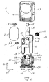
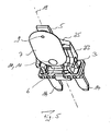
- the circuit breaker 1 comprises a housing 2 which is formed from a housing base 3 and a housing cover 4.
- the circuit breaker 1 further comprises a Fest.arm 5, a BimetallKINGarm 6 and a Bimetallschnappulation 7.
- the circuit breaker 1 also includes a fixed contact 8 in the form of a Welding plate, a moving contact 9 in the form of another welding plate and for fastening the Bimetallschnappulation 7 another rivet 10 and another welding plate 11th
- the housing base 3 and the housing cover 4 are made of electrical insulating material, namely a thermoplastic material.
- the one-piece housing cover 4 is pot-shaped or cap-shaped and thus encloses with five closed walls a volume which defines an interior 12 of the circuit breaker 1.
- the housing cover 4 can be snapped onto the housing base 3 with its open side.
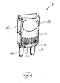
- Fig. 2 shows the circuit breaker 1 with the housing 2 closed, ie with attached to the housing base 3 housing cover 4th
- the contact arms 5 and 6 are bent-stamped parts made of sheet metal, in particular tinned brass, with a flat, rectangular cross-section.
- the housing base 3 of the Fest.arm 5 and the Bimetallkingarm 6 are positively embedded by the contact arms 5 and 6 are encapsulated with the material of the Gezzauesockels 3 in the manufacture of the circuit breaker 1.
- the contact arms 5 and 6 protrude on an underside 13 of the housing base 3, each with a plug contact 14 from the housing base 3 to the outside.
- the housing 2 and in particular the housing cover 4 have approximately the shape of a flat square with a (housing) narrow side 15 and a (housing) broadside 16.
- the contact arms 5 and 6 are embedded in the housing base 3 such that the plug contacts 14 are arranged parallel to each other and with respect to the housing narrow side 15 approximately centrally and at a distance from each other.
- the circuit breaker 1 is based on the standard ISO 8820 type F (miniature) with regard to its external geometric dimensions.
- the miniature circuit breaker 1 thus corresponds to the outside of a flat fuse of type F according to this standard, so that the circuit breaker 1 compatible with a socket for such Flachsteckêt, that is plugged into such, in the automotive field usual socket.
- the plug contacts 14 of the contact arms 5 and 6 are each arranged at the edge, while these are guided in the housing interior 12 respectively inwardly to the housing center, so that an inner end 17 of the Fest.arms 5 disposed over an inner end 18 of the Bimetallkingarms 6 is.
- top here - regardless of the actual orientation of the circuit breaker 1 in the room - the side facing away from the housing base 3 and the plug contacts 14 side of the circuit breaker 1 is designated.
- the inner ends 17 and 18 of the contact arms 5 and 6 are - as in particular from the Fig. 3 and 4 can be seen - in the direction of the housing broadside 16 centered with respect to a central longitudinal axis 19 ( Fig. 3 ) of the housing 2.
- the inner ends 17 and 18 of the contact arms 5 and 6 are bent in the direction of the narrow side 15 of the housing defined by the plug contacts 14 center plane of the circuit breaker 1 by offsets of the punched and bent parts and extend approximately parallel offset to the median plane or median longitudinal axis19.
- the inner end 17 of the Fest.arms 5 is in this case set back relative to the central plane (central longitudinal axis 19), while the inner end 18 of the Bimetalluttonarms 6 of the median plane (Mittelltulsachse19) is upstream.
- the longitudinal extension of the contact arms 5 and 6, and in particular of the plug contacts 14 of these contact arms 5 and 6, defines a longitudinal direction 20, while perpendicular thereto, the transverse direction 21 extends within the median plane.
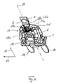
- the housing base 3 has in the transverse direction 21 extending a base 22 and two spaced apart in the longitudinal direction 20 extending base struts 23, 24 and another upper ends of these connecting, extending in the transverse direction 21 of the base traverse 25.
- the rivet 10 is fixed, on which the Bimetallschnappulation 7 is welded by means of the welding plate 11.
- this formed by the rivet and welding pads attachment point 10, 11 and thus aligned with this in the longitudinal direction 20 of the fixed contact 8 is welded to the Fest.
- a receiving pocket socket contour 27 is formed, which is in the assembled state in the longitudinal direction 20 between the attachment point 10, 11 and the fixed contact 8, and which is penetrated by the fixed contact 5 in the longitudinal direction 20 ( Fig. 3 ).
- two semi-circular base shells 27a and 27b are formed, wherein the distance - or the clear width - each other by the width of the Fest.arms 5 is determined.
- a compression spring 28 in the form of a conical spring referred to below as a conical spring with their base-side spring end 28 a.
- the conical spring 28 is thus positionally positioned in the housing base 3 and kept sufficient at least for a simplified and reliable.
- the crown-side spring end 28b of the conical spring 28 opposite the base-side spring end 28a protrudes in the in Fig. 3 shown partial assembly step into the interior 12 of the circuit breaker 1 inside. It shows Fig. 3 the relaxed state of the conical spring 28.
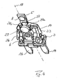
- Fig. 4 shows in a further partial assembly step, the use of a PTC resistor 29 - hereinafter simply referred to as resistance - within the circuit breaker 1 in the housing base 3.
- the resistor 29 is designed as a circular plate (resistance plate or resistance disc).
- the diameter of the plate-shaped or disc-shaped resistor 29 is in turn suitably adapted to the inner diameter (clear width) receiving pocket and is in this way again with compressed conical spring 28 due to the lateral boundary by means of the socket pockets 27a, 27b positionally accurate held in the housing base 3.
- Recognizable are in accordance with the Fig. 3 and 4 the conical spring 28 and the resistor 29 in the longitudinal direction 20 and preferably centered with the central axis 19 between the fixed contact 8 and serving in the installed state as a fixing point rivet 10 on the contact arm 6 in alignment.
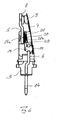
- the Fig. 5 to 7 shows the mounting state with arranged between the rivet 10 and the welding pad 11 bimetallic disc 7.
- the oval-shaped bimetal disc 7 is centered with respect to the longitudinal extent of the central axis 19 ( Fig. 5 ) and thus in the longitudinal direction 20 of the circuit breaker 1 and its contact arms 5 and 6 aligned.
- the held by means of the rivet 10 and the welding pad 11 on the contact arm 6 end of the Bimetallschnappulation 7 forms the attachment point 10, 11 on the corresponding contact arm 6, while the opposite free end of the Bimetallschnappulation 7 carries the moving contact 9 ( Fig. 6 and 7 ).
- the opposite free end of the Bimetallschnappulation 7 carries the moving contact 9 ( Fig. 6 and 7 ).
- the conical spring 28 and the PTC resistor 29 are located between the attachment point 10, 11 of the Bimetallschnappulation 7 and the contacts 8, 9. Visible, the PTC resistor 29 is flat and directly to the Bimetallschnappulation 7.
- the conical spring 28 rests with its base-side spring end 28a on the contact arm 5 of the fixed contact 8 and thereby in the receiving pocket 27 of the housing base 3 a. With the opposite vertex-side spring end 28b, the conical spring abuts the PTC resistor 29 as centrally as possible, where it forms a central tilting point 30.
- Bimetallschnappulation 7 In their normal position according to Fig. 6 in the longitudinal direction 20 obliquely extending Bimetallschnappulation 7 is the moving contact 9 under bias on the fixed contact 8 at an angle. As a result, an electrically conductive connection between the plug contacts 14 is made via the contact arms 5 and 6, the fixed contact 8, the moving contact 9 and the rivets 10. The circuit breaker 1 is thus electrically conductive in the normal state.
- the Bimetallschnappulation 7 is designed such that it changes its shape abruptly when its temperature exceeds a design predetermined default temperature, for example, 1700 ° C. As a result of this change in shape lifts the moving contact 9 from the fixed contact 8, so that the existing between the fixed contact 5 and the BimetallWalletarm 6 electrical connection is disconnected. Fig.
- a non-linear ceramic-type PTC resistor is used for the PTC resistor 29 . This heats up as a result of the current flow and limits the current to about 100mA. This corresponds to only about a third to a quarter of that current that is required in the known solutions.
- due to the non-linearity of the resistor 29 results in a relatively low relationship between the applied voltage and the power output. For the primary purpose in the electrical system of a motor vehicle, the output temperature and thus the power remain. over the entire usual voltage range of about 11V to 14.5V relatively constant. This is a particular advantage to which the benefit of reduced power output is added.
- a PTC resistor 29 is selected with a surface temperature of 275 ° C, which differs from the standard and appears for this type of PTC resistor as an upper limit.
- the surface temperature of such, used for heating PTC resistors is a maximum of 250 ° C. Since the PTC resistor 29 rests flatly and directly on the Bimetallschnappulation 7 and this is pressed for good heat transfer with a certain biasing force against the Bimetallschnappulation 7, both a particularly good heat transfer and a sufficient current flow through the PTC resistor 29 is possible.
- the PTC resistor 29 remains movable by the conical spring 28, the resistor 29 is not a large area, but in the region of the tilting point 30 and thus on the thereby small contact area rather in the middle Contacted area.
- the pressing force of the conical spring 28 is dimensioned such that the preferably disc-shaped PTC resistor 29 on the one hand rests well on the Bimetallschnappulation 7 and on the other hand does not adversely affect their snap behavior.
- the compression spring 28 is designed such that it can be compressed as completely as possible. In this way, the fact is taken into account that for positioning and placement of the compression spring 28 in the circuit breaker 1 and there between the Festuttonarm 5 and the Bimetallschnappulation 7 only very little space is available, which is also already partially required by the PTC resistor 29. Therefore, a compression spring 28 with conical spring body and thus in turn the use of a conical spring (cone spring) is particularly advantageous.
- the conical spring body is formed by continuously changing the coil diameter during winding of the spring wire.
- Such a preferred conical spring 28 is in Figure 8 shown.
- the turns or windings of the conical spring 28 are changed from turn to turn in spring longitudinal or axial direction, that the windings during compression of the conical spring 28 can slide into each other.
- the spring-free end 28c is suitably bent inwards on the base-side spring end 28a such that when the conical spring 28 is compressed, its spring height (block length) corresponds to practically only twice the spring wire thickness.
- the largest diameter D b of the conical spring 28 at its base-side spring end 28 a is approximately 4 mm and corresponds at least approximately to the diameter of the PTC resistor 29 with (4.2 ⁇ 0.1) mm.
- the conical spring 28 to toughen for automation of feeding the spring free end 28c of the base-side end of the spring - preferably in the plane of the last turn with the largest winding diameter D b - wound inward. This prevents that engage in an automatic feed the conical springs 28 with their small spring diameter D s in the large coil diameter D b another conical spring 28 and get caught there. In addition, it is achieved in this way that when completely compressed conical spring 28 only two spring coils lie on each other, which is advantageous for reasons of space.
- the thickness of the PTC resistor 29 is dimensioned such that it is both in the closed position of the circuit breaker 1 ( Fig. 6 ), as well as in the tripping or switch-off position of the bimetallic snap 7 ( Fig. 7 ) contacted, without slipping out of the lateral storage of the receiving pocket 27: It is considered by this constructive feature of providing the laterally supporting base shells 27a, 27b that due to different shaped Bimetallschnappulationn 7 at different currents different tolerances are expected.
- the structural design of the conical spring 28 also ensures that these also in the compressed state ( Fig. 6 ) does not go to block and thereby the PTC resistor 29 remains movable and does not affect the Bimetallschnappulation 7 in their snap behavior.
- a slice thickness of the PTC resistor 29 of (1.05 ⁇ 0.06) mm has been found to be optimal.
- the disk diameter of the PTC resistor 29 is preferably (4.2 ⁇ 0.1) mm.
- the invention accordingly relates to a miniature circuit breaker 1 for use in a motor vehicle electronics, with a housing base 3, from which a Fest.arm 5 and a BimetallWalletarm 6 attached thereto a moving contact 9 and a Bimetallschnappulation 7 are led out, wherein a PTC resistor 29 is brought by a compression spring 28 in direct contact with the Bimetallschnappulation 7 and electrically connected so that as a result of its heat generation Bimetallschnappulation 7 remains in the open position in the event of release.
Landscapes
- Physics & Mathematics (AREA)
- Thermal Sciences (AREA)
- Thermally Actuated Switches (AREA)
Priority Applications (1)
| Application Number | Priority Date | Filing Date | Title |
|---|---|---|---|
| PL11716828T PL2619784T3 (pl) | 2010-09-24 | 2011-04-12 | Miniaturowy wyłącznik ochronny |
Applications Claiming Priority (2)
| Application Number | Priority Date | Filing Date | Title |
|---|---|---|---|
| DE202010013526 | 2010-09-24 | ||
| PCT/EP2011/001809 WO2012037991A1 (de) | 2010-09-24 | 2011-04-12 | Miniatur-schutzschalter |
Publications (2)
| Publication Number | Publication Date |
|---|---|
| EP2619784A1 EP2619784A1 (de) | 2013-07-31 |
| EP2619784B1 true EP2619784B1 (de) | 2015-03-18 |
Family
ID=44477639
Family Applications (1)
| Application Number | Title | Priority Date | Filing Date |
|---|---|---|---|
| EP11716828.6A Active EP2619784B1 (de) | 2010-09-24 | 2011-04-12 | Miniatur-schutzschalter |
Country Status (12)
| Country | Link |
|---|---|
| US (2) | US10580600B2 (enExample) |
| EP (1) | EP2619784B1 (enExample) |
| JP (1) | JP5728092B2 (enExample) |
| KR (1) | KR101546277B1 (enExample) |
| CN (1) | CN103081051B (enExample) |
| CA (1) | CA2812451C (enExample) |
| DE (1) | DE202011110510U1 (enExample) |
| ES (1) | ES2536960T3 (enExample) |
| PL (1) | PL2619784T3 (enExample) |
| RU (1) | RU2553280C2 (enExample) |
| SG (1) | SG188299A1 (enExample) |
| WO (1) | WO2012037991A1 (enExample) |
Families Citing this family (15)
| Publication number | Priority date | Publication date | Assignee | Title |
|---|---|---|---|---|
| JP3089309B1 (ja) | 1999-04-07 | 2000-09-18 | 大蔵省印刷局長 | 粉体受入排出ホッパ及びそれを使用した粉体受入排出装置 |
| EP2770521B1 (en) * | 2013-02-20 | 2015-10-28 | Siemens Aktiengesellschaft | Thermo magnetic trip unit for a circuit breaker and circuit breaker |
| DE202014010782U1 (de) | 2014-03-21 | 2016-08-16 | Ellenberger & Poensgen Gmbh | Thermischer Schutzschalter |
| US10907638B2 (en) | 2015-07-27 | 2021-02-02 | Wayne/Scott Fetzer Company | Multi-outlet utility pump |
| USD823345S1 (en) | 2015-12-17 | 2018-07-17 | Wayne/Scott Fetzer Company | Pump |
| WO2017217003A1 (ja) * | 2016-06-14 | 2017-12-21 | 大塚テクノ株式会社 | 携帯機器用のマイクロブレーカ及び携帯機器用のマイクロブレーカの製造方法 |
| JP6967878B2 (ja) * | 2017-06-01 | 2021-11-17 | ボーンズ株式会社 | ブレーカー及びそれを備えた安全回路。 |
| US11326608B2 (en) * | 2017-08-14 | 2022-05-10 | Wayne/Scott Fetzer Company | Thermally controlled utility pump and methods relating to same |
| USD910719S1 (en) | 2018-07-12 | 2021-02-16 | Wayne/Scott Fetzer Company | Pump components |
| TWI785260B (zh) * | 2019-07-26 | 2022-12-01 | 富致科技股份有限公司 | 過電流保護裝置 |
| US10796872B1 (en) * | 2019-09-01 | 2020-10-06 | Kuoyuh W.L. Enterprise Co., Ltd. | Vehicle circuit breaker |
| CA3094775A1 (en) | 2019-09-30 | 2021-03-30 | Wayne/Scott Fetzer Company | Pump assembly and related methods |
| USD942512S1 (en) | 2020-09-29 | 2022-02-01 | Wayne/Scott Fetzer Company | Pump part |
| US12191098B2 (en) * | 2021-09-24 | 2025-01-07 | MP Hollywood | Switch with integral overcurrent protection |
| DE102022134379B3 (de) * | 2022-12-21 | 2024-02-08 | Marcel P. HOFSAESS | Temperaturabhängiger Schalter |
Family Cites Families (26)
| Publication number | Priority date | Publication date | Assignee | Title |
|---|---|---|---|---|
| US4363016A (en) | 1981-06-03 | 1982-12-07 | Amf Incorporated | Circuit breaker |
| DE3709660C2 (de) * | 1987-03-24 | 1994-11-24 | Ymos Ag Ind Produkte | Verschluß für ein Haushaltsgerät |
| US4808965A (en) * | 1987-11-06 | 1989-02-28 | Therm-O-Disc, Incorporated | Thermal protector |
| JP2779532B2 (ja) | 1989-12-28 | 1998-07-23 | 日本テキサス・インスツルメンツ株式会社 | 加熱装置 |
| DE59105486D1 (de) * | 1990-04-06 | 1995-06-22 | Ellenberger & Poensgen | Druckknopfbetätigter Schutzschalter. |
| GB9109316D0 (en) * | 1991-04-30 | 1991-06-19 | Otter Controls Ltd | Improvements relating to electric switches |
| RU2041573C1 (ru) * | 1992-06-15 | 1995-08-09 | Санкт-Петербургский производственный кооператив "Элав" | Способ защиты электронагревательного прибора от перегрева и устройство для его осуществления |
| DE4301958A1 (de) | 1992-08-11 | 1994-02-17 | Wilo Gmbh | Schutzeinrichtung für einen elektrischen Verbraucher |
| JP3692544B2 (ja) * | 1993-07-29 | 2005-09-07 | 株式会社村田製作所 | 自己保持型過電流保護装置 |
| JPH07282701A (ja) * | 1994-04-05 | 1995-10-27 | Texas Instr Japan Ltd | 自己保持型保護装置 |
| US5585774A (en) * | 1994-09-01 | 1996-12-17 | General Electric Company | Condition-responsive electric switch mechanism |
| GB2308510A (en) * | 1995-12-18 | 1997-06-25 | Huang Tse Chuan | Plug with safety cut-out switch |
| DE19705721B4 (de) * | 1997-02-14 | 2008-03-20 | Behr Thermot-Tronik Gmbh | Stellantrieb mit einem elektrisch beheizbaren thermostatischen Arbeitselement |
| DE19807288C2 (de) * | 1998-02-23 | 2001-09-20 | Marcel Hofsaes | Temperaturabhängiger Schalter |
| US6191680B1 (en) * | 1998-02-23 | 2001-02-20 | HOFSäSS MARCEL | Switch having a safety element |
| JPH11273519A (ja) | 1998-03-25 | 1999-10-08 | Hosiden Corp | サーキットプロテクタとそれに用いる弾性熱応動板の製法 |
| DE19852578C5 (de) * | 1998-11-04 | 2005-11-17 | Ellenberger & Poensgen Gmbh | Verriegelungsvorrichtung z. B. für Hausgerätetüren |
| DE19856707A1 (de) | 1998-12-09 | 2000-06-21 | Ellenberger & Poensgen | Schutzschalter zur Absicherung von Stromkreisen |
| JP3756700B2 (ja) * | 1999-07-22 | 2006-03-15 | ウチヤ・サーモスタット株式会社 | サーマルプロテクタ |
| JP2004014434A (ja) * | 2002-06-11 | 2004-01-15 | Uchiya Thermostat Kk | 直流電流遮断スイッチ |
| DE10236777A1 (de) * | 2002-08-10 | 2004-03-04 | Ellenberger & Poensgen Gmbh | Elektrothermisch gesteuerte Verriegelungsvorrichtung für eine Gerätetür |
| US7102481B2 (en) * | 2003-12-03 | 2006-09-05 | Sensata Technologies, Inc. | Low current electric motor protector |
| DE102007038641A1 (de) * | 2007-08-16 | 2009-02-26 | Möhlenhoff Wärmetechnik GmbH | Anordnung zum Verstellen eines Ventils |
| DE202009010473U1 (de) * | 2008-09-29 | 2010-02-25 | Ellenberger & Poensgen Gmbh | Miniatur-Schutzschalter |
| DE102008049507A1 (de) | 2008-09-29 | 2010-04-01 | Ellenberger & Poensgen Gmbh | Miniatur-Schutzschalter |
| US7808361B1 (en) * | 2008-11-25 | 2010-10-05 | Tsung Mou Yu | Dual protection device for circuit |
-
2011
- 2011-04-12 CN CN201180041153.5A patent/CN103081051B/zh active Active
- 2011-04-12 KR KR1020137010229A patent/KR101546277B1/ko active Active
- 2011-04-12 WO PCT/EP2011/001809 patent/WO2012037991A1/de not_active Ceased
- 2011-04-12 RU RU2013118692/07A patent/RU2553280C2/ru active
- 2011-04-12 PL PL11716828T patent/PL2619784T3/pl unknown
- 2011-04-12 SG SG2013014030A patent/SG188299A1/en unknown
- 2011-04-12 CA CA2812451A patent/CA2812451C/en active Active
- 2011-04-12 ES ES11716828.6T patent/ES2536960T3/es active Active
- 2011-04-12 DE DE202011110510.9U patent/DE202011110510U1/de not_active Expired - Lifetime
- 2011-04-12 EP EP11716828.6A patent/EP2619784B1/de active Active
- 2011-04-12 JP JP2013529556A patent/JP5728092B2/ja active Active
-
2013
- 2013-03-25 US US13/849,745 patent/US10580600B2/en active Active
-
2018
- 2018-10-03 US US16/150,770 patent/US10600597B2/en active Active
Also Published As
| Publication number | Publication date |
|---|---|
| RU2553280C2 (ru) | 2015-06-10 |
| CN103081051B (zh) | 2015-12-16 |
| JP5728092B2 (ja) | 2015-06-03 |
| CN103081051A (zh) | 2013-05-01 |
| US10600597B2 (en) | 2020-03-24 |
| WO2012037991A1 (de) | 2012-03-29 |
| EP2619784A1 (de) | 2013-07-31 |
| KR20130103536A (ko) | 2013-09-23 |
| RU2013118692A (ru) | 2014-10-27 |
| PL2619784T3 (pl) | 2015-08-31 |
| CA2812451A1 (en) | 2012-03-29 |
| US10580600B2 (en) | 2020-03-03 |
| SG188299A1 (en) | 2013-04-30 |
| CA2812451C (en) | 2019-01-15 |
| ES2536960T3 (es) | 2015-06-01 |
| JP2013538004A (ja) | 2013-10-07 |
| US20190035582A1 (en) | 2019-01-31 |
| KR101546277B1 (ko) | 2015-08-21 |
| US20130214895A1 (en) | 2013-08-22 |
| DE202011110510U1 (de) | 2014-05-27 |
Similar Documents
| Publication | Publication Date | Title |
|---|---|---|
| EP2619784B1 (de) | Miniatur-schutzschalter | |
| DE3688800T2 (de) | Schutzsysteme für einen Kältemaschinenkompressormotor. | |
| EP2874171B1 (de) | Temperaturabhängiges schaltwerk | |
| DE102013102006B4 (de) | Temperaturabhängiger Schalter | |
| DE102011101862B4 (de) | Temperaturabhängiger Schalter mit Stromübertragungsglied | |
| DE102011016896B3 (de) | Temperaturschutzschalter | |
| EP0756301B1 (de) | Temperaturwächter | |
| DE102011119632B3 (de) | Temperaturabhängiges Schaltwerk | |
| DE102011119637B4 (de) | Temperaturabhängiger Schalter mit einem temperaturabhängigen Schaltwerk sowie Verfahren zum Herstellen eines solchen Schalters | |
| DE69414400T2 (de) | Elektrische schalter | |
| EP2304757A1 (de) | Bimetallteil und damit ausgestattete temperaturabhängige schalter | |
| EP0740323B1 (de) | Temperaturwächter mit einem bei Übertemperatur schaltenden Bimetall-Schaltwerk | |
| EP0938117B1 (de) | Schalter | |
| DE8904063U1 (de) | Druckknopfbetätigter Überstromschutzschalter | |
| EP2779196B1 (de) | Miniatur-Schutzschalter | |
| EP2038905A1 (de) | Anschlussübertopf und schalter mit anschlussübertopf | |
| DE2511214C2 (de) | Temperaturregeleinrichtung für elektrische Geräte | |
| DE202009010473U1 (de) | Miniatur-Schutzschalter | |
| DE1200414B (de) | Bimetallschaltvorrichtung | |
| DE102022134379B3 (de) | Temperaturabhängiger Schalter | |
| DE102023104839B3 (de) | Temperaturabhängiger Schalter | |
| EP0162940A1 (de) | Überlastsicherungsschalter | |
| DE4029527A1 (de) | Thermoschalter mit bimetall-schnappscheibe | |
| DE2811441C2 (de) | Niederspannungsschutzschalter mit Kompensationsbimetall | |
| EP4528772A2 (de) | Temperaturabhängiges schaltwerk und temperaturabhängiger schalter |
Legal Events
| Date | Code | Title | Description |
|---|---|---|---|
| PUAI | Public reference made under article 153(3) epc to a published international application that has entered the european phase |
Free format text: ORIGINAL CODE: 0009012 |
|
| 17P | Request for examination filed |
Effective date: 20130205 |
|
| AK | Designated contracting states |
Kind code of ref document: A1 Designated state(s): AL AT BE BG CH CY CZ DE DK EE ES FI FR GB GR HR HU IE IS IT LI LT LU LV MC MK MT NL NO PL PT RO RS SE SI SK SM TR |
|
| DAX | Request for extension of the european patent (deleted) | ||
| GRAP | Despatch of communication of intention to grant a patent |
Free format text: ORIGINAL CODE: EPIDOSNIGR1 |
|
| INTG | Intention to grant announced |
Effective date: 20140905 |
|
| GRAS | Grant fee paid |
Free format text: ORIGINAL CODE: EPIDOSNIGR3 |
|
| GRAP | Despatch of communication of intention to grant a patent |
Free format text: ORIGINAL CODE: EPIDOSNIGR1 |
|
| GRAA | (expected) grant |
Free format text: ORIGINAL CODE: 0009210 |
|
| INTG | Intention to grant announced |
Effective date: 20150130 |
|
| AK | Designated contracting states |
Kind code of ref document: B1 Designated state(s): AL AT BE BG CH CY CZ DE DK EE ES FI FR GB GR HR HU IE IS IT LI LT LU LV MC MK MT NL NO PL PT RO RS SE SI SK SM TR |
|
| REG | Reference to a national code |
Ref country code: GB Ref legal event code: FG4D Free format text: NOT ENGLISH |
|
| REG | Reference to a national code |
Ref country code: CH Ref legal event code: EP |
|
| REG | Reference to a national code |
Ref country code: IE Ref legal event code: FG4D Free format text: LANGUAGE OF EP DOCUMENT: GERMAN |
|
| REG | Reference to a national code |
Ref country code: AT Ref legal event code: REF Ref document number: 717036 Country of ref document: AT Kind code of ref document: T Effective date: 20150415 |
|
| REG | Reference to a national code |
Ref country code: DE Ref legal event code: R096 Ref document number: 502011006298 Country of ref document: DE Effective date: 20150430 Ref country code: CH Ref legal event code: NV Representative=s name: E. BLUM AND CO. AG PATENT- UND MARKENANWAELTE , CH |
|
| REG | Reference to a national code |
Ref country code: ES Ref legal event code: FG2A Ref document number: 2536960 Country of ref document: ES Kind code of ref document: T3 Effective date: 20150601 |
|
| REG | Reference to a national code |
Ref country code: SE Ref legal event code: TRGR |
|
| REG | Reference to a national code |
Ref country code: NL Ref legal event code: T3 |
|
| PG25 | Lapsed in a contracting state [announced via postgrant information from national office to epo] |
Ref country code: LT Free format text: LAPSE BECAUSE OF FAILURE TO SUBMIT A TRANSLATION OF THE DESCRIPTION OR TO PAY THE FEE WITHIN THE PRESCRIBED TIME-LIMIT Effective date: 20150318 Ref country code: HR Free format text: LAPSE BECAUSE OF FAILURE TO SUBMIT A TRANSLATION OF THE DESCRIPTION OR TO PAY THE FEE WITHIN THE PRESCRIBED TIME-LIMIT Effective date: 20150318 Ref country code: NO Free format text: LAPSE BECAUSE OF FAILURE TO SUBMIT A TRANSLATION OF THE DESCRIPTION OR TO PAY THE FEE WITHIN THE PRESCRIBED TIME-LIMIT Effective date: 20150618 |
|
| PGFP | Annual fee paid to national office [announced via postgrant information from national office to epo] |
Ref country code: CH Payment date: 20150430 Year of fee payment: 5 Ref country code: FI Payment date: 20150629 Year of fee payment: 5 |
|
| REG | Reference to a national code |
Ref country code: LT Ref legal event code: MG4D |
|
| PG25 | Lapsed in a contracting state [announced via postgrant information from national office to epo] |
Ref country code: LV Free format text: LAPSE BECAUSE OF FAILURE TO SUBMIT A TRANSLATION OF THE DESCRIPTION OR TO PAY THE FEE WITHIN THE PRESCRIBED TIME-LIMIT Effective date: 20150318 Ref country code: RS Free format text: LAPSE BECAUSE OF FAILURE TO SUBMIT A TRANSLATION OF THE DESCRIPTION OR TO PAY THE FEE WITHIN THE PRESCRIBED TIME-LIMIT Effective date: 20150318 Ref country code: GR Free format text: LAPSE BECAUSE OF FAILURE TO SUBMIT A TRANSLATION OF THE DESCRIPTION OR TO PAY THE FEE WITHIN THE PRESCRIBED TIME-LIMIT Effective date: 20150619 |
|
| REG | Reference to a national code |
Ref country code: PL Ref legal event code: T3 |
|
| PG25 | Lapsed in a contracting state [announced via postgrant information from national office to epo] |
Ref country code: PT Free format text: LAPSE BECAUSE OF FAILURE TO SUBMIT A TRANSLATION OF THE DESCRIPTION OR TO PAY THE FEE WITHIN THE PRESCRIBED TIME-LIMIT Effective date: 20150720 Ref country code: EE Free format text: LAPSE BECAUSE OF FAILURE TO SUBMIT A TRANSLATION OF THE DESCRIPTION OR TO PAY THE FEE WITHIN THE PRESCRIBED TIME-LIMIT Effective date: 20150318 Ref country code: SK Free format text: LAPSE BECAUSE OF FAILURE TO SUBMIT A TRANSLATION OF THE DESCRIPTION OR TO PAY THE FEE WITHIN THE PRESCRIBED TIME-LIMIT Effective date: 20150318 Ref country code: RO Free format text: LAPSE BECAUSE OF FAILURE TO SUBMIT A TRANSLATION OF THE DESCRIPTION OR TO PAY THE FEE WITHIN THE PRESCRIBED TIME-LIMIT Effective date: 20150318 |
|
| PG25 | Lapsed in a contracting state [announced via postgrant information from national office to epo] |
Ref country code: IS Free format text: LAPSE BECAUSE OF FAILURE TO SUBMIT A TRANSLATION OF THE DESCRIPTION OR TO PAY THE FEE WITHIN THE PRESCRIBED TIME-LIMIT Effective date: 20150718 Ref country code: MC Free format text: LAPSE BECAUSE OF FAILURE TO SUBMIT A TRANSLATION OF THE DESCRIPTION OR TO PAY THE FEE WITHIN THE PRESCRIBED TIME-LIMIT Effective date: 20150318 |
|
| REG | Reference to a national code |
Ref country code: DE Ref legal event code: R097 Ref document number: 502011006298 Country of ref document: DE |
|
| PLBE | No opposition filed within time limit |
Free format text: ORIGINAL CODE: 0009261 |
|
| STAA | Information on the status of an ep patent application or granted ep patent |
Free format text: STATUS: NO OPPOSITION FILED WITHIN TIME LIMIT |
|
| REG | Reference to a national code |
Ref country code: IE Ref legal event code: MM4A |
|
| PG25 | Lapsed in a contracting state [announced via postgrant information from national office to epo] |
Ref country code: DK Free format text: LAPSE BECAUSE OF FAILURE TO SUBMIT A TRANSLATION OF THE DESCRIPTION OR TO PAY THE FEE WITHIN THE PRESCRIBED TIME-LIMIT Effective date: 20150318 |
|
| 26N | No opposition filed |
Effective date: 20151221 |
|
| PG25 | Lapsed in a contracting state [announced via postgrant information from national office to epo] |
Ref country code: SI Free format text: LAPSE BECAUSE OF FAILURE TO SUBMIT A TRANSLATION OF THE DESCRIPTION OR TO PAY THE FEE WITHIN THE PRESCRIBED TIME-LIMIT Effective date: 20150318 |
|
| REG | Reference to a national code |
Ref country code: FR Ref legal event code: PLFP Year of fee payment: 6 |
|
| PG25 | Lapsed in a contracting state [announced via postgrant information from national office to epo] |
Ref country code: IE Free format text: LAPSE BECAUSE OF NON-PAYMENT OF DUE FEES Effective date: 20150412 |
|
| REG | Reference to a national code |
Ref country code: CH Ref legal event code: PL |
|
| PG25 | Lapsed in a contracting state [announced via postgrant information from national office to epo] |
Ref country code: MT Free format text: LAPSE BECAUSE OF FAILURE TO SUBMIT A TRANSLATION OF THE DESCRIPTION OR TO PAY THE FEE WITHIN THE PRESCRIBED TIME-LIMIT Effective date: 20150318 |
|
| PG25 | Lapsed in a contracting state [announced via postgrant information from national office to epo] |
Ref country code: CH Free format text: LAPSE BECAUSE OF NON-PAYMENT OF DUE FEES Effective date: 20160430 Ref country code: FI Free format text: LAPSE BECAUSE OF NON-PAYMENT OF DUE FEES Effective date: 20160412 Ref country code: LI Free format text: LAPSE BECAUSE OF NON-PAYMENT OF DUE FEES Effective date: 20160430 |
|
| REG | Reference to a national code |
Ref country code: FR Ref legal event code: PLFP Year of fee payment: 7 |
|
| PG25 | Lapsed in a contracting state [announced via postgrant information from national office to epo] |
Ref country code: SM Free format text: LAPSE BECAUSE OF FAILURE TO SUBMIT A TRANSLATION OF THE DESCRIPTION OR TO PAY THE FEE WITHIN THE PRESCRIBED TIME-LIMIT Effective date: 20150318 Ref country code: HU Free format text: LAPSE BECAUSE OF FAILURE TO SUBMIT A TRANSLATION OF THE DESCRIPTION OR TO PAY THE FEE WITHIN THE PRESCRIBED TIME-LIMIT; INVALID AB INITIO Effective date: 20110412 Ref country code: BG Free format text: LAPSE BECAUSE OF FAILURE TO SUBMIT A TRANSLATION OF THE DESCRIPTION OR TO PAY THE FEE WITHIN THE PRESCRIBED TIME-LIMIT Effective date: 20150318 |
|
| PG25 | Lapsed in a contracting state [announced via postgrant information from national office to epo] |
Ref country code: CY Free format text: LAPSE BECAUSE OF FAILURE TO SUBMIT A TRANSLATION OF THE DESCRIPTION OR TO PAY THE FEE WITHIN THE PRESCRIBED TIME-LIMIT Effective date: 20150318 |
|
| PG25 | Lapsed in a contracting state [announced via postgrant information from national office to epo] |
Ref country code: LU Free format text: LAPSE BECAUSE OF NON-PAYMENT OF DUE FEES Effective date: 20150412 |
|
| REG | Reference to a national code |
Ref country code: FR Ref legal event code: PLFP Year of fee payment: 8 |
|
| PG25 | Lapsed in a contracting state [announced via postgrant information from national office to epo] |
Ref country code: MK Free format text: LAPSE BECAUSE OF FAILURE TO SUBMIT A TRANSLATION OF THE DESCRIPTION OR TO PAY THE FEE WITHIN THE PRESCRIBED TIME-LIMIT Effective date: 20150318 |
|
| PG25 | Lapsed in a contracting state [announced via postgrant information from national office to epo] |
Ref country code: AL Free format text: LAPSE BECAUSE OF FAILURE TO SUBMIT A TRANSLATION OF THE DESCRIPTION OR TO PAY THE FEE WITHIN THE PRESCRIBED TIME-LIMIT Effective date: 20150318 |
|
| P01 | Opt-out of the competence of the unified patent court (upc) registered |
Effective date: 20231120 |
|
| PGFP | Annual fee paid to national office [announced via postgrant information from national office to epo] |
Ref country code: TR Payment date: 20240401 Year of fee payment: 14 |
|
| PGFP | Annual fee paid to national office [announced via postgrant information from national office to epo] |
Ref country code: NL Payment date: 20250422 Year of fee payment: 15 |
|
| PGFP | Annual fee paid to national office [announced via postgrant information from national office to epo] |
Ref country code: DE Payment date: 20250429 Year of fee payment: 15 |
|
| PGFP | Annual fee paid to national office [announced via postgrant information from national office to epo] |
Ref country code: ES Payment date: 20250519 Year of fee payment: 15 |
|
| PGFP | Annual fee paid to national office [announced via postgrant information from national office to epo] |
Ref country code: BE Payment date: 20250422 Year of fee payment: 15 Ref country code: IT Payment date: 20250430 Year of fee payment: 15 |
|
| PGFP | Annual fee paid to national office [announced via postgrant information from national office to epo] |
Ref country code: FR Payment date: 20250428 Year of fee payment: 15 |
|
| PGFP | Annual fee paid to national office [announced via postgrant information from national office to epo] |
Ref country code: AT Payment date: 20250416 Year of fee payment: 15 |
|
| PGFP | Annual fee paid to national office [announced via postgrant information from national office to epo] |
Ref country code: SE Payment date: 20250423 Year of fee payment: 15 |
|
| PGFP | Annual fee paid to national office [announced via postgrant information from national office to epo] |
Ref country code: GB Payment date: 20260324 Year of fee payment: 16 |
|
| PGFP | Annual fee paid to national office [announced via postgrant information from national office to epo] |
Ref country code: CZ Payment date: 20260327 Year of fee payment: 16 |
|
| PGFP | Annual fee paid to national office [announced via postgrant information from national office to epo] |
Ref country code: PL Payment date: 20260331 Year of fee payment: 16 |