JP5728092B2 - 小型安全スイッチ - Google Patents
小型安全スイッチ Download PDFInfo
- Publication number
- JP5728092B2 JP5728092B2 JP2013529556A JP2013529556A JP5728092B2 JP 5728092 B2 JP5728092 B2 JP 5728092B2 JP 2013529556 A JP2013529556 A JP 2013529556A JP 2013529556 A JP2013529556 A JP 2013529556A JP 5728092 B2 JP5728092 B2 JP 5728092B2
- Authority
- JP
- Japan
- Prior art keywords
- safety switch
- contact
- ptc resistor
- base
- spring
- Prior art date
- Legal status (The legal status is an assumption and is not a legal conclusion. Google has not performed a legal analysis and makes no representation as to the accuracy of the status listed.)
- Active
Links
- 230000006835 compression Effects 0.000 claims description 33
- 238000007906 compression Methods 0.000 claims description 33
- 230000001960 triggered effect Effects 0.000 claims description 11
- 239000011810 insulating material Substances 0.000 claims 1
- 238000004804 winding Methods 0.000 description 7
- 238000010438 heat treatment Methods 0.000 description 5
- 238000003466 welding Methods 0.000 description 5
- 238000004519 manufacturing process Methods 0.000 description 3
- 239000000463 material Substances 0.000 description 3
- 239000002184 metal Substances 0.000 description 2
- 229910001369 Brass Inorganic materials 0.000 description 1
- 230000002411 adverse Effects 0.000 description 1
- 238000005452 bending Methods 0.000 description 1
- 239000010951 brass Substances 0.000 description 1
- 239000000919 ceramic Substances 0.000 description 1
- 239000011248 coating agent Substances 0.000 description 1
- 238000000576 coating method Methods 0.000 description 1
- 238000010276 construction Methods 0.000 description 1
- 238000001816 cooling Methods 0.000 description 1
- 238000010586 diagram Methods 0.000 description 1
- 238000010292 electrical insulation Methods 0.000 description 1
- 239000012777 electrically insulating material Substances 0.000 description 1
- 238000005516 engineering process Methods 0.000 description 1
- 239000003365 glass fiber Substances 0.000 description 1
- 230000020169 heat generation Effects 0.000 description 1
- 238000003780 insertion Methods 0.000 description 1
- 230000037431 insertion Effects 0.000 description 1
- 238000009413 insulation Methods 0.000 description 1
- 238000000034 method Methods 0.000 description 1
- 239000004033 plastic Substances 0.000 description 1
- 229920003223 poly(pyromellitimide-1,4-diphenyl ether) Polymers 0.000 description 1
- 238000003825 pressing Methods 0.000 description 1
- 230000000717 retained effect Effects 0.000 description 1
- 230000002441 reversible effect Effects 0.000 description 1
- 229910000679 solder Inorganic materials 0.000 description 1
- 229920001169 thermoplastic Polymers 0.000 description 1
- 239000004416 thermosoftening plastic Substances 0.000 description 1
Images


Classifications
-
- H—ELECTRICITY
- H01—ELECTRIC ELEMENTS
- H01H—ELECTRIC SWITCHES; RELAYS; SELECTORS; EMERGENCY PROTECTIVE DEVICES
- H01H37/00—Thermally-actuated switches
- H01H37/02—Details
- H01H37/32—Thermally-sensitive members
- H01H37/52—Thermally-sensitive members actuated due to deflection of bimetallic element
- H01H37/54—Thermally-sensitive members actuated due to deflection of bimetallic element wherein the bimetallic element is inherently snap acting
-
- H—ELECTRICITY
- H01—ELECTRIC ELEMENTS
- H01H—ELECTRIC SWITCHES; RELAYS; SELECTORS; EMERGENCY PROTECTIVE DEVICES
- H01H37/00—Thermally-actuated switches
- H01H37/02—Details
- H01H37/60—Means for producing snap action
-
- H—ELECTRICITY
- H01—ELECTRIC ELEMENTS
- H01H—ELECTRIC SWITCHES; RELAYS; SELECTORS; EMERGENCY PROTECTIVE DEVICES
- H01H37/00—Thermally-actuated switches
- H01H37/02—Details
- H01H37/32—Thermally-sensitive members
- H01H37/52—Thermally-sensitive members actuated due to deflection of bimetallic element
- H01H37/54—Thermally-sensitive members actuated due to deflection of bimetallic element wherein the bimetallic element is inherently snap acting
- H01H37/5409—Bistable switches; Resetting means
-
- H—ELECTRICITY
- H01—ELECTRIC ELEMENTS
- H01H—ELECTRIC SWITCHES; RELAYS; SELECTORS; EMERGENCY PROTECTIVE DEVICES
- H01H71/00—Details of the protective switches or relays covered by groups H01H73/00 - H01H83/00
- H01H71/10—Operating or release mechanisms
- H01H71/12—Automatic release mechanisms with or without manual release
- H01H71/14—Electrothermal mechanisms
- H01H71/16—Electrothermal mechanisms with bimetal element
- H01H71/164—Heating elements
-
- H—ELECTRICITY
- H01—ELECTRIC ELEMENTS
- H01H—ELECTRIC SWITCHES; RELAYS; SELECTORS; EMERGENCY PROTECTIVE DEVICES
- H01H37/00—Thermally-actuated switches
- H01H37/02—Details
- H01H37/32—Thermally-sensitive members
- H01H37/52—Thermally-sensitive members actuated due to deflection of bimetallic element
- H01H37/54—Thermally-sensitive members actuated due to deflection of bimetallic element wherein the bimetallic element is inherently snap acting
- H01H2037/5463—Thermally-sensitive members actuated due to deflection of bimetallic element wherein the bimetallic element is inherently snap acting the bimetallic snap element forming part of switched circuit
Landscapes
- Physics & Mathematics (AREA)
- Thermal Sciences (AREA)
- Thermally Actuated Switches (AREA)
Description
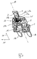
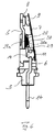
組立状態では、以降で略して円錐コイルばねと呼ぶ円錐台状コイルばねの形態の圧縮ばね28が、その基部側ばね端部28aを介して受入ポケット27内に位置している。横方向21において基部殻状部27aおよび27bによって横方向が画定されている受入ポケット27の自由断面積は、円錐コイルばね28の基部側ばね端部28aの比較的大きいばね直径に適合させてある。したがって、円錐コイルばね28は、ハウジング基部3内に位置決めして設置され、少なくとも簡略化されかつ確実な方法で十分に保持される。基部側ばね端部28aとは反対側の円錐コイルばね28の頂点側ばね端部28bは、図3に示す半組立ステップにおいて安全スイッチ1の内部12に突出している。図3は、円錐コイルばね28の伸展状態を示す。
2 ハウジング
3 ハウジング基部
4 ハウジングカバー/キャップ
5 固定接点アーム
6 バイメタル接点アーム
7 バイメタルスナップディスク
8 固定接点
9 可動接点
10 リベット
11 溶接プレート
12 内部
13 下側
14 差込み接点
15 ハウジング幅狭面
16 ハウジング幅広面
17 固定接点アームの内側端部
18 バイメタル接点アームの内側端部
19 中心長手方向軸
20 長手方向
21 横方向
22 基部
23、24 基部支柱
25 基部桁部材
26 基部空洞
27 受入ポケット
27a、27b 基部殻状部
28 円錐コイルばね
28a 基部側ばね端部/コイル
28b 頂点側ばね端部/コイル
28c ばね自由端
29 PTC抵抗器
30 傾斜転換ポイント
Db 基部側ばね/コイル径
Ds 頂点側ばね/コイル径
Claims (10)
- 自動車電子機器に使用される小型安全スイッチ(1)であって、
絶縁材料によるハウジング基部(3)およびこれに取り付けることができるかまたは取り付けられているハウジングカバー(4)から形成されるハウジング(2)と、
長手方向(20)において互いに平行に前記ハウジング基部(3)に組み込まれ、基部側において前記ハウジング基部(3)から引き出されている、それぞれが細長い平坦な第1接点アーム(5)及び第2接点アーム(6)と、
前記ハウジング内で、前記第1接点アーム(5)に取り付けられた固定接点(8)および前記第2接点アーム(6)に取り付けられた、可動接点(9)を有するバイメタルスナップディスク(7)と、
当該PTC抵抗器によって熱が発生する結果、前記バイメタルスナップディスク(7)がトリガ時に開位置を維持するように、電気的に組み込まれているPTC抵抗器(29)と、
を備え、
前記PTC抵抗器(29)が、圧縮ばね(28)によって前記バイメタルスナップディスク(7)と直接接触させられ、該圧縮ばね(28)が、前記長手方向(20)において前記固定接点(8)よりも下の方で前記第1接点アーム(5)に支持されていることを特徴とする、小型安全スイッチ。 - 前記圧縮ばね(28)が円錐コイルばねであり、該円錐コイルばねの基部側ばね端部(28a)が前記第1接点アーム(5)と接触し、前記円錐コイルばねの頂点側ばね端部(28b)が前記PTC抵抗器(29)と接触することを特徴とする請求項1に記載の小型安全スイッチ。
- 前記圧縮ばね(28)の直径(Db,Ds)が、前記基部側ばね端部(28a)において4mmであり、前記頂点側ばね端部(28b)において2mmであることを特徴とする請求項2に記載の小型安全スイッチ。
- 前記PCT抵抗器(29)がディスク状であって、そのディスク径が、前記圧縮ばね(28)の前記基部側ばね端部(28a)における前記直径(Db)に対応することを特徴とする請求項2または請求項3に記載の小型安全スイッチ。
- 前記PTC抵抗器(29)のディスク径が(4.2±0.1)mmであり、前記PTC抵抗器(29)のディスク厚さが(1.05±0.06)mmであることを特徴とする請求項4に記載の小型安全スイッチ。
- 前記圧縮ばね(28)の前記頂点側ばね端部(28b)が、前記ディスク状のPTC抵抗器(29)の中心部分で接触することを特徴とする請求項4または請求項5に記載の小型安全スイッチ。
- 前記固定接点(8)を保持する前記第1接点アーム(5)が、該第1接点アーム(5)に対して横方向(21)に伸びるハウジング横材(25)のポケット状基部輪郭部(27)を通して導かれ、
前記圧縮ばね(28)は、前記PTC抵抗器(29)とは反対側の前記ばね端部(28a)が前記基部輪郭部(27)内に挿入され、これにより少なくとも横方向に支持されていることを特徴とする請求項1〜6のいずれか1項に記載の小型安全スイッチ。 - 前記バイメタルスナップディスク(7)が、前記第2接点アーム(6)に固定箇所(10,11)において取り付けられ、
前記PTC抵抗器(29)が、前記長手方向(20)において、前記固定箇所(10,11)と前記可動接点または前記固定接点(8,9)との間に配置されていることを特徴とする請求項1〜7のいずれか1項に記載の小型安全スイッチ。 - 前記PTC抵抗器(29)が、前記バイメタルスナップディスク(7)の中央で該バイメタルスナップディスク(7)と接触することを特徴とする請求項1〜8のいずれか1項に記載の小型安全スイッチ。
- 前記PTC抵抗器(29)が、前記圧縮ばね(28)を介して前記第1接点アーム(5)と、前記バイメタルスナップディスク(7)を介して前記第2接点アーム(6)と電気的に接触することにより、トリガ時に前記PTC抵抗器(29)に電流が流れ、当該PTC抵抗器が発熱することを特徴とする請求項1〜9のいずれか1項に記載の小型安全スイッチ。
Applications Claiming Priority (3)
| Application Number | Priority Date | Filing Date | Title |
|---|---|---|---|
| DE202010013526 | 2010-09-24 | ||
| DE202010013526.5 | 2010-09-24 | ||
| PCT/EP2011/001809 WO2012037991A1 (de) | 2010-09-24 | 2011-04-12 | Miniatur-schutzschalter |
Publications (3)
| Publication Number | Publication Date |
|---|---|
| JP2013538004A JP2013538004A (ja) | 2013-10-07 |
| JP2013538004A5 JP2013538004A5 (ja) | 2014-03-20 |
| JP5728092B2 true JP5728092B2 (ja) | 2015-06-03 |
Family
ID=44477639
Family Applications (1)
| Application Number | Title | Priority Date | Filing Date |
|---|---|---|---|
| JP2013529556A Active JP5728092B2 (ja) | 2010-09-24 | 2011-04-12 | 小型安全スイッチ |
Country Status (12)
| Country | Link |
|---|---|
| US (2) | US10580600B2 (ja) |
| EP (1) | EP2619784B1 (ja) |
| JP (1) | JP5728092B2 (ja) |
| KR (1) | KR101546277B1 (ja) |
| CN (1) | CN103081051B (ja) |
| CA (1) | CA2812451C (ja) |
| DE (1) | DE202011110510U1 (ja) |
| ES (1) | ES2536960T3 (ja) |
| PL (1) | PL2619784T3 (ja) |
| RU (1) | RU2553280C2 (ja) |
| SG (1) | SG188299A1 (ja) |
| WO (1) | WO2012037991A1 (ja) |
Families Citing this family (12)
| Publication number | Priority date | Publication date | Assignee | Title |
|---|---|---|---|---|
| EP2770521B1 (en) * | 2013-02-20 | 2015-10-28 | Siemens Aktiengesellschaft | Thermo magnetic trip unit for a circuit breaker and circuit breaker |
| DE202014010782U1 (de) | 2014-03-21 | 2016-08-16 | Ellenberger & Poensgen Gmbh | Thermischer Schutzschalter |
| US10907638B2 (en) | 2015-07-27 | 2021-02-02 | Wayne/Scott Fetzer Company | Multi-outlet utility pump |
| USD823345S1 (en) | 2015-12-17 | 2018-07-17 | Wayne/Scott Fetzer Company | Pump |
| JP6918298B2 (ja) * | 2016-06-14 | 2021-08-11 | 大塚テクノ株式会社 | 携帯機器用のマイクロブレーカ及び携帯機器用のマイクロブレーカの製造方法 |
| JP6967878B2 (ja) * | 2017-06-01 | 2021-11-17 | ボーンズ株式会社 | ブレーカー及びそれを備えた安全回路。 |
| US11326608B2 (en) * | 2017-08-14 | 2022-05-10 | Wayne/Scott Fetzer Company | Thermally controlled utility pump and methods relating to same |
| USD910719S1 (en) | 2018-07-12 | 2021-02-16 | Wayne/Scott Fetzer Company | Pump components |
| TWI785260B (zh) * | 2019-07-26 | 2022-12-01 | 富致科技股份有限公司 | 過電流保護裝置 |
| US10796872B1 (en) * | 2019-09-01 | 2020-10-06 | Kuoyuh W.L. Enterprise Co., Ltd. | Vehicle circuit breaker |
| US11592033B2 (en) | 2019-09-30 | 2023-02-28 | Wayne/Scott Fetzer Company | Pump assembly and related methods |
| USD942512S1 (en) | 2020-09-29 | 2022-02-01 | Wayne/Scott Fetzer Company | Pump part |
Family Cites Families (26)
| Publication number | Priority date | Publication date | Assignee | Title |
|---|---|---|---|---|
| US4363016A (en) | 1981-06-03 | 1982-12-07 | Amf Incorporated | Circuit breaker |
| DE3709660C2 (de) | 1987-03-24 | 1994-11-24 | Ymos Ag Ind Produkte | Verschluß für ein Haushaltsgerät |
| US4808965A (en) * | 1987-11-06 | 1989-02-28 | Therm-O-Disc, Incorporated | Thermal protector |
| JP2779532B2 (ja) | 1989-12-28 | 1998-07-23 | 日本テキサス・インスツルメンツ株式会社 | 加熱装置 |
| EP0450366B1 (de) * | 1990-04-06 | 1995-05-17 | Ellenberger & Poensgen GmbH | Druckknopfbetätigter Schutzschalter |
| GB9109316D0 (en) * | 1991-04-30 | 1991-06-19 | Otter Controls Ltd | Improvements relating to electric switches |
| RU2041573C1 (ru) * | 1992-06-15 | 1995-08-09 | Санкт-Петербургский производственный кооператив "Элав" | Способ защиты электронагревательного прибора от перегрева и устройство для его осуществления |
| DE4301958A1 (de) | 1992-08-11 | 1994-02-17 | Wilo Gmbh | Schutzeinrichtung für einen elektrischen Verbraucher |
| JP3692544B2 (ja) * | 1993-07-29 | 2005-09-07 | 株式会社村田製作所 | 自己保持型過電流保護装置 |
| JPH07282701A (ja) * | 1994-04-05 | 1995-10-27 | Texas Instr Japan Ltd | 自己保持型保護装置 |
| US5585774A (en) * | 1994-09-01 | 1996-12-17 | General Electric Company | Condition-responsive electric switch mechanism |
| GB2308510A (en) * | 1995-12-18 | 1997-06-25 | Huang Tse Chuan | Plug with safety cut-out switch |
| DE19705721B4 (de) * | 1997-02-14 | 2008-03-20 | Behr Thermot-Tronik Gmbh | Stellantrieb mit einem elektrisch beheizbaren thermostatischen Arbeitselement |
| US6191680B1 (en) * | 1998-02-23 | 2001-02-20 | HOFSäSS MARCEL | Switch having a safety element |
| DE19807288C2 (de) * | 1998-02-23 | 2001-09-20 | Marcel Hofsaes | Temperaturabhängiger Schalter |
| JPH11273519A (ja) | 1998-03-25 | 1999-10-08 | Hosiden Corp | サーキットプロテクタとそれに用いる弾性熱応動板の製法 |
| DE19852578C5 (de) | 1998-11-04 | 2005-11-17 | Ellenberger & Poensgen Gmbh | Verriegelungsvorrichtung z. B. für Hausgerätetüren |
| DE19856707A1 (de) | 1998-12-09 | 2000-06-21 | Ellenberger & Poensgen | Schutzschalter zur Absicherung von Stromkreisen |
| JP3756700B2 (ja) * | 1999-07-22 | 2006-03-15 | ウチヤ・サーモスタット株式会社 | サーマルプロテクタ |
| JP2004014434A (ja) * | 2002-06-11 | 2004-01-15 | Uchiya Thermostat Kk | 直流電流遮断スイッチ |
| DE10236777A1 (de) * | 2002-08-10 | 2004-03-04 | Ellenberger & Poensgen Gmbh | Elektrothermisch gesteuerte Verriegelungsvorrichtung für eine Gerätetür |
| US7102481B2 (en) * | 2003-12-03 | 2006-09-05 | Sensata Technologies, Inc. | Low current electric motor protector |
| DE102007038641A1 (de) * | 2007-08-16 | 2009-02-26 | Möhlenhoff Wärmetechnik GmbH | Anordnung zum Verstellen eines Ventils |
| DE102008049507A1 (de) | 2008-09-29 | 2010-04-01 | Ellenberger & Poensgen Gmbh | Miniatur-Schutzschalter |
| DE202009010473U1 (de) | 2008-09-29 | 2010-02-25 | Ellenberger & Poensgen Gmbh | Miniatur-Schutzschalter |
| US7808361B1 (en) * | 2008-11-25 | 2010-10-05 | Tsung Mou Yu | Dual protection device for circuit |
-
2011
- 2011-04-12 PL PL11716828T patent/PL2619784T3/pl unknown
- 2011-04-12 JP JP2013529556A patent/JP5728092B2/ja active Active
- 2011-04-12 WO PCT/EP2011/001809 patent/WO2012037991A1/de active Application Filing
- 2011-04-12 RU RU2013118692/07A patent/RU2553280C2/ru active
- 2011-04-12 ES ES11716828.6T patent/ES2536960T3/es active Active
- 2011-04-12 DE DE202011110510.9U patent/DE202011110510U1/de not_active Expired - Lifetime
- 2011-04-12 CA CA2812451A patent/CA2812451C/en active Active
- 2011-04-12 KR KR1020137010229A patent/KR101546277B1/ko active IP Right Grant
- 2011-04-12 CN CN201180041153.5A patent/CN103081051B/zh active Active
- 2011-04-12 SG SG2013014030A patent/SG188299A1/en unknown
- 2011-04-12 EP EP11716828.6A patent/EP2619784B1/de active Active
-
2013
- 2013-03-25 US US13/849,745 patent/US10580600B2/en active Active
-
2018
- 2018-10-03 US US16/150,770 patent/US10600597B2/en active Active
Also Published As
| Publication number | Publication date |
|---|---|
| WO2012037991A1 (de) | 2012-03-29 |
| KR101546277B1 (ko) | 2015-08-21 |
| PL2619784T3 (pl) | 2015-08-31 |
| KR20130103536A (ko) | 2013-09-23 |
| JP2013538004A (ja) | 2013-10-07 |
| US20190035582A1 (en) | 2019-01-31 |
| EP2619784A1 (de) | 2013-07-31 |
| CA2812451C (en) | 2019-01-15 |
| CN103081051B (zh) | 2015-12-16 |
| DE202011110510U1 (de) | 2014-05-27 |
| US10600597B2 (en) | 2020-03-24 |
| RU2553280C2 (ru) | 2015-06-10 |
| US20130214895A1 (en) | 2013-08-22 |
| CA2812451A1 (en) | 2012-03-29 |
| ES2536960T3 (es) | 2015-06-01 |
| CN103081051A (zh) | 2013-05-01 |
| EP2619784B1 (de) | 2015-03-18 |
| RU2013118692A (ru) | 2014-10-27 |
| SG188299A1 (en) | 2013-04-30 |
| US10580600B2 (en) | 2020-03-03 |
Similar Documents
| Publication | Publication Date | Title |
|---|---|---|
| JP5728092B2 (ja) | 小型安全スイッチ | |
| US4476452A (en) | Motor protector | |
| US5367279A (en) | Overcurrent protection device | |
| US5309131A (en) | Thermal switch | |
| US4136323A (en) | Miniature motor protector | |
| KR100947519B1 (ko) | 저전류 전기 모터 보호기 | |
| US6995647B2 (en) | Low current electric motor protector | |
| US7201616B2 (en) | Fuse linked relay | |
| CN111243904B (zh) | 具有绝缘盘片的温控开关 | |
| US8576042B2 (en) | Miniature circuit breaker | |
| US3946352A (en) | Thermally responsive switch | |
| US3248502A (en) | Thermally responsive circuit breaker for electric cigar lighter | |
| JP3120688U (ja) | 過負荷保護器およびこれを用いた機器 | |
| CN215527583U (zh) | 一种新型结构热保护器 | |
| JPH1064388A (ja) | サーマルプロテクタ | |
| JPH11111134A (ja) | 温度ヒューズ |
Legal Events
| Date | Code | Title | Description |
|---|---|---|---|
| A521 | Request for written amendment filed |
Free format text: JAPANESE INTERMEDIATE CODE: A523 Effective date: 20140131 |
|
| A621 | Written request for application examination |
Free format text: JAPANESE INTERMEDIATE CODE: A621 Effective date: 20140131 |
|
| A977 | Report on retrieval |
Free format text: JAPANESE INTERMEDIATE CODE: A971007 Effective date: 20141017 |
|
| A131 | Notification of reasons for refusal |
Free format text: JAPANESE INTERMEDIATE CODE: A131 Effective date: 20141028 |
|
| A521 | Request for written amendment filed |
Free format text: JAPANESE INTERMEDIATE CODE: A523 Effective date: 20141211 |
|
| TRDD | Decision of grant or rejection written | ||
| A01 | Written decision to grant a patent or to grant a registration (utility model) |
Free format text: JAPANESE INTERMEDIATE CODE: A01 Effective date: 20150317 |
|
| A61 | First payment of annual fees (during grant procedure) |
Free format text: JAPANESE INTERMEDIATE CODE: A61 Effective date: 20150403 |
|
| R150 | Certificate of patent or registration of utility model |
Ref document number: 5728092 Country of ref document: JP Free format text: JAPANESE INTERMEDIATE CODE: R150 |
|
| R250 | Receipt of annual fees |
Free format text: JAPANESE INTERMEDIATE CODE: R250 |
|
| R250 | Receipt of annual fees |
Free format text: JAPANESE INTERMEDIATE CODE: R250 |
|
| R250 | Receipt of annual fees |
Free format text: JAPANESE INTERMEDIATE CODE: R250 |
|
| R250 | Receipt of annual fees |
Free format text: JAPANESE INTERMEDIATE CODE: R250 |
|
| R250 | Receipt of annual fees |
Free format text: JAPANESE INTERMEDIATE CODE: R250 |
|
| R250 | Receipt of annual fees |
Free format text: JAPANESE INTERMEDIATE CODE: R250 |
|
| R250 | Receipt of annual fees |
Free format text: JAPANESE INTERMEDIATE CODE: R250 |