EP2619336B1 - Chargierschacht-system und verfahren zum befüllen - Google Patents
Chargierschacht-system und verfahren zum befüllen Download PDFInfo
- Publication number
- EP2619336B1 EP2619336B1 EP20110817511 EP11817511A EP2619336B1 EP 2619336 B1 EP2619336 B1 EP 2619336B1 EP 20110817511 EP20110817511 EP 20110817511 EP 11817511 A EP11817511 A EP 11817511A EP 2619336 B1 EP2619336 B1 EP 2619336B1
- Authority
- EP
- European Patent Office
- Prior art keywords
- partition
- scrap
- shaft
- thrust
- shield
- Prior art date
- Legal status (The legal status is an assumption and is not a legal conclusion. Google has not performed a legal analysis and makes no representation as to the accuracy of the status listed.)
- Active
Links
- 238000000034 method Methods 0.000 title claims description 5
- 238000005192 partition Methods 0.000 claims description 36
- 238000010891 electric arc Methods 0.000 claims description 10
- 238000010438 heat treatment Methods 0.000 claims 5
- 239000007789 gas Substances 0.000 description 11
- 229910000831 Steel Inorganic materials 0.000 description 8
- 239000010959 steel Substances 0.000 description 8
- 238000007789 sealing Methods 0.000 description 6
- 230000005484 gravity Effects 0.000 description 3
- 239000007788 liquid Substances 0.000 description 3
- 238000010309 melting process Methods 0.000 description 3
- 230000003014 reinforcing effect Effects 0.000 description 3
- 238000005452 bending Methods 0.000 description 2
- 238000012423 maintenance Methods 0.000 description 2
- 238000002844 melting Methods 0.000 description 2
- 230000008018 melting Effects 0.000 description 2
- 238000010079 rubber tapping Methods 0.000 description 2
- 230000035939 shock Effects 0.000 description 2
- XLYOFNOQVPJJNP-UHFFFAOYSA-N water Substances O XLYOFNOQVPJJNP-UHFFFAOYSA-N 0.000 description 2
- 229910000906 Bronze Inorganic materials 0.000 description 1
- CWYNVVGOOAEACU-UHFFFAOYSA-N Fe2+ Chemical compound [Fe+2] CWYNVVGOOAEACU-UHFFFAOYSA-N 0.000 description 1
- 238000003723 Smelting Methods 0.000 description 1
- 239000010974 bronze Substances 0.000 description 1
- 238000001816 cooling Methods 0.000 description 1
- 230000007423 decrease Effects 0.000 description 1
- 230000001419 dependent effect Effects 0.000 description 1
- 238000003912 environmental pollution Methods 0.000 description 1
- 239000000155 melt Substances 0.000 description 1
- 239000002184 metal Substances 0.000 description 1
- 239000003923 scrap metal Substances 0.000 description 1
- 239000007787 solid Substances 0.000 description 1
Images



Classifications
-
- C—CHEMISTRY; METALLURGY
- C21—METALLURGY OF IRON
- C21C—PROCESSING OF PIG-IRON, e.g. REFINING, MANUFACTURE OF WROUGHT-IRON OR STEEL; TREATMENT IN MOLTEN STATE OF FERROUS ALLOYS
- C21C5/00—Manufacture of carbon-steel, e.g. plain mild steel, medium carbon steel or cast steel or stainless steel
- C21C5/52—Manufacture of steel in electric furnaces
-
- B—PERFORMING OPERATIONS; TRANSPORTING
- B65—CONVEYING; PACKING; STORING; HANDLING THIN OR FILAMENTARY MATERIAL
- B65B—MACHINES, APPARATUS OR DEVICES FOR, OR METHODS OF, PACKAGING ARTICLES OR MATERIALS; UNPACKING
- B65B1/00—Packaging fluent solid material, e.g. powders, granular or loose fibrous material, loose masses of small articles, in individual containers or receptacles, e.g. bags, sacks, boxes, cartons, cans, or jars
- B65B1/04—Methods of, or means for, filling the material into the containers or receptacles
- B65B1/06—Methods of, or means for, filling the material into the containers or receptacles by gravity flow
-
- C—CHEMISTRY; METALLURGY
- C21—METALLURGY OF IRON
- C21C—PROCESSING OF PIG-IRON, e.g. REFINING, MANUFACTURE OF WROUGHT-IRON OR STEEL; TREATMENT IN MOLTEN STATE OF FERROUS ALLOYS
- C21C5/00—Manufacture of carbon-steel, e.g. plain mild steel, medium carbon steel or cast steel or stainless steel
- C21C5/52—Manufacture of steel in electric furnaces
- C21C5/527—Charging of the electric furnace
-
- F—MECHANICAL ENGINEERING; LIGHTING; HEATING; WEAPONS; BLASTING
- F27—FURNACES; KILNS; OVENS; RETORTS
- F27B—FURNACES, KILNS, OVENS OR RETORTS IN GENERAL; OPEN SINTERING OR LIKE APPARATUS
- F27B3/00—Hearth-type furnaces, e.g. of reverberatory type; Electric arc furnaces ; Tank furnaces
- F27B3/08—Hearth-type furnaces, e.g. of reverberatory type; Electric arc furnaces ; Tank furnaces heated electrically, with or without any other source of heat
- F27B3/085—Arc furnaces
-
- F—MECHANICAL ENGINEERING; LIGHTING; HEATING; WEAPONS; BLASTING
- F27—FURNACES; KILNS; OVENS; RETORTS
- F27B—FURNACES, KILNS, OVENS OR RETORTS IN GENERAL; OPEN SINTERING OR LIKE APPARATUS
- F27B3/00—Hearth-type furnaces, e.g. of reverberatory type; Electric arc furnaces ; Tank furnaces
- F27B3/10—Details, accessories or equipment, e.g. dust-collectors, specially adapted for hearth-type furnaces
- F27B3/18—Arrangements of devices for charging
-
- F—MECHANICAL ENGINEERING; LIGHTING; HEATING; WEAPONS; BLASTING
- F27—FURNACES; KILNS; OVENS; RETORTS
- F27B—FURNACES, KILNS, OVENS OR RETORTS IN GENERAL; OPEN SINTERING OR LIKE APPARATUS
- F27B3/00—Hearth-type furnaces, e.g. of reverberatory type; Electric arc furnaces ; Tank furnaces
- F27B3/10—Details, accessories or equipment, e.g. dust-collectors, specially adapted for hearth-type furnaces
- F27B3/18—Arrangements of devices for charging
- F27B3/183—Charging of arc furnaces vertically through the roof, e.g. in three points
- F27B3/186—Charging in a vertical chamber adjacent to the melting chamber
-
- F—MECHANICAL ENGINEERING; LIGHTING; HEATING; WEAPONS; BLASTING
- F27—FURNACES; KILNS; OVENS; RETORTS
- F27D—DETAILS OR ACCESSORIES OF FURNACES, KILNS, OVENS OR RETORTS, IN SO FAR AS THEY ARE OF KINDS OCCURRING IN MORE THAN ONE KIND OF FURNACE
- F27D3/00—Charging; Discharging; Manipulation of charge
-
- F—MECHANICAL ENGINEERING; LIGHTING; HEATING; WEAPONS; BLASTING
- F27—FURNACES; KILNS; OVENS; RETORTS
- F27D—DETAILS OR ACCESSORIES OF FURNACES, KILNS, OVENS OR RETORTS, IN SO FAR AS THEY ARE OF KINDS OCCURRING IN MORE THAN ONE KIND OF FURNACE
- F27D3/00—Charging; Discharging; Manipulation of charge
- F27D3/0025—Charging or loading melting furnaces with material in the solid state
- F27D3/0027—Charging vertically with corbs
-
- F—MECHANICAL ENGINEERING; LIGHTING; HEATING; WEAPONS; BLASTING
- F27—FURNACES; KILNS; OVENS; RETORTS
- F27D—DETAILS OR ACCESSORIES OF FURNACES, KILNS, OVENS OR RETORTS, IN SO FAR AS THEY ARE OF KINDS OCCURRING IN MORE THAN ONE KIND OF FURNACE
- F27D3/00—Charging; Discharging; Manipulation of charge
- F27D3/0025—Charging or loading melting furnaces with material in the solid state
- F27D3/003—Charging laterally, e.g. with a charging box
-
- C—CHEMISTRY; METALLURGY
- C21—METALLURGY OF IRON
- C21C—PROCESSING OF PIG-IRON, e.g. REFINING, MANUFACTURE OF WROUGHT-IRON OR STEEL; TREATMENT IN MOLTEN STATE OF FERROUS ALLOYS
- C21C5/00—Manufacture of carbon-steel, e.g. plain mild steel, medium carbon steel or cast steel or stainless steel
- C21C5/52—Manufacture of steel in electric furnaces
- C21C5/527—Charging of the electric furnace
- C21C2005/5282—Charging of the electric furnace with organic contaminated scrap
-
- Y—GENERAL TAGGING OF NEW TECHNOLOGICAL DEVELOPMENTS; GENERAL TAGGING OF CROSS-SECTIONAL TECHNOLOGIES SPANNING OVER SEVERAL SECTIONS OF THE IPC; TECHNICAL SUBJECTS COVERED BY FORMER USPC CROSS-REFERENCE ART COLLECTIONS [XRACs] AND DIGESTS
- Y02—TECHNOLOGIES OR APPLICATIONS FOR MITIGATION OR ADAPTATION AGAINST CLIMATE CHANGE
- Y02P—CLIMATE CHANGE MITIGATION TECHNOLOGIES IN THE PRODUCTION OR PROCESSING OF GOODS
- Y02P10/00—Technologies related to metal processing
- Y02P10/20—Recycling
Definitions
- the invention relates to a charging shaft system of an electric arc furnace with an openable closure and with a shaft-shaped container comprising a discharge opening and at least one suction opening, wherein the closure closes a Vorchargierfach and a method for filling.
- a scrap preheating device is known.
- Scrap is preheated in a space to be flowed through by the exhaust gas and conveyed by means of a plunger in the direction of a horizontally disposed bottom closure slide. Since scrap bakes when preheating, the bottom closure slide can jam. In addition, when opening the upper horizontal shutter slide the danger of Ausqualmens of harmful exhaust gases in the furnace hall.
- the EP 0646 758 A1 shows a cascaded scrap preheating device with an overlying loading zone. Since the warm exhaust gases rise, there is also the danger of Ausqualmens through the flaps through. In addition, the open flaps block the suction during loading. Such Schrottvorskymaschinermvoriques requires a high crane runway height and a correspondingly high furnace hall.
- the present invention is based on the problem of significantly reducing the risk of environmental pollution.
- the Vorchargierfach is separated by an openable partition from the shaft-shaped container.
- the Vorchargierfach a movable thrust plate is arranged.
- the thrust shield has a shear wall facing the bulkhead.
- the shutter In order to fill the shaft-shaped container, the shutter is opened when the thrust shield in a starting position and with the partition wall closed. After loading the feedstock in the Vorcharchierfach - with still closed partition - the closure is closed. The partition wall is opened and the thrust plate promotes with its the partition wall facing thrust side of the feed into the shaft-shaped container.
- the FIG. 1 shows an electric arc furnace (5) with a furnace vessel (10) and with a charging chute system (20).
- feedstock (4) eg steel scrap is melted by means of electrical and / or fossil energy.
- liquid steel with a temperature of, for example, 1620 degrees Celsius is tapped from the furnace vessel (10). With such a system more than 100 tons of steel scrap can be produced per hour.
- the density of the feedstock (4) is less than one tenth of the density of the liquid steel, e.g. 7850 kilograms per cubic meter, is, the entire, required for a melt feed only in portions in the furnace vessel (10) can be promoted.
- a tapping mass of 100 tons of liquid steel requires the use of more than 200 cubic meters of scrap metal.
- the scrap is first separated on a scrap yard, for example, according to different scrap qualities, e.g. Light scrap, car billet scrap, non-ferrous metal scrap, scrap with plastic, etc. stored.
- a junk basket (3) is loaded, for example, according to a prescribed loading sequence.
- the loading volume of the scrap basket (3) in the embodiment is e.g. 75 cubic meters.
- the thus loaded scrap basket (3) is conveyed to the charging shaft system (20) by means of a conveying device (2), eg a hall crane (2).
- the conveying of the scrap (4) from the scrap yard to the charging shaft system (20) can also take place by means of other discontinuous or continuous conveying means.
- the charging chute system (20) comprises a pre-charge compartment (31) with a closure (51) and a shaft-shaped container (101).
- the Vorchargierfach (31) and the shaft-shaped container (101) are delimited from each other by means of an openable partition (71).
- the Vorchargierfach (31) is in the embodiment, a cuboid space with a volume of e.g. 130 cubic meters and with at least approximately level ground (32).
- the floor (32) can also sloping towards the partition wall (71), e.g. be formed with a helix angle of up to 15 degrees.
- the floor (32) is formed, for example, by sheets or billets of thickness e.g. 100 millimeters formed on transversely oriented (25) supports (33), e.g. I-beams, hollow profile beams with square or rectangular cross-section, etc. rest. These supports (33) are connected to a water-cooled support frame (21) of the charging shaft system (20). This support frame (21) also serves as a water distributor.
- the side walls (26, 27) oriented in the longitudinal direction (24) of the charging shaft system (20) and the rear end wall (28) are installed in the supporting frame (21). They can be made removable for maintenance purposes.
- the rear wall (28) has an emptying opening (29) in the exemplary embodiment.
- the bottom (32) may have a discharge opening.
- guide rails (22) are arranged, see. FIG. 2 , The guide surfaces (23) of these guide rails (22) close with a horizontal plane, for example, an angle of 45 - 60 degrees.
- an undercut may be provided, for example as a lift-off.
- the front end wall of the Vorchargierfachs (31) is in the representation of FIG. 1 formed by the partition (71).
- This partition (71), cf. FIG. 3 is plate-shaped constructed of sheet steel and has, for example on its upper side (72) and on the side surfaces centering bevels (73) for sealing the shaft-shaped container (101) relative to the Vorchargierfach (31).
- the partition (71) may have stiffening ribs.
- the projection area of the dividing wall (71) into the plane of the separating surface is larger than the area of the pushing sign (61) projected in the same plane.
- the top side (34) of the precharging compartment (31) has an e.g. rectangular opening (35).
- the area of the opening (35) may be equal to or smaller than the area of the floor (32).
- the upper side (34) of the precharging compartment (31) is sealed to a funnel (41). This projects into the Vorchargierfach (31), so that at least the prism bars (22) lie in the shadow of the funnel (41). Vertically falling feedstock (4) can not damage the guide rails (22).
- the funnel (41) has uncooled wall surfaces in the exemplary embodiment.
- the angle enclosed by the funnel flanks (42) with the surface of the opening (35) is for example 60 degrees.
- the closure (51) is arranged above the funnel (41).
- the closure (51) comprises an example hydraulically driven shutter slide (52) which is reciprocable between an open and a closed end position.
- the opening (35) is virtually hermetically sealed.
- the top of the funnel (41) is completely free.
- the drive of the closure slide (52) for example two hydraulic cylinders (53) arranged parallel to one another, are arranged on the shaft-shaped container (101) in the exemplary embodiment.
- closure (51) between the opening (35) and the funnel (41).
- closure slide (52) can then be designed correspondingly smaller.
- a push plate (61) is still arranged. This is oriented in the transverse direction (24) of the Chargierschacht system (20), eg reinforced plate with a thickness of eg 100 millimeters.
- the thrust shield (61) is arranged vertically. It may have vertical and / or horizontal reinforcing ribs.
- the thrust shield (61) may also be bent along a horizontal and / or vertical bend line.
- the bending line is in both cases on the partition wall (71) facing the thrust side (62) of the thrust shield (61).
- the FIG. 12 shows a scoop-shaped thrust shield (61). It has a constant radius of curvature with a vertical bending line that is twice the width of the Thrust shield (61) corresponds. Furthermore, the thrust shield (61) is bent about a horizontal axis. On the back (66), for example, five vertically oriented reinforcing ribs (63) are arranged. Optionally, additional vertically oriented sheets may be arranged on the thrust side (62), eg at the outer edges of the thrust shield (61). It is also conceivable to form the thrust shield (61) in the lower region trapezoidal, V-shaped, semicircular, etc.
- the thrust shield (61) and the partition wall (71) in the exemplary embodiment form end walls (61, 71) of a thrust basket (81).
- the e.g. six side rails (82) connecting the partition wall (71) and the thrust shield (61) together have, for example, a tensile cross sectional area of at least 1000 guadrat millimeters.
- the individual longitudinal members (82) may be formed as solid or hollow profiles.
- the side surfaces (83) of the top and bottom open drawer (81) are planked in the embodiment with sheets of thickness 30 mm.
- the maximum receiving volume of the thrust basket (81) is in the exemplary embodiment by 10% greater than the volume of the scrap basket (3).
- the upper longitudinal members (82) may be formed as stop strips that hold the push cage (81) in its orbit.
- the thrust shield (61) and the partition wall (71) are chamfered in the transverse direction (25) in the lower region, cf. FIG. 2 ,
- slide plates (85) are arranged for example on a support bracket (84).
- the sliding plates (85) is in Embodiment of the thrust basket (81) in the direction of gravity and in the transverse direction (25) supported.
- this drive unit (91) On the push plate (61), a drive unit (91) is arranged, which is supported on Vorchargierfach (31) or on the shaft-shaped container (101), see. FIG. 4 ,
- this drive unit (91) comprises two cylinder-piston units (92) which are arranged on the outer side (36) of the precharging compartment (31) on both sides of the thrust shield (61).
- the single cylinder-piston unit (92) has, for example, a water-cooled cylinder jacket (93) and a guided in this piston with a piston rod (94).
- the piston diameter is for example 300 millimeters, the piston rod diameter 160 millimeters.
- the operating pressure of the cylinder-piston units (92) is for example 160 x 10 5 Pascal.
- the stroke of the piston is for example 5.4 meters.
- the shaft-shaped container (101), for example, has a total volume of 200 cubic meters and has four areas (111-114) in the vertical direction. In all areas (111-114), the shaft-shaped container (101) has at least approximately a rectangular cross-section normal to a vertical and smooth walls (102). In the lower part, it can be slightly conically tapered.
- the shaft-shaped container (101) can in the longitudinal direction (24), see. FIG. 1 or in the transverse direction (25) to Vorvorggfach (31) may be arranged.
- the uppermost region (111), its height amounts to about 40% of the container height - has at at least one transverse walls (25) oriented end walls, a suction opening (131) for connecting the suction line (130), see. FIG. 10 .
- This suction opening (131) has in the illustration of FIG. 1 an at least approximately triangular cross-section with a cross-sectional area of, for example, 1.4 square meters.
- the cross section can also be round, rectangular, oval, etc. formed.
- the shaft-shaped container (101) can also have a plurality of suction openings (131).
- the lower edge of the suction opening (131) lies above the plane of the upper edge of the thrust shield (61).
- the guide rails (22) lead, for example, as far as the uncooled wall (103) delimiting the shaft-shaped container in the longitudinal direction (24).
- this area is in the representation of FIG. 1 delimited by the partition (71).
- the cross-section of the shaft-shaped container (101) is tapered from top to bottom at its end walls (104) oriented in the transverse direction (25), cf. FIG. 10 ,
- the angle enclosed by the container flank (105) with a horizontal plane corresponds to the angle enclosed by the funnel flank (42) with this plane.
- the third region (113) has a constant cross section. Its height is e.g. 25% of the height of the shaft-shaped container (101). Optionally, this region (113) can be omitted if the taper of the shaft-shaped container (101) of the second region (112) is guided into or onto the lowermost region (114).
- the lowermost region (114) has, for example, an outlet opening (106) on the side wall (103).
- This discharge opening (106) corresponds for example to an opening (11) of the vessel (10) of the electric arc furnace (5).
- the charging shaft system (20) has, for example, a push device (151). By moving a plunger (152) of the pusher (151), individual portions of the feed (4) are conveyed into the vessel (10).
- the feeding of the feedstock (4) from the shaft-shaped container in the vessel (10) can also be done by gravity, a pivoting device, a vibrator, a traction mechanism, etc.
- an exhaust pipe (141) is arranged, which opens at the upper end in the shaft-shaped container (101).
- the cable jacket of this exhaust pipe (141) is constructed of water-cooled pipes (142).
- an adjustable flap (143) is installed in the exhaust pipe (141) in the exhaust pipe (141). This can, as shown, be a so-called butterfly flap or a flap flap.
- the entire charging shaft system (20) is movably formed.
- the system (20) by means of a drive and the rollers (161) by a stroke of about two meters from the furnace vessel (10) are moved away.
- maintenance on the furnace vessel (10) or removal of the furnace vessel (10) are not hindered.
- the filled scrap basket (3) is initially transferred, for example, by means of the hall crane (2) the closure (51) positioned.
- the thrust shield (61) is in the starting position (64), the partition wall (71) is closed.
- the scrap basket shells (6) are opened hydraulically, for example.
- the scrap (4) falls into the Vorchargierfach (31) between the thrust plate (61) and the partition wall (71), in the exemplary embodiment in the thrust basket (81).
- this and the closure (51) can be closed.
- the charging shaft system (20) is now completely closed.
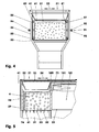
- FIGS. 4 and 5 show the charging chute system (20) after loading a scrap basket volume. This shows the FIG. 4 a cross section and the FIG. 5 a longitudinal section in the region of the Vorchargierfachs (31).
- the push basket (81) has taken up the entire volume of scrap containers.
- the shutter slide (52) is closed.
- the partition (71) is centered on the shaft and seals the shaft-shaped container (101) against the Vorchargierfach (31).
- the on the thrust plate (61) arranged sealing wall (76) has no function in this initial position (64).
- the scrap (4) from the Vorchargierfach (31) in the shaft-shaped container (101) can be promoted.
- the level can be determined, for example, by means of load cells (162).
- the thrust basket (81) by means of the drive unit (91) in the in the FIG. 6 shown front end position (65) promoted.
- the partition (71) is opened.
- the thrust shield (61) pushes the scrap (4) along the bottom (32) until the scrap (4) falls into the shaft-shaped container (101).
- the opening (107) between the Precharging compartment (31) and the shaft-shaped container (101) through the sealing wall (76) closed.
- the push basket (81) can be conveyed back to the starting position (64).
- the scrap (4) is now in the shaft-shaped container (101), as in the FIG. 6 shown. Scrap pieces that may have remained on the floor (32) may be disposed of through the discharge opening (29).
- scrap (4) can be conveyed into the furnace vessel (10). With the ignition of the electrodes (12) in the scrap (4), the melting process begins.
- the exhaust system sucks the exhaust gases generated during the melting through the shaft-shaped container (101) into the suction opening (131).
- a portion of the exhaust gases - depending on the position of the flap (143) - are sucked through the exhaust pipe (141).
- the exhaust gases heated by the melting process release part of their energy to the scrap (4) stored there as they pass through the shaft-shaped container (101).
- the scrap (4) is preheated while cooling the exhaust gases.
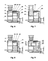
- the push cage (81) can be reloaded as described above. This is in the FIG. 7 shown.
- the partition (71) is closed again.
- the Chargierschacht system (20) thus no exhaust gases from the furnace vessel (10) in the environment (1) reach.
- the electric arc furnace (5) during the loading of the Vorchargierfachs (31) without interruption further scrap (4) melt.
- scrap (4) By means of the pusher device (151), scrap (4), for example, continues to be introduced into the furnace vessel at regular time intervals, for example (10) and the smelting process continues. As soon as the level of scrap (4) in the shaft-shaped container (101) is below the stated limit value, the next contents can be conveyed out of the push basket (81) into the shaft-shaped container (101) without interrupting the furnace melting process. This is done as described above. After conveying the second basket volume of the scrap (4) is for example as in the FIGS. 8 and 10 shown. He has partially slipped out of the thrust basket (81) in the shaft-shaped container (101). The push basket (81) is initially blocked in this position. The sealing wall (76) closes the shaft-shaped container (101) with respect to the precharging compartment (31).
- the FIG. 11 shows a thrust basket (81), the drive unit (91) comprises a motor (95), for example a hydraulic motor.
- the guide system (22, 85) is constructed as in the first embodiment. Parallel to the stroke of the drawer (81) eg in the form of a threaded spindle (86) twisted square steel is arranged. He is for example on the outside (36) of the Chargierschacht system (20) in the longitudinal direction on both end walls (28, 108) of the Chargierschacht system (20) rotatably mounted.
- the thrust basket (81) has a spindle nut (87) which engages around the threaded spindle (86).
- the partition (71) has in the region of the threaded spindle (86) a e.g. A breakthrough (74) sealed by a movable disk and a labyrinth seal.
- the threaded spindle (86) is driven by means of the hydraulic motor (95), which may comprise a reduction gear.
- the hydraulic motor (95) may comprise a reduction gear.
- a threaded spindle (86) with a spindle nut (87) can be arranged on both sides of the thrust basket (81).
- the drive takes place by means of one or two hydraulic motors.
- electric motors can be used.
- the thrust shield (61) is here by means of two cables (96, 97) movable.
- the ropes (96, 97) penetrate longitudinal walls of the Chargierschacht system (20) and are guided on the outer wall of the Chargierschacht system (20) via pulleys and possibly a pulley and / or cable drums.
- the latter are driven for example by means of an electric or hydraulic motor.
- the cable (96) arranged at the push side (62) is hinged at the bottom and the cable (97) at the rear (66) of the push plate (61) at the top.
- a laterally arranged guide roller (88) runs on a guide track (22) arranged, for example, at an angle of 45 degrees to a horizontal plane.
- the guide rollers (88) have, for example, a roller body (89) slidably mounted on an axle.
- the turned plain bearing bushes used in the exemplary embodiment are made of Copper-tin-bronze manufactured with a lead content of eg 7%. Instead of the guide rollers also sliding plates (85) can be used here.
- the cable can e.g. be guided obliquely downwards or upwards.
- a thrust basket (81) in the tensioned rope (96, 97) can be arranged hanging. A centering takes place in each case by the guide plate (68) and when reaching the Hubendlagen (64, 65) through the partition wall (71) and the Abdichtwand (76).
- the FIG. 14 shows a push plate (61) with a guide rod (67). This protrudes, for example, in the direction of the rear wall (28). At her example, four lateral guide rollers (37) are arranged, whose distance from each other is greater than twice the width of the guide rod (67). Further rollers roll on the lower front (38) and rear top (39) on the guide rod (67).
- the drive of the example by means of ribs (63) reinforced thrust shield (61) takes place for example by means of a cylinder-piston unit or by means of a hydraulic motor which drives the guide rod (67) by means of a friction wheel or by means of a toothed pinion. In a pinion drive, a rack is arranged on the guide rod (67), for example.
- the partition wall (71), cf. FIG. 15 is executed in this embodiment separately from the thrust plate (61). For example, it is pivotally mounted about a horizontal axis (75) in the intermediate wall (109) between the Vorchargierfach (31) and the shaft-shaped container (101).
- the partition wall (71) folds under the influence of gravity back into its e.g. vertical starting position. After that, it again seals the precharging compartment (31) and the shaft-shaped container (101) against each other.
- the partition (71) can also be moved separately or be pivotable by means of a drive.
- the pusher blade (61) and the sealing wall (76) are spaced 1.5 meters apart.
- the thrust shield (61) can now be moved further in the direction of the center of the shaft-shaped container (101). For example, so the scrap (4) in the shaft-shaped container (101) can be leveled.
- a pusher (77) is arranged in the push plate (61) also a pusher (77) is arranged.
- This is, for example, constructed as the impact device (151) of the Chargierschacht system (20).
- the thrust shield (78) of this impact device (77) can move relative to the thrust shield (61).
- the shock shield (78) in the illustrated basic position is flush with the thrust side (62) of the thrust shield (61). From this position it can be e.g. by one meter in the direction of the center of the shaft-shaped container (101).
- the width of the thrust shield (78) may correspond to the width of the thrust shield (61) or be formed narrower than this.
- the shock shield (78) may comprise individual segments.
Landscapes
- Engineering & Computer Science (AREA)
- Mechanical Engineering (AREA)
- General Engineering & Computer Science (AREA)
- Chemical & Material Sciences (AREA)
- Manufacturing & Machinery (AREA)
- Materials Engineering (AREA)
- Metallurgy (AREA)
- Organic Chemistry (AREA)
- Vertical, Hearth, Or Arc Furnaces (AREA)
- Manufacture And Refinement Of Metals (AREA)
- Refinement Of Pig-Iron, Manufacture Of Cast Iron, And Steel Manufacture Other Than In Revolving Furnaces (AREA)
Description
- Die Erfindung betrifft ein Chargierschacht-System eines Elektrolichtbogenofens mit einem öffenbaren Verschluss und mit einem eine Ausgabeöffnung und mindestens eine Absaugöffnung umfassenden schachtförmigen Behälter, wobei der Verschluss ein Vorchargierfach verschließt sowie ein Verfahren zum Befüllen.
- Aus der
DE 103 55 549 A1 ist ein derartiges System bekannt. Beim Entladen eines Schrottkorbs in den Schacht können Abgase aus dem Elektrolichtbogenofen unkontrolliert in die Umgebung austreten. - Aus der
DE 31 20 717 A1 ist eine Schrottvorwärmvorrichtung bekannt. Schrott wird in einen vom Abgas durchströmbaren Speicherraum vorgewärmt und mittels eines Stößels in Richtung eines horizontal angeordneten Bodenverschlussschiebers gefördert. Da Schrott beim Vorwärmen verbackt, kann der Bodenverschlussschieber verklemmen. Außerdem besteht beim Öffnen des oberen horizontalen Verschlussschiebers die Gefahr des Ausqualmens der gesundheitsschädlichen Abgase in die Ofenhalle. - Die
EP 0646 758 A1 zeigt eine kaskadenartig aufgebaute Schrottvorwärmvorrichtung mit einer darüber angeordneten Ladezone. Da die warmen Abgase aufsteigen, besteht auch hier die Gefahr des Ausqualmens durch die Klappen hindurch. Außerdem blockieren die geöffneten Klappen das Absaugen während des Beladens. Eine derartige Schrottvorwärmvorrichtung erfordert eine hohe Kranbahnhöhe sowie eine entsprechend hohe Ofenhalle. - Der vorliegenden Erfindung liegt die Problemstellung zugrunde, die Gefahr einer Umweltverschmutzung wesentlich zu verringern.
- Diese Problemstellung wird mit den Merkmalen des Hauptanspruches gelöst. Das Vorchargierfach ist mittels einer öffenbaren Trennwand vom schachtförmigen Behälter getrennt. Im Vorchargierfach ist ein verfahrbares Schubschild angeordnet. Außerdem hat das Schubschild eine der Trennwand zugewandte Schubseite.
- Um den schachtförmigen Behälter zu befüllen, wird bei Lage des Schubschilds in einer Ausgangsposition und bei geschlossener Trennwand der Verschluss geöffnet. Nach dem Laden des Einsatzmaterials in das Vorcharchierfach wird - bei weiterhin geschlossener Trennwand - der Verschluss verschlossen. Die Trennwand wird geöffnet und das Schubschild fördert mit seiner der Trennwand zugewandten Schubseite das Einsatzmaterial in den schachtförmigen Behälter.
- Weitere Einzelheiten der Erfindung ergeben sich aus den Unteransprüchen und der nachfolgenden Beschreibung schematisch dargestellter Ausführungsformen.
- Figur 1:
- Längsschnitt eines Elektrolichtbogenofens mit einem Chargierschacht-Systems;
- Figur 2:
- Detail der Schubkorbführung;
- Figur 3:
- Detail der Abdichtung;
- Figur 4:
- Querschnitt des Vorchargierfachs;
- Figur 5:
- Längsschnitt des beladenen Vorchargierfachs;
- Figur 6:
- Chargierschacht-System mit teilbefülltem schachtförmigem Behälter;
- Figur 7:
- Chargierschacht-System beim Laden des zweiten Schrottkorbvolumens;
- Figur 8:
- Chargierschacht-System nach Befüllen des schachtförmigen Behälters mit dem zweiten Schrottkorbvolumen;
- Figur 9:
- Zurückfahren des Schubkorbs;
- Figur 10:
- Querschnitt durch
Figur 8 ; - Figur 11:
- Schubkorb mit Hydromotorantrieb;
- Figur 12:
- Gebogenes Schubschild;
- Figur 13:
- Schubschild mit Seilzügen;
- Figur 14:
- Schubschild mit Stangenführung;
- Figur 15:
- Schwenkbare Trennwand;
- Figur 16:
- Schubschild mit großem Hub.
- Die
Figur 1 zeigt einen Elektrolichtbogenofen (5) mit einem Ofengefäß (10) und mit einem Chargierschacht-System (20). Mittels eines Elektrolichtbogenofens (5) wird Einsatzmaterial (4), z.B. Stahlschrott mit Hilfe elektrischer und/oder fossiler Energie geschmolzen. Nach dem Schmelzen und Feinen bzw. Homogenisieren wird aus dem Ofengefäß (10) Flüssigstahl mit einer Temperatur von z.B. 1620 Grad Celsius abgestochen. Mit einer derartigen Anlage können pro Stunde mehr als 100 Tonnen Flüssigstahl aus Stahlschrott erzeugt werden. - Da die Dichte des Einsatzmaterials (4) weniger als ein Zehntel der Dichte des Flüssigstahls, z.B. 7850 Kilogramm pro Kubikmeter, beträgt, kann das gesamte, für eine Schmelze erforderliche Einsatzmaterial nur portionsweise in das Ofengefäß (10) gefördert werden. Beispielsweise ist für eine Abstichmasse von 100 Tonnen Flüssigstahl der Einsatz von mehr als 200 Kubikmeter Schrott erforderlich.
- Im Stahlwerk wird der Schrott zunächst auf einem Schrottplatz beispielsweise getrennt nach verschiedenen Schrottqualitäten, z.B. Leichtschrott, Automolbilschrott, Buntmetallschrott, Schrott mit Kunststoff, etc. gelagert. Jeweils ein Schrottkorb (3) wird beispielsweise nach einer vorgeschriebenen Beladefolge beladen. Das Beladevolumen des Schrottkorbs (3) beträgt im Ausführungsbeispiel z.B. 75 Kubikmeter.
- Der so beladene Schrottkorb (3) wird mittels einer Fördervorrichtung (2), z.B. einem Hallenkran (2), an das Chargierschacht-System (20) gefördert.
- Das Fördern des Schrotts (4) vom Schrottplatz zum Chargierschacht-System (20) kann auch mittels anderer diskontinuierlicher oder kontinuierlicher Fördermittel erfolgen.
- Das Chargierschacht-System (20) umfasst ein Vorchargierfach (31) mit einem Verschluss (51) und einen schachtförmigen Behälter (101). Das Vorchargierfach (31) und der schachtförmige Behälter (101) sind mittels einer öffenbaren Trennwand (71) voneinander abgegrenzt.
- Das Vorchargierfach (31) ist im Ausführungsbeispiel ein quaderförmiger Raum mit einem Volumen von z.B. 130 Kubikmetern und mit einem zumindest annähernd ebenen Boden (32). Der Boden (32) kann auch in Richtung der Trennwand (71) schräg abfallend, z.B. mit einem Schrägungswinkel von bis zu 15 Grad, ausgebildet sein. Der Boden (32) ist beispielsweise durch Bleche oder Knüppel einer Dicke von z.B. 100 Millimetern gebildet, die auf in Querrichtung (25) angeordneten Trägern (33), z.B. I-Trägern, Hohlprofilträgern mit quadratischem oder rechteckigem Querschnitt, etc. aufliegen. Diese Träger (33) sind mit einem wassergekühlten Traggerüst (21) des Chargierschacht-Systems (20) verbunden. Dieses Traggerüst (21) dient gleichzeitig als Wasserverteiler.
- Die in Längsrichtung (24) des Chargierschacht-Systems (20) orientierten Seitenwände (26, 27) und die rückseitige Stirnwand (28) sind in das Traggerüst (21) eingebaut. Sie können für Wartungszwecke demontierbar ausgebildet sein. Die Rückwand (28) hat im Ausführungsbeispiel eine Entleerungsöffnung (29). Auch der Boden (32) kann eine Entleerungsöffnung aufweisen. Beispielsweise in Verlängerung des Bodens (32) sind in den Seitenwänden (26, 27) in Längsrichtung (24) orientierte Führungsschienen (22) angeordnet, vgl.
Figur 2 . Die Führungsflächen (23) dieser Führungsschienen (22) schließen mit einer horizontalen Ebene beispielsweise einen Winkel von 45 - 60 Grad ein. Gegebenenfalls kann auch ein Untergriff vorgesehen sein, z.B. als Abhebesicherung. - Die vorderseitige Stirnwand des Vorchargierfachs (31) wird in der Darstellung der
Figur 1 durch die Trennwand (71) gebildet. Diese Trennwand (71), vgl.Figur 3 , ist beispielsweise plattenförmig aus Stahlblech aufgebaut und hat z.B. an ihrer Oberseite (72) und an den Seitenflächen Zentrierschrägen (73) zum Abdichten des schachtförmigen Behälters (101) gegenüber dem Vorchargierfach (31). Die Trennwand (71) kann Versteifungsrippen aufweisen. Die Projektionsfläche der Trennwand (71) in die Ebene der Trennfläche ist größer als die in dieselbe Ebene projizierte Fläche des Schubschilds (61). - Die Oberseite (34) des Vorchargierfachs (31) hat eine z.B. rechteckige Öffnung (35). Die Fläche der Öffnung (35) kann der Fläche des Bodens (32) entsprechen oder kleiner sein als diese.
- In der in der
Figur 1 dargestellten Ausführungsform ist die Oberseite (34) des Vorchargierfachs (31) an einen Trichter (41) angedichtet. Dieser ragt in das Vorchargierfach (31), so dass zumindest die Prismenleisten (22) im Schatten des Trichters (41) liegen. Senkrecht herabfallendes Einsatzmaterial (4) kann damit die Führungsschienen (22) nicht beschädigen. - Der Trichter (41) hat im Ausführungsbeispiel ungekühlte Wandflächen. Der Winkel, den die Trichterflanken (42) mit der Fläche der Öffnung (35) einschließen, beträgt beispielsweise 60 Grad.
- In der Darstellung der
Figur 1 ist oberhalb des Trichters (41) der Verschluss (51) angeordnet. Der Verschluss (51) umfasst einen z.B. hydraulisch angetriebenen Verschlussschieber (52), der zwischen einer geöffneten und einer geschlossenen Endlage hin- und herbewegbar ist. - In der geschlossenen Endlage des Verschlussschiebers (52) ist die Öffnung (35) quasi hermetisch verschlossen. In der geöffneten Endlage des Verschlussschiebers (52), vgl.
Figur 6 , liegt die Oberseite des Trichters (41) vollständig frei. Der Antrieb des Verschlusschiebers (52), z.B. zwei parallel zueinander angeordnete Hydraulikzylinder (53), sind im Ausführungsbeispiel auf dem schachtförmigen Behälter (101) angeordnet. - Es ist auch denkbar, den Verschluss (51) zwischen der Öffnung (35) und dem Trichter (41) anzuordnen. Der Verschlussschieber (52) kann dann entsprechend kleiner gestaltet sein.
- Im Vorchargierfach (31) ist weiterhin ein Schubschild (61) angeordnet. Dies ist eine in Querrichtung (24) des Chargierschacht-Systems (20) orientierte, z.B. verstärkte Platte mit einer Dicke von z.B. 100 Millimetern. In der Darstellung der
Figur 1 ist das Schubschild (61) vertikal angeordnet. Es kann vertikale und/oder horizontale Verstärkungsrippen aufweisen. - Das Schubschild (61) kann auch entlang einer horizontalen und/oder vertikalen Biegelinie gebogen sein. Die Biegelinie liegt in beiden Fällen auf der der Trennwand (71) zugewandten Schubseite (62) des Schubschilds (61).
- Die
Figur 12 zeigt ein schaufelförmig ausgebildetes Schubschild (61). Es hat einen konstanten Krümmungsradius mit vertikaler Biegelinie, der der doppelten Breite des Schubschilds (61) entspricht. Weiterhin ist das Schubschild (61) um eine horizontale Achse gebogen. Auf der Rückseite (66) sind z.B. fünf vertikal orientierte Verstärkungsrippen (63) angeordnet. Gegebenenfalls können auf der Schubseite (62) zusätzliche vertikal orientierte Bleche angeordnet sein, z.B. an den äußeren Rändern des Schubschilds (61). Es ist auch denkbar, das Schubschild (61) im unteren Bereich trapezförmig, V-förmig, halbrund, etc. auszubilden. - In der in der
Figur 1 dargestellten Ausgangslage (64) ist das Schubschild (61) außerhalb des vertikal projizierten Öffnungsquerschnitts, also im Schatten des Trichters (41) angeordnet. - Das Schubschild (61) und die Trennwand (71) bilden im Ausführungsbeispiel Stirnwände (61, 71) eines Schubkorbs (81). Die z.B. sechs Längsträger (82), die die Trennwand (71) und das Schubschild (61) verbinden, haben zusammen beispielsweise eine Zug-Querschnittsfläche von mindestens 1000 guadratmillimeter. Die einzelnen Längsträger (82) können als Voll- oder als Hohlprofile ausgebildet sein. Die Seitenflächen (83) des oben und unten offenen Schubkorbes (81) sind im Ausführungsbeispiel mit Blechen der Dicke 30 Millimeter beplankt. Das maximale Aufnahmevolumen des Schubkorbs (81) ist im Ausführungsbeispiel um 10 % größer als das Volumen des Schrottkorbs (3). Die oberen Längsträger (82) können als Anschlagleisten ausgebildet sein, die den Schubkorb (81) in seiner Bahn halten.
- Das Schubschild (61) und die Trennwand (71) sind in Querrichtung (25) im unteren Bereich angeschrägt, vgl.
Figur 2 . In diesen Schrägen sind z.B. an einer Stützhalterung (84) Gleitplatten (85) angeordnet. Mittels der Gleitplatten (85) ist im Ausführungsbeispiel der Schubkorb (81) in Schwerkraftrichtung und in der Querrichtung (25) abgestützt. - Am Schubschild (61) ist eine Antriebseinheit (91) angeordnet, die sich am Vorchargierfach (31) oder am schachtförmigen Behälter (101) abstützt, vgl.
Figur 4 . Diese Antriebseinheit (91) umfasst im Ausführungsbeispiel zwei Zylinder-Kolben-Einheiten (92), die an der Außenseite (36) des Vorchargierfachs (31) auf beiden Seiten des Schubschilds (61) angeordnet sind. Die einzelne Zylinder-Kolben-Einheit (92) hat beispielsweise einen wassergekühlten Zylindermantel (93) und einen in diesem geführten Kolben mit einer Kolbenstange (94). Der Kolbendurchmesser beträgt beispielsweise 300 Millimeter, der Kolbenstangendurchmesser 160 Millimeter. Der Betriebsdruck der Zylinder-Kolben-Einheiten (92) beträgt z.B. 160 x 105 Pascal. Der Hub des Kolbens ist beispielsweise 5,4 Meter. - Der schachtförmige Behälter (101) hat z.B. ein Gesamtvolumen von 200 Kubikmetern und weist in vertikaler Richtung vier Bereiche (111 - 114) auf. In allen Bereichen (111 - 114) hat der schachtförmige Behälter (101) zumindest annähernd einen rechteckigen Querschnitt normal zu einer Vertikalen und glatte Wände (102). Im unteren Bereich kann er leicht konisch verjüngt sein. Der schachtförmige Behälter (101) kann in Längsrichtung (24), vgl.
Figur 1 oder in Querrichtung (25) zum Vorchargierfach (31) angeordnet sein. - Der oberste Bereich (111), seine Höhe beträgt etwa 40 % der Behälterhöhe - hat an mindestens einer in Querrichtung (25) orientierten Stirnwänden eine Absaugöffnung (131) zum Anschluss der Absaugleitung (130), vgl.
Figur 10 . Diese Absaugöffnung (131) hat in der Darstellung derFigur 1 einen zumindest annähernd dreieckförmigen Querschnitt mit einer Querschnittsfläche von beispielsweise 1,4 Quadratmetern. Der Querschnitt kann auch rund, rechteckig, oval, etc. ausgebildet sein. Der schachtförmige Behälter (101) kann auch mehrere Absaugöffnungen (131) aufweisen. Die Unterkante der Absaugöffnung (131) liegt oberhalb der Ebene der Oberkante des Schubschilds (61). - In diesem obersten Bereich (111) führen die Führungsschienen (22) beispielsweise bis zu der den schachtförmigen Behälter in Längsrichtung (24) begrenzenden ungekühlten Wand (103). In Richtung des Vorchargierfaches (31) ist dieser Bereich in der Darstellung der
Figur 1 mittels der Trennwand (71) abgegrenzt. - Im zweiten Bereich (112) ist der Querschnitt des schachtförmigen Behälters (101) an seinen in Querrichtung (25) orientierten Stirnwänden (104) von oben nach unten verjüngt, vgl.
Figur 10 . Der von der Behälterflanke (105) mit einer horizontalen Ebene eingeschlossene Winkel entspricht dem von der Trichterflanke (42) mit dieser Ebene eingeschlossenen Winkel. - Der dritte Bereich (113) hat einen konstanten Querschnitt. Seine Höhe beträgt z.B. 25 % der Höhe des schachtförmigen Behälters (101). Gegebenenfalls kann dieser Bereich (113) entfallen, wenn die Verjüngung des schachtförmigen Behälters (101) des zweiten Bereichs (112) bis in oder an den untersten Bereich (114) geführt ist.
- Der unterste Bereich (114) weist beispielsweise an der Seitenwand (103) eine Ausgabeöffnung (106) auf. Diese Ausgabeöffnung (106) korrespondiert beispielsweise mit einer Öffnung (11) des Gefäßes (10) des Elektrolichbogenofens (5). Durch diese Öffnungen (106, 11) hindurch wird das Einsatzmaterial (4) aus dem schachtförmigen Behälter (101) in das Gefäß (10) des Elektrolichtbogenofens (5) gefördert.
- Zum Fördern des Einsatzmaterials (4) im Bereich des schachtförmigen Behälters (101) verfügt das Chargierschacht-System (20) beispielsweise über eine Stoßvorrichtung (151). Durch Verfahren eines Stößels (152) der Stoßvorrichtung (151) werden einzelne Portionen des Einsatzmaterials (4) in das Gefäß (10) gefördert.
- Das Fördern des Einsatzmaterials (4) aus dem schachtförmigen Behälter in das Gefäß (10) kann auch mittels Schwerkraft, einer Schwenkvorrichtung, einer Rüttelvorrichtung, einem Zugmitteltrieb, etc. erfolgen.
- An der dem Ofengefäß (10) zugewandten Seite des Chargierschacht-Systems (20) ist eine Abgasleitung (141) angeordnet, die am oberen Ende in den schachtförmigen Behälter (101) mündet. Der Leitungsmantel dieser Abgasleitung (141) ist aus wassergekühlten Rohren (142) aufgebaut. In der Abgasleitung (141) ist eine einstellbare Klappe (143) eingebaut. Dies kann, wie dargestellt, eine sogenannte Schmetterlingsklappe oder eine Lamellenklappe sein.
- Im Ausführungsbeispiel ist das gesamte Chargierschacht-System (20) verfahrbar augebildet. Beispielsweise kann das System (20) mittels eines Antriebs und der Rollen (161) um einen Hub von etwa zwei Metern vom Ofengefäß (10) weg verfahren werden. So werden Wartungsarbeiten am Ofengefäß (10) oder ein Herausnehmen des Ofengefäßes (10) nicht behindert.
- Um das Einsatzmaterial (4) zu chargieren, wird zunächst der befüllte Schrottkorb (3) z.B. mittels des Hallenkrans (2) über dem Verschluss (51) positioniert. Das Schubschild (61) ist in der Ausgangsposition (64), die Trennwand (71) ist geschlossen. Nach dem Öffnen des Verschlusses (51) werden die Schrottkorbschalen (6) z.B. hydraulisch geöffnet. Der Schrott (4) fällt in das Vorchargierfach (31) zwischen das Schubschild (61) und die Trennwand (71), im Ausführungsbeispiel also in den Schubkorb (81). Nach dem Entleeren des Schrottkorbs (3) kann dieser sowie der Verschluss (51) geschlossen werden. Das Chargierschacht-System (20) ist nun vollständig geschlossen.
- Die
Figuren 4 und 5 zeigen das Chargierschacht-System (20) nach dem Laden eines Schrottkorbvolumens. Hierbei zeigt dieFigur 4 einen Querschnitt und dieFigur 5 einen Längsschnitt im Bereich des Vorchargierfachs (31). Der Schubkorb (81) hat das gesamte Schrottkorbvolumen aufgenommen. Der Verschlusschieber (52) ist geschlossen. Die Trennwand (71) ist am Schacht zentriert und dichtet den schachtförmigen Behälter (101) gegen das Vorchargierfach (31) ab. Die am Schubschild (61) angeordnete Abdichtwand (76) hat in dieser Ausgangslage (64) keine Funktion. - Sobald das Niveau des Einsatzmaterials (4) im schachtförmigen Behälter (101) unterhalb eines vorgegebenen Grenzwertes liegt, kann der Schrott (4) aus dem Vorchargierfach (31) in den schachtförmigen Behälter (101) gefördert werden. Das Niveau kann beispielsweise mittels Wägezellen (162) ermittelt werden.
- Hierzu wird der Schubkorb (81) mittels der Antriebseinheit (91) in die in der
Figur 6 dargestellte vordere Endlage (65) gefördert. Hierbei wird die Trennwand (71) geöffnet. Das Schubschild (61) schiebt den Schrott (4) entlang des Bodens (32), bis der Schrott (4) in den schachtförmigen Behälter (101) fällt. In der vorderen Endlage (65) ist im Ausführungsbeispiel die Öffnung (107) zwischen dem Vorchargierfach (31) und dem schachtförmigen Behälter (101) durch die Abdichtwand (76) verschlossen. Nach dem Entleeren des Schubkorbs (81) kann der Schubkorb (81) wieder in die Ausgangslage (64) gefördert werden. Der Schrott (4) liegt jetzt im schachtförmigen Behälter (101), wie in derFigur 6 dargestellt. Schrottteile, die gegebenenfalls auf dem Boden (32) liegengeblieben sind, können durch die Entleerungsöffnung (29) hindurch entsorgt werden. - Nun kann mittels der Stoßvorrichtung (151) Schrott (4) in das Ofengefäß (10) gefördert werden. Mit dem Zünden der Elektroden (12) im Schrott (4) beginnt der Schmelzprozess. Die Absauganlage saugt die während des Schmelzens entstehenden Abgase durch den schachtförmigen Behälter (101) in die Absaugöffnung (131). Gegebenenfalls kann ein Teil der Abgase - je nach Stellung der Klappe (143) - durch die Abgasleitung (141) gesaugt werden.
- Die durch den Schmelzprozeß erwärmten Abgase geben beim Durchströmen des schachtförmigen Behälters (101) einen Teil ihrer Energie an den dort gelagerten Schrott (4) ab. Der Schrott (4) wird vorgewärmt bei gleichzeitiger Abkühlung der Abgase.
- In der Ausgangslage (64) kann der Schubkorb (81) wie oben beschrieben neu beladen werden. Dies ist in der
Figur 7 dargestellt. Die Trennwand (71) ist wieder verschlossen. Beim Beladen des Chargierschacht-Systems (20) können somit keine Abgase aus dem Ofengefäß (10) in die Umgebung (1) gelangen. Beispielsweise kann der Elektrolichtbogenofen (5) während des Beladens des Vorchargierfachs (31) ohne Unterbrechung weiter Schrott (4) einschmelzen. - Mittels der Stoßvorrichtung (151) wird nun z.B. in regelmäßigen Zeitintervallen weiter Schrott (4) in das Ofengefäß (10) gefördert und der Schmelzprozess fortgesetzt. Sobald das Niveau des Schrotts (4) im schachtförmigen Behälter (101) unterhalb des genannten Grenzwerts ist, kann - ohne Unterbrechen des Ofenschmelzprozesses - der nächste Inhalt aus dem Schubkorb (81) in den schachtförmigen Behälter (101) gefördert werden. Dies erfolgt wie oben beschrieben. Nach dem Fördern des zweiten Schubkorbvolumens liegt der Schrott (4) beispielsweise wie in den
Figuren 8 und10 dargestellt. Er ist bereichsweise aus dem Schubkorb (81) in den schachtförmigen Behälter (101) gerutscht. Der Schubkorb (81) ist in dieser Stellung zunächst blockiert. Die Abdichtwand (76) verschließt den schachtförmigen Behälter (101) gegenüber dem Vorchargierfach (31). - Beim weiteren Betrieb dringen die Abgase durch die gesamte Schrottsäule, so dass sämtlicher Schrott (4) im schachtförmigen Behälter (101) vorgewärmt wird. Mittels der Stoßvorrichtung (151) wird weiter Schrott (4) in das Ofengefäß (10) gefördert, so dass mit zunehmender Prozeßzeit die Höhe der Schrottsäule sinkt. Sobald der genannte Grenzwert der Niveauhöhe unterschritten wird, verfährt der Schubkorb wieder in die Ausgangslage (64), vgl.
Figur 9 . Die nächste Korbfüllung, z.B. der erste Korb für die nächste Schmelze, kann in das Vorchargierfach (31) geladen werden. Nach erfolgtem Abstich wird der bereits vorgewärmte Schrott (4) für die nächste Schmelze in das Ofengefäß (10) gefördert. - Die
Figur 11 zeigt einen Schubkorb (81), dessen Antriebseinheit (91) einen Motor (95), z.B. einen Hydromotor umfasst. Das Führungssystem (22, 85) ist so aufgebaut wie im ersten Ausführungsbeispiel. Parallel zum Hubweg des Schubkorbes (81) ist z.B. ein in Form einer Gewindespindel (86) tordierter Vierkantstahl angeordnet. Er ist beispielsweise an der Außenseite (36) des Chargierschacht-Systems (20) in Längsrichtung an beiden Stirnwänden (28, 108) des Chargierschacht-Systems (20) drehbar gelagert. - Der Schubkorb (81) hat eine Spindelmutter (87), die die Gewindespindel (86) umgreift. Die Trennwand (71) hat im Bereich der Gewindespindel (86) einen z.B. mittels einer beweglichen Scheibe und einer Labyrinthdichtung abgedichteten Durchbruch (74).
- Zum Verfahren des Schubkorbs (81) wird die Gewindespindel (86) mittels des Hydromotors (95), der ein Untersetzungsgetriebe umfassen kann, angetrieben. Gegebenenfalls kann auf beiden Seiten des Schubkorbs (81) eine Gewindespindel (86) mit einer Spindelmutter (87) angeordnet sein. Der Antrieb erfolgt mittels eines oder zweier Hydromotoren. Gegebenenfalls können auch Elektromotoren eingesetzt werden.
- Eine weitere Antriebsvariante ist in der
Figur 13 dargestellt. Das Schubschild (61) ist hier mittels zweier Seilzüge (96, 97) bewegbar. Die Seile (96, 97) durchdringen längsseitige Wände des Chargierschacht-Systems (20) und sind an der Außenwand des Chargierschacht-Systems (20) über Umlenkrollen und gegebenenfalls über einen Flaschenzug und/oder Seiltrommeln geführt. Letztere werden beispielsweise mittels eines Elektro- oder Hydromotors angetrieben. In dem dargestellten Längsschnitt ist das an der Schubseite (62) angeordnete Seil (96) unten und das Seil (97) an der Rückseite (66) des Schubschilds (61) oben angeschlagen. Auf beiden Seiten läuft eine seitlich angeordnete Führungsrolle (88) auf einer z.B. in einem Winkel von 45 Grad zu einer horizontalen Ebene angeordneten Führungsbahn (22). Die Führungsrollen (88) haben beispielsweise einen auf einer Achse gleitgelagerten Rollenkörper (89). Die im Ausführungsbeispiel eingesetzten gedrehten Gleitlagerbuchsen sind aus Kupfer-Zinn-Bronze mit einem Bleianteil von z.B. 7 % hergestellt. Anstatt der Führungsrollen können hier auch Gleitplatten (85) eingesetzt werden. - Es kann auch ein einziges Seil (96; 97) eingesetzt werden. Je nach Drehrichtung des Motors (95) wird der schubschildseitige oder der trennwandseitige Seilabschnitt (96; 97) gezogen und damit das Schubschild (61) in die Ausgangslage (64) oder in die Endlage (65) gefördert.
- Bei einer derartigen Ausführungsform kann gegebenenfalls auf die Abhebesicherung und/oder die Tragrollen (88) verzichtet werden. Hierfür kann der Seilzug z.B. schräg nach unten oder nach oben geführt werden. Auch kann ein Schubkorb (81) im gespannten Seil (96; 97) hängend angeordnet sein. Eine Zentrierung erfolgt jeweils durch das Führungsblech (68) sowie beim Erreichen der Hubendlagen (64, 65) durch die Trennwand (71) und die Abdichtwand (76).
- Die
Figur 14 zeigt ein Schubschild (61) mit einer Führungsstange (67). Diese ragt beispielsweise in Richtung der Rückwand (28). An ihr sind beispielsweise vier seitliche Führungsrollen (37) angeordnet, deren Abstand voneinander größer ist als die doppelte Breite der Führungsstange (67). Weitere Rollen wälzen vorne unten (38) und hinten oben (39) auf der Führungsstange (67) ab. Der Antrieb des z.B. mittels Rippen (63) verstärkten Schubschilds (61) erfolgt z.B. mittels einer Zylinder-Kolben-Einheit oder mittels eines Hydromotors, der mittels eines Reibrades oder mittels eines verzahnten Ritzels die Führungsstange (67) antreibt. Bei einem Ritzelantrieb ist an der Führungsstange (67) beispielsweise eine Zahnstange angeordnet. - Die Trennwand (71), vgl.
Figur 15 , ist in diesem Ausführungsbeispiel getrennt vom Schubschild (61) ausgeführt. Beispielsweise ist sie um eine horizontale Achse (75) schwenkbar in der Zwischenwand (109) zwischen dem Vorchargierfach (31) und dem schachtförmigen Behälter (101) angeordnet. - Zum Fördern des Schrotts (4) aus dem Vorchargierfach (31) in den schachtförmigen Behälter (101) schiebt das verfahrbare Schubschild (61) den Schrott (4) in Richtung des schachtförmigen Behälters (101). Der Schrott (4) drückt die Trennwand (71) auf, die in der Darstellung der
Figur 15 z.B. gegen den Uhrzeigersinn schwenkt. Sobald das Schubschild (61) die Zwischenwand (109) passiert, legt sich die Trennwand (71) auf dem Schubschild (61) ab. Die mit dem Schubschild (61) mitgeführte Abdichtwand (76) wird gegen die Zwischenwand (109) gedrückt. Auch in diesem Ausführungsbeispiel wird das Entweichen von Abgasen aus dem schachtförmigen Behälter (101) durch das Vorchargierfach (31) hindurch verhindert. - Beim Zurückfahren des Schubschilds (61) klappt die Trennwand (71) unter dem Einfluss der Schwerkraft wieder in ihre z.B. vertikale Ausgangslage. Hiernach dichtet sie wieder das Vorchargierfach (31) und den schachtförmigen Behälter (101) gegeneinander ab.
- Die Trennwand (71) kann auch separat verfahrbar oder mittels eines Antriebs schwenkbar sein.
- In der
Figur 16 sind das Schubschild (61) und die Abdichtwand (76) beispielsweise um 1,5 Meter voneinander beabstandet. Das Schubschild (61) kann nun weiter in Richtung der Mitte des schachtförmigen Behälters (101) verfahren werden. Beispielsweise kann so der Schrott (4) im schachtförmigen Behälter (101) planiert werden. - Im Schubschild (61) ist außerdem eine Stoßvorrichtung (77) angeordnet. Diese ist beispielsweise so aufgebaut wie die Stoßvorrichtung (151) des Chargierschacht-Systems (20). Das Stoßschild (78) dieser Stoßvorrichtung (77) kann relativ zum Schubschild (61) verfahren. Hierbei ist das Stoßschild (78) in der dargestellten Grundposition bündig mit der Schubseite (62) des Schubschilds (61). Aus dieser Position heraus kann es z.B. um einen Meter in Richtung der Mitte des schachtförmigen Behälters (101) verfahren werden. Die Breite des Stoßschilds (78) kann der Breite des Schubschilds (61) entsprechen oder schmäler als dieses ausgebildet sein. Das Stoßschild (78) kann einzelne Segmente umfassen.
- Auch Kombinationen der verschiedenen Ausführungsbeispiele sind denkbar.
-
- 1
- Umgebung
- 2
- Fördervorrichtung, Hallenkran
- 3
- Schrottkorb
- 4
- Einsatzmaterial, Schrott
- 5
- Elektrolichtbogenofen
- 6
- Schrottkorbschalen
- 10
- Ofengefäß
- 11
- Öffnung
- 12
- Elektroden
- 20
- Chargierschacht-System
- 21
- Traggerüst
- 22
- Führungsschiene, Prismenleisten
- 23
- Führungsflächen
- 24
- Längsrichtung
- 25
- Querrichtung
- 26
- Seitenwände
- 27
- Seitenwände
- 28
- Stirnwand, Rückwand
- 29
- Entleerungsöffnung
- 31
- Vorchargierfach
- 32
- Boden
- 33
- Träger
- 34
- Oberseite
- 35
- Öffnung
- 36
- Außenseite
- 37
- Führungsrollen
- 38
- Führungsrolle vorne unten
- 39
- Führungsrolle hinten oben
- 41
- Trichter, Befülltrichter
- 42
- Trichterflanke
- 51
- Verschluss
- 52
- Verschlussschieber
- 53
- Zylinder-Kolben-Einheit, hydraulisch
- 61
- Schubschild, Stirnwand
- 62
- Schubseite
- 63
- Verstärkungsrippen
- 64
- Ausgangslage
- 65
- vordere Endlage
- 66
- Rückseite
- 67
- Führungsstange
- 68
- Führungsblech
- 71
- Trennwand; Stirnwand
- 72
- Oberseite
- 73
- Zentrierschrägen
- 74
- Durchbruch in (71)
- 75
- horizontale Achse
- 76
- Abdichtwand
- 77
- Stoßvorrichtung
- 78
- Stoßschild
- 81
- Schubkorb
- 82
- Längsträger
- 83
- Seitenflächen
- 84
- Stützhalterung
- 85
- Gleitplatten
- 86
- Gewindespindel
- 87
- Spindelmutter
- 88
- Führungsrolle
- 89
- Rollenkörper
- 91
- Antriebseinheit
- 92
- Zylinder-Kolben-Einheit
- 93
- Zylindermantel
- 94
- Kolbenstange
- 95
- Motor, Hydromotor
- 96
- Seilzug
- 97
- Seilzug
- 101
- schachtförmiger Behälter
- 102
- Wände
- 103
- ungekühlte Wand
- 104
- Seitenwände
- 105
- Behälterflanke
- 106
- Ausgabeöffnung
- 107
- Öffnung
- 108
- Stirnwand
- 109
- Zwischenwand
- 111
- oberster Bereich
- 112
- zweiter Bereich
- 113
- dritter Bereich
- 114
- unterster Bereich
- 130
- Absaugleitung
- 131
- Absaugöffnung
- 141
- Abgasleitung
- 142
- wassergekühlte Rohre
- 143
- Klappe
- 151
- Stoßvorrichtung
- 152
- Stößel
- 161
- Rollen
- 162
- Wägezellen
Claims (7)
- Chargierschacht-System (20) eines Elektrolichtbogenofens (5) mit einem öffenbaren Verschluss (51) und mit einem eine Ausgabeöffnung (106) und mindestens eine Absaugöffnung (131) umfassenden schachtförmigen Behälter (101), wobei der Verschluss (51) ein Vorchargierfach (31) verschließt, dadurch gekennzeichnet- dass das Vorchargierfach (31) mittels einer öffenbaren Trennwand (71) vom schachtförmigen Behälter (101) getrennt ist,- dass im Vorchargierfach (31) ein verfahrbares Schubschild (61) angeordnet ist und- dass das Schubschild (61) eine der Trennwand (71) zugewandte Schubseite (62) hat.
- Chargierschacht-System (20) nach Anspruch 1, dadurch gekennzeichnet, dass das Schubschild (61) schaufelförmig ausgebildet ist.
- Chargierschacht-System (20) nach Anspruch 1, dadurch gekennzeichnet, dass das Vorchargierfach (31) einen Befülltrichter (41) trägt.
- Chargierschacht-System (20) nach Anspruch 1, dadurch gekennzeichnet, dass die Projektionsfläche der Trennwand (71) in die Ebene der Trennfläche größer ist als die in dieselbe Ebene projizierte Fläche des Schubschilds (61).
- Chargierschacht-System (20) nach Anspruch 1, dadurch gekennzeichnet, dass das Schubschild (61) und die Trennwand (71) Stirnwände eines Schubkorbes (81) bilden.
- Chargierschacht-System (20) nach Anspruch 5, dadurch gekennzeichnet, dass der Schubkorb (81) bodenlos ist,
- Verfahren zum Befüllen eines eine Ausgabeöffnung (106) und mindestens eine Absaugöffnung (131) umfassenden schachtförmigen Behälters (101) eines Chargierschacht-Systems (20) nach Anspruch 1,- wobei bei Lage des Schubschilds (61) in einer Ausgangsposition (64) und bei geschlossener Trennwand (71) der Verschluss (51) geöffnet wird,- wobei nach dem Laden des Einsatzmaterials (4) in das Vorchargierfach (31) - bei weiterhin geschlossener Trennwand (71) - der Verschluss (51) verschlossen wird und- wobei die Trennwand (71) geöffnet wird und das Schubschild (61) mit seiner der Trennwand (71) zugewandten Schubseite (62) das Einsatzmaterial (4) in den schachtförmigen Behälter (101) fördert.
Applications Claiming Priority (2)
| Application Number | Priority Date | Filing Date | Title |
|---|---|---|---|
| DE201010045825 DE102010045825A1 (de) | 2010-09-20 | 2010-09-20 | Chargierschacht-System und Verfahren zum Befüllen |
| PCT/DE2011/001741 WO2012062254A1 (de) | 2010-09-20 | 2011-09-20 | Chargierschacht-system und verfahren zum befüllen |
Publications (2)
| Publication Number | Publication Date |
|---|---|
| EP2619336A1 EP2619336A1 (de) | 2013-07-31 |
| EP2619336B1 true EP2619336B1 (de) | 2014-11-19 |
Family
ID=45606892
Family Applications (1)
| Application Number | Title | Priority Date | Filing Date |
|---|---|---|---|
| EP20110817511 Active EP2619336B1 (de) | 2010-09-20 | 2011-09-20 | Chargierschacht-system und verfahren zum befüllen |
Country Status (8)
| Country | Link |
|---|---|
| US (1) | US20140126604A1 (de) |
| EP (1) | EP2619336B1 (de) |
| JP (1) | JP2013543098A (de) |
| KR (1) | KR20140024831A (de) |
| CN (1) | CN103180466B (de) |
| DE (1) | DE102010045825A1 (de) |
| RU (1) | RU2013118327A (de) |
| WO (1) | WO2012062254A1 (de) |
Families Citing this family (14)
| Publication number | Priority date | Publication date | Assignee | Title |
|---|---|---|---|---|
| EP2682700A1 (de) * | 2012-07-03 | 2014-01-08 | Steb S.r.l. | Stahlherstellungsanlage |
| CN102721274B (zh) * | 2012-07-04 | 2014-01-08 | 中冶赛迪工程技术股份有限公司 | 一种电弧炉的密封加料装置和密封方法 |
| DE102012014142B3 (de) * | 2012-07-18 | 2013-12-12 | Inteco Special Melting Technologies Gmbh | Schrottvorwärm- und Zuführsystem |
| CN104266490A (zh) * | 2014-10-22 | 2015-01-07 | 常州泉汇机械制造有限公司 | 一种炉辊 |
| DE102014115671A1 (de) | 2014-10-28 | 2016-05-12 | Gerhard Fuchs | Schmelzvorrichtung und schmelzverfahren |
| DE102014018050B4 (de) * | 2014-12-05 | 2016-09-08 | Kr Tec Gmbh | Vorwärmvorrichtung mit Lastaufnahmemittel |
| EP3467418B1 (de) * | 2016-05-30 | 2025-11-12 | CISDI Engineering Co., Ltd | Zuführvorrichtung für einen elektrischen lichtbogenofen sowie rauchgas und temperaturregelverfahren |
| DE102017107128B4 (de) | 2017-04-03 | 2026-02-26 | Gerhard Fuchs | Beschickungsvorrichtung für ein Ofengefäß |
| DK180737B1 (en) * | 2020-07-06 | 2022-02-10 | Marel Iceland Ehf | A system and a method for automatically placing ice into boxes having two or more different widths |
| CN113021489A (zh) * | 2021-03-16 | 2021-06-25 | 长虹美菱股份有限公司 | 冰箱吸塑内衬冲孔设备可移动工作台的废料收集装置 |
| CN112960153B (zh) * | 2021-04-06 | 2023-06-02 | 甘肃润康药业有限公司 | 一种消毒剂罐装设备 |
| CN113335570B (zh) * | 2021-06-04 | 2023-04-28 | 临沂丰晨粮油食品有限公司 | 一种用于变性淀粉食品加工装盒机器 |
| ES3013299B2 (es) * | 2023-10-11 | 2025-12-18 | Ind Furnaces Insertec S L | Sistema de fusion lateral |
| DE102024001628A1 (de) * | 2024-05-21 | 2025-11-27 | KR-Tec AG | Chargierschacht-System mit erhöhter Zuverlässigkeit |
Family Cites Families (11)
| Publication number | Priority date | Publication date | Assignee | Title |
|---|---|---|---|---|
| US2661327A (en) * | 1950-12-04 | 1953-12-01 | Dalin David | Apparatus for the destructive distillation of oil shale |
| DE3120717C2 (de) * | 1981-05-25 | 1983-06-30 | Schweizerische Aluminium AG, 3965 Chippis | Vorrichtung zur Wärmebehandlung von Schrott |
| JPH07190629A (ja) * | 1993-04-15 | 1995-07-28 | Ishikawajima Harima Heavy Ind Co Ltd | スクラップ原料予熱装入装置 |
| DE4407861C1 (de) * | 1994-03-04 | 1995-06-14 | Mannesmann Ag | Beschickungsvorrichtung für Lichtbogenofen |
| DE19807616A1 (de) * | 1998-02-13 | 1999-08-26 | Mannesmann Ag | Beschickungseinrichtung für Niederschachtöfen |
| DE19902438A1 (de) * | 1999-01-22 | 2000-07-27 | Sms Demag Ag | Vorrichtung zum Vorwärmen von Schrott |
| DE19926059A1 (de) * | 1999-06-08 | 2000-12-14 | Sms Demag Ag | Vorwärmeinrichtung |
| DE19945489A1 (de) * | 1999-09-22 | 2001-04-05 | Sms Demag Ag | Verfahren und Einrichtung zum Einbringen von Schüttgut in ein metallurgisches Gefäss |
| DE10014711A1 (de) * | 2000-03-24 | 2001-09-27 | Hertwich Engineering Ges M B H | Zweikammerofen zum Tauchschmelzen von kontaminiertem Aluminiumschrott |
| DE10333764B3 (de) * | 2003-07-23 | 2004-12-30 | Outokumpu Oy | Verfahren zum Chargieren von feinkörnigen Metallen in einen Elektrolichtbogenofen |
| DE10355549A1 (de) | 2003-11-27 | 2005-06-23 | Intracon Gmbh | Chargiergutvorwärmer |
-
2010
- 2010-09-20 DE DE201010045825 patent/DE102010045825A1/de not_active Withdrawn
-
2011
- 2011-09-20 KR KR20137009711A patent/KR20140024831A/ko not_active Withdrawn
- 2011-09-20 RU RU2013118327/02A patent/RU2013118327A/ru not_active Application Discontinuation
- 2011-09-20 CN CN201180051977.0A patent/CN103180466B/zh not_active Expired - Fee Related
- 2011-09-20 WO PCT/DE2011/001741 patent/WO2012062254A1/de not_active Ceased
- 2011-09-20 EP EP20110817511 patent/EP2619336B1/de active Active
- 2011-09-20 JP JP2013529547A patent/JP2013543098A/ja not_active Withdrawn
-
2013
- 2013-03-20 US US13/847,512 patent/US20140126604A1/en not_active Abandoned
Also Published As
| Publication number | Publication date |
|---|---|
| KR20140024831A (ko) | 2014-03-03 |
| US20140126604A1 (en) | 2014-05-08 |
| WO2012062254A1 (de) | 2012-05-18 |
| JP2013543098A (ja) | 2013-11-28 |
| CN103180466A (zh) | 2013-06-26 |
| EP2619336A1 (de) | 2013-07-31 |
| CN103180466B (zh) | 2015-02-18 |
| DE102010045825A1 (de) | 2012-03-22 |
| RU2013118327A (ru) | 2014-10-27 |
Similar Documents
| Publication | Publication Date | Title |
|---|---|---|
| EP2619336A1 (de) | Chargierschacht-system und verfahren zum befüllen | |
| EP2633253B1 (de) | Schrott-schubvorrichtung | |
| EP3099437A1 (de) | GIEß-WALZ -VERBUNDANLAGE MIT SCHWENKBAREM ROLLGANGSABSCHNITT | |
| AT412539B (de) | Zweiwalzengiesseinrichtung | |
| WO2014012655A2 (de) | Schrottvorwärm- und zuführsystem | |
| EP2275764B1 (de) | Vorrichtung zur Positionierung eines Materialkorbs | |
| DE202010018098U1 (de) | Chargierschacht-System | |
| DE19807616A1 (de) | Beschickungseinrichtung für Niederschachtöfen | |
| WO1980001277A1 (fr) | Procede pour le remplissage de soutes et dispositif pour sa mise en oeuvre | |
| WO2016066163A1 (de) | Schmelzvorrichtung und schmelzverfahren | |
| DE202022104180U1 (de) | Schlackentrichter zur Schlackenabgabe ohne Maschinenstillstand | |
| DE1102194B (de) | Verfahren und Vorrichtung zum Schnellchargieren von Stahlwerksoefen | |
| DE102009054430B4 (de) | Vorrichtung und Verfahren zum Entleeren eines gelöschten oder ungelöschten Kokses aus einem Kokslöschwagen in eine Aufnahmevorrichtung | |
| DE102017107128B4 (de) | Beschickungsvorrichtung für ein Ofengefäß | |
| DE102024001628A1 (de) | Chargierschacht-System mit erhöhter Zuverlässigkeit | |
| EP2603616B1 (de) | Schmelzmetallurgische anlage mit beschickungselement | |
| DE102018126161A1 (de) | Anlage zum Einschmelzen von Schrott und Verfahren zum Betreiben der Anlage | |
| DE2143459C3 (de) | Planiereinrichtung für horizontale Verkokungsöfen | |
| DE2831460C2 (de) | Planiereinrichtung für Horizontalkammeröfen | |
| DE500432C (de) | Vorrichtung zum Destillieren von Kohle oder aehnlichen kohlehaltigen Stoffen | |
| DE102014018050A1 (de) | Vorwärmvorrichtung mit Lastaufnahmemittel | |
| DE3327365A1 (de) | Vorrichtung zum fuellen von containern | |
| DE2655983B2 (de) | Vorrichtung zur Beschickung eines Schachtofens, insbesondere eines Hochofens | |
| DE2145516A1 (de) | Vorrichtung zum auffuellen von gefuellten horizontalen verkokungsoefen mit kohle | |
| DE202010002422U1 (de) | System zum Lagern und Zuführen von Festbrennstoff zu einer Festbrennstoff-Heizanlage |
Legal Events
| Date | Code | Title | Description |
|---|---|---|---|
| PUAI | Public reference made under article 153(3) epc to a published international application that has entered the european phase |
Free format text: ORIGINAL CODE: 0009012 |
|
| 17P | Request for examination filed |
Effective date: 20130418 |
|
| AK | Designated contracting states |
Kind code of ref document: A1 Designated state(s): AL AT BE BG CH CY CZ DE DK EE ES FI FR GB GR HR HU IE IS IT LI LT LU LV MC MK MT NL NO PL PT RO RS SE SI SK SM TR |
|
| DAX | Request for extension of the european patent (deleted) | ||
| GRAP | Despatch of communication of intention to grant a patent |
Free format text: ORIGINAL CODE: EPIDOSNIGR1 |
|
| INTG | Intention to grant announced |
Effective date: 20140606 |
|
| GRAS | Grant fee paid |
Free format text: ORIGINAL CODE: EPIDOSNIGR3 |
|
| GRAA | (expected) grant |
Free format text: ORIGINAL CODE: 0009210 |
|
| AK | Designated contracting states |
Kind code of ref document: B1 Designated state(s): AL AT BE BG CH CY CZ DE DK EE ES FI FR GB GR HR HU IE IS IT LI LT LU LV MC MK MT NL NO PL PT RO RS SE SI SK SM TR |
|
| REG | Reference to a national code |
Ref country code: GB Ref legal event code: FG4D Free format text: NOT ENGLISH |
|
| REG | Reference to a national code |
Ref country code: CH Ref legal event code: EP |
|
| REG | Reference to a national code |
Ref country code: AT Ref legal event code: REF Ref document number: 697099 Country of ref document: AT Kind code of ref document: T Effective date: 20141215 |
|
| REG | Reference to a national code |
Ref country code: IE Ref legal event code: FG4D Free format text: LANGUAGE OF EP DOCUMENT: GERMAN |
|
| REG | Reference to a national code |
Ref country code: DE Ref legal event code: R096 Ref document number: 502011005060 Country of ref document: DE Effective date: 20141231 |
|
| REG | Reference to a national code |
Ref country code: NL Ref legal event code: VDEP Effective date: 20141119 |
|
| REG | Reference to a national code |
Ref country code: LT Ref legal event code: MG4D |
|
| PG25 | Lapsed in a contracting state [announced via postgrant information from national office to epo] |
Ref country code: ES Free format text: LAPSE BECAUSE OF FAILURE TO SUBMIT A TRANSLATION OF THE DESCRIPTION OR TO PAY THE FEE WITHIN THE PRESCRIBED TIME-LIMIT Effective date: 20141119 Ref country code: LT Free format text: LAPSE BECAUSE OF FAILURE TO SUBMIT A TRANSLATION OF THE DESCRIPTION OR TO PAY THE FEE WITHIN THE PRESCRIBED TIME-LIMIT Effective date: 20141119 Ref country code: NL Free format text: LAPSE BECAUSE OF FAILURE TO SUBMIT A TRANSLATION OF THE DESCRIPTION OR TO PAY THE FEE WITHIN THE PRESCRIBED TIME-LIMIT Effective date: 20141119 Ref country code: FI Free format text: LAPSE BECAUSE OF FAILURE TO SUBMIT A TRANSLATION OF THE DESCRIPTION OR TO PAY THE FEE WITHIN THE PRESCRIBED TIME-LIMIT Effective date: 20141119 Ref country code: NO Free format text: LAPSE BECAUSE OF FAILURE TO SUBMIT A TRANSLATION OF THE DESCRIPTION OR TO PAY THE FEE WITHIN THE PRESCRIBED TIME-LIMIT Effective date: 20150219 Ref country code: PT Free format text: LAPSE BECAUSE OF FAILURE TO SUBMIT A TRANSLATION OF THE DESCRIPTION OR TO PAY THE FEE WITHIN THE PRESCRIBED TIME-LIMIT Effective date: 20150319 Ref country code: IS Free format text: LAPSE BECAUSE OF FAILURE TO SUBMIT A TRANSLATION OF THE DESCRIPTION OR TO PAY THE FEE WITHIN THE PRESCRIBED TIME-LIMIT Effective date: 20150319 |
|
| PG25 | Lapsed in a contracting state [announced via postgrant information from national office to epo] |
Ref country code: PL Free format text: LAPSE BECAUSE OF FAILURE TO SUBMIT A TRANSLATION OF THE DESCRIPTION OR TO PAY THE FEE WITHIN THE PRESCRIBED TIME-LIMIT Effective date: 20141119 Ref country code: SE Free format text: LAPSE BECAUSE OF FAILURE TO SUBMIT A TRANSLATION OF THE DESCRIPTION OR TO PAY THE FEE WITHIN THE PRESCRIBED TIME-LIMIT Effective date: 20141119 Ref country code: HR Free format text: LAPSE BECAUSE OF FAILURE TO SUBMIT A TRANSLATION OF THE DESCRIPTION OR TO PAY THE FEE WITHIN THE PRESCRIBED TIME-LIMIT Effective date: 20141119 Ref country code: LV Free format text: LAPSE BECAUSE OF FAILURE TO SUBMIT A TRANSLATION OF THE DESCRIPTION OR TO PAY THE FEE WITHIN THE PRESCRIBED TIME-LIMIT Effective date: 20141119 Ref country code: GR Free format text: LAPSE BECAUSE OF FAILURE TO SUBMIT A TRANSLATION OF THE DESCRIPTION OR TO PAY THE FEE WITHIN THE PRESCRIBED TIME-LIMIT Effective date: 20150220 Ref country code: CY Free format text: LAPSE BECAUSE OF FAILURE TO SUBMIT A TRANSLATION OF THE DESCRIPTION OR TO PAY THE FEE WITHIN THE PRESCRIBED TIME-LIMIT Effective date: 20141119 Ref country code: RS Free format text: LAPSE BECAUSE OF FAILURE TO SUBMIT A TRANSLATION OF THE DESCRIPTION OR TO PAY THE FEE WITHIN THE PRESCRIBED TIME-LIMIT Effective date: 20141119 |
|
| PG25 | Lapsed in a contracting state [announced via postgrant information from national office to epo] |
Ref country code: CZ Free format text: LAPSE BECAUSE OF FAILURE TO SUBMIT A TRANSLATION OF THE DESCRIPTION OR TO PAY THE FEE WITHIN THE PRESCRIBED TIME-LIMIT Effective date: 20141119 Ref country code: RO Free format text: LAPSE BECAUSE OF FAILURE TO SUBMIT A TRANSLATION OF THE DESCRIPTION OR TO PAY THE FEE WITHIN THE PRESCRIBED TIME-LIMIT Effective date: 20141119 Ref country code: SK Free format text: LAPSE BECAUSE OF FAILURE TO SUBMIT A TRANSLATION OF THE DESCRIPTION OR TO PAY THE FEE WITHIN THE PRESCRIBED TIME-LIMIT Effective date: 20141119 Ref country code: EE Free format text: LAPSE BECAUSE OF FAILURE TO SUBMIT A TRANSLATION OF THE DESCRIPTION OR TO PAY THE FEE WITHIN THE PRESCRIBED TIME-LIMIT Effective date: 20141119 Ref country code: DK Free format text: LAPSE BECAUSE OF FAILURE TO SUBMIT A TRANSLATION OF THE DESCRIPTION OR TO PAY THE FEE WITHIN THE PRESCRIBED TIME-LIMIT Effective date: 20141119 |
|
| REG | Reference to a national code |
Ref country code: DE Ref legal event code: R097 Ref document number: 502011005060 Country of ref document: DE |
|
| PLBE | No opposition filed within time limit |
Free format text: ORIGINAL CODE: 0009261 |
|
| STAA | Information on the status of an ep patent application or granted ep patent |
Free format text: STATUS: NO OPPOSITION FILED WITHIN TIME LIMIT |
|
| 26N | No opposition filed |
Effective date: 20150820 |
|
| PG25 | Lapsed in a contracting state [announced via postgrant information from national office to epo] |
Ref country code: SI Free format text: LAPSE BECAUSE OF FAILURE TO SUBMIT A TRANSLATION OF THE DESCRIPTION OR TO PAY THE FEE WITHIN THE PRESCRIBED TIME-LIMIT Effective date: 20141119 |
|
| PG25 | Lapsed in a contracting state [announced via postgrant information from national office to epo] |
Ref country code: LU Free format text: LAPSE BECAUSE OF FAILURE TO SUBMIT A TRANSLATION OF THE DESCRIPTION OR TO PAY THE FEE WITHIN THE PRESCRIBED TIME-LIMIT Effective date: 20150920 Ref country code: MC Free format text: LAPSE BECAUSE OF FAILURE TO SUBMIT A TRANSLATION OF THE DESCRIPTION OR TO PAY THE FEE WITHIN THE PRESCRIBED TIME-LIMIT Effective date: 20141119 |
|
| REG | Reference to a national code |
Ref country code: CH Ref legal event code: PL |
|
| GBPC | Gb: european patent ceased through non-payment of renewal fee |
Effective date: 20150920 |
|
| REG | Reference to a national code |
Ref country code: IE Ref legal event code: MM4A |
|
| REG | Reference to a national code |
Ref country code: FR Ref legal event code: ST Effective date: 20160531 |
|
| PG25 | Lapsed in a contracting state [announced via postgrant information from national office to epo] |
Ref country code: GB Free format text: LAPSE BECAUSE OF NON-PAYMENT OF DUE FEES Effective date: 20150920 Ref country code: LI Free format text: LAPSE BECAUSE OF NON-PAYMENT OF DUE FEES Effective date: 20150930 Ref country code: IE Free format text: LAPSE BECAUSE OF NON-PAYMENT OF DUE FEES Effective date: 20150920 Ref country code: CH Free format text: LAPSE BECAUSE OF NON-PAYMENT OF DUE FEES Effective date: 20150930 |
|
| PG25 | Lapsed in a contracting state [announced via postgrant information from national office to epo] |
Ref country code: FR Free format text: LAPSE BECAUSE OF NON-PAYMENT OF DUE FEES Effective date: 20150930 |
|
| REG | Reference to a national code |
Ref country code: DE Ref legal event code: R082 Ref document number: 502011005060 Country of ref document: DE Representative=s name: PATENTANWAELTE BEHRMANN WAGNER PARTNERSCHAFTSG, DE |
|
| PG25 | Lapsed in a contracting state [announced via postgrant information from national office to epo] |
Ref country code: MT Free format text: LAPSE BECAUSE OF FAILURE TO SUBMIT A TRANSLATION OF THE DESCRIPTION OR TO PAY THE FEE WITHIN THE PRESCRIBED TIME-LIMIT Effective date: 20141119 |
|
| PG25 | Lapsed in a contracting state [announced via postgrant information from national office to epo] |
Ref country code: BG Free format text: LAPSE BECAUSE OF FAILURE TO SUBMIT A TRANSLATION OF THE DESCRIPTION OR TO PAY THE FEE WITHIN THE PRESCRIBED TIME-LIMIT Effective date: 20141119 Ref country code: HU Free format text: LAPSE BECAUSE OF FAILURE TO SUBMIT A TRANSLATION OF THE DESCRIPTION OR TO PAY THE FEE WITHIN THE PRESCRIBED TIME-LIMIT; INVALID AB INITIO Effective date: 20110920 Ref country code: SM Free format text: LAPSE BECAUSE OF FAILURE TO SUBMIT A TRANSLATION OF THE DESCRIPTION OR TO PAY THE FEE WITHIN THE PRESCRIBED TIME-LIMIT Effective date: 20141119 |
|
| PG25 | Lapsed in a contracting state [announced via postgrant information from national office to epo] |
Ref country code: BE Free format text: LAPSE BECAUSE OF NON-PAYMENT OF DUE FEES Effective date: 20150930 |
|
| PGFP | Annual fee paid to national office [announced via postgrant information from national office to epo] |
Ref country code: IT Payment date: 20170926 Year of fee payment: 7 Ref country code: DE Payment date: 20170927 Year of fee payment: 7 |
|
| PGFP | Annual fee paid to national office [announced via postgrant information from national office to epo] |
Ref country code: AT Payment date: 20170920 Year of fee payment: 7 |
|
| PG25 | Lapsed in a contracting state [announced via postgrant information from national office to epo] |
Ref country code: MK Free format text: LAPSE BECAUSE OF FAILURE TO SUBMIT A TRANSLATION OF THE DESCRIPTION OR TO PAY THE FEE WITHIN THE PRESCRIBED TIME-LIMIT Effective date: 20141119 |
|
| PG25 | Lapsed in a contracting state [announced via postgrant information from national office to epo] |
Ref country code: AL Free format text: LAPSE BECAUSE OF FAILURE TO SUBMIT A TRANSLATION OF THE DESCRIPTION OR TO PAY THE FEE WITHIN THE PRESCRIBED TIME-LIMIT Effective date: 20141119 |
|
| REG | Reference to a national code |
Ref country code: DE Ref legal event code: R119 Ref document number: 502011005060 Country of ref document: DE |
|
| REG | Reference to a national code |
Ref country code: AT Ref legal event code: MM01 Ref document number: 697099 Country of ref document: AT Kind code of ref document: T Effective date: 20180920 |
|
| PG25 | Lapsed in a contracting state [announced via postgrant information from national office to epo] |
Ref country code: IT Free format text: LAPSE BECAUSE OF NON-PAYMENT OF DUE FEES Effective date: 20180920 Ref country code: DE Free format text: LAPSE BECAUSE OF NON-PAYMENT OF DUE FEES Effective date: 20190402 |
|
| PG25 | Lapsed in a contracting state [announced via postgrant information from national office to epo] |
Ref country code: AT Free format text: LAPSE BECAUSE OF NON-PAYMENT OF DUE FEES Effective date: 20180920 |
|
| PGFP | Annual fee paid to national office [announced via postgrant information from national office to epo] |
Ref country code: TR Payment date: 20200917 Year of fee payment: 10 |