EP2616006B1 - Eléments de retenue pour systèmes d'acheminement de valves cardiaques à travers des sondes - Google Patents
Eléments de retenue pour systèmes d'acheminement de valves cardiaques à travers des sondes Download PDFInfo
- Publication number
- EP2616006B1 EP2616006B1 EP11764364.3A EP11764364A EP2616006B1 EP 2616006 B1 EP2616006 B1 EP 2616006B1 EP 11764364 A EP11764364 A EP 11764364A EP 2616006 B1 EP2616006 B1 EP 2616006B1
- Authority
- EP
- European Patent Office
- Prior art keywords
- valve
- pusher
- delivery device
- holder
- shaft
- Prior art date
- Legal status (The legal status is an assumption and is not a legal conclusion. Google has not performed a legal analysis and makes no representation as to the accuracy of the status listed.)
- Active
Links
- 210000003709 heart valve Anatomy 0.000 title claims description 43
- 230000014759 maintenance of location Effects 0.000 claims description 31
- 238000000034 method Methods 0.000 description 13
- 125000006850 spacer group Chemical group 0.000 description 4
- 230000008901 benefit Effects 0.000 description 3
- 230000000717 retained effect Effects 0.000 description 3
- 230000002028 premature Effects 0.000 description 2
- 230000009471 action Effects 0.000 description 1
- 239000000853 adhesive Substances 0.000 description 1
- 230000001070 adhesive effect Effects 0.000 description 1
- 210000001765 aortic valve Anatomy 0.000 description 1
- 230000008859 change Effects 0.000 description 1
- 230000001419 dependent effect Effects 0.000 description 1
- 229910003460 diamond Inorganic materials 0.000 description 1
- 239000010432 diamond Substances 0.000 description 1
- 230000023597 hemostasis Effects 0.000 description 1
- 239000007943 implant Substances 0.000 description 1
- 238000003780 insertion Methods 0.000 description 1
- 230000037431 insertion Effects 0.000 description 1
- 230000004048 modification Effects 0.000 description 1
- 238000012986 modification Methods 0.000 description 1
- 230000008569 process Effects 0.000 description 1
- 238000001356 surgical procedure Methods 0.000 description 1
- 230000007704 transition Effects 0.000 description 1
- 238000003466 welding Methods 0.000 description 1
Images


Classifications
-
- A—HUMAN NECESSITIES
- A61—MEDICAL OR VETERINARY SCIENCE; HYGIENE
- A61F—FILTERS IMPLANTABLE INTO BLOOD VESSELS; PROSTHESES; DEVICES PROVIDING PATENCY TO, OR PREVENTING COLLAPSING OF, TUBULAR STRUCTURES OF THE BODY, e.g. STENTS; ORTHOPAEDIC, NURSING OR CONTRACEPTIVE DEVICES; FOMENTATION; TREATMENT OR PROTECTION OF EYES OR EARS; BANDAGES, DRESSINGS OR ABSORBENT PADS; FIRST-AID KITS
- A61F2/00—Filters implantable into blood vessels; Prostheses, i.e. artificial substitutes or replacements for parts of the body; Appliances for connecting them with the body; Devices providing patency to, or preventing collapsing of, tubular structures of the body, e.g. stents
- A61F2/02—Prostheses implantable into the body
- A61F2/24—Heart valves ; Vascular valves, e.g. venous valves; Heart implants, e.g. passive devices for improving the function of the native valve or the heart muscle; Transmyocardial revascularisation [TMR] devices; Valves implantable in the body
- A61F2/2427—Devices for manipulating or deploying heart valves during implantation
- A61F2/2436—Deployment by retracting a sheath
-
- A—HUMAN NECESSITIES
- A61—MEDICAL OR VETERINARY SCIENCE; HYGIENE
- A61F—FILTERS IMPLANTABLE INTO BLOOD VESSELS; PROSTHESES; DEVICES PROVIDING PATENCY TO, OR PREVENTING COLLAPSING OF, TUBULAR STRUCTURES OF THE BODY, e.g. STENTS; ORTHOPAEDIC, NURSING OR CONTRACEPTIVE DEVICES; FOMENTATION; TREATMENT OR PROTECTION OF EYES OR EARS; BANDAGES, DRESSINGS OR ABSORBENT PADS; FIRST-AID KITS
- A61F2/00—Filters implantable into blood vessels; Prostheses, i.e. artificial substitutes or replacements for parts of the body; Appliances for connecting them with the body; Devices providing patency to, or preventing collapsing of, tubular structures of the body, e.g. stents
- A61F2/02—Prostheses implantable into the body
- A61F2/24—Heart valves ; Vascular valves, e.g. venous valves; Heart implants, e.g. passive devices for improving the function of the native valve or the heart muscle; Transmyocardial revascularisation [TMR] devices; Valves implantable in the body
- A61F2/2412—Heart valves ; Vascular valves, e.g. venous valves; Heart implants, e.g. passive devices for improving the function of the native valve or the heart muscle; Transmyocardial revascularisation [TMR] devices; Valves implantable in the body with soft flexible valve members, e.g. tissue valves shaped like natural valves
- A61F2/2418—Scaffolds therefor, e.g. support stents
-
- A—HUMAN NECESSITIES
- A61—MEDICAL OR VETERINARY SCIENCE; HYGIENE
- A61F—FILTERS IMPLANTABLE INTO BLOOD VESSELS; PROSTHESES; DEVICES PROVIDING PATENCY TO, OR PREVENTING COLLAPSING OF, TUBULAR STRUCTURES OF THE BODY, e.g. STENTS; ORTHOPAEDIC, NURSING OR CONTRACEPTIVE DEVICES; FOMENTATION; TREATMENT OR PROTECTION OF EYES OR EARS; BANDAGES, DRESSINGS OR ABSORBENT PADS; FIRST-AID KITS
- A61F2/00—Filters implantable into blood vessels; Prostheses, i.e. artificial substitutes or replacements for parts of the body; Appliances for connecting them with the body; Devices providing patency to, or preventing collapsing of, tubular structures of the body, e.g. stents
- A61F2/95—Instruments specially adapted for placement or removal of stents or stent-grafts
- A61F2/962—Instruments specially adapted for placement or removal of stents or stent-grafts having an outer sleeve
- A61F2/966—Instruments specially adapted for placement or removal of stents or stent-grafts having an outer sleeve with relative longitudinal movement between outer sleeve and prosthesis, e.g. using a push rod
- A61F2002/9665—Instruments specially adapted for placement or removal of stents or stent-grafts having an outer sleeve with relative longitudinal movement between outer sleeve and prosthesis, e.g. using a push rod with additional retaining means
-
- A—HUMAN NECESSITIES
- A61—MEDICAL OR VETERINARY SCIENCE; HYGIENE
- A61F—FILTERS IMPLANTABLE INTO BLOOD VESSELS; PROSTHESES; DEVICES PROVIDING PATENCY TO, OR PREVENTING COLLAPSING OF, TUBULAR STRUCTURES OF THE BODY, e.g. STENTS; ORTHOPAEDIC, NURSING OR CONTRACEPTIVE DEVICES; FOMENTATION; TREATMENT OR PROTECTION OF EYES OR EARS; BANDAGES, DRESSINGS OR ABSORBENT PADS; FIRST-AID KITS
- A61F2230/00—Geometry of prostheses classified in groups A61F2/00 - A61F2/26 or A61F2/82 or A61F9/00 or A61F11/00 or subgroups thereof
- A61F2230/0002—Two-dimensional shapes, e.g. cross-sections
- A61F2230/0028—Shapes in the form of latin or greek characters
- A61F2230/0054—V-shaped
-
- A—HUMAN NECESSITIES
- A61—MEDICAL OR VETERINARY SCIENCE; HYGIENE
- A61M—DEVICES FOR INTRODUCING MEDIA INTO, OR ONTO, THE BODY; DEVICES FOR TRANSDUCING BODY MEDIA OR FOR TAKING MEDIA FROM THE BODY; DEVICES FOR PRODUCING OR ENDING SLEEP OR STUPOR
- A61M25/00—Catheters; Hollow probes
- A61M25/01—Introducing, guiding, advancing, emplacing or holding catheters
- A61M25/06—Body-piercing guide needles or the like
- A61M25/0662—Guide tubes
- A61M2025/0681—Systems with catheter and outer tubing, e.g. sheath, sleeve or guide tube
Definitions
- the present invention is related to prosthetic heart valve replacement, and more particularly to devices, systems, and methods for transcatheter delivery of collapsible prosthetic heart valves for deployment in a patient.
- Prosthetic heart valves that are collapsible to a relatively small circumferential size can be delivered into a patient less invasively than valves that are not collapsible.
- a collapsible valve may be delivered into a patient via a tube-like delivery apparatus such as a catheter, a trocar, a laparoscopic instrument, or the like. This collapsibility can avoid the need for a more invasive procedure such as full open-chest, open-heart surgery.
- Collapsible prosthetic heart valves typically take the form of a valve structure mounted on a stent.
- stents There are two types of stents on which the valves structures are ordinarily mounted: self-expanding stents and balloon-expandable stents. To place such valves into a delivery apparatus and ultimately into a patient, the valve must first be collapsed or crimped to reduce its circumferential size.
- the prosthetic valve When a collapsed prosthetic valve has reached the desired implant site in the patient (e.g., at or near the annulus of the patient's heart valve that is to be replaced by the prosthetic valve), the prosthetic valve can be deployed or released from the delivery apparatus and expanded to full operating size.
- the desired implant site in the patient e.g., at or near the annulus of the patient's heart valve that is to be replaced by the prosthetic valve
- the prosthetic valve can be deployed or released from the delivery apparatus and expanded to full operating size.
- this generally involves releasing the entire valve, assuring its proper location, and then expanding a balloon positioned within the valve stent.
- the stent automatically begins to expand as the sheath covering the valve is withdrawn.
- the annulus end of the valve is typically unsheathed and expanded into engagement with the valve annulus, while the aortic end of the valve remains sheathed.
- a user such as a surgeon or an interventional cardiologist typically resheathes the annulus end of the valve, so that the valve can be repositioned while in a collapsed state. After the valve has been repositioned, the user can again unsheathe the valve for deployment.
- a self-expanding valve Once a self-expanding valve has been fully deployed, it expands to a diameter larger than that of the sheath that previously retained the valve in the collapsed condition, making resheathing impossible, or difficult at best. In order for a user to be able to resheathe a partially-deployed valve, a portion of the valve must still be collapsed inside of the sheath.
- the valve may be held in a compartment of the device by the engagement of retention members on the stent with one or more retainers in the compartment.
- the desired area e.g., the valve annulus
- the high frictional force produced during unsheathing of the valve may cause high axial forces to be applied directly to the stent retention members, which may damage or deform the stent struts that support the retention members.
- Stent holder systems are known from the prior art, such as WO 2007/134290 .
- the present invention may address one or more of these needs.
- Delivery devices for a collapsible prosthetic heart valve and an exemplary method of delivering a collapsible prosthetic heart valve are disclosed.
- a delivery device for a collapsible prosthetic heart valve includes a catheter assembly including a principal shaft around which a compartment is defined, the compartment being adapted to receive the valve in an assembled condition, the catheter assembly further including a distal sheath adapted to selectively cover and uncover the compartment and the valve, the distal sheath extending around the principal shaft at least when the distal sheath covers the compartment, and a retainer, including a pusher having at least one recess in a retention edge thereof, the recess being adapted to receive a junction at an end of a stent portion of the valve, and a holder having at least one elongated rib adapted to fit into a cell opening in the stent portion of the valve.
- the pusher is slidable relative to the holder along a longitudinal axis of the delivery device or the holder is slidable relative to the pusher along a longitudinal axis of the delivery device.
- the at least one recess may be shaped to substantially match the shape of outward-facing surfaces of the junction.
- the at least one rib may have a width in a circumferential direction, an end of the rib relatively close to the pusher may have a first width and an end of the rib relatively far from the pusher may have a second width greater than the first width, such that the rib may be shaped to substantially match the shape of inward-facing surfaces of the cell opening contacted by the rib.
- the at least one rib may have a cross-sectional shape in a circumferential direction that includes an undercut.
- the at least one recess may have a cross-sectional shape in a circumferential direction that includes an undercut.
- the at least one recess may be a continuous annular channel formed in the retention edge of the pusher adjacent a circumference of the pusher.
- the principal shaft may be affixed to the holder, and the delivery device may also include a pusher shaft affixed to the pusher and extending along a longitudinal axis of the delivery device outside of the principal shaft.
- the delivery deice may also include a locking pin adapted to temporarily affix the principal shaft to the pusher shaft so that the distal sheath may be slidable along the longitudinal axis relative to the affixed principal shaft and pusher shaft.
- the principal shaft may be affixed to the holder, and the delivery device may also include a pusher shaft affixed to the pusher and extending along a longitudinal axis of the delivery device inside of the principal shaft.
- the delivery deice may also include a locking pin adapted to temporarily affix the principal shaft to the pusher shaft so that the distal sheath may be slidable along the longitudinal axis relative to the affixed principal shaft and pusher shaft.
- a delivery device for a collapsible prosthetic heart valve includes a catheter assembly including a principal shaft around which a compartment is defined, the compartment being adapted to receive the valve in an assembled condition, the catheter assembly further including a distal sheath adapted to selectively cover and uncover the compartment and the valve, the distal sheath extending around the principal shaft at least when the distal sheath covers the compartment, and a retainer, including a retention portion affixed to the principal shaft and including a plurality of acceptances adapted to receive retention members extending from an end of a stent portion of the valve, and a spacer portion having a plurality of circumferentially spaced elongated ribs, each adjacent pair of ribs defining a channel therebetween, each channel being adapted to receive a junction at the end of the stent portion of the valve.
- a method of delivering a collapsible prosthetic heart valve includes providing a delivery device including a principal shaft around which a compartment is defined, a distal sheath adapted to selectively cover and uncover the compartment, the distal sheath extending around the principal shaft at least when the distal sheath covers the compartment, and a retainer including a pusher and a holder, the pusher having at least one recess in a retention edge thereof and the holder having at least one elongated rib, mounting in the compartment a collapsible prosthetic heart valve having a stent portion including a plurality of junctions at an end thereof and a plurality of cell openings defined therein, the valve being mounted so that at least one of the junctions is positioned in the at least one recess and the at least one rib is positioned in at least one of the cell openings, moving the distal sheath to cover the compartment and the valve, inserting the delivery device in a patient to position the valve at a target location, and deploying the
- the method may also include sliding at least one of the pusher and the holder towards another of the pusher and the holder, thereby capturing the junctions positioned therebetween.
- the principal shaft may be affixed to the holder
- the pusher may be affixed to a pusher shaft
- the sliding step may include sliding at least one of the principal shaft and the pusher shaft relative to another of the principal shaft and the holder shaft.
- the method may also include, after the sliding step, temporarily fixing the position of the pusher relative to the holder.
- the method may also include, after the inserting step, releasing at least one of the pusher and the holder for movement relative to one another.
- the method may also include sliding at least one of the pusher and the holder away from another of the pusher and the holder, thereby releasing the junctions positioned therebetween.
- proximal and distal are to be taken as relative to a user (e.g., a surgeon or an interventional cardiologist) using the disclosed delivery devices.
- Proximal is to be understood as relatively close to the user and “distal” is to be understood as relatively farther away from the user.
- an exemplary prior art transfemoral delivery device 1 for a collapsible prosthetic heart valve has a distal sheath 2 surrounding and slidably coupled to an inner shaft 3.
- the inner shaft 3 is attached to a retainer 4 having a plurality of acceptances 5.
- the acceptances 5 are adapted to receive a plurality of retention members 7 on the stent portion 6 of a collapsible prosthetic heart valve to thereby couple the valve to the retainer 4.
- the acceptances 5 hold the retention members 7 during unsheathing of the valve, as friction forces between the valve and the distal sheath 2 act to pull the retention members against the closed end of the acceptances 5.
- the acceptances 5 also hold the retention members 7 during resheathing of the valve, as friction forces between the valve and the distal sheath 2 act to push the retention members against a constricted open neck of the acceptances 5.
- the pushing and pulling on the retention members 7 during unsheathing and resheathing of the valve may damage or deform the stent struts that support the retention members.
- an exemplary transfemoral delivery device 10 for a collapsible prosthetic heart valve includes a catheter assembly 16 for delivering the heart valve to and deploying the heart valve at a target location.
- the delivery device 10 extends from a proximal end 12 to a distal end 14.
- the catheter assembly 16 is adapted to receive a collapsible prosthetic heart valve in an assembled condition in a compartment 23 defined around an inner shaft 26 between a retainer 30 affixed to the inner shaft and the proximal end of an atraumatic tip 31.
- the inner shaft 26 extends from a hub 20 to the atraumatic tip 31, and includes a central lumen 27 adapted to receive a guide wire therethrough.
- the guide wire may exit the distal end 14 of the delivery device 10 through a central bore 25 in the tip 31, which is axially aligned with the lumen 27.
- a distal sheath 24 surrounds the compartment 23 and is slidable relative to the inner shaft 26 such that it can selectively cover or uncover a collapsed prosthetic heart valve positioned in the compartment.
- An outer shaft 22 is connected at one end to the proximal end of the distal sheath 24 and at its other end to a hub 21.
- the distal end 29 of the distal sheath 24 abuts a conical surface of the tip 31 when the distal sheath fully covers the compartment 23, and is spaced apart from the tip 31 when the compartment 23 is at least partially uncovered.
- a hemostasis valve 28 (shown, for example, in FIG. 2A ) has an internal gasket adapted to create a seal between the inner shaft 26 and the proximal end of the outer shaft 22.
- the hubs 20 and 21 optionally may be affixed to an operating handle (not shown) adapted to allow a user to selectively slide the outer shaft 22 relative to the inner shaft 26 and to provide a mechanical advantage to the user to help overcome the friction forces acting on the outer shaft and the distal sheath 24 during their motion relative to the inner shaft.
- the retainer 30 includes a pusher 32 located at the proximal end of the retainer and a holder 34 located at the distal end of the retainer.
- the pusher 32 and the holder 34 are affixed to the inner shaft 26 so that they remain stationery as the distal sheath 24 is moved proximally or distally relative to compartment 23.
- the pusher 32 and the holder 34 may be formed integrally with the inner shaft 26 or may be formed separately and affixed to the inner shaft by adhesive, welding or any other known joining technique.
- the pusher 32 includes a plurality of recesses 40 which extend proximally from a distal retention edge 33 thereof.
- the recesses 40 may be spaced substantially equally about the outside circumferential surface of the pusher 32 and are configured to receive respective V-shaped junctions formed by the struts at the end of the stent portion of a prosthetic valve (V-shaped strut junctions are shown engaged in similar recesses in FIG. 3A ).
- the holder 34 includes one or more ribs 50 projecting radially outward from the outside circumferential surface of the holder.
- the ribs 50 are oriented in the longitudinal direction of the inner shaft 26 and may be spaced substantially equally apart such that each rib is aligned in the longitudinal direction with a recess 40 in the pusher 32.
- Each recess 50 is adapted to be received in a diamond-shaped cell opening located adjacent to the V-shaped junction formed by the struts at the end of the stent portion of a prosthetic valve (exemplary diamond shaped cell openings are shown engaged by similar ribs in FIG. 3A ).
- the delivery device 10 is adapted to deliver a prosthetic valve having a stent portion that does not have retention members extending therefrom (e.g., the retention members 7 shown in FIG. 1 ). Rather, a valve is retained in the delivery device 10 by engagement of the stent portion of the valve with the recesses 40 of the pusher 32 and the ribs 50 of the holder 34.
- the pusher 32 is adapted to push distally on the V-shaped junctions of the stent portion of the valve to restrict proximal movement of the valve resulting from the friction force acting between the valve and the distal sheath 24 as the distal sheath is withdrawn.
- the engagement of the ribs 50 of the holder 34 in the diamond-shaped cell openings of the stent portion of the valve keeps the valve assembled to the retainer 30. That is, the ribs 50 apply a retention force in a proximal direction to restrict distal movement of the valve resulting from the friction force acting between the valve and the distal sheath 24 as the distal sheath is advanced.
- the recesses 40 and the ribs 50 are adapted to substantially limit the movement of the valve longitudinally and rotationally relative to the retainer 30, for example, during insertion of the delivery device into a patient.
- the recesses 40 can provide a limit to longitudinal movement of the valve in a proximal direction, and can substantially fix the circumferential positions of the stent struts, preventing them from overlapping with one another and becoming otherwise entangled during the delivery of the valve to a target location in the patient.
- the ribs 50 can substantially limit longitudinal movement of the valve in a distal direction, and can also substantially fix the circumferential positions of the stent struts.
- a user may retract the distal sheath 24 to expose the compartment 23, collapse the valve around the inner shaft 26, and couple the proximal end of the stent portion of the valve to the pusher 32 and the holder 34 of the retainer 30.
- a user inserts each V-shaped junction formed by the struts at the proximal end of the stent portion of the valve into a corresponding recess 40 of the pusher 32, and aligns the valve such that each rib 50 of the holder 34 is inserted into a corresponding diamond-shaped cell opening located adjacent to the V-shaped junctions. The user may then slide the distal sheath 24 over the compartment 23, which holds the valve in a compressed state.
- the end of the stent portion opposite the end at which the valve structure is located preferably is attached to the retainer 30 (or any of the retainer embodiments disclosed herein), such that the end of the valve that is to be deployed first (e.g., the annulus end of the valve) is located near the atraumatic tip 31.
- the user may slide the outer shaft 22 and the attached distal sheath proximally relative to the inner shaft 26 to retract the distal sheath from the compartment 23.
- the distal sheath 24 has been only partially retracted, the compartment 23 will not be fully exposed and the valve will not be fully deployed. Rather, the proximal end of the valve will still be engaged with the pusher 32 and the holder 34 of the retainer 30 and covered by the distal sheath 24.
- the valve may be resheathed if desired, such as for repositioning the valve relative to the native valve annulus. Resheathing may be accomplished by sliding the distal sheath 24 back over the portion of the stent that has expanded, thereby recollapsing same into the compartment 23.
- the valve When the distal sheath 24 is fully retracted from the compartment 23, the valve will be fully unsheathed, and the proximal end of the stent portion of the valve will self-expand and become disengaged from the pusher 32 and the holder 34 of the retainer 30. Disengagement of the stent portion of the valve from the retainer 30 will thus release the valve from the catheter assembly 16.
- the recesses 40 may be omitted from the pusher 32.
- the retention edge 33 of the pusher 32 may push distally on the V-shaped junctions of the stent portion of the valve during deployment of the valve into a patient.
- FIGS. 3A and 3B show a retainer 130 in accordance with another embodiment of the invention, which is suitable for use with the catheter assembly 16 described above.
- the retainer 130 is similar to the retainer 30 described above, except that the pusher 132 and the holder 134 are spaced closer together, the transition between the pusher 132 and the inner shaft 126 includes a gradual slant rather than an abrupt change in diameter, and the holder 134 includes a distal conical end 136.
- FIG. 3A shows a stent portion 106 of a collapsible prosthetic heart valve engaged with the retainer 130.
- the stent portion 106 of the valve includes V-shaped junctions 107 formed by the struts at one end thereof that engage with the recesses 140 in the pusher 132.
- Each recess 140 may be slightly wider in the circumferential direction than the compressed width of a corresponding junction 107 when the stent portion 106 is in an assembled condition.
- the uncompressed width of a junction 107 may be slightly wider in the circumferential direction than a corresponding recess 140, such that the junction is slightly compressed in the circumferential direction when inserted into a recess.
- Each recess 140 may have a U-shaped profile that approximately matches the V-shape of a corresponding junction 107, such that the junction contacts the pusher 132 at the closed end of the recess and at each side at the open end of the recess.
- each recess 140 may closely match the shape of the corresponding junction 107, such that the contact between each recess and junction occurs over a greater portion of the junction 107 and the recess than is shown in FIG. 3A .
- the stent portion 106 of the valve also includes diamond-shaped cell openings 108 located adjacent to the V-shaped junctions 107 that engage with the ribs 150 of the holder 134.
- Each rib 150 may be slightly narrower in the circumferential direction than the maximum width near the center of a corresponding diamond-shaped cell opening 108 when the stent portion 106 is in the assembled condition.
- the width at the longitudinal ends of a cell opening 108 may be slightly narrower in the circumferential direction than the width of a corresponding rib 150, such that the ribs tend to expand the cell openings 108 in the circumferential direction at the points at which the ribs contact the stent portion 106. As shown in FIG.
- each rib 150 may have straight lateral edges that are substantially parallel to the longitudinal axis of the retainer 130, such that each rib contacts the stent portion 106 near a junction 107, thereby limiting the distal movement of the stent portion 106 relative to the retainer.
- the retainer 230 is suitable for use with the catheter assembly 16 described above with reference to FIG. 2A .
- the retainer 230 is similar to the retainer 130 described above with reference to FIGS. 3A and 3B , except that the shape of the ribs 250 is more closely matched to the corresponding diamond-shaped cell openings in the stent portion of a collapsible prosthetic heart valve, and the pusher 232 and/or the holder 234 are longitudinally slidable relative to one another.
- the holder 234 includes ribs 250 that have lateral edges 251 that are angled relative to the longitudinal axis of the retainer 230, such that the angle formed by the lateral edges 251 of a rib 250 approximately matches the angle formed by the struts of a corresponding junction. Accordingly, each rib 250 is narrower at its proximal end than at its distal end, such that each rib contacts the stent portion of a collapsible prosthetic heart valve along a longer portion of a respective diamond-shaped cell opening than the ribs 150 of the retainer 130.
- the pusher 232, the holder 234 or both may be longitudinally slidable so that they may be moved closer to one another or further apart.
- the pusher may be fixedly connected to an inner shaft 226 that extends to the proximal end of the delivery device, and the holder may be fixedly connected to a holder shaft 229 that also extends to the proximal end of the delivery device.
- the holder shaft 229 may be disposed within the inner shaft 226 for sliding movement relative to same.
- the inner shaft 226 and the holder shaft 229 may be affixed at their proximal ends to respective hubs and/or to an operating handle that allows the user to slide the inner shaft and the holder shaft relative to one another.
- a central shaft 227 may provide a fixed connection between the distal tip of the delivery device and the holder shaft 229.
- the central shaft 227 may extend from the distal tip of the delivery device proximally to a location within the holder shaft 229 adjacent the retainer 230, or may extend all the way to the proximal end of the delivery device.
- the central shaft 227 may have a lumen for a guide wire (not shown) therethrough.
- a user may engage the stent portion of the collapsed valve into the pusher 232 and the holder 234 by inserting the V-shaped junctions into the recesses 240 and assembling the diamond-shaped cell openings around the ribs 250. The user may then pinch or lock the V-shaped junctions between the recesses 240 and the ribs 250 by sliding the holder 234 and/or the pusher 232 towards one another. Subsequently, the distal sheath may be slid over the compartment to hold the valve in the compressed state.
- the distal sheath may be slid proximally to gradually uncover the collapsed valve held in the compartment of the delivery device. As portions of the valve are exposed, they will begin to expand radially. Typically, the annulus end of the valve is exposed first. After expansion of the annulus end of the valve (i.e., partial deployment of the valve), it may be desired to reposition the valve in the patient's aortic annulus. However, for the user to be able to resheathe a partially-deployed valve, a portion of the valve must remain collapsed inside of the distal sheath.
- the user may accidentally fully deploy the valve before the annulus end of the valve is properly located in the patient's aortic annulus.
- the user may pull the holder shaft 229 proximately relative to the inner shaft 226, thereby squeezing the stent portion of the valve between the pusher 232 and the holder 234. This squeezing action may keep the valve assembled to the retainer 230 and prevent the accidental full deployment of the valve as the distal sheath is withdrawn.
- the use of retainer 230 may allow the opportunity to resheathe and reposition the valve prior to full deployment.
- the user may slide the holder shaft 229 distally relative to the inner shaft 226 to separate the holder 234 from the pusher 232. As the holder 234 and the pusher 232 move apart, the valve is released and can self expand when the distal sheath is fully withdrawn from covering the compartment.
- FIG. 5 a cross-section of an exemplary embodiment of a holder 334 of a retainer according to the invention is shown.
- the holder 334 is similar to the holders 34, 134, and 234 described above, except that the holder 334 only includes three ribs 350.
- the holder 334 is adapted to fit into some of the diamond-shaped cell openings of the stent portion of a prosthetic valve, while circumferentially adjacent cell openings remain empty. For example, when the stent portion of a prosthetic valve having twelve diamond-shaped cell openings spaced about the circumference of the valve is loaded onto the holder 334, only every fourth cell opening is engaged with a rib 350, while the remaining cell openings remain empty.
- the holder 334 is shown with three ribs 350, it may have any number of ribs, including, for example, 2, 4, 6, 8, 9, 10, 12, or 16 ribs, depending on the number of cell openings around the circumference of the valve.
- FIG. 6A a cross-section of another exemplary embodiment of a holder 434 of a retainer according to the invention is shown.
- the holder 434 is similar to the holder 334 described above, except that the holder 434 includes six ribs 450, such that when the stent portion of a valve having twelve diamond-shaped cell openings spaced about the circumference of the valve is mounted onto the holder, only every other cell opening is engaged with a rib, while the other cell openings remain empty.
- FIG. 6B an enlarged cross-section of an exemplary embodiment of a rib 450a is shown.
- the rib 450a is similar to the rib 450 shown in FIG. 6A , except that the rib has a cross-sectional shape that includes an undercut, such that each lateral edge 451 that extends generally in the longitudinal direction of the retainer projects outward from the outer surface of the holder 434 at an angle of less than 90°.
- ribs 450a include such an undercut may increase the ability of the ribs to grip onto the struts of the stent portion of the valve, such that when the holder and a pusher are moved towards one another to lock the valve into the retainer, there may be interference between the struts and the ribs to help prevent the stent portion from sliding off of the ribs, thereby helping to prevent premature deployment of the valve while the holder and pusher are positioned closely together.
- any portion of the longitudinal length of the rib 450a may be undercut, and the remainder of the length of the rib may not be undercut (i.e., a non-undercut portion of the lateral edge 451 projects outward from the outer surface of the holder 434 at an angle of at least 90°).
- each rib 450a may have undercut lateral edges 451 only at the most proximal 10-20% of the longitudinal length of the rib.
- only the most proximal 10-20% of the longitudinal length of the rib may be in contact with the struts of the stent portion of the valve when the valve is engaged with the retainer, so that may be the only portion of the rib at which an undercut may enhance the stent-gripping ability of the rib.
- FIG. 7A A cross-section of an exemplary embodiment of a pusher 432 of a retainer according to the invention is shown in FIG. 7A .
- the pusher 432 is similar to the pushers 32, 132, and 232 described above, except that the pusher 432 includes eight recesses 440. It will be appreciated, however, that the pusher 432 may include any number of recesses, including, for example, 2, 4, 6, 8, 9, 10, 12, or 16 recesses, depending on the number of V-shaped junctions formed at the end of the stent portion of the valve.
- FIG. 7B an enlarged cross-section of an exemplary embodiment of a recess 440a is shown.
- the recess 440a is similar to the recess 440 shown in FIG. 7A , except that the recess has a cross-sectional shape that includes an undercut, such that each lateral edge 441 that extends generally in the longitudinal direction of the retainer projects inward from the outer surface of the pusher 432 at an angle of less than 90°.
- Having the recesses 440a include such an undercut may increase the ability of the recesses to grip onto the V-shaped junctions of the stent portion of the valve, such that when the pusher and a holder are moved towards one another to lock the valve into the retainer, there may be interference between the V-shaped junctions and the recesses to help prevent the stent portion from sliding out from the recesses, thereby helping to prevent premature deployment of the valve while the holder and pusher are positioned closely together.
- each recess 440a may have undercut lateral edges 441 only at the most distal 10-20% of the longitudinal length of the recess.
- only the closed end and the most distal 10-20% of the longitudinal length of the recess may be in contact with the V-shaped junctions of the stent portion of the valve when the valve is engaged with the retainer, so these may be the only portions of the recess at which an undercut may enhance the stent-gripping ability of the recess.
- the delivery device 510 is similar to the delivery device 10 described above, but includes a retainer similar to the retainer 230 in which the pusher and holder are slidable relative to one another.
- the retainer 530 of the delivery device 510 includes a pusher 532 affixed to an inner shaft 526 having a hub 520 on its proximal end.
- the holder 534 of the retainer 530 is affixed to a holder shaft 529 that extends through the lumen of the inner shaft 526 to a proximal hub 525.
- the holder 534 is longitudinally slidable relative to the pusher 532 to capture the proximal end of the stent portion of the valve therebetween, and thereby assemble it to the retainer 530.
- the recesses in the pusher 532 and the ribs in the holder 534 are not shown in FIG. 8 , the pusher and the holder may have any of the recess and rib configurations disclosed herein.
- the delivery device 510 includes a distal sheath 524 surrounding a compartment 523 adapted to receive a collapsible prosthetic heart valve 506 in an assembled condition around a central shaft 527 that may extend between a distal end of the delivery device and a location within the holder shaft 529.
- the central shaft 527 may provide a fixed connection between the distal tip of the delivery device and the holder shaft 529.
- the central shaft 527 may extend from the distal tip of the delivery device proximally to a location within the holder shaft 529 adjacent the holder 534, or may extend all the way to the proximal end of the delivery device.
- the central shaft 527 may have a lumen for a guide wire (not shown) therethrough.
- a user may load a valve 506 in the compartment 523 by capturing the V-shaped junctions of the stent portion of the valve between the recesses of the pusher 532 and the ribs of the holder 534 by sliding the holder proximally towards the pusher.
- the user may move a locking pin 519 positioned in the hub 520 to a locked position.
- the locking pin 519 temporarily affixes the inner shaft 526 to the holder shaft 529 to fix the relative positions of the pusher 532 and the holder 534.
- the user may first withdraw the distal sheath 524 from around the compartment 523 by sliding the hub 521 proximally.
- the user may move the locking pin 519 to an unlocked position and slide the holder shaft 529 distally, and with it the holder 534, to unclamp the valve 506 from the retainer 530 so that the valve can self-expand and thereby become released from the retainer.
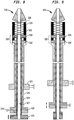
- FIG. 9 shows another exemplary transfemoral delivery device 610 for a collapsible prosthetic heart valve according to the invention.
- the structure and function of the delivery device 610 is similar to the structure and function of the delivery device 510 described above in all respects, except that the pusher 632 is longitudinally slidable relative to the holder 634 to allow a user to capture the stent portion of a prosthetic valve in the retainer 630, rather than having the holder slidable relative to the pusher.
- the pusher, the holder, or both components are configured to be slidable or fixed in a given embodiment may depend on how the respective hubs are attached to an operating handle (not shown).
- the stent portion of a prosthetic valve may be captured between the pusher and holder in a similar manner regardless of whether the pusher, the holder, or both components are configured to be slidable.
- FIGS. 10A and 10B yet another exemplary transfemoral delivery device 710 for a collapsible prosthetic heart valve according to the invention is shown.
- the delivery device 710 is similar to the delivery devices 510 and 610 described above with reference to FIGS. 8 and 9 , respectively, except that, rather than a plurality of discrete recesses, the pusher 732 includes a single recess 740 having an annular wall 741 extending continuously around the entire circumference thereof.
- the V-shaped junctions of the stent portion of the valve may be retained by the annular wall 741 such that the V-shaped junctions do not splay radially outward.
- the presence of the annular wall 741 in the pusher 732 may make it easier for the pusher 732 to retain the proximal end of a valve during loading of the valve into the delivery device 710.
- the pusher 732, the holder 734, or both components may be slidable or fixed relative to one another.
- the ribs in the holder 734 are not shown in FIG. 10A , the holder may have any of the rib configurations disclosed herein.
- a retainer 830 in accordance with another embodiment of the invention is shown in FIG. 11 .
- the retainer 830 is similar to the retainers 230, 530, 630, and 730 having a movable pusher and/or holder as described above, except that the ribs 850 extend proximally from a conical end 836 attached to the holder 834, rather than extending radially outward from an outer surface of the holder.
- the recesses in the pusher 832 are not visible in the particular cross-section shown in FIG. 11
- the holder may have recesses extending proximally from the retention edge 833 that are adapted to receive V-shaped junctions of the stent portion of a collapsible prosthetic valve.
- the pusher 832, the holder 834, or both components may be slidable relative to one another or fixed.
- an exemplary transapical delivery device 910 for a collapsible prosthetic heart valve 906 has a catheter assembly 916 for delivering the heart valve to and deploying the heart valve at a target location.
- the delivery device 910 extends from a proximal end 912 to a distal end 914.
- the catheter assembly 916 is adapted to receive a collapsible prosthetic heart valve in an assembled condition in a compartment 923 defined around a support shaft 928 and covered by a distal sheath 924.
- the support shaft 928 extends from a holder 934 fixed at the distal end of the support shaft to a retainer 911 fixed at the proximal end of the support shaft.
- the retainer 911 is connected to an outer shaft 922 having a hub 921 on its proximal end.
- the holder 934 and a pusher 932 are adapted to hold a collapsible prosthetic valve in the compartment 923 defined around the support shaft 928.
- the pusher 932 may be affixed to a pusher shaft 929 that extends through the support shaft 928 and the outer shaft 922 to a hub 925.
- An inner shaft 926 may extend through the pusher shaft 929 from a hub 920 at its proximal end to a connection to an atraumatic tip 931 at the distal end 914 of the delivery device 910.
- the distal sheath 924 surrounds compartment 923 and is slidable relative to the support shaft 928 such that it can selectively cover or uncover a collapsed prosthetic valve 906 positioned in the compartment.
- the distal sheath 924 is affixed at its distal end to the tip 931.
- the proximal end 915 of the distal sheath 924 may abut a conical surface 917 of the retainer 911 when the distal sheath fully covers the compartment 923, as shown in FIG. 12 , and is spaced apart from the conical surface 917 when the compartment 923 is at least partially uncovered.
- the pusher 932 and/or the holder 934 may slide relative to one another to capture the distal end of the stent portion of the valve 906 therebetween.
- the recesses in the pusher 932 and the ribs on the holder 934 are not shown in FIG. 12
- the pusher and the holder may have any of the recess and rib configurations disclosed herein.
- a user may load a valve 906 in the compartment 923 by capturing the V-shaped junctions of the stent portion of the valve between the recesses of the pusher 932 and the ribs of the holder 934 by sliding the pusher and/or the holder longitudinally towards one another.
- the delivery device 910 may include a locking pin 919 adapted, in a locked position, to temporarily affix the outer shaft 922 (and with it, the support shaft 928) to the pusher shaft 929 and thereby fix the relative positions of the pusher 932 and the holder 934. With the distal end of the stent portion of the valve 906 captured between the pusher and the holder, the user may move the locking pin 919 to a locked position to fix the relative positions of the pusher and the holder.
- the user may first withdraw the distal sheath 924 from around the compartment 923 by sliding the inner shaft 926 distally relative to the outer shaft 922 and the pusher shaft 929. Subsequently, the user may move the locking pin 919 to an unlocked position, and may slide the pusher 932 and the holder 934 longitudinally away from one another to unclamp the valve 906 from within the retainer 930 so that the valve can self-expand and thereby become released from the delivery device 910.
- the retainer 1030 is adapted to retain and align the stent portion of a conventional prosthetic valve, such as the stent portion 6 shown in FIG. 1 .
- the retainer 1030 may be incorporated either in a transfemoral delivery device, such as the delivery device 10 described above, with the valve extending distally from the retainer, or in a transapical delivery device, such as the delivery device 910 described above, with the valve extending proximally from the retainer.
- the retainer 1030 includes a retention portion 1032 affixed to an inner shaft 1026, the retention portion including a plurality of acceptances 1035 adapted to receive retention members of a conventional valve, such as the retention members 7 shown in FIG. 1 .
- the retainer 1030 also includes a spacer portion 1034 affixed to the retention portion 1032, the spacer portion including a plurality of ribs 1050 extending in a longitudinal direction, each adjacent pair of ribs defining a channel 1052 therebetween.
- the ribs 1050 preferably are spaced uniformly in a circumferential direction around the spacer portion 1034.
- a user may insert the retention members of the valve into the acceptances 1035, and the V-shaped junctions at the aortic end of the stent into respective channels 1052.
- the channels 1052 that are longitudinally aligned with an acceptance 1035 can receive the V-shaped junction aligned in the longitudinal direction with a retention member.
- the stent portion of a conventional prosthetic valve can become twisted during delivery of the valve to a desired location in a patient, and the stent struts can bind against the distal sheath covering the valve, potentially deforming or damaging the struts and/or increasing the force required to unsheathe the valve.
- the retainer 1030 can keep the V-shaped junctions of the stent struts aligned during delivery of the valve within a patient, thereby preventing damage to the valve and minimizing the force needed for unsheathing and deployment.
- retainer embodiments have been described here in connection with retaining for deployment a prosthetic valve having a collapsible stent structure, all of the retainer embodiments may be used for other purposes.
- the various embodiments of retainers may be used to retain conventional collapsible stents that do not contain a valve structure.
- the invention herein has been described with reference to particular embodiments in which the annulus end of a prosthetic valve is deployed first, it is to be understood that the invention contemplates embodiments in which the aortic end of a valve is deployed first.
- the annulus end of the stent portion of the valve may be engaged with a retainer, while the aortic end of the stent may be remote from the retainer and may be unsheathed first.
- the present invention enjoys wide industrial applicability including, but not limited to, delivery devices for collapsible prosthetic heart valves and methods of delivering collapsible prosthetic heart valves.
Landscapes
- Health & Medical Sciences (AREA)
- Cardiology (AREA)
- Engineering & Computer Science (AREA)
- Biomedical Technology (AREA)
- Heart & Thoracic Surgery (AREA)
- Transplantation (AREA)
- Oral & Maxillofacial Surgery (AREA)
- Vascular Medicine (AREA)
- Life Sciences & Earth Sciences (AREA)
- Animal Behavior & Ethology (AREA)
- General Health & Medical Sciences (AREA)
- Public Health (AREA)
- Veterinary Medicine (AREA)
- Prostheses (AREA)
Claims (10)
- Dispositif d'acheminement (10 ; 510 ; 610 ; 710 ; 910) pour une valve cardiaque prosthétique repliable (506 ; 906), le dispositif d'acheminement comprenant :un ensemble sonde (16 ; 916) comprenant une tige principale (26 ; 227 ; 527 ; 928) autour de laquelle est défini un compartiment (23; 523 ; 923), le compartiment étant adapté à recevoir la valve à l'état assemblé, l'ensemble sonde comprenant en outre une gaine distale (24 ; 524 ; 924) prévue pour couvrir et découvrir sélectivement le compartiment et la valve, la gaine distale s'étendant autour de la tige principale au moins lorsque la gaine distale recouvre le compartiment ; etun élément de retenue (230 ; 530; 730 ; 830) comprenant :un poussoir (232 ; 432 ; 532 ; 632 ; 732 ; 832 ; 932) ayant au moins un évidement (240 ; 440 ; 440a ; 740) dans un bord de retenue de celui-ci, l'évidement étant adapté pour recevoir une jonction au niveau d'une extrémité d'une partie de stent de la valve ; etun support (234 ; 334 ; 434 ; 534 ; 634 ; 734 ; 834 ; 934) ayant au moins une nervure allongée (250 ; 350 ; 450 ; 450a ; 850) adaptée à s'ajuster dans une ouverture cellulaire dans la partie de stent de la valve, caractérisé en ce quele poussoir peut coulisser relativement au support le long d'un axe longitudinal du dispositif d'acheminement et/ou le support peut coulisser relativement au poussoir le long de l'axe longitudinal du dispositif d'acheminement.
- Dispositif d'acheminement selon la revendication 1, dans lequel l'au moins un évidement est façonné de façon à sensiblement correspondre à la forme des surfaces de la jonction tournées vers l'extérieur.
- Dispositif d'acheminement selon la revendication 1, dans lequel l'au moins une nervure a une largeur dans une direction circonférentielle, une extrémité de la nervure relativement proche du poussoir ayant une première largeur et une extrémité de la nervure relativement éloignée du poussoir ayant une seconde largeur supérieure à la première largeur, de telle sorte que la nervure est façonnée pour sensiblement correspondre à la forme de surfaces, tournées vers l'intérieur, de l'ouverture cellulaire contactée par la nervure.
- Dispositif d'acheminement selon la revendication 1, dans lequel l'au moins une nervure a une forme en coupe dans une direction circonférentielle qui comprend une encoche.
- Dispositif d'acheminement selon la revendication 1, dans lequel l'au moins un évidement a une forme en coupe dans une direction circonférentielle qui comprend une encoche.
- Dispositif d'acheminement selon la revendication 1, dans lequel l'au moins un évidement est un canal annulaire continu formé dans le bord de retenue du poussoir adjacent à une circonférence du poussoir.
- Dispositif d'acheminement selon la revendication 1, dans lequel la tige principale (229) est fixée au support, le dispositif d'acheminement comprenant en outre une tige poussoir (226) fixée au poussoir et s'étendant le long d'un axe longitudinal du dispositif d'acheminement hors de la tige principale.
- Dispositif d'acheminement selon la revendication 7, comprenant en outre une goupille d'arrêt (519) adaptée à temporairement fixer la tige principale à la tige poussoir de manière à ce que la gaine distale puisse coulisser le long de l'axe longitudinal relativement à la tige principale fixée et à la tige poussoir.
- Dispositif d'acheminement selon la revendication 1, dans lequel la tige principale (928) est fixée au support, le dispositif d'acheminement comprenant en outre une tige poussoir (929) fixée au poussoir et s'étendant le long d'un axe longitudinal du dispositif d'acheminement à l'intérieur de la tige principale.
- Dispositif d'acheminement selon la revendication 9, comprenant en outre une goupille d'arrêt (919) adaptée à temporairement fixer la tige principale à la tige poussoir de manière à ce que la gaine distale puisse coulisser le long de l'axe longitudinal relativement à la tige principale fixée et à la tige poussoir.
Applications Claiming Priority (2)
| Application Number | Priority Date | Filing Date | Title |
|---|---|---|---|
| US38401410P | 2010-09-17 | 2010-09-17 | |
| PCT/US2011/001596 WO2012036740A2 (fr) | 2010-09-17 | 2011-09-16 | Eléments de retenue pour systèmes d'acheminement de valves cardiaques à travers des sondes |
Publications (2)
| Publication Number | Publication Date |
|---|---|
| EP2616006A2 EP2616006A2 (fr) | 2013-07-24 |
| EP2616006B1 true EP2616006B1 (fr) | 2018-08-29 |
Family
ID=44736024
Family Applications (1)
| Application Number | Title | Priority Date | Filing Date |
|---|---|---|---|
| EP11764364.3A Active EP2616006B1 (fr) | 2010-09-17 | 2011-09-16 | Eléments de retenue pour systèmes d'acheminement de valves cardiaques à travers des sondes |
Country Status (7)
| Country | Link |
|---|---|
| US (2) | US9439795B2 (fr) |
| EP (1) | EP2616006B1 (fr) |
| JP (1) | JP2013540481A (fr) |
| AU (1) | AU2011302639B2 (fr) |
| BR (1) | BR112013006302A2 (fr) |
| CR (1) | CR20130164A (fr) |
| WO (1) | WO2012036740A2 (fr) |
Cited By (16)
| Publication number | Priority date | Publication date | Assignee | Title |
|---|---|---|---|---|
| US10856984B2 (en) | 2017-08-25 | 2020-12-08 | Neovasc Tiara Inc. | Sequentially deployed transcatheter mitral valve prosthesis |
| US10940001B2 (en) | 2012-05-30 | 2021-03-09 | Neovasc Tiara Inc. | Methods and apparatus for loading a prosthesis onto a delivery system |
| US11311376B2 (en) | 2019-06-20 | 2022-04-26 | Neovase Tiara Inc. | Low profile prosthetic mitral valve |
| US11357622B2 (en) | 2016-01-29 | 2022-06-14 | Neovase Tiara Inc. | Prosthetic valve for avoiding obstruction of outflow |
| US11389291B2 (en) | 2013-04-04 | 2022-07-19 | Neovase Tiara Inc. | Methods and apparatus for delivering a prosthetic valve to a beating heart |
| US11413139B2 (en) | 2011-11-23 | 2022-08-16 | Neovasc Tiara Inc. | Sequentially deployed transcatheter mitral valve prosthesis |
| US11419720B2 (en) | 2010-05-05 | 2022-08-23 | Neovasc Tiara Inc. | Transcatheter mitral valve prosthesis |
| US11464631B2 (en) | 2016-11-21 | 2022-10-11 | Neovasc Tiara Inc. | Methods and systems for rapid retraction of a transcatheter heart valve delivery system |
| US11491006B2 (en) | 2019-04-10 | 2022-11-08 | Neovasc Tiara Inc. | Prosthetic valve with natural blood flow |
| US11497602B2 (en) | 2012-02-14 | 2022-11-15 | Neovasc Tiara Inc. | Methods and apparatus for engaging a valve prosthesis with tissue |
| US11602429B2 (en) | 2019-04-01 | 2023-03-14 | Neovasc Tiara Inc. | Controllably deployable prosthetic valve |
| US11737872B2 (en) | 2018-11-08 | 2023-08-29 | Neovasc Tiara Inc. | Ventricular deployment of a transcatheter mitral valve prosthesis |
| US11779742B2 (en) | 2019-05-20 | 2023-10-10 | Neovasc Tiara Inc. | Introducer with hemostasis mechanism |
| US11998447B2 (en) | 2019-03-08 | 2024-06-04 | Neovasc Tiara Inc. | Retrievable prosthesis delivery system |
| US12109111B2 (en) | 2015-12-15 | 2024-10-08 | Neovasc Tiara Inc. | Transseptal delivery system |
| US12138159B2 (en) | 2022-10-13 | 2024-11-12 | Neovasc Tiara Inc. | Methods and apparatus for engaging a valve prosthesis with tissue |
Families Citing this family (93)
| Publication number | Priority date | Publication date | Assignee | Title |
|---|---|---|---|---|
| US8603160B2 (en) | 2003-12-23 | 2013-12-10 | Sadra Medical, Inc. | Method of using a retrievable heart valve anchor with a sheath |
| US8828078B2 (en) | 2003-12-23 | 2014-09-09 | Sadra Medical, Inc. | Methods and apparatus for endovascular heart valve replacement comprising tissue grasping elements |
| US7381219B2 (en) | 2003-12-23 | 2008-06-03 | Sadra Medical, Inc. | Low profile heart valve and delivery system |
| US8840663B2 (en) | 2003-12-23 | 2014-09-23 | Sadra Medical, Inc. | Repositionable heart valve method |
| US20120041550A1 (en) | 2003-12-23 | 2012-02-16 | Sadra Medical, Inc. | Methods and Apparatus for Endovascular Heart Valve Replacement Comprising Tissue Grasping Elements |
| US11278398B2 (en) | 2003-12-23 | 2022-03-22 | Boston Scientific Scimed, Inc. | Methods and apparatus for endovascular heart valve replacement comprising tissue grasping elements |
| US20050137687A1 (en) | 2003-12-23 | 2005-06-23 | Sadra Medical | Heart valve anchor and method |
| US7959666B2 (en) * | 2003-12-23 | 2011-06-14 | Sadra Medical, Inc. | Methods and apparatus for endovascularly replacing a heart valve |
| US9526609B2 (en) | 2003-12-23 | 2016-12-27 | Boston Scientific Scimed, Inc. | Methods and apparatus for endovascularly replacing a patient's heart valve |
| DE102005003632A1 (de) | 2005-01-20 | 2006-08-17 | Fraunhofer-Gesellschaft zur Förderung der angewandten Forschung e.V. | Katheter für die transvaskuläre Implantation von Herzklappenprothesen |
| US20070213813A1 (en) | 2005-12-22 | 2007-09-13 | Symetis Sa | Stent-valves for valve replacement and associated methods and systems for surgery |
| CN101415379B (zh) | 2006-02-14 | 2012-06-20 | 萨德拉医学公司 | 用于输送医疗植入物的系统 |
| US7896915B2 (en) | 2007-04-13 | 2011-03-01 | Jenavalve Technology, Inc. | Medical device for treating a heart valve insufficiency |
| ES2903231T3 (es) | 2008-02-26 | 2022-03-31 | Jenavalve Tech Inc | Stent para el posicionamiento y anclaje de una prótesis valvular en un sitio de implantación en el corazón de un paciente |
| US9044318B2 (en) | 2008-02-26 | 2015-06-02 | Jenavalve Technology Gmbh | Stent for the positioning and anchoring of a valvular prosthesis |
| EP2340075B1 (fr) | 2008-10-10 | 2013-03-06 | Sadra Medical, Inc. | Dispositifs médicaux et systèmes de délivrance destinés à délivrer des dispositifs médicaux |
| US8870950B2 (en) | 2009-12-08 | 2014-10-28 | Mitral Tech Ltd. | Rotation-based anchoring of an implant |
| WO2011111047A2 (fr) | 2010-03-10 | 2011-09-15 | Mitraltech Ltd. | Valvule mitrale prothétique avec ancrages de tissus |
| CN103002833B (zh) | 2010-05-25 | 2016-05-11 | 耶拿阀门科技公司 | 人工心脏瓣及包括人工心脏瓣和支架的经导管输送的内假体 |
| US9387077B2 (en) * | 2010-05-27 | 2016-07-12 | Medtronic Vascular Galway | Catheter assembly with prosthesis crimping and prosthesis retaining accessories |
| US11653910B2 (en) | 2010-07-21 | 2023-05-23 | Cardiovalve Ltd. | Helical anchor implantation |
| US9763657B2 (en) | 2010-07-21 | 2017-09-19 | Mitraltech Ltd. | Techniques for percutaneous mitral valve replacement and sealing |
| WO2012023980A1 (fr) | 2010-08-17 | 2012-02-23 | St. Jude Medical, Inc. | Manchon pour faciliter le déplacement d'un cathéter pour abord transfémoral |
| CN106073946B (zh) | 2010-09-10 | 2022-01-04 | 西美蒂斯股份公司 | 瓣膜置换装置、用于瓣膜置换装置的递送装置以及瓣膜置换装置的生产方法 |
| BR112013006302A2 (pt) | 2010-09-17 | 2016-06-07 | St Jude Medical Cardiology Div | dispositivo de colocação para uma válvula cardíaca protética colapsável, e, método para colocar uma válvula cardíaca protética colapsável |
| US9144494B2 (en) * | 2011-05-12 | 2015-09-29 | Medtronic, Inc. | Delivery catheter system with micro and macro movement control |
| CA2835893C (fr) | 2011-07-12 | 2019-03-19 | Boston Scientific Scimed, Inc. | Systeme de couplage pour dispositifs medicaux |
| WO2013016107A1 (fr) | 2011-07-28 | 2013-01-31 | St. Jude Medical, Inc. | Marqueur radio-opaque extensible pour une implantation de valvule sigmoïde transcathéter |
| WO2013021374A2 (fr) | 2011-08-05 | 2013-02-14 | Mitraltech Ltd. | Techniques pour le remplacement et la fixation percutanés d'une valvule mitrale |
| US20140324164A1 (en) | 2011-08-05 | 2014-10-30 | Mitraltech Ltd. | Techniques for percutaneous mitral valve replacement and sealing |
| US8852272B2 (en) | 2011-08-05 | 2014-10-07 | Mitraltech Ltd. | Techniques for percutaneous mitral valve replacement and sealing |
| EP2739214B1 (fr) | 2011-08-05 | 2018-10-10 | Cardiovalve Ltd | Remplacement et fixation percutanés d'une valvule mitrale |
| GB2500881A (en) * | 2012-03-30 | 2013-10-09 | Cook Medical Technologies Llc | Stent holding structure for introducers |
| US9480561B2 (en) | 2012-06-26 | 2016-11-01 | St. Jude Medical, Cardiology Division, Inc. | Apparatus and method for aortic protection and TAVI planar alignment |
| US9918837B2 (en) | 2012-06-29 | 2018-03-20 | St. Jude Medical, Cardiology Division, Inc. | System to assist in the release of a collapsible stent from a delivery device |
| JP6057584B2 (ja) * | 2012-07-24 | 2017-01-11 | 株式会社カネカ | 自己拡張型ステントデリバリーシステムとその製造方法 |
| US9687373B2 (en) * | 2012-12-21 | 2017-06-27 | Cook Medical Technologies Llc | Systems and methods for securing and releasing a portion of a stent |
| CN103083122B (zh) * | 2013-01-21 | 2015-11-04 | 北京华脉泰科医疗器械有限公司 | 一种覆膜支架的固定装置 |
| EP4166111A1 (fr) | 2013-01-24 | 2023-04-19 | Cardiovalve Ltd. | Valvules prothétiques à ancrage ventriculaire |
| CN103126739B (zh) * | 2013-01-31 | 2016-05-04 | 北京华脉泰科医疗器械有限公司 | 一种覆膜支架的输送装置 |
| DE102013104565B3 (de) * | 2013-05-03 | 2014-10-16 | Jotec Gmbh | Pusher-Baugruppe für ein Einführsystem für ein selbstexpandierendes Gefäßimplantat sowie ein entsprechendes Einführsystem |
| US9867694B2 (en) | 2013-08-30 | 2018-01-16 | Jenavalve Technology Inc. | Radially collapsible frame for a prosthetic valve and method for manufacturing such a frame |
| EP3174502B1 (fr) | 2014-07-30 | 2022-04-06 | Cardiovalve Ltd | Appareil d'implantation de prothèse valvulaire articulable |
| DE202014104330U1 (de) * | 2014-09-12 | 2015-12-16 | Pfm Medical Ag | Vorrichtung zum Einsetzen eines medizinischen Implantates in einen menschlichen oder tierischen Körper |
| US9433520B2 (en) | 2015-01-29 | 2016-09-06 | Intact Vascular, Inc. | Delivery device and method of delivery |
| US9375336B1 (en) | 2015-01-29 | 2016-06-28 | Intact Vascular, Inc. | Delivery device and method of delivery |
| CN110141399B (zh) | 2015-02-05 | 2021-07-27 | 卡迪尔维尔福股份有限公司 | 带有轴向滑动框架的人工瓣膜 |
| US9974651B2 (en) | 2015-02-05 | 2018-05-22 | Mitral Tech Ltd. | Prosthetic valve with axially-sliding frames |
| EP3270825B1 (fr) | 2015-03-20 | 2020-04-22 | JenaValve Technology, Inc. | Système de pose de prothèse de valvule cardiaque |
| US10376363B2 (en) * | 2015-04-30 | 2019-08-13 | Edwards Lifesciences Cardiaq Llc | Replacement mitral valve, delivery system for replacement mitral valve and methods of use |
| CN107530168B (zh) | 2015-05-01 | 2020-06-09 | 耶拿阀门科技股份有限公司 | 在心脏瓣膜替换中具有降低的起搏器比例的装置和方法 |
| CN106913408B (zh) * | 2015-12-28 | 2018-10-26 | 先健科技(深圳)有限公司 | 输送系统及管腔支架系统 |
| US10993824B2 (en) | 2016-01-01 | 2021-05-04 | Intact Vascular, Inc. | Delivery device and method of delivery |
| US10531866B2 (en) | 2016-02-16 | 2020-01-14 | Cardiovalve Ltd. | Techniques for providing a replacement valve and transseptal communication |
| EP3213714A1 (fr) * | 2016-03-03 | 2017-09-06 | Biotronik AG | Catheter de largage et systeme de catheter |
| JP6724490B2 (ja) * | 2016-03-31 | 2020-07-15 | 日本ゼオン株式会社 | ステントデリバリーシステム |
| US10667907B2 (en) | 2016-05-13 | 2020-06-02 | St. Jude Medical, Cardiology Division, Inc. | Systems and methods for device implantation |
| WO2017195125A1 (fr) | 2016-05-13 | 2017-11-16 | Jenavalve Technology, Inc. | Système d'implantation de prothèse de valve cardiaque et procédé pour la pose d'une prothèse de valve cardiaque avec une gaine d'introduction et système de chargement |
| US10201416B2 (en) | 2016-05-16 | 2019-02-12 | Boston Scientific Scimed, Inc. | Replacement heart valve implant with invertible leaflets |
| US20190231525A1 (en) * | 2016-08-01 | 2019-08-01 | Mitraltech Ltd. | Minimally-invasive delivery systems |
| US10856975B2 (en) | 2016-08-10 | 2020-12-08 | Cardiovalve Ltd. | Prosthetic valve with concentric frames |
| US10376396B2 (en) | 2017-01-19 | 2019-08-13 | Covidien Lp | Coupling units for medical device delivery systems |
| US10653523B2 (en) | 2017-01-19 | 2020-05-19 | 4C Medical Technologies, Inc. | Systems, methods and devices for delivery systems, methods and devices for implanting prosthetic heart valves |
| US10561495B2 (en) | 2017-01-24 | 2020-02-18 | 4C Medical Technologies, Inc. | Systems, methods and devices for two-step delivery and implantation of prosthetic heart valve |
| WO2018138658A1 (fr) | 2017-01-27 | 2018-08-02 | Jenavalve Technology, Inc. | Mimétisme de valve cardiaque |
| US12029647B2 (en) | 2017-03-07 | 2024-07-09 | 4C Medical Technologies, Inc. | Systems, methods and devices for prosthetic heart valve with single valve leaflet |
| US12036113B2 (en) | 2017-06-14 | 2024-07-16 | 4C Medical Technologies, Inc. | Delivery of heart chamber prosthetic valve implant |
| CN110996853B (zh) | 2017-06-30 | 2023-01-10 | 爱德华兹生命科学公司 | 经导管瓣膜的对接站 |
| US11660218B2 (en) | 2017-07-26 | 2023-05-30 | Intact Vascular, Inc. | Delivery device and method of delivery |
| US12064347B2 (en) | 2017-08-03 | 2024-08-20 | Cardiovalve Ltd. | Prosthetic heart valve |
| US10575948B2 (en) | 2017-08-03 | 2020-03-03 | Cardiovalve Ltd. | Prosthetic heart valve |
| US11246704B2 (en) | 2017-08-03 | 2022-02-15 | Cardiovalve Ltd. | Prosthetic heart valve |
| US10537426B2 (en) | 2017-08-03 | 2020-01-21 | Cardiovalve Ltd. | Prosthetic heart valve |
| US10888421B2 (en) | 2017-09-19 | 2021-01-12 | Cardiovalve Ltd. | Prosthetic heart valve with pouch |
| US11793633B2 (en) | 2017-08-03 | 2023-10-24 | Cardiovalve Ltd. | Prosthetic heart valve |
| US11819405B2 (en) | 2017-09-19 | 2023-11-21 | Cardiovalve Ltd. | Prosthetic valve with inflatable cuff configured for radial extension |
| US9895226B1 (en) | 2017-10-19 | 2018-02-20 | Mitral Tech Ltd. | Techniques for use with prosthetic valve leaflets |
| GB201720803D0 (en) | 2017-12-13 | 2018-01-24 | Mitraltech Ltd | Prosthetic Valve and delivery tool therefor |
| GB201800399D0 (en) | 2018-01-10 | 2018-02-21 | Mitraltech Ltd | Temperature-control during crimping of an implant |
| WO2019147846A2 (fr) | 2018-01-25 | 2019-08-01 | Edwards Lifesciences Corporation | Système de distribution pour recapture de valvule de remplacement assistée et post-déploiement de repositionnement |
| US10932931B2 (en) * | 2018-03-13 | 2021-03-02 | Medtronic Vascular, Inc. | Medical device delivery system including a support member |
| US10786377B2 (en) * | 2018-04-12 | 2020-09-29 | Covidien Lp | Medical device delivery |
| US11413176B2 (en) | 2018-04-12 | 2022-08-16 | Covidien Lp | Medical device delivery |
| US11071637B2 (en) | 2018-04-12 | 2021-07-27 | Covidien Lp | Medical device delivery |
| US11123209B2 (en) | 2018-04-12 | 2021-09-21 | Covidien Lp | Medical device delivery |
| US11857441B2 (en) | 2018-09-04 | 2024-01-02 | 4C Medical Technologies, Inc. | Stent loading device |
| US11413174B2 (en) | 2019-06-26 | 2022-08-16 | Covidien Lp | Core assembly for medical device delivery systems |
| US12133797B2 (en) | 2020-01-31 | 2024-11-05 | 4C Medical Technologies, Inc. | Prosthetic heart valve delivery system: paddle attachment feature |
| US11931253B2 (en) | 2020-01-31 | 2024-03-19 | 4C Medical Technologies, Inc. | Prosthetic heart valve delivery system: ball-slide attachment |
| US12053375B2 (en) | 2020-03-05 | 2024-08-06 | 4C Medical Technologies, Inc. | Prosthetic mitral valve with improved atrial and/or annular apposition and paravalvular leakage mitigation |
| US11992403B2 (en) | 2020-03-06 | 2024-05-28 | 4C Medical Technologies, Inc. | Devices, systems and methods for improving recapture of prosthetic heart valve device with stent frame having valve support with inwardly stent cells |
| US12109137B2 (en) | 2021-07-30 | 2024-10-08 | Covidien Lp | Medical device delivery |
| US11944558B2 (en) | 2021-08-05 | 2024-04-02 | Covidien Lp | Medical device delivery devices, systems, and methods |
Family Cites Families (144)
| Publication number | Priority date | Publication date | Assignee | Title |
|---|---|---|---|---|
| SE433445B (sv) | 1981-04-16 | 1984-05-28 | Erik Gustav Percy Nordqvist | Urinkateter |
| US4423730A (en) | 1982-03-01 | 1984-01-03 | Shelhigh Inc. | Atriotomy button and implantation device |
| US4471777A (en) * | 1983-03-30 | 1984-09-18 | Mccorkle Jr Charles E | Endocardial lead extraction apparatus and method |
| US4546759A (en) | 1983-07-29 | 1985-10-15 | Mladen Solar | Method and apparatus for assisting human heart function |
| US5190546A (en) | 1983-10-14 | 1993-03-02 | Raychem Corporation | Medical devices incorporating SIM alloy elements |
| US5120299A (en) | 1987-05-22 | 1992-06-09 | Kontron Instruments, Inc. | Intra-aortic balloon assembly with hemostasis device |
| US5201901A (en) | 1987-10-08 | 1993-04-13 | Terumo Kabushiki Kaisha | Expansion unit and apparatus for expanding tubular organ lumen |
| US5090958A (en) | 1988-11-23 | 1992-02-25 | Harvinder Sahota | Balloon catheters |
| US5411552A (en) | 1990-05-18 | 1995-05-02 | Andersen; Henning R. | Valve prothesis for implantation in the body and a catheter for implanting such valve prothesis |
| US5795325A (en) | 1991-07-16 | 1998-08-18 | Heartport, Inc. | Methods and apparatus for anchoring an occluding member |
| US5766151A (en) | 1991-07-16 | 1998-06-16 | Heartport, Inc. | Endovascular system for arresting the heart |
| US5334160A (en) | 1992-05-04 | 1994-08-02 | Scimed Life Systems, Inc. | Intravascular catheter with sleeve and method for use thereof |
| US5797960A (en) | 1993-02-22 | 1998-08-25 | Stevens; John H. | Method and apparatus for thoracoscopic intracardiac procedures |
| EP0657147B1 (fr) | 1993-11-04 | 1999-08-04 | C.R. Bard, Inc. | Prothèse vasculaire non migrante |
| AU691854B2 (en) | 1993-12-03 | 1998-05-28 | Edwards Lifesciences Ag | Cardiopulmonary bypass system for closed-chest intervention |
| JP3713048B2 (ja) | 1994-12-27 | 2005-11-02 | アドバンスト・カーディオバスキュラー・システムズ・インコーポレイテッド | 補強された長円形状の横断面を備えたカテーテル |
| US6312407B1 (en) | 1995-06-05 | 2001-11-06 | Medtronic Percusurge, Inc. | Occlusion of a vessel |
| US6673040B1 (en) | 1996-04-16 | 2004-01-06 | Cardeon Corporation | System and methods for catheter procedures with circulatory support in high risk patients |
| US5797952A (en) | 1996-06-21 | 1998-08-25 | Localmed, Inc. | System and method for delivering helical stents |
| US6077295A (en) | 1996-07-15 | 2000-06-20 | Advanced Cardiovascular Systems, Inc. | Self-expanding stent delivery system |
| US5968068A (en) | 1996-09-12 | 1999-10-19 | Baxter International Inc. | Endovascular delivery system |
| US5868755A (en) | 1997-01-16 | 1999-02-09 | Atrion Medical Products, Inc. | Sheath retractor mechanism and method |
| US5827324A (en) | 1997-03-06 | 1998-10-27 | Scimed Life Systems, Inc. | Distal protection device |
| GB9706766D0 (en) | 1997-04-03 | 1997-05-21 | Sulzer Vascutek Ltd | Endovascular prostheses |
| US6361545B1 (en) | 1997-09-26 | 2002-03-26 | Cardeon Corporation | Perfusion filter catheter |
| DE69818302D1 (de) | 1997-12-15 | 2003-10-23 | Cardeon Corp | Perfusionsverbindungsvorrichtung |
| US6776791B1 (en) | 1998-04-01 | 2004-08-17 | Endovascular Technologies, Inc. | Stent and method and device for packing of same |
| US6190357B1 (en) | 1998-04-21 | 2001-02-20 | Cardiothoracic Systems, Inc. | Expandable cannula for performing cardiopulmonary bypass and method for using same |
| US5980533A (en) * | 1998-06-09 | 1999-11-09 | Scimed Life Systems, Inc. | Stent delivery system |
| US6231588B1 (en) | 1998-08-04 | 2001-05-15 | Percusurge, Inc. | Low profile catheter for angioplasty and occlusion |
| US6051014A (en) | 1998-10-13 | 2000-04-18 | Embol-X, Inc. | Percutaneous filtration catheter for valve repair surgery and methods of use |
| US6214036B1 (en) | 1998-11-09 | 2001-04-10 | Cordis Corporation | Stent which is easily recaptured and repositioned within the body |
| US6146415A (en) | 1999-05-07 | 2000-11-14 | Advanced Cardiovascular Systems, Inc. | Stent delivery system |
| AU5280600A (en) | 1999-05-20 | 2000-12-12 | Scimed Life Systems, Inc. | Stent delivery system with nested stabilizer and method of loading and using same |
| US6375668B1 (en) | 1999-06-02 | 2002-04-23 | Hanson S. Gifford | Devices and methods for treating vascular malformations |
| US6592612B1 (en) | 2000-05-04 | 2003-07-15 | Cardeon Corporation | Method and apparatus for providing heat exchange within a catheter body |
| DE10026307A1 (de) | 2000-05-26 | 2001-11-29 | Variomed Ag Balzers | Stent,Positionierelement und Einführkatheter |
| US7381198B2 (en) | 2000-08-23 | 2008-06-03 | Revascular Therapeutics, Inc. | Steerable distal support system |
| US20060142848A1 (en) | 2000-09-12 | 2006-06-29 | Shlomo Gabbay | Extra-anatomic aortic valve placement |
| US6482228B1 (en) | 2000-11-14 | 2002-11-19 | Troy R. Norred | Percutaneous aortic valve replacement |
| US6623518B2 (en) * | 2001-02-26 | 2003-09-23 | Ev3 Peripheral, Inc. | Implant delivery system with interlock |
| US6605056B2 (en) | 2001-07-11 | 2003-08-12 | Scimed Life Systems, Inc. | Conformable balloon |
| DE60212006T2 (de) | 2001-07-13 | 2007-04-19 | B. Braun Medical Sas | Vaskuläres Schutzsystem und Angioplastievorrichtung |
| FR2828091B1 (fr) | 2001-07-31 | 2003-11-21 | Seguin Jacques | Ensemble permettant la mise en place d'une valve prothetique dans un conduit corporel |
| US20060106415A1 (en) | 2004-11-12 | 2006-05-18 | Shlomo Gabbay | Apparatus to facilitate implantation |
| US7235095B2 (en) * | 2002-02-22 | 2007-06-26 | Scimed Life Systems, Inc. | Method and system for deploying multi-part endoluminal devices |
| US8721713B2 (en) | 2002-04-23 | 2014-05-13 | Medtronic, Inc. | System for implanting a replacement valve |
| US7264632B2 (en) | 2002-06-07 | 2007-09-04 | Medtronic Vascular, Inc. | Controlled deployment delivery system |
| US6814746B2 (en) | 2002-11-01 | 2004-11-09 | Ev3 Peripheral, Inc. | Implant delivery system with marker interlock |
| WO2004071352A1 (fr) | 2003-02-14 | 2004-08-26 | Salviac Limited | Systeme d'amenee et de deploiement de stent |
| US7771463B2 (en) | 2003-03-26 | 2010-08-10 | Ton Dai T | Twist-down implant delivery technologies |
| US7473271B2 (en) | 2003-04-11 | 2009-01-06 | Boston Scientific Scimed, Inc. | Stent delivery system with securement and deployment accuracy |
| US20040267348A1 (en) | 2003-04-11 | 2004-12-30 | Gunderson Richard C. | Medical device delivery systems |
| US7235093B2 (en) | 2003-05-20 | 2007-06-26 | Boston Scientific Scimed, Inc. | Mechanism to improve stent securement |
| US7470282B2 (en) | 2003-06-30 | 2008-12-30 | Boston Scientific Scimed, Inc. | Stent grip and system for use therewith |
| US7241276B2 (en) | 2003-08-06 | 2007-07-10 | Trivascular, Inc. | Passive hemostatic sheath valve |
| US7763063B2 (en) | 2003-09-03 | 2010-07-27 | Bolton Medical, Inc. | Self-aligning stent graft delivery system, kit, and method |
| US8292943B2 (en) * | 2003-09-03 | 2012-10-23 | Bolton Medical, Inc. | Stent graft with longitudinal support member |
| US7993384B2 (en) | 2003-09-12 | 2011-08-09 | Abbott Cardiovascular Systems Inc. | Delivery system for medical devices |
| US7867268B2 (en) | 2003-09-24 | 2011-01-11 | Boston Scientific Scimed, Inc. | Stent delivery system for self-expanding stent |
| US20090054975A1 (en) | 2004-02-06 | 2009-02-26 | Children's Medical Center Corporation | Deployment device for cardiac surgery |
| ITTO20040135A1 (it) | 2004-03-03 | 2004-06-03 | Sorin Biomedica Cardio Spa | Protesi valvolare cardiaca |
| WO2006026377A1 (fr) | 2004-08-26 | 2006-03-09 | Cook Incorporated | Système de livraison avec propriétés de frottement contrôlées |
| US8337543B2 (en) | 2004-11-05 | 2012-12-25 | Boston Scientific Scimed, Inc. | Prosthesis anchoring and deploying device |
| US20060167468A1 (en) | 2004-11-12 | 2006-07-27 | Shlomo Gabbay | Implantation system and method for loading an implanter with a prosthesis |
| US20070162100A1 (en) | 2006-01-10 | 2007-07-12 | Shlomo Gabbay | System and method for loading implanter with prosthesis |
| DE102004062296A1 (de) | 2004-12-23 | 2006-07-06 | Strecker, Ernst Peter, Prof. Dr.med. | Vorrichtung zum Positionieren eines Stents |
| US20060195186A1 (en) | 2005-02-28 | 2006-08-31 | Drews Michael J | Connectors for two piece heart valves and methods for implanting such heart valves |
| ES2649548T3 (es) | 2005-05-12 | 2018-01-12 | Covidien Lp | Sistema de aporte de implante con orientación de lumbrera de RX mutuamente bloqueada |
| GB0512321D0 (en) | 2005-06-16 | 2005-07-27 | Angiomed Ag | Catheter device double swaging |
| WO2007002863A2 (fr) | 2005-06-28 | 2007-01-04 | Venkatesh Ramaiah | Systeme de dilatation amovible non occlusif |
| US8790396B2 (en) | 2005-07-27 | 2014-07-29 | Medtronic 3F Therapeutics, Inc. | Methods and systems for cardiac valve delivery |
| US20070073391A1 (en) | 2005-09-28 | 2007-03-29 | Henry Bourang | System and method for delivering a mitral valve repair device |
| US8167932B2 (en) | 2005-10-18 | 2012-05-01 | Edwards Lifesciences Corporation | Heart valve delivery system with valve catheter |
| US20070106364A1 (en) | 2005-11-09 | 2007-05-10 | Buzzard Jon D | Deployment system for an intraluminal medical device |
| US8764820B2 (en) | 2005-11-16 | 2014-07-01 | Edwards Lifesciences Corporation | Transapical heart valve delivery system and method |
| US7766893B2 (en) | 2005-12-07 | 2010-08-03 | Boston Scientific Scimed, Inc. | Tapered multi-chamber balloon |
| US7837702B2 (en) | 2005-12-21 | 2010-11-23 | Nexeon Medsystems, Inc. | Interventional catheter for retrograde use having embolic protection capability and methods of use |
| US20070168013A1 (en) | 2006-01-19 | 2007-07-19 | Myles Douglas | Vascular graft and deployment system |
| US8147541B2 (en) | 2006-02-27 | 2012-04-03 | Aortx, Inc. | Methods and devices for delivery of prosthetic heart valves and other prosthetics |
| US8403981B2 (en) | 2006-02-27 | 2013-03-26 | CardiacMC, Inc. | Methods and devices for delivery of prosthetic heart valves and other prosthetics |
| US20110224678A1 (en) | 2006-03-23 | 2011-09-15 | Shlomo Gabbay | Method and implantation system for implanting a cardiovascular prosthesis |
| US20090222035A1 (en) | 2006-03-27 | 2009-09-03 | Tel Hashomer Medical Research Infrastructure And S | Intraluminal Mass Collector |
| US8092508B2 (en) | 2006-03-30 | 2012-01-10 | Stryker Corporation | Implantable medical endoprosthesis delivery system |
| US20070239271A1 (en) | 2006-04-10 | 2007-10-11 | Than Nguyen | Systems and methods for loading a prosthesis onto a minimally invasive delivery system |
| EP2301487B1 (fr) | 2006-05-12 | 2014-09-17 | Covidien LP | Implant et système de distribution doté de plusieurs verrouillages de marqueur |
| US20070293942A1 (en) | 2006-06-16 | 2007-12-20 | Daryush Mirzaee | Prosthetic valve and deployment method |
| WO2008031103A2 (fr) | 2006-09-08 | 2008-03-13 | Edwards Lifesciences Corporation | Système intégré de transport de valvule cardiaque |
| US7762985B2 (en) | 2006-11-01 | 2010-07-27 | Cook Incorporated | Balloon catheter for treating hardened lesions |
| DE102006053748B3 (de) * | 2006-11-09 | 2008-04-10 | Jotec Gmbh | Stenteinführsystem |
| US8052732B2 (en) * | 2006-11-14 | 2011-11-08 | Medtronic Vascular, Inc. | Delivery system for stent-graft with anchoring pins |
| CA2671754C (fr) * | 2006-12-06 | 2015-08-18 | Medtronic Corevalve Llc | Systeme et procede d'acheminement transapical d'une valve auto-expansive ancree dans un espace annulaire |
| WO2008076937A2 (fr) | 2006-12-15 | 2008-06-26 | Cardiomind, Inc. | Systèmes d'endoprothèses |
| US8070799B2 (en) | 2006-12-19 | 2011-12-06 | Sorin Biomedica Cardio S.R.L. | Instrument and method for in situ deployment of cardiac valve prostheses |
| EP2117468A1 (fr) | 2007-02-05 | 2009-11-18 | Boston Scientific Limited | Systèmes et procédés d'implantation de valvule |
| US20080319526A1 (en) | 2007-02-05 | 2008-12-25 | Hill Jason P | Percutaneous valve, system and method |
| DE102007012964A1 (de) | 2007-03-06 | 2008-09-11 | Phenox Gmbh | Implantat zur Beeinflussung des Blutflusses |
| US20080228255A1 (en) | 2007-03-13 | 2008-09-18 | Medtronic Vascular, Inc. | Positionable Stent-Graft Delivery System and Method |
| US20080262590A1 (en) | 2007-04-19 | 2008-10-23 | Medtronic Vascular, Inc. | Delivery System for Stent-Graft |
| US7981151B2 (en) * | 2007-10-15 | 2011-07-19 | Edwards Lifesciences Corporation | Transcatheter heart valve with micro-anchors |
| GB0722192D0 (en) | 2007-11-12 | 2007-12-19 | Angiomed Gmbh & Co | Elongate medical device |
| US8608792B2 (en) * | 2007-11-30 | 2013-12-17 | Scitech Produtos Medicos Ltda | Endoprosthesis and delivery system for delivering the endoprosthesis within a vessel of a patient |
| AU2008334083B2 (en) | 2007-11-30 | 2013-11-28 | Cook Medical Technologies Llc | Method and device for vascular therapy |
| BRPI0906759A2 (pt) | 2008-01-16 | 2015-07-07 | St Jude Medical | Aparelho para fornecer uma válvula cardíaca protética dobravel e re-expansível a um local de implante em um paciente, e, método para operar o mesmo. |
| US20090287290A1 (en) | 2008-01-24 | 2009-11-19 | Medtronic, Inc. | Delivery Systems and Methods of Implantation for Prosthetic Heart Valves |
| WO2009108942A1 (fr) | 2008-02-29 | 2009-09-03 | Edwards Lifesciences Corporation | Elément extensible servant à déployer une prothèse |
| US8313525B2 (en) * | 2008-03-18 | 2012-11-20 | Medtronic Ventor Technologies, Ltd. | Valve suturing and implantation procedures |
| US20090276027A1 (en) | 2008-05-01 | 2009-11-05 | Medtronic Vasscular, Inc. | Stent Graft Delivery System and Method of Use |
| US8992591B2 (en) | 2008-05-07 | 2015-03-31 | Cook Medical Technologies Llc | Delivery system with low longitudinal compressibility |
| CN102076281B (zh) | 2008-06-30 | 2014-11-05 | 波顿医疗公司 | 用于腹主动脉瘤的系统和方法 |
| US8652202B2 (en) | 2008-08-22 | 2014-02-18 | Edwards Lifesciences Corporation | Prosthetic heart valve and delivery apparatus |
| EP2334267A1 (fr) | 2008-09-10 | 2011-06-22 | EV3, Inc. | Endoprothèses vasculaires et cathéters ayant un déploiement d'endoprothèse vasculaire amélioré |
| US9119715B2 (en) | 2008-10-30 | 2015-09-01 | St. Jude Medical, Inc. | Collapsible/expandable prosthetic heart valve delivery system and methods |
| WO2010065265A2 (fr) | 2008-11-25 | 2010-06-10 | Edwards Lifesciences Corporation | Appareil et procédé pour le déploiement in situ d'un dispositif prothétique |
| US8591573B2 (en) * | 2008-12-08 | 2013-11-26 | Hector Daniel Barone | Prosthetic valve for intraluminal implantation |
| EP3181074A1 (fr) | 2009-01-30 | 2017-06-21 | St. Jude Medical, Inc. | Valve d'homéostasie et élément de perforation pour mini-introducteur transapical |
| CA2961053C (fr) | 2009-04-15 | 2019-04-30 | Edwards Lifesciences Cardiaq Llc | Implant vasculaire et systeme d'introduction |
| US20100268315A1 (en) | 2009-04-17 | 2010-10-21 | Medtronic Vascular, Inc. | Castellated Sleeve Stent-Graft Delivery System and Method |
| US8876877B2 (en) * | 2009-04-23 | 2014-11-04 | Medtronic Vascular, Inc. | Centering for a TAA |
| AU2010279034B2 (en) | 2009-07-30 | 2014-09-18 | Boston Scientific Scimed, Inc. | Reconstrainment band with reduced removal interference |
| JP5744028B2 (ja) * | 2009-08-27 | 2015-07-01 | メドトロニック,インコーポレイテッド | 経カテーテル弁搬送システムおよび方法 |
| US20110077731A1 (en) | 2009-09-25 | 2011-03-31 | Abbott Cardiovascular Systems Inc. | Multiple stent delivery system |
| US20110078350A1 (en) | 2009-09-30 | 2011-03-31 | Via Technologies, Inc. | Method for generating multiple serial bus chip selects using single chip select signal and modulation of clock signal frequency |
| GB0921237D0 (en) | 2009-12-03 | 2010-01-20 | Angiomed Ag | Stent device delivery system and method of making such |
| GB0921236D0 (en) | 2009-12-03 | 2010-01-20 | Angiomed Ag | Stent device delivery system and method of making such |
| US9358109B2 (en) | 2010-01-13 | 2016-06-07 | Vinay Badhwar | Transcorporeal delivery system and method |
| US8491650B2 (en) | 2010-04-08 | 2013-07-23 | Medtronic, Inc. | Transcatheter prosthetic heart valve delivery system and method with stretchable stability tube |
| US8414640B2 (en) | 2010-04-13 | 2013-04-09 | Medtronic Vascular, Inc. | Delivery system ejection component and method |
| US8663302B2 (en) | 2010-04-13 | 2014-03-04 | Medtronic Vascular, Inc. | Delivery system ejection component and method |
| US8764811B2 (en) * | 2010-04-20 | 2014-07-01 | Medtronic Vascular, Inc. | Controlled tip release stent graft delivery system and method |
| US8568474B2 (en) | 2010-04-26 | 2013-10-29 | Medtronic, Inc. | Transcatheter prosthetic heart valve post-dilatation remodeling devices and methods |
| JP5803010B2 (ja) | 2010-04-27 | 2015-11-04 | メドトロニック,インコーポレイテッド | 偏向リリース特性を有する経カテーテル補綴心臓弁送達装置 |
| IT1400327B1 (it) | 2010-05-21 | 2013-05-24 | Sorin Biomedica Cardio Srl | Dispositivo di supporto per protesi valvolari e corrispondente corredo. |
| US8864811B2 (en) | 2010-06-08 | 2014-10-21 | Veniti, Inc. | Bi-directional stent delivery system |
| JP5906239B2 (ja) | 2010-07-15 | 2016-04-20 | セント・ジュード・メディカル,インコーポレイテッド | 経カテーテル心臓弁送達システム用のリテーナ |
| WO2012023980A1 (fr) | 2010-08-17 | 2012-02-23 | St. Jude Medical, Inc. | Manchon pour faciliter le déplacement d'un cathéter pour abord transfémoral |
| WO2012036741A2 (fr) | 2010-09-17 | 2012-03-22 | St. Jude Medical, Cardiology Division, Inc. | Dispositifs et procédés de déploiement échelonné pour l'acheminement de valves cardiaques à travers des sondes |
| BR112013006302A2 (pt) | 2010-09-17 | 2016-06-07 | St Jude Medical Cardiology Div | dispositivo de colocação para uma válvula cardíaca protética colapsável, e, método para colocar uma válvula cardíaca protética colapsável |
| ES2601832T3 (es) | 2010-09-24 | 2017-02-16 | Symetis Sa | Válvula-stent y aparato portador |
| US8948848B2 (en) | 2011-01-07 | 2015-02-03 | Innovative Cardiovascular Solutions, Llc | Angiography catheter |
| US20130116654A1 (en) | 2011-11-08 | 2013-05-09 | Edwards Lifesciences Llc | Aortic Occlusion Catheter |
| US9220620B2 (en) | 2011-11-22 | 2015-12-29 | Cook Medical Technologies Llc | Endoluminal prosthesis introducer |
| US10028854B2 (en) | 2012-02-02 | 2018-07-24 | Covidien Lp | Stent retaining systems |
| US8920485B2 (en) | 2012-04-13 | 2014-12-30 | Medtronic Vascular, Inc. | Stent-graft delivery system having a rotatable single shaft tip capture mechanism |
-
2011
- 2011-09-16 BR BR112013006302A patent/BR112013006302A2/pt not_active Application Discontinuation
- 2011-09-16 WO PCT/US2011/001596 patent/WO2012036740A2/fr active Application Filing
- 2011-09-16 EP EP11764364.3A patent/EP2616006B1/fr active Active
- 2011-09-16 AU AU2011302639A patent/AU2011302639B2/en not_active Ceased
- 2011-09-16 US US13/823,337 patent/US9439795B2/en active Active
- 2011-09-16 JP JP2013529124A patent/JP2013540481A/ja not_active Withdrawn
-
2013
- 2013-04-10 CR CR20130164A patent/CR20130164A/es unknown
-
2016
- 2016-09-08 US US15/259,842 patent/US10799351B2/en active Active
Cited By (22)
| Publication number | Priority date | Publication date | Assignee | Title |
|---|---|---|---|---|
| US11419720B2 (en) | 2010-05-05 | 2022-08-23 | Neovasc Tiara Inc. | Transcatheter mitral valve prosthesis |
| US12053369B2 (en) | 2011-11-23 | 2024-08-06 | Neovasc Tiara Inc. | Sequentially deployed transcatheter mitral valve prosthesis |
| US11413139B2 (en) | 2011-11-23 | 2022-08-16 | Neovasc Tiara Inc. | Sequentially deployed transcatheter mitral valve prosthesis |
| US11497602B2 (en) | 2012-02-14 | 2022-11-15 | Neovasc Tiara Inc. | Methods and apparatus for engaging a valve prosthesis with tissue |
| US10940001B2 (en) | 2012-05-30 | 2021-03-09 | Neovasc Tiara Inc. | Methods and apparatus for loading a prosthesis onto a delivery system |
| US11617650B2 (en) | 2012-05-30 | 2023-04-04 | Neovasc Tiara Inc. | Methods and apparatus for loading a prosthesis onto a delivery system |
| US11389294B2 (en) | 2012-05-30 | 2022-07-19 | Neovasc Tiara Inc. | Methods and apparatus for loading a prosthesis onto a delivery system |
| US11389291B2 (en) | 2013-04-04 | 2022-07-19 | Neovase Tiara Inc. | Methods and apparatus for delivering a prosthetic valve to a beating heart |
| US12109111B2 (en) | 2015-12-15 | 2024-10-08 | Neovasc Tiara Inc. | Transseptal delivery system |
| US11357622B2 (en) | 2016-01-29 | 2022-06-14 | Neovase Tiara Inc. | Prosthetic valve for avoiding obstruction of outflow |
| US11464631B2 (en) | 2016-11-21 | 2022-10-11 | Neovasc Tiara Inc. | Methods and systems for rapid retraction of a transcatheter heart valve delivery system |
| US11793640B2 (en) | 2017-08-25 | 2023-10-24 | Neovasc Tiara Inc. | Sequentially deployed transcatheter mitral valve prosthesis |
| US10856984B2 (en) | 2017-08-25 | 2020-12-08 | Neovasc Tiara Inc. | Sequentially deployed transcatheter mitral valve prosthesis |
| US11737872B2 (en) | 2018-11-08 | 2023-08-29 | Neovasc Tiara Inc. | Ventricular deployment of a transcatheter mitral valve prosthesis |
| US11998447B2 (en) | 2019-03-08 | 2024-06-04 | Neovasc Tiara Inc. | Retrievable prosthesis delivery system |
| US11602429B2 (en) | 2019-04-01 | 2023-03-14 | Neovasc Tiara Inc. | Controllably deployable prosthetic valve |
| US12036117B2 (en) | 2019-04-10 | 2024-07-16 | Neovasc Tiara Inc. | Prosthetic valve with natural blood flow |
| US11491006B2 (en) | 2019-04-10 | 2022-11-08 | Neovasc Tiara Inc. | Prosthetic valve with natural blood flow |
| US11779742B2 (en) | 2019-05-20 | 2023-10-10 | Neovasc Tiara Inc. | Introducer with hemostasis mechanism |
| US11931254B2 (en) | 2019-06-20 | 2024-03-19 | Neovasc Tiara Inc. | Low profile prosthetic mitral valve |
| US11311376B2 (en) | 2019-06-20 | 2022-04-26 | Neovase Tiara Inc. | Low profile prosthetic mitral valve |
| US12138159B2 (en) | 2022-10-13 | 2024-11-12 | Neovasc Tiara Inc. | Methods and apparatus for engaging a valve prosthesis with tissue |
Also Published As
| Publication number | Publication date |
|---|---|
| BR112013006302A2 (pt) | 2016-06-07 |
| US20130289698A1 (en) | 2013-10-31 |
| WO2012036740A2 (fr) | 2012-03-22 |
| AU2011302639A1 (en) | 2013-05-02 |
| US20160374805A1 (en) | 2016-12-29 |
| WO2012036740A3 (fr) | 2012-07-05 |
| CR20130164A (es) | 2013-05-09 |
| US10799351B2 (en) | 2020-10-13 |
| AU2011302639B2 (en) | 2014-07-31 |
| JP2013540481A (ja) | 2013-11-07 |
| EP2616006A2 (fr) | 2013-07-24 |
| US9439795B2 (en) | 2016-09-13 |
Similar Documents
| Publication | Publication Date | Title |
|---|---|---|
| US10799351B2 (en) | Retainers for transcatheter heart valve delivery systems | |
| US9119717B2 (en) | Retainers for transcatheter heart valve delivery systems | |
| US20240315839A1 (en) | Medical Device Delivery System and Methods of Delivering Medical Devices | |
| US20210378852A1 (en) | Prosthesis delivery system with tip travel limiter and method of use | |
| JP6600056B2 (ja) | 送達装置からの折畳み可能なステントの解放を助長するシステム | |
| EP3078353B1 (fr) | Introducteur de prothèse endoluminale | |
| EP2877132B1 (fr) | Cathéter de mise en place avec capsule de déplacement distale pour mise en place de prothèse de valvule cardiaque par voie transapicale | |
| US8663302B2 (en) | Delivery system ejection component and method | |
| EP2558039B1 (fr) | Composant d'éjection d'un système de libération et méthode | |
| US20100268315A1 (en) | Castellated Sleeve Stent-Graft Delivery System and Method | |
| WO2013016107A1 (fr) | Marqueur radio-opaque extensible pour une implantation de valvule sigmoïde transcathéter | |
| US9339385B2 (en) | Balloon release mechanism for TAVI implant | |
| EP2777652B1 (fr) | Outil de chargement permettant de capturer des points de stent |
Legal Events
| Date | Code | Title | Description |
|---|---|---|---|
| PUAI | Public reference made under article 153(3) epc to a published international application that has entered the european phase |
Free format text: ORIGINAL CODE: 0009012 |
|
| 17P | Request for examination filed |
Effective date: 20130403 |
|
| AK | Designated contracting states |
Kind code of ref document: A2 Designated state(s): AL AT BE BG CH CY CZ DE DK EE ES FI FR GB GR HR HU IE IS IT LI LT LU LV MC MK MT NL NO PL PT RO RS SE SI SK SM TR |
|
| DAX | Request for extension of the european patent (deleted) | ||
| GRAP | Despatch of communication of intention to grant a patent |
Free format text: ORIGINAL CODE: EPIDOSNIGR1 |
|
| INTG | Intention to grant announced |
Effective date: 20180525 |
|
| GRAS | Grant fee paid |
Free format text: ORIGINAL CODE: EPIDOSNIGR3 |
|
| GRAA | (expected) grant |
Free format text: ORIGINAL CODE: 0009210 |
|
| AK | Designated contracting states |
Kind code of ref document: B1 Designated state(s): AL AT BE BG CH CY CZ DE DK EE ES FI FR GB GR HR HU IE IS IT LI LT LU LV MC MK MT NL NO PL PT RO RS SE SI SK SM TR |
|
| REG | Reference to a national code |
Ref country code: GB Ref legal event code: FG4D |
|
| REG | Reference to a national code |
Ref country code: CH Ref legal event code: EP |
|
| REG | Reference to a national code |
Ref country code: AT Ref legal event code: REF Ref document number: 1034255 Country of ref document: AT Kind code of ref document: T Effective date: 20180915 |
|
| REG | Reference to a national code |
Ref country code: IE Ref legal event code: FG4D |
|
| REG | Reference to a national code |
Ref country code: DE Ref legal event code: R096 Ref document number: 602011051535 Country of ref document: DE |
|
| REG | Reference to a national code |
Ref country code: NL Ref legal event code: MP Effective date: 20180829 |
|
| REG | Reference to a national code |
Ref country code: LT Ref legal event code: MG4D |
|
| PG25 | Lapsed in a contracting state [announced via postgrant information from national office to epo] |
Ref country code: BG Free format text: LAPSE BECAUSE OF FAILURE TO SUBMIT A TRANSLATION OF THE DESCRIPTION OR TO PAY THE FEE WITHIN THE PRESCRIBED TIME-LIMIT Effective date: 20181129 Ref country code: SE Free format text: LAPSE BECAUSE OF FAILURE TO SUBMIT A TRANSLATION OF THE DESCRIPTION OR TO PAY THE FEE WITHIN THE PRESCRIBED TIME-LIMIT Effective date: 20180829 Ref country code: RS Free format text: LAPSE BECAUSE OF FAILURE TO SUBMIT A TRANSLATION OF THE DESCRIPTION OR TO PAY THE FEE WITHIN THE PRESCRIBED TIME-LIMIT Effective date: 20180829 Ref country code: IS Free format text: LAPSE BECAUSE OF FAILURE TO SUBMIT A TRANSLATION OF THE DESCRIPTION OR TO PAY THE FEE WITHIN THE PRESCRIBED TIME-LIMIT Effective date: 20181229 Ref country code: NO Free format text: LAPSE BECAUSE OF FAILURE TO SUBMIT A TRANSLATION OF THE DESCRIPTION OR TO PAY THE FEE WITHIN THE PRESCRIBED TIME-LIMIT Effective date: 20181129 Ref country code: GR Free format text: LAPSE BECAUSE OF FAILURE TO SUBMIT A TRANSLATION OF THE DESCRIPTION OR TO PAY THE FEE WITHIN THE PRESCRIBED TIME-LIMIT Effective date: 20181130 Ref country code: FI Free format text: LAPSE BECAUSE OF FAILURE TO SUBMIT A TRANSLATION OF THE DESCRIPTION OR TO PAY THE FEE WITHIN THE PRESCRIBED TIME-LIMIT Effective date: 20180829 Ref country code: NL Free format text: LAPSE BECAUSE OF FAILURE TO SUBMIT A TRANSLATION OF THE DESCRIPTION OR TO PAY THE FEE WITHIN THE PRESCRIBED TIME-LIMIT Effective date: 20180829 Ref country code: LT Free format text: LAPSE BECAUSE OF FAILURE TO SUBMIT A TRANSLATION OF THE DESCRIPTION OR TO PAY THE FEE WITHIN THE PRESCRIBED TIME-LIMIT Effective date: 20180829 |
|
| REG | Reference to a national code |
Ref country code: AT Ref legal event code: MK05 Ref document number: 1034255 Country of ref document: AT Kind code of ref document: T Effective date: 20180829 |
|
| PG25 | Lapsed in a contracting state [announced via postgrant information from national office to epo] |
Ref country code: AL Free format text: LAPSE BECAUSE OF FAILURE TO SUBMIT A TRANSLATION OF THE DESCRIPTION OR TO PAY THE FEE WITHIN THE PRESCRIBED TIME-LIMIT Effective date: 20180829 Ref country code: LV Free format text: LAPSE BECAUSE OF FAILURE TO SUBMIT A TRANSLATION OF THE DESCRIPTION OR TO PAY THE FEE WITHIN THE PRESCRIBED TIME-LIMIT Effective date: 20180829 Ref country code: HR Free format text: LAPSE BECAUSE OF FAILURE TO SUBMIT A TRANSLATION OF THE DESCRIPTION OR TO PAY THE FEE WITHIN THE PRESCRIBED TIME-LIMIT Effective date: 20180829 |
|
| PG25 | Lapsed in a contracting state [announced via postgrant information from national office to epo] |
Ref country code: EE Free format text: LAPSE BECAUSE OF FAILURE TO SUBMIT A TRANSLATION OF THE DESCRIPTION OR TO PAY THE FEE WITHIN THE PRESCRIBED TIME-LIMIT Effective date: 20180829 Ref country code: PL Free format text: LAPSE BECAUSE OF FAILURE TO SUBMIT A TRANSLATION OF THE DESCRIPTION OR TO PAY THE FEE WITHIN THE PRESCRIBED TIME-LIMIT Effective date: 20180829 Ref country code: CZ Free format text: LAPSE BECAUSE OF FAILURE TO SUBMIT A TRANSLATION OF THE DESCRIPTION OR TO PAY THE FEE WITHIN THE PRESCRIBED TIME-LIMIT Effective date: 20180829 Ref country code: ES Free format text: LAPSE BECAUSE OF FAILURE TO SUBMIT A TRANSLATION OF THE DESCRIPTION OR TO PAY THE FEE WITHIN THE PRESCRIBED TIME-LIMIT Effective date: 20180829 Ref country code: RO Free format text: LAPSE BECAUSE OF FAILURE TO SUBMIT A TRANSLATION OF THE DESCRIPTION OR TO PAY THE FEE WITHIN THE PRESCRIBED TIME-LIMIT Effective date: 20180829 Ref country code: AT Free format text: LAPSE BECAUSE OF FAILURE TO SUBMIT A TRANSLATION OF THE DESCRIPTION OR TO PAY THE FEE WITHIN THE PRESCRIBED TIME-LIMIT Effective date: 20180829 Ref country code: IT Free format text: LAPSE BECAUSE OF FAILURE TO SUBMIT A TRANSLATION OF THE DESCRIPTION OR TO PAY THE FEE WITHIN THE PRESCRIBED TIME-LIMIT Effective date: 20180829 |
|
| REG | Reference to a national code |
Ref country code: CH Ref legal event code: PL |
|
| PG25 | Lapsed in a contracting state [announced via postgrant information from national office to epo] |
Ref country code: SK Free format text: LAPSE BECAUSE OF FAILURE TO SUBMIT A TRANSLATION OF THE DESCRIPTION OR TO PAY THE FEE WITHIN THE PRESCRIBED TIME-LIMIT Effective date: 20180829 Ref country code: DK Free format text: LAPSE BECAUSE OF FAILURE TO SUBMIT A TRANSLATION OF THE DESCRIPTION OR TO PAY THE FEE WITHIN THE PRESCRIBED TIME-LIMIT Effective date: 20180829 Ref country code: SM Free format text: LAPSE BECAUSE OF FAILURE TO SUBMIT A TRANSLATION OF THE DESCRIPTION OR TO PAY THE FEE WITHIN THE PRESCRIBED TIME-LIMIT Effective date: 20180829 |
|
| REG | Reference to a national code |
Ref country code: DE Ref legal event code: R097 Ref document number: 602011051535 Country of ref document: DE |
|
| REG | Reference to a national code |
Ref country code: BE Ref legal event code: MM Effective date: 20180930 |
|
| REG | Reference to a national code |
Ref country code: IE Ref legal event code: MM4A |
|
| PG25 | Lapsed in a contracting state [announced via postgrant information from national office to epo] |
Ref country code: LU Free format text: LAPSE BECAUSE OF NON-PAYMENT OF DUE FEES Effective date: 20180916 Ref country code: MC Free format text: LAPSE BECAUSE OF FAILURE TO SUBMIT A TRANSLATION OF THE DESCRIPTION OR TO PAY THE FEE WITHIN THE PRESCRIBED TIME-LIMIT Effective date: 20180829 |
|
| PLBE | No opposition filed within time limit |
Free format text: ORIGINAL CODE: 0009261 |
|
| STAA | Information on the status of an ep patent application or granted ep patent |
Free format text: STATUS: NO OPPOSITION FILED WITHIN TIME LIMIT |
|
| PG25 | Lapsed in a contracting state [announced via postgrant information from national office to epo] |
Ref country code: IE Free format text: LAPSE BECAUSE OF NON-PAYMENT OF DUE FEES Effective date: 20180916 |
|
| 26N | No opposition filed |
Effective date: 20190531 |
|
| PG25 | Lapsed in a contracting state [announced via postgrant information from national office to epo] |
Ref country code: LI Free format text: LAPSE BECAUSE OF NON-PAYMENT OF DUE FEES Effective date: 20180930 Ref country code: SI Free format text: LAPSE BECAUSE OF FAILURE TO SUBMIT A TRANSLATION OF THE DESCRIPTION OR TO PAY THE FEE WITHIN THE PRESCRIBED TIME-LIMIT Effective date: 20180829 Ref country code: FR Free format text: LAPSE BECAUSE OF NON-PAYMENT OF DUE FEES Effective date: 20181029 Ref country code: BE Free format text: LAPSE BECAUSE OF NON-PAYMENT OF DUE FEES Effective date: 20180930 Ref country code: CH Free format text: LAPSE BECAUSE OF NON-PAYMENT OF DUE FEES Effective date: 20180930 |
|
| PG25 | Lapsed in a contracting state [announced via postgrant information from national office to epo] |
Ref country code: MT Free format text: LAPSE BECAUSE OF NON-PAYMENT OF DUE FEES Effective date: 20180916 |
|
| PG25 | Lapsed in a contracting state [announced via postgrant information from national office to epo] |
Ref country code: TR Free format text: LAPSE BECAUSE OF FAILURE TO SUBMIT A TRANSLATION OF THE DESCRIPTION OR TO PAY THE FEE WITHIN THE PRESCRIBED TIME-LIMIT Effective date: 20180829 |
|
| PG25 | Lapsed in a contracting state [announced via postgrant information from national office to epo] |
Ref country code: PT Free format text: LAPSE BECAUSE OF FAILURE TO SUBMIT A TRANSLATION OF THE DESCRIPTION OR TO PAY THE FEE WITHIN THE PRESCRIBED TIME-LIMIT Effective date: 20180829 Ref country code: HU Free format text: LAPSE BECAUSE OF FAILURE TO SUBMIT A TRANSLATION OF THE DESCRIPTION OR TO PAY THE FEE WITHIN THE PRESCRIBED TIME-LIMIT; INVALID AB INITIO Effective date: 20110916 |
|
| PG25 | Lapsed in a contracting state [announced via postgrant information from national office to epo] |
Ref country code: CY Free format text: LAPSE BECAUSE OF FAILURE TO SUBMIT A TRANSLATION OF THE DESCRIPTION OR TO PAY THE FEE WITHIN THE PRESCRIBED TIME-LIMIT Effective date: 20180829 Ref country code: MK Free format text: LAPSE BECAUSE OF NON-PAYMENT OF DUE FEES Effective date: 20180829 |
|
| P01 | Opt-out of the competence of the unified patent court (upc) registered |
Effective date: 20230616 |
|
| PGFP | Annual fee paid to national office [announced via postgrant information from national office to epo] |
Ref country code: DE Payment date: 20240808 Year of fee payment: 14 |
|
| PGFP | Annual fee paid to national office [announced via postgrant information from national office to epo] |
Ref country code: GB Payment date: 20240808 Year of fee payment: 14 |