EP2612581A2 - Duschkopf zur erzeugung von mikroluftblasen - Google Patents
Duschkopf zur erzeugung von mikroluftblasen Download PDFInfo
- Publication number
- EP2612581A2 EP2612581A2 EP11822037.5A EP11822037A EP2612581A2 EP 2612581 A2 EP2612581 A2 EP 2612581A2 EP 11822037 A EP11822037 A EP 11822037A EP 2612581 A2 EP2612581 A2 EP 2612581A2
- Authority
- EP
- European Patent Office
- Prior art keywords
- bubble
- disposed
- showerhead
- generating
- shield
- Prior art date
- Legal status (The legal status is an assumption and is not a legal conclusion. Google has not performed a legal analysis and makes no representation as to the accuracy of the status listed.)
- Withdrawn
Links
Images




Classifications
-
- B—PERFORMING OPERATIONS; TRANSPORTING
- B05—SPRAYING OR ATOMISING IN GENERAL; APPLYING FLUENT MATERIALS TO SURFACES, IN GENERAL
- B05B—SPRAYING APPARATUS; ATOMISING APPARATUS; NOZZLES
- B05B1/00—Nozzles, spray heads or other outlets, with or without auxiliary devices such as valves, heating means
- B05B1/14—Nozzles, spray heads or other outlets, with or without auxiliary devices such as valves, heating means with multiple outlet openings; with strainers in or outside the outlet opening
- B05B1/16—Nozzles, spray heads or other outlets, with or without auxiliary devices such as valves, heating means with multiple outlet openings; with strainers in or outside the outlet opening having selectively- effective outlets
- B05B1/1609—Nozzles, spray heads or other outlets, with or without auxiliary devices such as valves, heating means with multiple outlet openings; with strainers in or outside the outlet opening having selectively- effective outlets with a selecting mechanism comprising a lift valve
-
- B—PERFORMING OPERATIONS; TRANSPORTING
- B05—SPRAYING OR ATOMISING IN GENERAL; APPLYING FLUENT MATERIALS TO SURFACES, IN GENERAL
- B05B—SPRAYING APPARATUS; ATOMISING APPARATUS; NOZZLES
- B05B1/00—Nozzles, spray heads or other outlets, with or without auxiliary devices such as valves, heating means
- B05B1/14—Nozzles, spray heads or other outlets, with or without auxiliary devices such as valves, heating means with multiple outlet openings; with strainers in or outside the outlet opening
- B05B1/16—Nozzles, spray heads or other outlets, with or without auxiliary devices such as valves, heating means with multiple outlet openings; with strainers in or outside the outlet opening having selectively- effective outlets
- B05B1/1627—Nozzles, spray heads or other outlets, with or without auxiliary devices such as valves, heating means with multiple outlet openings; with strainers in or outside the outlet opening having selectively- effective outlets with a selecting mechanism comprising a gate valve, a sliding valve or a cock
-
- B—PERFORMING OPERATIONS; TRANSPORTING
- B05—SPRAYING OR ATOMISING IN GENERAL; APPLYING FLUENT MATERIALS TO SURFACES, IN GENERAL
- B05B—SPRAYING APPARATUS; ATOMISING APPARATUS; NOZZLES
- B05B1/00—Nozzles, spray heads or other outlets, with or without auxiliary devices such as valves, heating means
- B05B1/14—Nozzles, spray heads or other outlets, with or without auxiliary devices such as valves, heating means with multiple outlet openings; with strainers in or outside the outlet opening
- B05B1/16—Nozzles, spray heads or other outlets, with or without auxiliary devices such as valves, heating means with multiple outlet openings; with strainers in or outside the outlet opening having selectively- effective outlets
- B05B1/1627—Nozzles, spray heads or other outlets, with or without auxiliary devices such as valves, heating means with multiple outlet openings; with strainers in or outside the outlet opening having selectively- effective outlets with a selecting mechanism comprising a gate valve, a sliding valve or a cock
- B05B1/1636—Nozzles, spray heads or other outlets, with or without auxiliary devices such as valves, heating means with multiple outlet openings; with strainers in or outside the outlet opening having selectively- effective outlets with a selecting mechanism comprising a gate valve, a sliding valve or a cock by relative rotative movement of the valve elements
-
- B—PERFORMING OPERATIONS; TRANSPORTING
- B05—SPRAYING OR ATOMISING IN GENERAL; APPLYING FLUENT MATERIALS TO SURFACES, IN GENERAL
- B05B—SPRAYING APPARATUS; ATOMISING APPARATUS; NOZZLES
- B05B1/00—Nozzles, spray heads or other outlets, with or without auxiliary devices such as valves, heating means
- B05B1/14—Nozzles, spray heads or other outlets, with or without auxiliary devices such as valves, heating means with multiple outlet openings; with strainers in or outside the outlet opening
- B05B1/18—Roses; Shower heads
-
- B—PERFORMING OPERATIONS; TRANSPORTING
- B05—SPRAYING OR ATOMISING IN GENERAL; APPLYING FLUENT MATERIALS TO SURFACES, IN GENERAL
- B05B—SPRAYING APPARATUS; ATOMISING APPARATUS; NOZZLES
- B05B7/00—Spraying apparatus for discharge of liquids or other fluent materials from two or more sources, e.g. of liquid and air, of powder and gas
- B05B7/02—Spray pistols; Apparatus for discharge
- B05B7/04—Spray pistols; Apparatus for discharge with arrangements for mixing liquids or other fluent materials before discharge
- B05B7/0416—Spray pistols; Apparatus for discharge with arrangements for mixing liquids or other fluent materials before discharge with arrangements for mixing one gas and one liquid
- B05B7/0425—Spray pistols; Apparatus for discharge with arrangements for mixing liquids or other fluent materials before discharge with arrangements for mixing one gas and one liquid without any source of compressed gas, e.g. the air being sucked by the pressurised liquid
-
- G—PHYSICS
- G01—MEASURING; TESTING
- G01F—MEASURING VOLUME, VOLUME FLOW, MASS FLOW OR LIQUID LEVEL; METERING BY VOLUME
- G01F15/00—Details of, or accessories for, apparatus of groups G01F1/00 - G01F13/00 insofar as such details or appliances are not adapted to particular types of such apparatus
- G01F15/001—Means for regulating or setting the meter for a predetermined quantity
Definitions
- the present invention relates to a showerhead of a shower, and more particularly, to a showerhead for generating micro air bubbles in shower water to supply the shower water containing the micro air bubbles.
- the trend for cleaning water is to also obtain it through purification in a water purifier or a water softener or use functional cleaning water, instead of using tap water or ground water.
- micro bubbles that are smaller than the pores of skin may enter the pores and remove foreign substances and germs. Also, because micro bubbles generate various forms of energy such as ultrasonic waves, sudden high heat and the like when they burst in water, the use of these properties related to bursting is being expanded even to water purifiers, medical apparatuses, and the like.
- micro air bubbles should be previously generated and secured in an apparatus for supplying micro air bubbles before washing water is used. For this, a predetermined time may be required, and also, a separate space for installing the apparatus for supplying micro air bubbles may be needed. In addition, since the corresponding apparatus is generally installed on a wall, its installation may be cumbersome.
- the present invention provides a showerhead for generating micro air bubbles.
- a showerhead includes: a body having an end in which an inflow part for introducing shower water is disposed and the other end in which a discharge part for discharging the shower water introduced through the inflow part is disposed; a bubble-generating part coupled to the discharge part, the bubble-generating part including a plurality of bubble-generating tubes which are expanded in a discharge direction of the shower water; a fluid regulator part for opening or closing a portion of the whole of the bubble-generating tubes; and a shower part disposed in a front side of the bubble-generating part, the shower part having a plurality of shower holes through which the shower water is discharged to the outside.
- the fluid regulator part may include: a shield part for opening or closing a portion or the whole of the plurality of bubble-generating tubes and a manipulation part interlocked and coupled to the shield part to manipulate the shield part at the outside of the body.
- the shield part may be rotatably coupled to the manipulation part.
- the shield part may include at least one shield plate extending in an outer direction of a rotation shaft. Portions of the plurality of bubble-generating tubes may be disposed between a radius of rotation of a frame and a radius of rotation of the shield plate so that the portions of the bubble-generating tubes are selectively opened or closed according to a position of the shield plate.
- the shield plate may have a plurality of openings that are defined in positions corresponding to portions of the plurality of bubble-generating tubes.
- the shield part may include a sliding plate having one surface that is closely attached to a back surface of the bubble-generating part to open or close inlets of the bubble-generating tubes in a slide manner.
- the showerhead may further include an interlocking part disposed between the shield part and the manipulation part to convert rotation movement of the manipulation part into sliding movement of the sliding plate.
- a first tooth may be disposed on a back surface of the sliding plate, a cylindrical screw part on which a first male thread is disposed on a side surface thereof may be disposed on an end of the manipulation part, the interlocking part may include a fan-shaped plate, wherein a second tooth corresponding to the first tooth may be disposed on one portion of a curved surface of the interlocking part, and a third tooth corresponding to the first male thread may be disposed on the other portion of the curved surface of the interlocking part, and the interlocking part may be coupled so that the second tooth is engaged with the first tooth, and the third tooth is engaged with the first male thread.
- the shield part may be spaced apart from a side of an inlet of each of the bubble-generating tubes, and a distance between the shield and the inlet of each of the bubble-generating tubes may be adjusted by the rotation of the manipulation part.
- the shield part may include a fluid regulator pin, which is insertable into each of the bubble-generating tubes, on one surface thereof.
- a cylindrical bolt part on which a male thread is disposed on a side surface thereof may be disposed on a back surface of the shield part, and a nut part having a cylindrical groove so that the bolt part is inserted therein and a female thread corresponding to the male thread along the inside of the groove may be disposed on an end of the manipulation part.
- a cylindrical bolt part on which a male thread is disposed on a side surface thereof may be disposed on an end of the manipulation part, and a nut part having a cylindrical groove so that the bolt part is inserted therein and a female thread corresponding to the male thread along the inside of the groove may be disposed on a back surface of the shield part.
- the showerhead may further include an acceleration part disposed between the discharge part and the bubble-generating part, the acceleration part having an ejecting hole with a diameter less than an inner diameter of the discharge part.
- the showerhead may further include a collision wall disposed between the bubble-generating part and the shower part to collide with the shower water discharged through the bubble-generating tubes and a bypass part having a passage to bypass the shower water colliding with the collision wall toward the shower holes.
- the body may further include an auxiliary passage that is branched from a passage connecting the inflow part to the discharge part so that an outlet thereof is disposed at a side of the discharge part.
- the auxiliary part may have an outlet between the bubble-generating part and the shower part.
- the showerhead may further include a fluid regulator, which passes through the auxiliary passage to open or close the auxiliary passage at the outside of the body, on a side of the body.
- An outlet of a passage through which the inflow part and the discharge part communicate with each other may be disposed on a position at which the shower water discharged into the discharge part through the inflow part rotates along an inner surface of the discharge part.
- the showerhead according to the present invention may generate micro air bubbles therein. Thus, only the showerhead may be replaced to provide shower water containing the micro air bubbles.
- the micro air bubbles may be permeated into skin's pores to remove germs and sediments within the pores, thereby improving cleaning performance and providing oxygen into the pores.
- the cleaning effects may be realized without using cleaning agents such as soaps.
- cleaning agents such as soaps.
- wastes or impurities within the skin may be effectively removed through the washing effect.
- the chemical cleaning agents are not used, atopy may be prevented.
- the showerhead of the prevent invention provides cleaning performance superior to that of a general showerhead, sufficient cleaning effects may be realized by using a relatively small amount of shower water, and thus, water saving effects may be improved.
- FIG. 1 is a perspective view of a showerhead 100 according to a first embodiment of the present invention
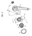
- FIG. 2 is an exploded view of the showerhead 100 according to the first embodiment of the present invention.
- the showerhead 100 may include a body 110, a bubble-generating part 130 generating micro air bubbles, a fluid regulator part 120 adjusting a flow rate of shower water introduced into the bubble-generating part 130, and shower part 150 discharging shower water.
- the body 110 has one end to which a water supply hose (not shown) for supplying shower water is coupled to define an inflow part 111 through which shower water is introduced and the other end communicating with the inflow part 111 to define a discharge part 112 through which the shower water is discharged.
- the inflow part 111 may be screw-coupled to the water supply hose.
- a rubber packing for preventing water from leaking may be disposed on the coupled portion between the inflow part 111 and the water supply hose.
- the body 117 surrounding a passage between the inflow part 111 and the discharge part 112 may serve as a handle to be grasped by a user when the showerhead 100 is used.
- the shower water passing through the discharge part 112 is introduced into the bubble-generating part 130.
- the bubble-generating part 130 includes a plurality of bubble-generating tubes 131a, 131b, 131c, 131d, 132a, 132b, and 132c.
- the washer water may contain micro air bubbles while passing through the bubble-generating tubes 131a, 131b, 131c, 131d, 132a, 132b, and 132c.
- the fluid regulator part 120 is disposed on a back surface of the bubble-generating part 130.
- the fluid regulator part 120 is rotatably disposed.
- the fluid regulator part 120 includes a shield part 121 for opening or closing inlets of the bubble-generating tubes 131 and a manipulation part 122 for manipulating the shield part 121 at the outside of the body 110.
- the manipulation part 122 is coupled to the shield part 121 through the other side of the body 110 so that the shield part 121 is manipulated at the outside of the body 110.
- the bubble-generating part 120 and the fluid regulator part 120 will be described later in more detail.
- the shower water containing the micro air bubbles while passing through the bubble-generating part 130 is introduced into the shower part 150.
- the shower part 150 may have a dome shape. Also, a plurality of shower holes 151 passing through a front surface of the shower part 150 so that the shower water introduced into the shower part 150 is uniformly discharged are uniformly defined in the front surface of the shower part 150.
- the shower part 150 may be coupled to the inside of the discharge part 112 defined in the body 110.
- the shower part 150 may have an outer diameter slightly less than an inner diameter of the discharge part 112 so that the shower part 150 is fitted into the discharge part 112.
- a groove 152 in which a sealing member (not shown) is disposed along an outer circumference of the shower part 150 may be defined in an outer circumference of the shower part 150.
- a rubber ring may be used as the sealing member.
- the sealing member may be disposed on the groove 152 to black leakage of water and also firmly couple the shower part 150 to the body 110.
- a banding part 140 may be disposed along an outer circumference of the shower part 150.
- the banding part 140 has a band shape to expose the shower holes 151 defined in the shower part 150.
- a front surface of the banding part 140 may be flush with that of the shower part 150.
- the banding part 140 may have an inner diameter slightly greater than an outer diameter of the discharge part 112 so that an inner surface of the banding part 140 is fitted into an outer surface of the discharge part 112.
- the banding part 140 may be screw-coupled to the outer surface of the discharge part 112.
- the banding part 140 may cover the coupled portion between the shower part 150 and the discharge part 112 to define an outer appearance of the shower head 100 and also prevent the shower part 150 from being separated from the discharge part 112 by a water pressure.
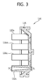
- FIG. 3 is a cross-sectional view of the bubble-generating part.
- each of the plurality of bubble-generating tubes 131a, 131b, 131c, 131d, 132a, 132b, and 132c has an inlet diameter D1, through which shower water is introduced, less than an outlet diameter D2 through which the shower water is discharged.
- each of the plurality of bubble-generating tubes 131a, 131b, 131c, 131d, 132a, 132b, and 132c may be inclinedly expanded in a traveling direction of the shower water (D ⁇ D2).
- the inlet diameter may range of about 1 mm to about 2 mm.
- each of the bubble-generating tubes 131a, 131b, 131c, 131d, 132a, 132b, and 132c has the outlet diameter D2 greater than the inlet diameter D1
- a flow rate may vary within each of the bubble-generating tubes 131a, 131b, 131c, 131d, 132a, 132b, and 132c to generate water-flowing layers.
- a shear force may be applied to the shower water and gases contained in the shower water between the water-flowing layers having the different flow rates and an inner surface of each of the bubble-generating tubes 131a, 131b, 131c, 131d, 132a, 132b, and 132c.
- the gases to which the shear force is applied may be divided into micro air bubbles.
- the shower water may be changed into shower water containing the micro air bubbles while passing through the bubble-generating tubes 131a, 131b, 131c, 131d, 132a, 132b, and 132c.
- the bubble-generating part 130 may include the bubble-generating tubes 131a, 131b, 131c, and 131d which are openable by the shield 121 (that will be described in detail) and the bubble-generating tubes 132a, 132b, and 132c which are always opened.
- the bubble-generating tubes 131a, 131b, 131c, and 131d which are openable by the shield part 121 may be disposed within a radius of rotation of the shield part 121.
- the bubble-generating tubes 132a, 132b, and 132c which are always opened may be disposed out of the radius of rotation of the shield part 121.
- the bubble-generating part 130 may be fitted into an inner surface of the discharge part 112.
- a sealing member such as a rubber ring may be disposed on an outer circumference of the bubble-generating part 130 to enhance the coupling force between the bubble-generating part 130 and the discharge part 112 and prevent washing water from leaking.
- a groove 135 in which the sealing member is disposed may be defined in an outer surface of the bubble-generating part 130.
- An amount of micro air bubbles generated in the bubble-generating part 130 may gradually increase as a flow rate of shower water passing through each of the bubble-generating tubes 131a, 131b, 131c, 131d, 132a, 132b, and 132c.
- each of the bubble-generating tubes 131a, 131b, 131c, 131d, 132a, 132b, and 132c should have a small diameter to increase the flow rate of fluid passing through the bubble-generating tubes 131a, 131b, 131c, 131d, 132a, 132b, and 132c.
- an amount of shower water discharged from the showerhead 100 may decrease.
- the fluid regulator part 120 in which portions of the total bubble-generating tubes 131a, 131b, 131c, 131d, 132a, 132b, and 132c, i.e., the bubble-generating tubes 131a, 131b, 131c, and 131d are openable may be provided so that the sum of sectional areas of the whole passages decreases to increase a generation amount of micro air bubbles, and the sum of the sectional areas of the whole passages increases to further secure the flow rate of shower water.
- FIG. 4 is a view illustrating a position of the shield part when a discharge flow rate is maximized
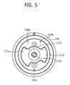
- FIG. 5 is a view illustrating a position of the shield part when a discharge flow rate is minimized.
- the shield part 121 is disposed on a back surface of the bubble-generating part 130.
- the shield part 121 may include a frame 121d connected to a rotation shaft and shield plates 121a and 121b extending outward from the frame 121d.
- a support 122c coupled to the manipulation part 122 may be disposed on a central portion of the frame 121d. An end of the support 122c coupled to the manipulation part 122 may pass through the body 110. Also, the manipulation part 122 may be coupled to the end of the support 122c passing through the body 110.
- a user may rotate the manipulation part 122 disposed outside the body 110 to rotate the shield part 121.
- the shield plates 121a and 121b may rotate to shield inlets 134a, 134b, 134c, 134d of the bubble-generating tube 132.
- FIG. 4 illustrates a state in which the inlets 134a, 134b, 134c, 134d of the bubble-generating tube 132 are not blocked by the shield plates 121a and 121b.
- the bubble-generating tubes 133a, 133b, 133c which are always opened as shown in FIG. 4 may be disposed out of the radius of rotation of the shield plates 121a and 121b. Thus, the bubble-generating tubes 133a, 133b, 133c may not be blocked by the shield plates 121a and 121b.
- the inlets 134a, 134b, 134c, 134d of the openable bubble-generating tubes 131a, 131b, 131c, and 131d are closed one by one.
- all of the inlets 134a, 134b, 134c, and 134d of the openable bubble-generating tubes 131a, 131b, 131c, and 131d may be closed.
- the shield plates 121a and 121b may have a plurality of openings corresponding to the inlets 134a, 134b, 134c, and 134d of the openable bubble-generating tubes 131a, 131b, 131c, and 131d.
- the openings correspond to the inlets 134a, 134b, 134c, and 134d of the openable bubble-generating tubes 131a, 131b, 131c, and 131d
- all of the bubble-generating tubes 131a, 131b, 131c, 131d, 132a, 132b, and 132c may be opened.
- the inlets 134a, 134b, 134c, and 134d of the openable bubble-generating tubes 131a, 131b, 131c, and 131d may be closed, and only the inlets 133a, 133b, 133c of the always opened bubble-generating tubes 132a, 132b, and 132c may be opened.
- Protrusions (not shown) disposed at a predetermined distance in a ring shape with respect to the rotation shaft may be disposed between the manipulation part 122 and the body 110 or between the bubble-generating part 130 and the shield plates 121a and 121b. This is done for a reason in which, when the manipulation part 122 rotates, the user recognizes click feeling due to the rotation of the manipulation part 122 through a sense of touch to estimate a rotation amount of the shield plates 121a and 121b, and also, the shield plates 121a and 121b induce the bubble-generating tubes 131a, 131b, 131c, and 131d so that the openable bubble-generating tubes 131a, 131b, 131c, and 131d are precisely disposed at openable positions thereof.
- the showerhead 100 may discharge shower water that contains micro air bubbles by passing through the bubble-generating part 130. Also, the showerhead 100 may include the fluid regulator part 120 to regulate an amount of the micro air bubble contained in the shower water and a discharge flow rate of the shower water.
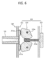
- FIG. 6 is a cross-sectional view of a fluid regulator part according to the second embodiment of the present invention.
- a fluid regulator part 220 is disposed on a back surface of a bubble-generating part 130. Also, the fluid regulator part 220 includes a shield part for opening or closing an inlet of a bubble-generating tube 131, a manipulation part 222 for manipulating the shield part 221 at the outside of a body 110, and an interlocking part disposed between the shield part 221 and the manipulation part 222.
- the shield part 221 may include a pair of sliding plates 221a and 221b to open or close the inlet of the bubble-generating tube 131 in a slide manner.
- One surface of each of the sliding plates 221a and 221b may be closely attached to the back surface of the bubble-generating part 130.
- a first tooth may be disposed on a back surface of each of the sliding plates 221a and 221b.
- the interlocking part 223 between the shield part 221 and the manipulation part 222 may convert a rotation movement of the manipulation part 222 disposed outside the body 110 into a vertical movement of each of the sliding plates 221a and 221b.
- the rotation movement of the manipulation part 222 is converted into the vertical movement of each of the sliding plates 221a and 221b through various methods, the current embodiment utilizes a rack and pinion as an example.
- a cylindrical screw part 222a on which a first male thread is disposed on a side surface thereof may be disposed on an end of the manipulation part 222.
- the interlocking part 223 may include a fan-shaped plate.
- a second tooth corresponding to the first tooth disposed on any one of the sliding plates 221a and 221b is disposed on one portion of a curved surface of the interlocking part 223.
- a third tooth corresponding to the first male thread disposed on the screw part 222a is disposed on the other portion of the curved surface of the interlocking part 223.
- the interlocking part 223 may be disposed on each of both sides of the screw part 222a to vertically move each of the sliding plates 221a and 221b.
- the screw part 222a disposed on the one end of the manipulation part 222 rotates to rotate the interlocking part 223.
- the interlocking part 223 may rotate in directions opposite to each other.
- the shield plates 221a and 221b may approach each other, and the inlet of the bubble-generating tube 131 may be narrowed to reduce a sectional area of a passage thereof. Thus, occurrence of micro air bubbles may be activated.
- the interlocking part 223 may rotate in an opposite direction so that the sliding plates 221a and 221b are away from each other.
- the passage may be widened in sectional area to secure a more amount of shower water.
- the user may control the manipulation part 222 to regulate a flow rate of shower water and a generation amount of micro air bubbles according to user's tastes.
- a plurality of interlocking parts 223 may be parallely disposed on the fixing shaft 223a to regulate flow rates of a plurality of bubble-generating tubes 131 at the same time. Also, although not shown, the plurality of interlocking parts 223 may be linked with the screw part 222a to operate so that the flow rates of the plurality of bubble-generating tubes 131 at the same time.
- FIG. 7 is a cross-sectional view of a fluid regulator part according to the third embodiment of the present invention.
- a fluid regulator part 320 includes a shield part 321 disposed on a side of an inlet of a bubble-generating tube 131 to move in a length direction of the bubble-generating tube 131, thereby opening or closing the inlet of the bubble-generating tube 131 and a manipulation part 322 for adjusting a distance between the shield part 321 and the inlet of the bubble-generating tube 131 at the outside of a body 110.
- the shield part 321 may include a shield plate 321a and a fluid regulator pin 321b disposed on one surface of the shield plate 321a.
- a guide bar 311 may be disposed on a back surface of the bubble-generating part 130 to guide the shield part 321 in the length direction of the bubble-generating tube 131 so that the fluid regulator pin 321b is inserted into the bubble-generating tube 131.
- a hole passing through the shield plate 321a may be defined in an edge of the shield plate 321 to correspond to the installed position of the guide bar 311.
- the fluid regulator pin 321b may have a cone shape that has a diameter gradually decreasing toward the bubble-generating tube 131 at a position corresponding to the inlet of the bubble-generating tube 131.
- the cone shape may have a bottom diameter equal to or greater than an inlet diameter of the bubble-generating tube 131.
- the current embodiment adjusts the distance between the shield part 321 and the inlet of the bubble-generating tube 131 by using a bolt part 323a and a nut part 323b as an example.
- the bolt part 323a includes a cylindrical body.
- a second male thread may be disposed on a portion or the while of a side surface of the cylindrical body.
- the nut part 323b has a cylindrical groove to insert the bolt part 323a therein.
- a second female thread corresponding to the second male thread disposed on the bolt part 323a is disposed along the groove.
- the bolt part 323a may be disposed on a back surface of the shield plate 321a, and the nut part 323b may be coupled to the bolt part 323a in a state where the nut part 323b is disposed on an end of the manipulation part 323.
- the nut part 323 b may be disposed on the back surface of the shield plate 321a, and the bolt part 323a may be disposed on the end of the manipulation part 322.
- the nut part 323b disposed on the end of the manipulation part 322 rotates together with the manipulation part 322.
- the nut part 323b may rotate to push the bolt part 323a.
- the shield plate 321a coupled to an end of the bolt part 323a may be pushed together with the bolt part 323a along the guide bar 311.
- the fluid regulator pin 321b may be inserted into the bubble-generating tube 131 through the inlet of the bubble-generating tube 131 to reduce a sectional area of the passage, thereby activating the occurrence of the micro air bubbles.
- the bolt part 323a may be inserted into the nut part 323b.
- the fluid regulator pin 321b may be separated from the bubble-generating tube 131 to the outside through the inlet of the bubble-generating tube 131 to widen the sectional area of the passage, thereby securing a more amount of shower water.
- the user may control the manipulation part 322 to control a flow rate of shower water and a generation amount of micro air bubbles according to user's tastes.
- the fluid regulator pin 321b may be provided in plurality to regulate flow rates of the whole or portions of the plurality of bubble-generating tube 131.
- FIG. 8 is an exploded view of a showerhead according to a fourth embodiment of the present invention.
- the showerhead 400 may include a body 110, an acceleration part 410 for increasing a flow rate of shower water, a bubble-generating part 130 for generating micro air bubbles, a bypass part 420 for bypassing the shower water containing the micro air bubbles, and a shower part 150 for discharging the washer water containing the micro air bubbles.
- the showerhead 400 according to the fourth embodiment further includes the acceleration part 410 for increasing the flow rate of the shower water and the bypass part 420 for bypassing the shower water containing the micro air bubbles.
- the acceleration part 410 may have a plate shape in which an ejecting hole 411 is defined.
- the acceleration part 410 may be disposed inside a discharge part 112.
- the ejecting hole 411 may increase a flow rate of shower water introduced into the bubble-generating part 130.
- the reason in which the flow rate of the shower water increases by the acceleration part 410 is because micro air bubbles are well generated in the bubble-generating part 130 as the flow rate of the shower water increased.
- the ejecting hole 411 may have a diameter of about 3 mm to about 7 mm.
- the ejecting hole 411 may have a tapered shape of which a diameter increases in an ejection direction of the shower water.
- the ejecting hole 411 has the tapered shape, if a plurality of bubble-generating tubes 131a, 131b, and 131c are radially disposed in the bubble-generating part 130, the shower water passing through the ejecting hole 411 may be more uniformly introduced into the bubble-generating tubes 131a, 131b, and 131c.
- the shower water When the shower water is initially introduced into the bubble-generating tubes 131a, 131b, and 131c in a state where the insides of the bubble-generating tubes 131a, 131b, and 131c are in dry condition, the shower water may have a particular resistance. Thus, a share force may not largely act to discharge the shower water in which the micro air bubbles are not generated.
- the bypass part 420 may be provided so that the shower water passing through the bubble generating part 130 is directly introduced into the shower hole 151, but is bypassed by the bypass part 420 to allow a portion of the shower water to be re-introduced into the bubble-generating tubes 131a, 131b, and 131c.
- the bypass part 420 may include a collision wall 421 that is spaced apart from front ends of the bubble-generating tubes 131a, 131b, and 131c to surround the bubble-generating tubes 131a, 131b, and 131c and through holes 422 radially defined in inner and outer circumferences of the collision wall 421.
- portions of the bubble-generating tubes 131a, 131b, and 131c may be closed while the shower water collides with the collision wall 421 disposed on the front surfaces of the bubble-generating tubes 131a, 131b, and 131c and thus is bypassed toward the through holes 422.
- the following shower water may be affected by a share force to generate the micro air bubbles.
- the fluid regulator part 120 may be disposed on a front surface of the bubble-generating part 130 or between the bubble-generating part 130 and the acceleration part 410.
- FIG. 9 is a cross-sectional view of a showerhead body according to a fifth embodiment of the present invention.
- the showerhead 500 according to the fifth embodiment includes a body 510 for swirling shower water introduced into the showerhead 500.
- a path through which an inflow part 111 communicates with the discharge part 112 may be dislocated with a central axis of a length direction of a body 110.
- an outlet 113 of the path may be spaced apart from the central axis.
- the shower water When shower water is introduced through a passage having the above-described structure, the shower water may rotate along an inner surface of the discharge part 112 to generate the eddy.
- a guide for guiding the shower water in a left or right direction may be disposed on the outlet of the path to generate the eddy.
- a shear force may act on the shower water to primarily generate micro air bubbles. Then, gases contained in the shower water may be finely divided to effectively generate micro air bubbles in the bubble-generating part 130.
- FIG. 10A is a cross-sectional view of a showerhead body according to a sixth embodiment of the present invention.
- the showerhead 600 may include an auxiliary passage 610, which is branched from a passage connecting an inflow part 111 to a discharge part 112 so that an outlet is disposed between a bubble-generating part 130 and a shower part 150, within a body 110.
- the showerhead 600 may discharge a more amount of shower water.
- a switch 620 for opening or closing the auxiliary passage 610 may be disposed on a side of the body 110.
- FIG. 10B is a cross-sectional view taken along line B-B' of FIG. 10A .
- the switch 610 is disposed on the side of the body 110 to pass through the auxiliary passage 610.
- a water flow hole 621 communicating with the auxiliary passage 610 is defined in the switch 620.
- a front surface of the switch 620 is exposed to the outside. Thus, a user may move the front surface of the switch 620 exposed to the outside of the body 110 in a left a right direction to open or close the auxiliary passage 610.
- a space 630 in which the switch 620 moves in the left or right direction is defined in the body 110.
- the water flow hole 621 and the auxiliary passage 610 may overlap with each other.
- the shower water may move through the auxiliary passage 610.
- the switch 620 blocks the auxiliary passage 610.
- the switch 620 may have various shapes to block the auxiliary passage.
- the switch 420 may be replaced with a valve that is capable of adjusting a flow rate (an amount of shower water).
Landscapes
- Nozzles (AREA)
- Bathtubs, Showers, And Their Attachments (AREA)
- Domestic Plumbing Installations (AREA)
Applications Claiming Priority (2)
| Application Number | Priority Date | Filing Date | Title |
|---|---|---|---|
| KR1020100085615A KR101053229B1 (ko) | 2010-09-01 | 2010-09-01 | 미세기포 발생 샤워헤드 |
| PCT/KR2011/004942 WO2012030062A2 (ko) | 2010-09-01 | 2011-07-06 | 미세기포 발생 샤워헤드 |
Publications (2)
| Publication Number | Publication Date |
|---|---|
| EP2612581A2 true EP2612581A2 (de) | 2013-07-10 |
| EP2612581A4 EP2612581A4 (de) | 2014-04-30 |
Family
ID=44932707
Family Applications (1)
| Application Number | Title | Priority Date | Filing Date |
|---|---|---|---|
| EP11822037.5A Withdrawn EP2612581A4 (de) | 2010-09-01 | 2011-07-06 | Duschkopf zur erzeugung von mikroluftblasen |
Country Status (7)
| Country | Link |
|---|---|
| US (1) | US9289784B2 (de) |
| EP (1) | EP2612581A4 (de) |
| JP (1) | JP5691027B2 (de) |
| KR (1) | KR101053229B1 (de) |
| CN (1) | CN103079441B (de) |
| SG (1) | SG188357A1 (de) |
| WO (1) | WO2012030062A2 (de) |
Cited By (1)
| Publication number | Priority date | Publication date | Assignee | Title |
|---|---|---|---|---|
| EP4520881A1 (de) * | 2023-09-08 | 2025-03-12 | Hansgrohe SE | Brause mit mengenzuschalteinrichtung |
Families Citing this family (17)
| Publication number | Priority date | Publication date | Assignee | Title |
|---|---|---|---|---|
| JP5823851B2 (ja) * | 2011-12-21 | 2015-11-25 | 株式会社三栄水栓製作所 | 吐水具 |
| JP5285794B1 (ja) * | 2012-06-08 | 2013-09-11 | 株式会社 Mtg | シャワーヘッド |
| CN102921370B (zh) * | 2012-11-08 | 2014-09-10 | 广西华纳新材料科技有限公司 | 文丘里管反应器 |
| KR101655182B1 (ko) * | 2013-12-11 | 2016-09-07 | 이장우 | 살수판 보강부가 구비되는 유체 분사장치 |
| CN108534360A (zh) * | 2017-03-02 | 2018-09-14 | 青岛经济技术开发区海尔热水器有限公司 | 具有微气泡水洗功能的热水器 |
| US10898909B2 (en) * | 2017-10-25 | 2021-01-26 | Pioneer Industries, Inc. | Water pressure boosting device |
| CN110314780B (zh) * | 2018-03-30 | 2024-09-27 | 艾欧史密斯(中国)热水器有限公司 | 花洒及淋浴设备 |
| CN110314781B (zh) * | 2018-03-30 | 2024-09-03 | 艾欧史密斯(中国)热水器有限公司 | 花洒及淋浴设备 |
| CN113543889A (zh) | 2019-03-22 | 2021-10-22 | 韦克斯曼消费产品集团有限公司 | 具有在循环中依次启动的多对喷嘴的花洒 |
| CN110833936B (zh) * | 2019-06-06 | 2024-04-12 | 鹤山市玛旭卫浴科技有限公司 | 一种微细气泡莲蓬头 |
| CN112680928B (zh) * | 2019-10-17 | 2025-02-25 | 青岛海尔洗衣机有限公司 | 微气泡喷头及具有该微气泡喷头的洗涤设备 |
| CN114054224B (zh) * | 2020-07-30 | 2023-06-30 | 无锡小天鹅电器有限公司 | 喷淋装置和洗涤系统 |
| CN114054228B (zh) * | 2020-07-30 | 2023-03-21 | 无锡小天鹅电器有限公司 | 喷淋装置和洗涤系统 |
| CN114054227B (zh) * | 2020-07-30 | 2023-03-21 | 无锡小天鹅电器有限公司 | 喷淋装置和洗涤系统 |
| CN114192292B (zh) * | 2020-08-26 | 2023-09-22 | 无锡小天鹅电器有限公司 | 喷淋装置和洗涤系统 |
| CN112741522A (zh) * | 2020-12-28 | 2021-05-04 | 深圳市米谷智能有限公司 | 一种小气泡洁面仪及清洁结构 |
| CN114042550B (zh) * | 2021-10-19 | 2022-07-05 | 厦门欧圣斯卫浴有限公司 | 一种出水装置的水花形态调节结构 |
Family Cites Families (20)
| Publication number | Priority date | Publication date | Assignee | Title |
|---|---|---|---|---|
| US5433384A (en) * | 1994-06-24 | 1995-07-18 | Jing Mei Industrial Limited | Push button controlled multifunction shower head |
| JP2000107063A (ja) * | 1998-10-08 | 2000-04-18 | Hiroyuki Ebara | シャワー装置 |
| US6607148B1 (en) * | 2000-01-13 | 2003-08-19 | Kohler Co. | Shower head |
| WO2001068995A1 (fr) * | 2000-03-17 | 2001-09-20 | Toto Ltd. | Buse pour delivrer de l'eau mousseuse |
| US6412711B1 (en) * | 2001-02-12 | 2002-07-02 | Chen-Yueh Fan | Adjustable shower head |
| JP2004136085A (ja) | 2002-09-27 | 2004-05-13 | Toto Ltd | マッサージノズル及びマッサージシステム |
| DE102004059329A1 (de) * | 2004-12-01 | 2006-06-08 | Hansgrohe Ag | Brausekopf für eine Sanitärbrause |
| US7818828B2 (en) * | 2005-09-13 | 2010-10-26 | Hua-Song Zhou | Multi-functional shower head |
| JP4736672B2 (ja) | 2005-09-27 | 2011-07-27 | パナソニック電工株式会社 | シャワー装置 |
| JP4710517B2 (ja) * | 2005-09-27 | 2011-06-29 | パナソニック電工株式会社 | シャワー装置 |
| JP2007209509A (ja) * | 2006-02-09 | 2007-08-23 | Matsushita Electric Ind Co Ltd | 微細気泡発生装置およびそれを用いたシャワー装置 |
| US8066203B2 (en) * | 2006-07-05 | 2011-11-29 | Zhou Huasong | Multifunction shower head |
| US7380731B1 (en) * | 2006-09-13 | 2008-06-03 | Da Yuan Sheng Industrial Co., Ltd. | Water sprayer having two water different spraying modes |
| US8794543B2 (en) * | 2006-12-28 | 2014-08-05 | Water Pik, Inc. | Low-speed pulsating showerhead |
| JP4925310B2 (ja) | 2007-03-27 | 2012-04-25 | パナソニック株式会社 | シャワー装置 |
| US8020786B2 (en) * | 2008-06-02 | 2011-09-20 | Lomak Industrial Co., Ltd. | Shower head |
| JP2012040448A (ja) * | 2008-11-14 | 2012-03-01 | Yasutaka Sakamoto | マイクロバブル発生装置 |
| KR100902136B1 (ko) * | 2008-11-14 | 2009-06-10 | (주)림코 | 마이크로 기포 발생장치 및 이를 이용한 욕조 시스템 |
| KR100942589B1 (ko) * | 2009-06-02 | 2010-02-16 | (주)엠이씨 | 마이크로 버블 발생 샤워기 |
| US9328491B2 (en) * | 2010-03-31 | 2016-05-03 | Toto Ltd. | Water spouting device |
-
2010
- 2010-09-01 KR KR1020100085615A patent/KR101053229B1/ko active Active
-
2011
- 2011-07-06 EP EP11822037.5A patent/EP2612581A4/de not_active Withdrawn
- 2011-07-06 US US13/820,337 patent/US9289784B2/en active Active
- 2011-07-06 JP JP2013524027A patent/JP5691027B2/ja not_active Expired - Fee Related
- 2011-07-06 WO PCT/KR2011/004942 patent/WO2012030062A2/ko not_active Ceased
- 2011-07-06 CN CN201180042284.5A patent/CN103079441B/zh active Active
- 2011-07-06 SG SG2013015524A patent/SG188357A1/en unknown
Cited By (2)
| Publication number | Priority date | Publication date | Assignee | Title |
|---|---|---|---|---|
| EP4520881A1 (de) * | 2023-09-08 | 2025-03-12 | Hansgrohe SE | Brause mit mengenzuschalteinrichtung |
| DE102023124265A1 (de) * | 2023-09-08 | 2025-03-13 | Hansgrohe Se | Brause mit Mengenzuschalteinrichtung |
Also Published As
| Publication number | Publication date |
|---|---|
| US20130161418A1 (en) | 2013-06-27 |
| JP2013535298A (ja) | 2013-09-12 |
| CN103079441A (zh) | 2013-05-01 |
| JP5691027B2 (ja) | 2015-04-01 |
| EP2612581A4 (de) | 2014-04-30 |
| SG188357A1 (en) | 2013-04-30 |
| US9289784B2 (en) | 2016-03-22 |
| CN103079441B (zh) | 2016-05-25 |
| KR101053229B1 (ko) | 2011-08-01 |
| WO2012030062A3 (ko) | 2012-04-26 |
| WO2012030062A2 (ko) | 2012-03-08 |
Similar Documents
| Publication | Publication Date | Title |
|---|---|---|
| EP2612581A2 (de) | Duschkopf zur erzeugung von mikroluftblasen | |
| EP3309306B1 (de) | Kombinierte dusche | |
| KR101178550B1 (ko) | 미세기포 발생 샤워헤드 | |
| KR102376857B1 (ko) | 미세버블 발생장치 및 이를 이용한 기능성 샤워기헤드 | |
| KR102371303B1 (ko) | 분수형 토수구를 갖춘 수전금구 | |
| JP5302930B2 (ja) | 浄水器専用水栓 | |
| CN210600290U (zh) | 一种无压水龙头及自动皂液器装置 | |
| KR100596485B1 (ko) | 연수기의 이온교환수지 재생장치 | |
| CN110594450A (zh) | 一种无压水龙头及自动皂液器装置 | |
| JP2014084651A (ja) | 水栓装置 | |
| KR20230146807A (ko) | 수전장치 | |
| KR20120070936A (ko) | 푸쉬 파우셋 및 이를 포함하는 언더싱크형 정수기 | |
| KR102135849B1 (ko) | 싱크대 수전용 언더싱크 정수시스템 | |
| KR20220114204A (ko) | 수전용 필터조립체 일체형 선반샤워기 수전 | |
| CN217056440U (zh) | 龙头软水机和用于龙头软水机的控制阀 | |
| KR101774908B1 (ko) | 수도 직결 자가 교체형 정수 샤워기 | |
| KR101339338B1 (ko) | 수전금구용 카트리지 | |
| JP3102985U (ja) | 浄水器 | |
| KR200204198Y1 (ko) | 자화맛사지샤워기 | |
| KR102376856B1 (ko) | 샤워기 | |
| CN223753412U (zh) | 一种出水组件及出水装置 | |
| JP2007032798A (ja) | プッシュ式水栓 | |
| JP2006307519A (ja) | 切替部材 | |
| RU2476273C2 (ru) | Универсальная водосберегающая насадка для водораздаточных средств | |
| KR200362554Y1 (ko) | 연수장치 및 그 연수장치가 구비된 바디 안마 샤워기 |
Legal Events
| Date | Code | Title | Description |
|---|---|---|---|
| PUAI | Public reference made under article 153(3) epc to a published international application that has entered the european phase |
Free format text: ORIGINAL CODE: 0009012 |
|
| 17P | Request for examination filed |
Effective date: 20130301 |
|
| AK | Designated contracting states |
Kind code of ref document: A2 Designated state(s): AL AT BE BG CH CY CZ DE DK EE ES FI FR GB GR HR HU IE IS IT LI LT LU LV MC MK MT NL NO PL PT RO RS SE SI SK SM TR |
|
| DAX | Request for extension of the european patent (deleted) | ||
| A4 | Supplementary search report drawn up and despatched |
Effective date: 20140331 |
|
| RIC1 | Information provided on ipc code assigned before grant |
Ipc: B01F 3/04 20060101ALI20140325BHEP Ipc: A47K 3/28 20060101AFI20140325BHEP Ipc: B05B 1/18 20060101ALI20140325BHEP Ipc: B01F 5/00 20060101ALI20140325BHEP Ipc: B05B 1/16 20060101ALI20140325BHEP |
|
| GRAP | Despatch of communication of intention to grant a patent |
Free format text: ORIGINAL CODE: EPIDOSNIGR1 |
|
| INTG | Intention to grant announced |
Effective date: 20180606 |
|
| STAA | Information on the status of an ep patent application or granted ep patent |
Free format text: STATUS: THE APPLICATION IS DEEMED TO BE WITHDRAWN |
|
| 18D | Application deemed to be withdrawn |
Effective date: 20181017 |