EP2610663B1 - Steuerschaltungsvorrichtung und Endoskopvorrichtung - Google Patents
Steuerschaltungsvorrichtung und Endoskopvorrichtung Download PDFInfo
- Publication number
- EP2610663B1 EP2610663B1 EP12199007.1A EP12199007A EP2610663B1 EP 2610663 B1 EP2610663 B1 EP 2610663B1 EP 12199007 A EP12199007 A EP 12199007A EP 2610663 B1 EP2610663 B1 EP 2610663B1
- Authority
- EP
- European Patent Office
- Prior art keywords
- substrate
- barrier
- circuit
- control unit
- barrier circuit
- Prior art date
- Legal status (The legal status is an assumption and is not a legal conclusion. Google has not performed a legal analysis and makes no representation as to the accuracy of the status listed.)
- Not-in-force
Links
Images




Classifications
-
- H—ELECTRICITY
- H04—ELECTRIC COMMUNICATION TECHNIQUE
- H04N—PICTORIAL COMMUNICATION, e.g. TELEVISION
- H04N7/00—Television systems
- H04N7/18—Closed-circuit television [CCTV] systems, i.e. systems in which the video signal is not broadcast
-
- G—PHYSICS
- G02—OPTICS
- G02B—OPTICAL ELEMENTS, SYSTEMS OR APPARATUS
- G02B23/00—Telescopes, e.g. binoculars; Periscopes; Instruments for viewing the inside of hollow bodies; Viewfinders; Optical aiming or sighting devices
- G02B23/24—Instruments or systems for viewing the inside of hollow bodies, e.g. fibrescopes
- G02B23/2476—Non-optical details, e.g. housings, mountings, supports
- G02B23/2492—Arrangements for use in a hostile environment, e.g. a very hot, cold or radioactive environment
-
- H—ELECTRICITY
- H05—ELECTRIC TECHNIQUES NOT OTHERWISE PROVIDED FOR
- H05K—PRINTED CIRCUITS; CASINGS OR CONSTRUCTIONAL DETAILS OF ELECTRIC APPARATUS; MANUFACTURE OF ASSEMBLAGES OF ELECTRICAL COMPONENTS
- H05K1/00—Printed circuits
- H05K1/02—Details
- H05K1/0201—Thermal arrangements, e.g. for cooling, heating or preventing overheating
- H05K1/0203—Cooling of mounted components
Definitions
- the present invention relates to a control circuit apparatus and an endoscope apparatus.
- an endoscope apparatus configured to observe a place such as the inside of an observation object, the inside of which an observer cannot easily directly observe, is well known.
- the endoscope apparatus includes a long insertion section, and an image acquisition unit installed at a distal end of the insertion section.
- the endoscope apparatus is generally classified as a medical endoscope configured to observe the inside of a human body, or an industrial endoscope configured to observe the inside of a machine.
- the industrial endoscope may be used in environments in which an explosive atmosphere is likely to be filled, such as a boiler, a chemical plant, or an engine of an automobile or an aircraft.
- an endoscope apparatus that is assumed to be used in environments surrounded by a combustible gas or dust is disclosed in Japanese Unexamined Patent Application, First Publication No. 2007-152020 .
- the endoscope apparatus can be used in a place in which an explosion hazard is present.
- Japanese Unexamined Patent Application, First Publication No. 2010-154708 discloses that, as a resin is filled into a substrate in which electronic parts having a large calorific value are mounted, a combustible is prevented from coming in contact with the electronic parts.
- Document WO 2010/103426 discloses a device designed for the video inspection of enclosed environments which typically contain explosive fumes and which typically comprise containers for holding hydrocarbons, but also closed environments of various types such as tunnels or similar where the formation of potentially explosive gases is foreseeable.
- the device comprises a metallic casing made from a sealed material suitable for preventing any form of emission towards Zone 0 class environments, charged with explosive fumes or of sparks or electrical charges of any type produced by the components inside the casing, and where the container is designed to hold digital video cameras and suitable lights, and where the video cameras, the lights and the associated electronic circuits are embedded in a resin filling; or similar which encapsulates the system components inside the metallic casing, thereby making it completely impossible for sparks or electrical charges of any type to be emitted from the casing.
- a control circuit board includes the features of claim 1.
- the second barrier circuit has at least a first part having a relatively small surface area and a relatively large assumed maximum calorific value upon malfunction condition, and a second part having a relatively large surface area and a relatively small assumed maximum calorific value upon malfunction condition.
- the first part of the second barrier circuit may be disposed at a position spaced further apart from the first compartment than the second part of the second barrier circuit such that distances from an outer edge of the first compartment to a point nearest the first compartment of an outer edge of a region in which the temperature of the substrate exceeds the upper limit temperature among the rated temperatures of the substrate due to heat generation of the first part of the second barrier circuit and a point nearest the first compartment of an outer edge of a region in which the temperature of the substrate exceeds the upper limit temperature among the rated temperatures of the substrate due to heat generation of the second part of the second barrier circuit are substantially equal to each other.
- the first part of the second barrier circuit may be a part having the same specification as of the first part of the first barrier circuit, rather than the first part itself of the first barrier circuit.
- the second part of the second barrier circuit may be a part having the same specification as of the second part of the first barrier circuit, rather than the second part itself of the first barrier circuit.
- control circuit board according to the first aspect may have a filling frame formed at one of both surfaces in a thickness direction of the substrate, on which the first barrier circuit is mounted, and into which the heat-resistant resin is filled, and the filling frame may be formed to surround at least the first part in the first barrier circuit.
- the control circuit board according to the second aspect has a first filling frame formed at one of both surfaces in the thickness direction of the substrate, in which the first barrier circuit is mounted, and into which the heat-resistant resin is filled, and a second filling frame formed at one of both surfaces in the thickness direction of the substrate, in which the second barrier circuit is mounted, and into which the heat-resistant resin is filled.
- the first filling frame may be formed to surround at least the first part of the first barrier circuit
- the second filling frame may be formed to surround at least the first part of the second barrier circuit.
- An endoscope apparatus includes a control circuit apparatus according to any one of first to fourth aspects of the present invention, a main body having the control circuit apparatus therein, a long insertion section having one end attached to the main body, an imaging unit installed at the other end of the insertion section and configured to image an object, an lighting unit installed at the other end of the insertion section and configured to radiate light to the object, and a control unit installed at the main body and configured to control the imaging unit and the lighting unit.
- the control unit has an imaging control unit configured to receive power from one barrier circuit of the plurality of barrier circuits and operate the imaging unit, and an lighting control unit configured to receive power from another barrier circuit of the plurality of barrier circuits and operate the lighting unit.
- the one barrier circuit may be one of the first barrier circuit and the second barrier circuit, and the other barrier circuit may be the other of, the first barrier circuit and the second barrier circuit.
- the heat-resistant resin may be disposed at two or more different places on the substrate.
- FIG. 1 is a perspective view showing an endoscope apparatus of the embodiment.
- FIG. 2 is a front view showing an insertion section of the endoscope apparatus of the embodiment.
- FIG. 3 is a cross-sectional view taken along line A-A of FIG. 2 .
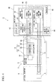
- FIG. 4 is a block diagram of the endoscope apparatus of the embodiment.
- An endoscope apparatus 1 shown in FIG. 1 is an apparatus configured to observe a place such as the inside of an observation object, the inside of which an observer cannot easily directly observe.
- the endoscope apparatus 1 includes a long insertion section 2 inserted into the observation object from a distal end 2a thereof, and a main body 40 fixed to a proximal end 2b of the insertion section 2.
- the insertion section 2 includes a cylindrical flexible section 3 having flexibility, and an optical adaptor 6 detachably attached to the flexible section 3 at the distal end 2a.
- An lighting unit 7 configured to radiate illumination light to the observation object and an image acquisition unit 15 configured to acquire an image of the observation object irradiated with the illumination light are installed in the insertion unit 2.
- the lighting unit 7 and the image acquisition unit 15 are disposed inside the optical adaptor 6, the flexible section 3, and the main body 40.
- a bending unit 4 configured to bend the flexible section 3 and a distal end hard member 5 configured to support the lighting unit 7 and the image acquisition unit 15 at a distal end side of the bending unit 4 are installed at a distal end of the flexible section 3.
- the distal end hard member 5 is formed of, for example, metal or resin, and has a substantially circular column shape having a center axis in a central axial direction of the insertion section 2.
- the distal end hard member 5 has a through-hole into which the lighting unit 7 is inserted, and a through-hole into which the image acquisition unit 15 is inserted.
- the optical adaptor 6 is an adaptor configured to protect a distal end surface of the flexible section 3, or change light distribution of the lighting unit 7 or a viewing angle of the image acquisition unit 15.
- a direct viewing type adaptor in which an imaging field of vision is directed in the central axial direction of the insertion section 2 is employed as an example of the optical adaptor 6.
- a so-called lateral viewing type adaptor in which an imaging field of vision is directed in a direction crossing a central axis of the insertion section 2, may be employed as the optical adaptor 6.
- the lighting unit 7 includes a light emission unit 8 installed in the optical adaptor 6, an interconnection 11 disposed in the flexible section 3 to supply driving power to the light emission unit 8, and an lighting control unit 13 installed in the main body 40.
- the light emission unit 8 has a light source 9 constituted by, for example, a light emitting diode (LED) or a laser diode (LD), and a contactor 10 electrically connected to the light source 9.
- a light source 9 constituted by, for example, a light emitting diode (LED) or a laser diode (LD)
- a contactor 10 electrically connected to the light source 9.
- the interconnection 11 has a distal end disposed at the distal end of the flexible section 3, and a proximal end disposed in the main body 40.
- a connecting terminal 11a installed to be exposed to the distal end surface of the flexible section 3 is fixed to the distal end of the interconnection 11.
- a contact member having spring characteristics protruding in a central axial direction of the insertion section 2 is installed at the contactor 10.
- the image acquisition unit 15 includes an optical adaptor object optical system 16 installed to be exposed to the distal end surface of the optical adaptor 6, an imaging unit 17 disposed in the distal end of the insertion section 2, an interconnection 26 having a distal end connected to the imaging unit 17 and a proximal end disposed in the main body 40, and an imaging control unit 30 connected to the proximal end of the interconnection 26 and installed in the main body 40.
- the optical adaptor object optical system 16 is a plate-shaped member having optical transparency, and is installed to change a direction of a field of vision or a viewing angle of an observation image, and observation depth.
- the imaging unit 17 has an object optical system 18 and an imaging circuit unit 19.
- the object optical system 18 is an optical system configured to guide external light passing through the optical adaptor object optical system 16 to the imaging circuit unit 19, and is installed to acquire an image of the observation object in the imaging circuit unit 19.
- the imaging circuit unit 19 has a support 20, a circuit substrate 21, an imaging device 22, and an image transmission unit 23.
- the support 20 is formed of, for example, resin or metal in a predetermined shape, and supports the circuit substrate 21 and respective electronic parts mounted in the circuit substrate 21.
- the circuit substrate 21 is a substrate on which a predetermined interconnection pattern is formed, and in the embodiment, is a flexible printed board.
- the circuit substrate 21 is fixed to an outer surface of the support 20.
- the imaging element 22 is an electronic part mounted on the circuit substrate 21, and is disposed on an optical axis of the object optical system 18.
- a CCD image sensor charge coupled device image sensor
- CMOS image sensor complementary metal oxide semiconductor image sensor
- the image transmission unit 23 is mounted on the circuit substrate 21.
- the image transmission unit 23 includes an oscillator 24 configured to generate a clock signal having a predetermined frequency, and a serializer circuit 25 configured to convert image data acquired by the imaging device 22 into serial data based on the clock signal issued from the oscillator 24.
- the image data converted into the serial data by the serializer circuit 25 passes through the interconnection 26 to be transmitted to the imaging control unit 30 (to be described later).
- the interconnection 26 has a power line 27 configured to supply driving power from the imaging control unit 30 to the imaging circuit unit 19, and a signal line 28 configured to output a signal from the imaging circuit unit 19 to the imaging control unit 30.
- Driving power is supplied to the power line 27, different from the lighting control unit 13.
- the number and disposition of the signal line 28 are set based on a transmission type of the image transmission unit 23.
- the main body 40 includes a grip unit 41 gripped by an observer who uses the endoscope apparatus 1, a display unit 42 configured to display an image acquired by the image acquisition unit 15, and a manipulation input unit 43 configured to allow the observer to manipulate an operation of the lighting unit 7 or the image acquisition unit 15.
- a control circuit apparatus 46 including the lighting control unit 13, the imaging control unit 30, and a main control unit 44 is installed in the main body 40.
- a battery 45 in which power that becomes a power source of the endoscope apparatus 1 is accumulated, is installed at the main body 40.
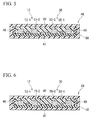
- FIG. 5 is a schematic cross-sectional view showing the control circuit apparatus 46 installed at the endoscope apparatus 1.
- FIG. 6 is a schematic cross-sectional view showing the control circuit apparatus 46. Distribution of heat emitted from first parts 13-1 and 30-1 (to be described later) is shown in FIG. 5 , and distribution of heat emitted from second parts 13-2 and 30-2 (to be described later) is shown in FIG. 6 .
- FIG. 7 is a schematic plan view showing the control circuit apparatus 46.
- the control circuit apparatus 46 includes a substrate 47, a plurality of barrier circuits (the lighting control unit 13, the imaging control unit 30), a heat-resistant resin 49 and a filler 50, and is accommodated in a placing unit 40a, which becomes a lower end when the main body 40 shown in FIG. 1 is placed on a floor surface.
- the substrate 47 is a plate-shaped member such as a glass epoxy substrate or a metal substrate, and has a predetermined interconnection structure configured to be connected to various electronic parts mounted on the substrate 47.
- the substrate 47 may have a heat radiation path configured to diffuse heat emitted from the electronic parts mounted on the substrate 47.
- An interconnection pattern or a metal base layer of the metal substrate may be employed as such a heat radiation path.
- a heat-resistant substrate is employed as the substrate 47.
- a heat-resistant temperature of the substrate 47 in the embodiment is set to 270°C.
- the lighting control unit 13 and the imaging control unit 30 are mounted on the substrate 47.
- a compartment (a first compartment 47A) on the substrate 47 in which the lighting control unit 13 is installed, and a compartment (a second compartment 47B) on the substrate 47 in which the imaging control unit 30 is installed are spaced a predetermined spacing distance from each other.
- a filling frame 48 surrounding a region including the first compartment 47A and the second compartment 47B is installed on the substrate 47.
- the lighting control unit 13 is a first barrier circuit among the plurality of barrier circuits installed at the control circuit apparatus 46 of the embodiment.
- the lighting control unit 13 is an electronic circuit configured to receive power from the battery 45 to be operated, and includes a power limiting unit 14 configured to limit the driving power supplied to the light emission unit 8 to a predetermined value or less in a state in which the light emission unit 8 is in a normal condition or a malfunction condition.
- the lighting control unit 13 is connected to the main control unit 44, and is operated according to a driving signal issued from the main control unit 44.
- the driving power supplied to the light emission unit 8 is limited by the power limiting unit 14 to satisfy an intrinsically safe explosion-proof construction (Exia) with only the lighting unit 7.
- the lighting control unit 13 is an electronic circuit having a plurality of electronic parts, and surface area of these electronic parts may be different according to specifications of the electronic parts.
- the surface area of the electronic part installed at the lighting control unit 13 has a negative correlation with a calorific value of each the electronic parts upon malfunction condition of the lighting control unit 13. That is, as the surface area of the electronic part is reduced, the calorific value upon malfunction condition is increased.
- the lighting control unit 13 has at least an electronic part (the first part 13-1) having a relatively small surface area and a relatively large assumed maximum calorific value upon malfunction condition, and an electronic part (the second part 13-2) having a relatively large surface area and a relatively small assumed maximum calorific value upon malfunction condition.
- a region in which a temperature of the substrate 47 exceeds an upper limit temperature among rated temperatures of the substrate 47 due to heat generation of the first part 13-1 becomes a substantially circular region about the first part 13-1 when seen in a thickness direction of the substrate 47.
- the temperature of the substrate 47 in the outer side rather than an outer edge of the first overheating region 47A1 is the upper limit temperature or less of the substrate 47, i.e., a temperature among the rated temperatures.
- a region (hereinafter referred to as "a second overheating region 47A2") in which a temperature of the substrate 47 exceeds the upper limit temperature among the rated temperatures of the substrate 47 due to heat generation of the second part 13-2 is a substantially circular region about the second part 13-2 when seen from the thickness direction of the substrate 47.
- the temperature of the substrate 47 in the outside rather than an outer edge of the second overheating region 47A2 is the upper limit temperature or less of the substrate 47, i.e., a temperature among the rated temperatures.
- a point PA1 disposed nearest the second compartment 47B of the outer edge of the first overheating region 47A1 and a point PA2 disposed nearest the second compartment 47B of the outer edge of the second overheating region 47A2 have substantially equal distances measured from the outer edge of the second compartment 47B.
- positions of the point PA1 and the point PA2 coincide with each other.
- both of the two points PA1 and PA2 are disposed in a gap between the first compartment 47A and the second compartment 47B.
- the disposition on the substrate 47 may be determined based on a position of the outer edge of the region in which the temperature of the substrate 47 exceeds the upper limit of the rated temperature of the substrate 47 due to heat generation.
- the imaging control unit 30 is a second barrier circuit different from the first barrier circuit among the plurality of barrier circuits installed at the control circuit apparatus 46 of the embodiment.
- the imaging control unit 30 is an electronic circuit configured to receive power from the battery 45 to be operated, and includes a deserializer circuit 31 configured to reconstruct image data based on the serial data transmitted from the serializer circuit 25 through the interconnection 26, an image processing circuit 32 configured to display the reconstructed image data on the display unit 42 (to be described later), and a power limiting unit 33 configured to limit the driving power supplied to the imaging circuit unit 19 to a predetermined value or less in a state in which the electronic part mounted on the circuit substrate 21 is in a normal state or a malfunction condition.
- the imaging control unit 30 is connected to the main control unit 44, and is operated according to the driving signal issued from the main control unit 44.
- the driving power supplied to the imaging circuit unit 19 is limited by the power limiting unit 33 to satisfy an intrinsically safe explosion-proof construction (Exia) with only the image acquisition unit 15.
- the imaging control unit 30 is an electronic circuit having a plurality of electronic parts, and surface areas of these electronic parts may be different according to specifications of the electronic parts.
- the surface area of the electronic part installed at the imaging control unit 30 has a negative correlation with a calorific value of each of the electronic parts upon malfunction condition of the imaging control unit 30. That is, as the surface area of the electronic part is reduced, the calorific value upon malfunction condition is increased.
- the imaging control unit 30 has at least an electronic part (the first part B30-1) having a relatively small surface area and a relatively large assumed maximum calorific value upon malfunction condition and an electronic part (the second part 30-2) having a relatively large surface area and a relatively small assumed maximum calorific value upon malfunction condition.
- a region (hereinafter referred to as "a first overheating region 47B 1 ") in which a temperature of the substrate 47 exceeds the upper limit temperature among the rated temperatures of the substrate 47 due to heat generation of the first part B30-1 becomes a substantially circular region about the second part when seen from the thickness direction of the substrate 47.
- the temperature of the substrate 47 in the outside rather than an outer edge of the first overheating region 47B1 is the upper limit temperature or less among the rated temperatures of the substrate 47, i.e., a temperature among the rated temperatures.
- a region (hereinafter, "a second overheating region 47B2") in which a temperature of the substrate 47 exceeds an upper limit temperature among the rated temperatures of the substrate 47 due to heat generation of the second part 30-2 is a substantially circular region about the second part 30-2 when seen from the thickness direction of the substrate 47.
- the temperature of the substrate 47 in the outside rather than an outer edge of the second overheating region 47B2 is the upper limit temperature or less among the rated temperatures of the substrate 47, i.e., a temperature among the rated temperatures.
- a point PB1 disposed nearest the first compartment 47A of the outer edge of the first overheating region 47B1 and a point PB2 disposed nearest the first compartment 47A of the outer edge of the second overheating region 47B2 have substantially equal distances measured from the outer edge of the first compartment 47A.
- positions of the point PB1 and the point PB2 coincide with each other.
- the two points PB1 and PB2 are disposed in a gap between the first compartment 47A and the second compartment 47B.
- disposition on the substrate 47 may be determined based on a position of the outer edge of the region in which the temperature of the substrate 47 exceeds the upper limit temperature among the rated temperatures of the substrate 47 due to heat generation.
- disposition of the respective barrier circuits on the substrate 47 and disposition of parts in the respective barrier circuits may be determined based on a distance from the other barrier circuit and a magnitude of heat emitted from the other barrier circuit upon malfunction condition.
- the main control unit 44 includes various electronic circuits configured to control the lighting control unit 13 and the imaging control unit 30 based on the input signal from the manipulation input unit 43.
- the heat-resistant resin 49 is formed of a resin material filled into the inside of the filling frame 48 to cover the lighting control unit 13 and the imaging control unit 30.
- the heat-resistant resin 49 has a higher heat resistance than the substrate 47.
- An inorganic bonding agent such as alumina may be used as a material of the heat-resistant resin 49.
- a dimension of the heat-resistant resin 49 is set such that a temperature of an interface of the outer surface of the heat-resistant resin 49 in contact with the filler 50 is a rated upper limit temperature or less of the filler 50.
- a dimension of the heat-resistant resin 49 may be set in consideration of heat generation from the other barrier circuit.
- the filler 50 has substantially the same heat resistance as the substrate 47, and covers the entire substrate 47, the lighting control unit 13 and the imaging control unit 30 as well as the heat-resistant resin 49.
- a heat-resistant temperature of the filler 50 is set to 200°C.
- the filler 50 may have higher flexibility than the heat-resistant resin 49, and the filler 50 is formed of a material having a low permeability of a gas to prevent a combustible gas from passing through the filler 50 and arriving at the electronic part on the heat-resistant resin 49 or the substrate 47.
- the respective barrier circuits (the lighting control unit 13, the imaging control unit 30, and the other barrier circuit) installed at the control circuit apparatus 46 may have different specifications such as rated driving voltages.
- the plurality of barrier circuits installed on the substrate 47 are electrically separated from each other. A magnitude of power supplied from the battery 45 to the respective barrier circuits is limited by the power limiting units 14 and 33.
- all of the first overheating regions 47A1 and 47B1 and the second overheating regions 47A2 and 47B2 have outer edges disposed between the first compartment 47A and the second compartment 47B.
- thermal influence due to malfunction condition of the lighting control unit 13 does not reach the imaging control unit 30, and thermal influence due to malfunction of the imaging control unit 30 does not reach the lighting control unit 13.
- circuit disposition in which the outer edge of the first overheating region 47A1 and the outer edge of the second overheating region 47A2 and the outer edge of the first overheating region 47B1 and the outer edge of the second overheating region 47B2 approach each other to an extreme while maintaining a predetermined spacing distance becomes circuit disposition in which a mounting area on the substrate 47 is minimized.
- the predetermined spacing distance is set
- the substrate 47 on which the plurality of barrier circuits are mounted can be miniaturized.
- the circuit disposition can be preferably used in an explosive atmosphere.
- the substrate 47 and the respective barrier circuits are covered by the heat-resistant resin 49, probability of the heat-resistant resin 49 breaking due to heat generation from the lighting control unit 13 or the imaging control unit 30 is reduced, and probability of a combustible gas coming in contact with the lighting control unit 13 or the imaging control unit 30 is reduced.
- the substrate 47, the lighting control unit 13, the imaging control unit 30, and the heat-resistant resin 49 are hermetically sealed by the filler 50, even when cracks are generated in the heat-resistant resin 49 due to thermal expansion of bubbles in the heat-resistant resin 49, air tightness is maintained by the filler 50, and probability of the combustible gas coming in contact with the lighting control unit 13 or the imaging control unit 30 can be suppressed to a low level.
- FIG. 8 is a schematic cross-sectional view showing a control circuit apparatus of the modified example.
- a shape of the filling frame 48 is different from the filling frame 48 of the control circuit apparatus 46 of the first embodiment.
- a height dimension in a thickness direction of the substrate 47 corresponds to a height dimension of the electronic part constituting each of the respective barrier circuits (the lighting control unit 13 and the imaging control unit 30).
- the height dimension of the filling frame 48 is equal to a height dimension of the electronic parts ( FIG. 8 shows reference numerals 13-2a and 30-2b) having the largest height dimension upon mounting, among the electronic parts constituting the respective barrier circuits. For this reason, an upper end of the electronic part having the largest dimension upon mounting is in contact with the filler 50, while not covered by the heat-resistant resin 49.
- a charge amount of the heat-resistant resin 49 can be reduced in comparison with that of the first embodiment, and the control circuit apparatus 46 can have a compact size and a light weight.
- the electronic part having the large height dimension upon mounting tends to be a part having a large surface area in comparison with the other electronic parts and a relatively small calorific value in comparison with the electronic part mounted on the substrate 47. For this reason, there is no crack generated from the filler 50 due to heat generation, and the hermetically sealed state can be sufficiently maintained by the filler 50.
- a thickness dimension (a dimension measured in the thickness direction of the substrate 47) of the heat-resistant resin 49 may be reduced such that a portion of a side surface disposed at the upper end side of the electronic part comes in contact with the filler 50.
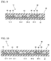
- FIG. 9 is a schematic cross-sectional view showing a control circuit apparatus of the modified example.
- a shape of the filling frame 48 is different from that of the filling frame 48 of the control circuit apparatus 46 of the first embodiment.
- the filling frame 48 is separately installed with respect to the lighting control unit 13 and an imaging control circuit 30, and the electronic part that does not exceed a heat-resistant temperature of the filler 50 and the substrate 47 even when the heat is generated to a maximum calorific value (an assumed maximum calorific value) assumed upon malfunction condition is disposed outside each of the filling frames 48.
- an amount of the heat-resistant resin 49 required to cover the electronic part may be smaller.
- the electronic parts which are not covered by the heat-resistant resin 49 are in contact with the filler 50 instead of the heat-resistant resin 49.
- control circuit apparatus 46 can be reduced in weight in comparison with that in the first embodiment.
- FIG. 10 is a schematic cross-sectional view showing a control circuit apparatus of the modified example.
- the plurality of filling frames 48 are installed on the substrate 47, the respective filling frames 48 are configured to surround the electronic parts (for example, the first parts 13-1 and 30-1 described in the first embodiment) having a relatively large calorific value.
- the heat-resistant resin 49 is filled in each of the filling frames 48.
- circuit disposition on the substrate 47 can be optimized. Optimization of the circuit disposition in the modified example is to use a capacity of each of the filling frames 48 as a minimal capacity configured to cover the electronic parts having a large calorific value, similarly to the modified example 2, and to use the heat-resistant resin 49 filled in each of the filling frames 48 as a balance weight configured to adjust a center position of the main body 40.
- the barrier circuit in FIG. 10 , the lighting control unit 13
- the second barrier circuit for example, the imaging control unit 30
- the barrier circuit in FIG. 10 , the lighting control unit 13
- the barrier circuit having a large number of parts having a relatively large calorific value should be covered using a larger amount of heat-resistant resin 49 than the barrier circuit having a small number of parts having a relatively large calorific value, increasing the weight thereof.
- the endoscope apparatus 1 upon design of the endoscope apparatus 1, in addition to adjustment of a center position by disposition of components other than the control circuit apparatus 46, adjustment of the position in the main body 40 of the control circuit apparatus 46 and a position of the heat-resistant resin 49 on the substrate 47 is performed, and a center of the endoscope apparatus 1 can be adjusted to be at a predetermined position.
- a ratio of the weight of the heat-resistant resin in the total weight of the main body 40 may be about 30% to 40%.
- a ratio of the weight of the heat-resistant resin 49 in the total weight of the main body 40 may be about 20% to 30%.
- the position of the heat-resistant resin 49 in the first barrier circuit (for example, the lighting control unit 13) and the position of the heat-resistant resin 49 in the second barrier circuit (for example, the imaging control unit 30) is possible to be set independently from each other.
- the weight balance of the endoscope apparatus 1 is possible to be easily accomplished.
- the position of the heat-resistant resin 49 is possible to be adjusted to set the weight balance of the endoscope apparatus 1, when an instrument configuration in the main body 40 is limited due to deviation of the weight balance of the endoscope apparatus 1 from a very appropriate balance, the limit is possible to be attenuated.
- a distance from the outer edge of the second compartment 47B to the point PA1 is substantially equal to a distance from the outer edge of the second compartment 47B to the point PA2.
- FIG. 11 as an example of such a case, the case in which the entire second part 13-2 is inserted into the first overheating region 47A1 when seen from the thickness direction of the substrate 47 is exemplified.
- the second overheating region 47A2 becomes a circular outer edge about the heat generation center H.
- a distance from the outer edge of the second compartment 47B to the point PA1 is substantially equal to a distance from the outer edge of the second compartment 47B to the point PA2.
- the design change is not limited to the example.
Landscapes
- Physics & Mathematics (AREA)
- Engineering & Computer Science (AREA)
- Astronomy & Astrophysics (AREA)
- General Physics & Mathematics (AREA)
- Optics & Photonics (AREA)
- Multimedia (AREA)
- Signal Processing (AREA)
- Microelectronics & Electronic Packaging (AREA)
- Endoscopes (AREA)
- Instruments For Viewing The Inside Of Hollow Bodies (AREA)
Claims (5)
- Steuerschaltungsgerät (46) für ein Endoskopgerät, das umfasst:ein Substrat (47);eine Mehrzahl von auf dem Substrat (47) angebrachten Barriereschaltungen (13, 30);ein wärmebeständiges Harz (49), das dazu eingerichtet ist, zumindest einen Abschnitt einer jeden der Mehrzahl von Barriereschaltungen (13, 30) zu bedecken; undeinen Füller (50), der dazu eingerichtet ist, das Substrat (47), die Mehrzahl von Barriereschaltungen (13, 30) und das wärmebeständige Harz (49) zu bedecken, wobeiein erster Abschnitt (47A), in dem eine erste Barriereschaltung der Mehrzahl von Barriereschaltungen (13, 30) angeordnet ist, und ein zweiter Abschnitt (47B), der zu dem ersten Abschnitt benachbart ist und in dem eine zweite Barriereschaltung der Mehrzahl von Barriereschaltungen (13, 30), die sich von der ersten Barriereschaltung unterscheidet, angeordnet ist, auf dem Substrat (47) gebildet sind,die erste Barriereschaltung (13) eine Beleuchtungssteuereinheit ist,die zweite Barriereschaltung (30) eine Bildgebungssteuereinheit ist,die ersten und zweiten Abschnitte (47A, 47B) durch den Füller (50) umschlossen sind,die erste Barriereschaltung (13) ein erstes elektronisches Teil (13-1) und ein zweites elektronisches Teil (13-2) hat und Oberflächenbereiche der ersten und zweiten elektronischen Teile (13-1, 13-2) bei einer Fehlfunktion der ersten Barriereschaltung (13) negative Korrelationen mit kalorischen Werten der jeweiligen ersten und zweiten elektronischen Teile (13-1, 13-2) haben,das erste elektronische Teil (13-1) der ersten Barriereschaltung (13) an einer Position angeordnet ist, die weiter entfernt von dem zweiten Abschnitt (47B) ist als das zweite elektronische Teil (13-2) der ersten Barriereschaltung (13), so dass Abstände von einem äußeren Rand des zweiten Abschnitts (47B) zu einem dem zweiten Abschnitt (47B) nächstgelegenen Punkt eines äußeren Rands eines Bereichs, in dem eine Temperatur des Substrats (47) aufgrund einer fehlerhaften Wärmeerzeugung des ersten elektronischen Teils (13-1) der ersten Barriereschaltung (13) eine obere Grenztemperatur aus bewerteten Temperaturen des Substrats (47) überschreitet, und einem dem zweiten Abschnitt (47B) nächstgelegenen Punkt eines äußeren Rands eines Bereichs, in dem eine Temperatur des Substrats (47) aufgrund einer fehlerhaften Wärmeerzeugung des zweiten elektronischen Teils (13-2) der ersten Barriereschaltung (13) eine obere Grenztemperatur aus bewerteten Temperaturen des Substrats (47) überschreitet, einander im Wesentlichen gleichen,die zweite Barriereschaltung (30) ein erstes elektronisches Teil (30-1) und ein zweites elektronisches Teil (30-2) hat und Oberflächenbereiche der ersten und zweiten elektronischen Teile (30-1, 30-2) bei einer Fehlfunktion der zweiten Barriereschaltung (30) negative Korrelationen mit kalorischen Werten der der jeweiligen ersten und zweiten elektronischen Teile (30-1, 30-2) haben,das erste elektronische Teil (30-1) der zweiten Barriereschaltung (30) an einer Position angeordnet ist, die weiter entfernt von dem ersten Abschnitt (47A) ist als das zweite elektronische Teil (30-2) der zweiten Barriereschaltung (30), so dass Abstände von einem äußeren Rand des ersten Abschnitts (47A) zu einem dem ersten Abschnitt (47A) nächstgelegenen Punkt eines äußeren Rands eines Bereichs, in dem eine Temperatur des Substrats (47) aufgrund einer fehlerhaften Wärmeerzeugung des ersten elektronischen Teils (30-1) der zweiten Barriereschaltung (30) eine obere Grenztemperatur aus bewerteten Temperaturen des Substrats (47) überschreitet, und einem dem ersten Abschnitt (47A) nächstgelegenen Punkt eines äußeren Rands eines Bereichs, in dem eine Temperatur des Substrats (47) aufgrund einer fehlerhaften Wärmeerzeugung des zweiten elektronischen Teils (30-2) der zweiten Barriereschaltung (30) eine obere Grenztemperatur aus bewerteten Temperaturen des Substrats (47) überschreitet, einander im Wesentlichen gleichen.
- Steuerschaltungsgerät (46) nach Anspruch 1, das ferner umfasst
einen Füllrahmen (48), der an einer von beiden Oberflächen in der Dickenrichtung des Substrats (47) ausgebildet ist, auf dem die erste Barriereschaltung (13) angebracht ist und in den das wärmebeständige Harz (49) eingefüllt ist,
wobei der Füllrahmen (48) so ausgebildet ist, dass er zumindest das erste elektronische Teil (13-1) in der ersten Barriereschaltung (13) umgibt. - Steuerschaltungsgerät (46) nach Anspruch 1, das ferner umfasst:einen ersten Füllrahmen, der an einer von beiden Oberflächen in der Dickenrichtung des Substrats (47) ausgebildet ist, in dem die erste Barriereschaltung (13) angebracht ist und in den das wärmebeständige Harz (49) eingefüllt ist;einen zweiten Füllrahmen, der an einer von beiden Oberflächen in der Dickenrichtung des Substrats (47) ausgebildet ist, in dem die zweite Barriereschaltung (30) angebracht ist und in den das wärmebeständige Harz (49) eingefüllt ist;wobei der erste Füllrahmen dazu eingerichtet ist, zumindest das erste elektronische Teil (13-1) der ersten Barriereschaltung (13) zu umgeben, undder zweite Füllrahmen dazu eingerichtet ist, zumindest das erste elektronische Teil (30-1) der zweiten Barriereschaltung (30) zu umgeben.
- Endoskopgerät (1), das umfasst:das Steuerschaltungsgerät (46) gemäß Anspruch 1;einen Hauptkörper (40), der das Steuerschaltungsgerät (46) in sich aufnimmt;einen langen Einführabschnitt (2), der ein an dem Hauptkörper (40) befestigtes Ende hat;eine Bildgebungseinheit (17), die an dem anderen Ende des Einführabschnitts (2) installiert und dazu eingerichtet ist, ein Objekt abzubilden;eine Beleuchtungseinheit (7), die an dem anderen Ende des Einführabschnitts (2) installiert und dazu eingerichtet ist, Licht auf das Objekt zu strahlen; undeine Steuereinheit (46), die an dem Hauptkörper (40) installiert und dazu eingerichtet ist, die Bildgebungseinheit (17) und die Beleuchtungseinheit (7) zu steuern,wobei die Steuereinheit (46) die Bildgebungssteuereinheit (30) umfasst, die dazu eingerichtet ist, Energie von einer Barriereschaltung der Mehrzahl von Barriereschaltungen zu empfangen und die Bildgebungseinheit (17) zu betreiben, unddie Beleuchtungssteuereinheit (13) dazu eingerichtet ist, Energie von einer anderen Barriereschaltung der Mehrzahl von Barriereschaltungen zu empfangen und die Beleuchtungseinheit (7) zu betreiben.
- Endoskopgerät (1) gemäß Anspruch 4, bei dem das wärmebeständige Harz (49) an zwei oder mehr unterschiedlichen Stellen auf dem Substrat (47) angeordnet ist.
Applications Claiming Priority (1)
| Application Number | Priority Date | Filing Date | Title |
|---|---|---|---|
| JP2011287127A JP5977518B2 (ja) | 2011-12-28 | 2011-12-28 | 制御回路装置及び内視鏡装置 |
Publications (2)
| Publication Number | Publication Date |
|---|---|
| EP2610663A1 EP2610663A1 (de) | 2013-07-03 |
| EP2610663B1 true EP2610663B1 (de) | 2016-06-15 |
Family
ID=47709768
Family Applications (1)
| Application Number | Title | Priority Date | Filing Date |
|---|---|---|---|
| EP12199007.1A Not-in-force EP2610663B1 (de) | 2011-12-28 | 2012-12-21 | Steuerschaltungsvorrichtung und Endoskopvorrichtung |
Country Status (4)
| Country | Link |
|---|---|
| US (1) | US9451215B2 (de) |
| EP (1) | EP2610663B1 (de) |
| JP (1) | JP5977518B2 (de) |
| CN (1) | CN103185961B (de) |
Families Citing this family (5)
| Publication number | Priority date | Publication date | Assignee | Title |
|---|---|---|---|---|
| USD792301S1 (en) * | 2015-09-22 | 2017-07-18 | Hangzhou Ezviz Network Co., Ltd. | Video camera |
| USD861518S1 (en) * | 2017-04-27 | 2019-10-01 | Shenzhen Deepsea Voyage Investment Co., Ltd. | Wifi borescope inspection camera |
| USD860016S1 (en) * | 2017-04-27 | 2019-09-17 | Shenzhen Deepsea Voyage Investment Co., Ltd. | Wifi borescope inspection camera |
| USD828862S1 (en) * | 2017-06-06 | 2018-09-18 | Ningbo Hi-Tech Zone Cvs Borescope Tech Co., Ltd. | Borescope |
| CN111273593B (zh) * | 2020-03-23 | 2021-09-21 | 珠海嘉润医用影像科技有限公司 | 内窥镜智能控制电路 |
Family Cites Families (16)
| Publication number | Priority date | Publication date | Assignee | Title |
|---|---|---|---|---|
| JP2549398Y2 (ja) * | 1992-10-15 | 1997-09-30 | ティーディーケイ株式会社 | 大電流用ノイズフィルタ |
| GB9417235D0 (en) * | 1994-08-26 | 1994-10-19 | Measurement Tech Ltd | Electrical safety barriers |
| JPH10190199A (ja) | 1996-12-26 | 1998-07-21 | Sanyo Electric Co Ltd | 回路基板の樹脂被覆方法 |
| JP4317297B2 (ja) * | 1999-09-30 | 2009-08-19 | フジノン株式会社 | 電子内視鏡装置 |
| KR100822542B1 (ko) * | 2001-03-14 | 2008-04-16 | 이비덴 가부시키가이샤 | 다층 프린트 배선판 |
| JP2002306406A (ja) * | 2001-04-10 | 2002-10-22 | Asahi Optical Co Ltd | 電子内視鏡用クランプ回路 |
| JP2004000335A (ja) * | 2002-05-31 | 2004-01-08 | Olympus Corp | 電子内視鏡装置 |
| JP4436631B2 (ja) * | 2003-08-04 | 2010-03-24 | オリンパス株式会社 | カプセル内視鏡 |
| JP4648717B2 (ja) * | 2005-02-04 | 2011-03-09 | Hoya株式会社 | Ccdの破損防止システム |
| TWI303094B (en) * | 2005-03-16 | 2008-11-11 | Yamaha Corp | Semiconductor device, method for manufacturing semiconductor device, and cover frame |
| JP4855059B2 (ja) * | 2005-12-08 | 2012-01-18 | オリンパス株式会社 | 内視鏡装置 |
| JP4757044B2 (ja) * | 2006-01-27 | 2011-08-24 | オリンパス株式会社 | 防爆機器駆動装置 |
| JP2009059801A (ja) * | 2007-08-30 | 2009-03-19 | Toshiba Corp | 電子機器 |
| JP4709870B2 (ja) * | 2008-04-07 | 2011-06-29 | オリンパス株式会社 | 撮像装置 |
| JP5018765B2 (ja) * | 2008-12-26 | 2012-09-05 | 株式会社Jvcケンウッド | 防爆対応無線機の充填剤の充填構造。 |
| SM200900016B (it) * | 2009-03-12 | 2011-11-11 | T & A Tecnologie E Ambiente S A | Dispositivo per videoispezione in aree con possibile presenza di atmosfera esplosiva |
-
2011
- 2011-12-28 JP JP2011287127A patent/JP5977518B2/ja not_active Expired - Fee Related
-
2012
- 2012-12-21 EP EP12199007.1A patent/EP2610663B1/de not_active Not-in-force
- 2012-12-21 US US13/723,809 patent/US9451215B2/en not_active Expired - Fee Related
- 2012-12-25 CN CN201210573192.6A patent/CN103185961B/zh not_active Expired - Fee Related
Also Published As
| Publication number | Publication date |
|---|---|
| JP2013137347A (ja) | 2013-07-11 |
| US9451215B2 (en) | 2016-09-20 |
| EP2610663A1 (de) | 2013-07-03 |
| CN103185961B (zh) | 2016-07-20 |
| US20130169776A1 (en) | 2013-07-04 |
| JP5977518B2 (ja) | 2016-08-24 |
| CN103185961A (zh) | 2013-07-03 |
Similar Documents
| Publication | Publication Date | Title |
|---|---|---|
| US9451215B2 (en) | Control circuit apparatus and endoscope apparatus | |
| CN103874450B (zh) | 镜框组件以及具备镜框组件的内窥镜 | |
| AU2012323462B2 (en) | Cooled aerial camera | |
| US10095021B2 (en) | Endoscope | |
| US11122969B2 (en) | Endoscopic device | |
| US20150190039A1 (en) | Imaging module and endoscope device | |
| CN107529977B (zh) | 光源装置 | |
| CN103026563A (zh) | 带有耐压地封装的子壳体的电路板 | |
| US20120069956A1 (en) | Computed tomography detector module | |
| US12489097B2 (en) | Light emitting module combining enhanced safety features and thermal management | |
| EP2987448A1 (de) | Bilderfassungsvorrichtung und elektronisches endoskop | |
| JP4757044B2 (ja) | 防爆機器駆動装置 | |
| JPWO2015045456A1 (ja) | 内視鏡装置 | |
| CN106132272B (zh) | 内窥镜用防雾单元和内窥镜系统 | |
| US12078561B2 (en) | Optical sensor and optical sensor module | |
| CN107251344A (zh) | 光学模块 | |
| US20170322421A1 (en) | Intrinsically safe safety goggles with data display, user input and data communication | |
| CN107710729A (zh) | 摄像单元、摄像模块以及内窥镜 | |
| CN104024920B (zh) | 发光模块 | |
| DK2708018T3 (da) | Optisk optageindretning | |
| JP6384220B2 (ja) | レーザユニット | |
| JP2007228296A (ja) | 撮像装置 | |
| JP2022155009A (ja) | 放射線撮影装置及び放射線撮影システム | |
| WO2021260863A1 (ja) | 電子モジュール、電子モジュールの製造方法および内視鏡 | |
| CN101563635A (zh) | 透镜装置和发光二极管显示装置 |
Legal Events
| Date | Code | Title | Description |
|---|---|---|---|
| PUAI | Public reference made under article 153(3) epc to a published international application that has entered the european phase |
Free format text: ORIGINAL CODE: 0009012 |
|
| AK | Designated contracting states |
Kind code of ref document: A1 Designated state(s): AL AT BE BG CH CY CZ DE DK EE ES FI FR GB GR HR HU IE IS IT LI LT LU LV MC MK MT NL NO PL PT RO RS SE SI SK SM TR |
|
| AX | Request for extension of the european patent |
Extension state: BA ME |
|
| 17P | Request for examination filed |
Effective date: 20131010 |
|
| RBV | Designated contracting states (corrected) |
Designated state(s): AL AT BE BG CH CY CZ DE DK EE ES FI FR GB GR HR HU IE IS IT LI LT LU LV MC MK MT NL NO PL PT RO RS SE SI SK SM TR |
|
| GRAP | Despatch of communication of intention to grant a patent |
Free format text: ORIGINAL CODE: EPIDOSNIGR1 |
|
| RIC1 | Information provided on ipc code assigned before grant |
Ipc: G02B 23/24 20060101AFI20151218BHEP Ipc: H04N 7/18 20060101ALI20151218BHEP |
|
| INTG | Intention to grant announced |
Effective date: 20160119 |
|
| GRAS | Grant fee paid |
Free format text: ORIGINAL CODE: EPIDOSNIGR3 |
|
| GRAA | (expected) grant |
Free format text: ORIGINAL CODE: 0009210 |
|
| AK | Designated contracting states |
Kind code of ref document: B1 Designated state(s): AL AT BE BG CH CY CZ DE DK EE ES FI FR GB GR HR HU IE IS IT LI LT LU LV MC MK MT NL NO PL PT RO RS SE SI SK SM TR |
|
| REG | Reference to a national code |
Ref country code: CH Ref legal event code: EP Ref country code: GB Ref legal event code: FG4D |
|
| REG | Reference to a national code |
Ref country code: IE Ref legal event code: FG4D |
|
| REG | Reference to a national code |
Ref country code: AT Ref legal event code: REF Ref document number: 806788 Country of ref document: AT Kind code of ref document: T Effective date: 20160715 |
|
| REG | Reference to a national code |
Ref country code: DE Ref legal event code: R096 Ref document number: 602012019532 Country of ref document: DE |
|
| RAP2 | Party data changed (patent owner data changed or rights of a patent transferred) |
Owner name: OLYMPUS CORPORATION |
|
| RAP2 | Party data changed (patent owner data changed or rights of a patent transferred) |
Owner name: OLYMPUS CORPORATION |
|
| REG | Reference to a national code |
Ref country code: LT Ref legal event code: MG4D |
|
| REG | Reference to a national code |
Ref country code: NL Ref legal event code: MP Effective date: 20160615 |
|
| PG25 | Lapsed in a contracting state [announced via postgrant information from national office to epo] |
Ref country code: LT Free format text: LAPSE BECAUSE OF FAILURE TO SUBMIT A TRANSLATION OF THE DESCRIPTION OR TO PAY THE FEE WITHIN THE PRESCRIBED TIME-LIMIT Effective date: 20160615 Ref country code: NO Free format text: LAPSE BECAUSE OF FAILURE TO SUBMIT A TRANSLATION OF THE DESCRIPTION OR TO PAY THE FEE WITHIN THE PRESCRIBED TIME-LIMIT Effective date: 20160915 Ref country code: FI Free format text: LAPSE BECAUSE OF FAILURE TO SUBMIT A TRANSLATION OF THE DESCRIPTION OR TO PAY THE FEE WITHIN THE PRESCRIBED TIME-LIMIT Effective date: 20160615 |
|
| RIN2 | Information on inventor provided after grant (corrected) |
Inventor name: DOI, AYUMI |
|
| REG | Reference to a national code |
Ref country code: AT Ref legal event code: MK05 Ref document number: 806788 Country of ref document: AT Kind code of ref document: T Effective date: 20160615 |
|
| PG25 | Lapsed in a contracting state [announced via postgrant information from national office to epo] |
Ref country code: GR Free format text: LAPSE BECAUSE OF FAILURE TO SUBMIT A TRANSLATION OF THE DESCRIPTION OR TO PAY THE FEE WITHIN THE PRESCRIBED TIME-LIMIT Effective date: 20160916 Ref country code: NL Free format text: LAPSE BECAUSE OF FAILURE TO SUBMIT A TRANSLATION OF THE DESCRIPTION OR TO PAY THE FEE WITHIN THE PRESCRIBED TIME-LIMIT Effective date: 20160615 Ref country code: LV Free format text: LAPSE BECAUSE OF FAILURE TO SUBMIT A TRANSLATION OF THE DESCRIPTION OR TO PAY THE FEE WITHIN THE PRESCRIBED TIME-LIMIT Effective date: 20160615 Ref country code: SE Free format text: LAPSE BECAUSE OF FAILURE TO SUBMIT A TRANSLATION OF THE DESCRIPTION OR TO PAY THE FEE WITHIN THE PRESCRIBED TIME-LIMIT Effective date: 20160615 Ref country code: RS Free format text: LAPSE BECAUSE OF FAILURE TO SUBMIT A TRANSLATION OF THE DESCRIPTION OR TO PAY THE FEE WITHIN THE PRESCRIBED TIME-LIMIT Effective date: 20160615 Ref country code: HR Free format text: LAPSE BECAUSE OF FAILURE TO SUBMIT A TRANSLATION OF THE DESCRIPTION OR TO PAY THE FEE WITHIN THE PRESCRIBED TIME-LIMIT Effective date: 20160615 |
|
| PG25 | Lapsed in a contracting state [announced via postgrant information from national office to epo] |
Ref country code: EE Free format text: LAPSE BECAUSE OF FAILURE TO SUBMIT A TRANSLATION OF THE DESCRIPTION OR TO PAY THE FEE WITHIN THE PRESCRIBED TIME-LIMIT Effective date: 20160615 Ref country code: IS Free format text: LAPSE BECAUSE OF FAILURE TO SUBMIT A TRANSLATION OF THE DESCRIPTION OR TO PAY THE FEE WITHIN THE PRESCRIBED TIME-LIMIT Effective date: 20161015 Ref country code: IT Free format text: LAPSE BECAUSE OF FAILURE TO SUBMIT A TRANSLATION OF THE DESCRIPTION OR TO PAY THE FEE WITHIN THE PRESCRIBED TIME-LIMIT Effective date: 20160615 Ref country code: SK Free format text: LAPSE BECAUSE OF FAILURE TO SUBMIT A TRANSLATION OF THE DESCRIPTION OR TO PAY THE FEE WITHIN THE PRESCRIBED TIME-LIMIT Effective date: 20160615 Ref country code: RO Free format text: LAPSE BECAUSE OF FAILURE TO SUBMIT A TRANSLATION OF THE DESCRIPTION OR TO PAY THE FEE WITHIN THE PRESCRIBED TIME-LIMIT Effective date: 20160615 Ref country code: CZ Free format text: LAPSE BECAUSE OF FAILURE TO SUBMIT A TRANSLATION OF THE DESCRIPTION OR TO PAY THE FEE WITHIN THE PRESCRIBED TIME-LIMIT Effective date: 20160615 |
|
| PG25 | Lapsed in a contracting state [announced via postgrant information from national office to epo] |
Ref country code: ES Free format text: LAPSE BECAUSE OF FAILURE TO SUBMIT A TRANSLATION OF THE DESCRIPTION OR TO PAY THE FEE WITHIN THE PRESCRIBED TIME-LIMIT Effective date: 20160615 Ref country code: AT Free format text: LAPSE BECAUSE OF FAILURE TO SUBMIT A TRANSLATION OF THE DESCRIPTION OR TO PAY THE FEE WITHIN THE PRESCRIBED TIME-LIMIT Effective date: 20160615 Ref country code: PT Free format text: LAPSE BECAUSE OF FAILURE TO SUBMIT A TRANSLATION OF THE DESCRIPTION OR TO PAY THE FEE WITHIN THE PRESCRIBED TIME-LIMIT Effective date: 20161017 Ref country code: PL Free format text: LAPSE BECAUSE OF FAILURE TO SUBMIT A TRANSLATION OF THE DESCRIPTION OR TO PAY THE FEE WITHIN THE PRESCRIBED TIME-LIMIT Effective date: 20160615 Ref country code: BE Free format text: LAPSE BECAUSE OF FAILURE TO SUBMIT A TRANSLATION OF THE DESCRIPTION OR TO PAY THE FEE WITHIN THE PRESCRIBED TIME-LIMIT Effective date: 20160615 Ref country code: SM Free format text: LAPSE BECAUSE OF FAILURE TO SUBMIT A TRANSLATION OF THE DESCRIPTION OR TO PAY THE FEE WITHIN THE PRESCRIBED TIME-LIMIT Effective date: 20160615 |
|
| REG | Reference to a national code |
Ref country code: DE Ref legal event code: R097 Ref document number: 602012019532 Country of ref document: DE |
|
| PLBE | No opposition filed within time limit |
Free format text: ORIGINAL CODE: 0009261 |
|
| STAA | Information on the status of an ep patent application or granted ep patent |
Free format text: STATUS: NO OPPOSITION FILED WITHIN TIME LIMIT |
|
| 26N | No opposition filed |
Effective date: 20170316 |
|
| PG25 | Lapsed in a contracting state [announced via postgrant information from national office to epo] |
Ref country code: DK Free format text: LAPSE BECAUSE OF FAILURE TO SUBMIT A TRANSLATION OF THE DESCRIPTION OR TO PAY THE FEE WITHIN THE PRESCRIBED TIME-LIMIT Effective date: 20160615 |
|
| REG | Reference to a national code |
Ref country code: CH Ref legal event code: PL |
|
| GBPC | Gb: european patent ceased through non-payment of renewal fee |
Effective date: 20161221 |
|
| PG25 | Lapsed in a contracting state [announced via postgrant information from national office to epo] |
Ref country code: SI Free format text: LAPSE BECAUSE OF FAILURE TO SUBMIT A TRANSLATION OF THE DESCRIPTION OR TO PAY THE FEE WITHIN THE PRESCRIBED TIME-LIMIT Effective date: 20160615 |
|
| PG25 | Lapsed in a contracting state [announced via postgrant information from national office to epo] |
Ref country code: MC Free format text: LAPSE BECAUSE OF FAILURE TO SUBMIT A TRANSLATION OF THE DESCRIPTION OR TO PAY THE FEE WITHIN THE PRESCRIBED TIME-LIMIT Effective date: 20160615 |
|
| REG | Reference to a national code |
Ref country code: FR Ref legal event code: ST Effective date: 20170831 |
|
| REG | Reference to a national code |
Ref country code: IE Ref legal event code: MM4A |
|
| PG25 | Lapsed in a contracting state [announced via postgrant information from national office to epo] |
Ref country code: CH Free format text: LAPSE BECAUSE OF NON-PAYMENT OF DUE FEES Effective date: 20161231 Ref country code: LU Free format text: LAPSE BECAUSE OF NON-PAYMENT OF DUE FEES Effective date: 20161221 Ref country code: LI Free format text: LAPSE BECAUSE OF NON-PAYMENT OF DUE FEES Effective date: 20161231 Ref country code: FR Free format text: LAPSE BECAUSE OF NON-PAYMENT OF DUE FEES Effective date: 20170102 |
|
| PG25 | Lapsed in a contracting state [announced via postgrant information from national office to epo] |
Ref country code: GB Free format text: LAPSE BECAUSE OF NON-PAYMENT OF DUE FEES Effective date: 20161221 Ref country code: IE Free format text: LAPSE BECAUSE OF NON-PAYMENT OF DUE FEES Effective date: 20161221 |
|
| PG25 | Lapsed in a contracting state [announced via postgrant information from national office to epo] |
Ref country code: CY Free format text: LAPSE BECAUSE OF FAILURE TO SUBMIT A TRANSLATION OF THE DESCRIPTION OR TO PAY THE FEE WITHIN THE PRESCRIBED TIME-LIMIT Effective date: 20160615 Ref country code: HU Free format text: LAPSE BECAUSE OF FAILURE TO SUBMIT A TRANSLATION OF THE DESCRIPTION OR TO PAY THE FEE WITHIN THE PRESCRIBED TIME-LIMIT; INVALID AB INITIO Effective date: 20121221 |
|
| PG25 | Lapsed in a contracting state [announced via postgrant information from national office to epo] |
Ref country code: MK Free format text: LAPSE BECAUSE OF FAILURE TO SUBMIT A TRANSLATION OF THE DESCRIPTION OR TO PAY THE FEE WITHIN THE PRESCRIBED TIME-LIMIT Effective date: 20160615 |
|
| PG25 | Lapsed in a contracting state [announced via postgrant information from national office to epo] |
Ref country code: BG Free format text: LAPSE BECAUSE OF FAILURE TO SUBMIT A TRANSLATION OF THE DESCRIPTION OR TO PAY THE FEE WITHIN THE PRESCRIBED TIME-LIMIT Effective date: 20160615 |
|
| PG25 | Lapsed in a contracting state [announced via postgrant information from national office to epo] |
Ref country code: MT Free format text: LAPSE BECAUSE OF NON-PAYMENT OF DUE FEES Effective date: 20161221 |
|
| PG25 | Lapsed in a contracting state [announced via postgrant information from national office to epo] |
Ref country code: AL Free format text: LAPSE BECAUSE OF FAILURE TO SUBMIT A TRANSLATION OF THE DESCRIPTION OR TO PAY THE FEE WITHIN THE PRESCRIBED TIME-LIMIT Effective date: 20160615 Ref country code: TR Free format text: LAPSE BECAUSE OF FAILURE TO SUBMIT A TRANSLATION OF THE DESCRIPTION OR TO PAY THE FEE WITHIN THE PRESCRIBED TIME-LIMIT Effective date: 20160615 |
|
| PGFP | Annual fee paid to national office [announced via postgrant information from national office to epo] |
Ref country code: DE Payment date: 20181210 Year of fee payment: 7 |
|
| REG | Reference to a national code |
Ref country code: DE Ref legal event code: R119 Ref document number: 602012019532 Country of ref document: DE |
|
| PG25 | Lapsed in a contracting state [announced via postgrant information from national office to epo] |
Ref country code: DE Free format text: LAPSE BECAUSE OF NON-PAYMENT OF DUE FEES Effective date: 20200701 |