EP2610324B1 - Appareil destiné à la pyrolyse d'une substance charbonneuse - Google Patents
Appareil destiné à la pyrolyse d'une substance charbonneuse Download PDFInfo
- Publication number
- EP2610324B1 EP2610324B1 EP10856057.4A EP10856057A EP2610324B1 EP 2610324 B1 EP2610324 B1 EP 2610324B1 EP 10856057 A EP10856057 A EP 10856057A EP 2610324 B1 EP2610324 B1 EP 2610324B1
- Authority
- EP
- European Patent Office
- Prior art keywords
- gas
- coal
- kiln body
- decomposition
- flame gas
- Prior art date
- Legal status (The legal status is an assumption and is not a legal conclusion. Google has not performed a legal analysis and makes no representation as to the accuracy of the status listed.)
- Active
Links
- 239000003245 coal Substances 0.000 title claims description 72
- 238000000197 pyrolysis Methods 0.000 title description 2
- 239000000126 substance Substances 0.000 title description 2
- 238000000354 decomposition reaction Methods 0.000 claims description 32
- 238000010438 heat treatment Methods 0.000 claims description 29
- 230000017525 heat dissipation Effects 0.000 claims description 15
- 239000000446 fuel Substances 0.000 claims description 10
- 239000007789 gas Substances 0.000 description 75
- 238000000034 method Methods 0.000 description 14
- 239000011280 coal tar Substances 0.000 description 12
- 239000011286 gas tar Substances 0.000 description 8
- 239000000571 coke Substances 0.000 description 7
- 239000002994 raw material Substances 0.000 description 7
- 238000001816 cooling Methods 0.000 description 4
- 239000007787 solid Substances 0.000 description 4
- 239000000567 combustion gas Substances 0.000 description 3
- 238000002485 combustion reaction Methods 0.000 description 3
- 238000010586 diagram Methods 0.000 description 3
- 238000009833 condensation Methods 0.000 description 2
- 230000005494 condensation Effects 0.000 description 2
- 238000001035 drying Methods 0.000 description 2
- 239000003077 lignite Substances 0.000 description 2
- VNWKTOKETHGBQD-UHFFFAOYSA-N methane Chemical compound C VNWKTOKETHGBQD-UHFFFAOYSA-N 0.000 description 2
- 239000002245 particle Substances 0.000 description 2
- 238000000926 separation method Methods 0.000 description 2
- 238000005979 thermal decomposition reaction Methods 0.000 description 2
- 239000003039 volatile agent Substances 0.000 description 2
- XLYOFNOQVPJJNP-UHFFFAOYSA-N water Substances O XLYOFNOQVPJJNP-UHFFFAOYSA-N 0.000 description 2
- 239000004484 Briquette Substances 0.000 description 1
- OKTJSMMVPCPJKN-UHFFFAOYSA-N Carbon Chemical compound [C] OKTJSMMVPCPJKN-UHFFFAOYSA-N 0.000 description 1
- UGFAIRIUMAVXCW-UHFFFAOYSA-N Carbon monoxide Chemical compound [O+]#[C-] UGFAIRIUMAVXCW-UHFFFAOYSA-N 0.000 description 1
- 229910052799 carbon Inorganic materials 0.000 description 1
- 239000000919 ceramic Substances 0.000 description 1
- 239000003034 coal gas Substances 0.000 description 1
- 238000004939 coking Methods 0.000 description 1
- 238000003912 environmental pollution Methods 0.000 description 1
- 239000003546 flue gas Substances 0.000 description 1
- 238000012361 intermediate testing Methods 0.000 description 1
- 239000012263 liquid product Substances 0.000 description 1
- 238000002156 mixing Methods 0.000 description 1
- 239000003345 natural gas Substances 0.000 description 1
- 239000003921 oil Substances 0.000 description 1
- 239000004058 oil shale Substances 0.000 description 1
- 239000000047 product Substances 0.000 description 1
- 238000004064 recycling Methods 0.000 description 1
- 239000011269 tar Substances 0.000 description 1
- 238000011144 upstream manufacturing Methods 0.000 description 1
- 238000009423 ventilation Methods 0.000 description 1
Images


Classifications
-
- C—CHEMISTRY; METALLURGY
- C10—PETROLEUM, GAS OR COKE INDUSTRIES; TECHNICAL GASES CONTAINING CARBON MONOXIDE; FUELS; LUBRICANTS; PEAT
- C10B—DESTRUCTIVE DISTILLATION OF CARBONACEOUS MATERIALS FOR PRODUCTION OF GAS, COKE, TAR, OR SIMILAR MATERIALS
- C10B53/00—Destructive distillation, specially adapted for particular solid raw materials or solid raw materials in special form
- C10B53/04—Destructive distillation, specially adapted for particular solid raw materials or solid raw materials in special form of powdered coal
-
- C—CHEMISTRY; METALLURGY
- C10—PETROLEUM, GAS OR COKE INDUSTRIES; TECHNICAL GASES CONTAINING CARBON MONOXIDE; FUELS; LUBRICANTS; PEAT
- C10B—DESTRUCTIVE DISTILLATION OF CARBONACEOUS MATERIALS FOR PRODUCTION OF GAS, COKE, TAR, OR SIMILAR MATERIALS
- C10B23/00—Other methods of heating coke ovens
-
- C—CHEMISTRY; METALLURGY
- C10—PETROLEUM, GAS OR COKE INDUSTRIES; TECHNICAL GASES CONTAINING CARBON MONOXIDE; FUELS; LUBRICANTS; PEAT
- C10B—DESTRUCTIVE DISTILLATION OF CARBONACEOUS MATERIALS FOR PRODUCTION OF GAS, COKE, TAR, OR SIMILAR MATERIALS
- C10B47/00—Destructive distillation of solid carbonaceous materials with indirect heating, e.g. by external combustion
- C10B47/28—Other processes
- C10B47/30—Other processes in rotary ovens or retorts
-
- C—CHEMISTRY; METALLURGY
- C10—PETROLEUM, GAS OR COKE INDUSTRIES; TECHNICAL GASES CONTAINING CARBON MONOXIDE; FUELS; LUBRICANTS; PEAT
- C10B—DESTRUCTIVE DISTILLATION OF CARBONACEOUS MATERIALS FOR PRODUCTION OF GAS, COKE, TAR, OR SIMILAR MATERIALS
- C10B47/00—Destructive distillation of solid carbonaceous materials with indirect heating, e.g. by external combustion
- C10B47/28—Other processes
- C10B47/32—Other processes in ovens with mechanical conveying means
-
- C—CHEMISTRY; METALLURGY
- C10—PETROLEUM, GAS OR COKE INDUSTRIES; TECHNICAL GASES CONTAINING CARBON MONOXIDE; FUELS; LUBRICANTS; PEAT
- C10B—DESTRUCTIVE DISTILLATION OF CARBONACEOUS MATERIALS FOR PRODUCTION OF GAS, COKE, TAR, OR SIMILAR MATERIALS
- C10B57/00—Other carbonising or coking processes; Features of destructive distillation processes in general
- C10B57/08—Non-mechanical pretreatment of the charge, e.g. desulfurization
-
- C—CHEMISTRY; METALLURGY
- C10—PETROLEUM, GAS OR COKE INDUSTRIES; TECHNICAL GASES CONTAINING CARBON MONOXIDE; FUELS; LUBRICANTS; PEAT
- C10B—DESTRUCTIVE DISTILLATION OF CARBONACEOUS MATERIALS FOR PRODUCTION OF GAS, COKE, TAR, OR SIMILAR MATERIALS
- C10B7/00—Coke ovens with mechanical conveying means for the raw material inside the oven
-
- C—CHEMISTRY; METALLURGY
- C10—PETROLEUM, GAS OR COKE INDUSTRIES; TECHNICAL GASES CONTAINING CARBON MONOXIDE; FUELS; LUBRICANTS; PEAT
- C10K—PURIFYING OR MODIFYING THE CHEMICAL COMPOSITION OF COMBUSTIBLE GASES CONTAINING CARBON MONOXIDE
- C10K1/00—Purifying combustible gases containing carbon monoxide
- C10K1/02—Dust removal
-
- C—CHEMISTRY; METALLURGY
- C10—PETROLEUM, GAS OR COKE INDUSTRIES; TECHNICAL GASES CONTAINING CARBON MONOXIDE; FUELS; LUBRICANTS; PEAT
- C10K—PURIFYING OR MODIFYING THE CHEMICAL COMPOSITION OF COMBUSTIBLE GASES CONTAINING CARBON MONOXIDE
- C10K1/00—Purifying combustible gases containing carbon monoxide
- C10K1/04—Purifying combustible gases containing carbon monoxide by cooling to condense non-gaseous materials
Definitions
- the invention relates to comprehensive utilization of coal substance for saving energy and emission reduction, particularly to a coal decomposition equipment.
- the heating methods of furnace can be classified as external-heating style, internal heating style and hybrid-heating style. Specifically, the heating medium in external-heating furnace is not contact directly with raw materials and heat is introduced from furnace wall. The heating medium in the internal-heating furnace contacts with the raw materials directly, and the heating methods are classified as solid heat carrier style and gas heat carrier style according to different heat mediums.
- a method in internal heating style and gas heat carrier style is a typical method used in the industry.
- the method uses a vertical continuous furnace in internal heating style and gas heat carrier style, which includes three parts from top to bottom: a drying section, a decomposition section and a cooling section.
- Lignite coals or their compressed blocks (about 25 ⁇ 60mm) move from top to bottom to countercurrent contact with the combustion gas directly so as to be heated for decomposition at low temperature.
- a moisture content of raw material in furnace roof is about 15%, the raw material should be dried in the drying section to attain a moisture content below 1.0%, and the upstream hot combustion gas at about 250 degrees centigrade is cooled to a temperature at 80 ⁇ 100 degrees centigrade.
- the dried raw material is heated to about 500 degrees centigrade by the oxygen-free combustion gas at 600 ⁇ 700 degrees centigrade in the decomposition section to be decomposed;
- the hot gas is cooled to about 250 degrees centigrade, and the produced semi-coke is transferred to the cooling section and cooled by cool gas.
- the semi-coke is discharged and further cooled by water and air.
- the volatiles escaped from the decomposition section are processed in condensation and cooling steps, etc to attain tar and pyrolysis water.
- This kind of furnace has ever built in the Germany, United States, Soviet Union, Czechoslovakia, New Zealand and Japan.
- the method in internal heating style and solid heat carrier style is a typical method of internal heating style.
- the raw materials are lignite coal, non-caking coal, weakly-caking coal and oil shale.
- the used heat carrier are solid particles (small ceramic balls, sands or semi-cokes). Since the process product gas does not include exhaust gas, the equipment for later processing system has a smaller size and the gas has a higher heat value up to 20.5 ⁇ 40.6MJ/m3.
- the method has a large processing capacity because of its large temperature difference, small particles and fast heat transfer.
- the attained liquid products have a lot and the yield can be 30% when processing high-volatile coal.
- the technical process of L-R method for low-temperature coal decomposition is firstly mixing the preheated small blocks of raw coals with the hot semi-coke from separator in the mixer so as to start a thermal decomposition. Then, they are falling into the buffer, and staying a certain time to complete the thermal decomposition.
- the semi-cokes from buffer come into the bottom of a riser, and are transmitted by hot air and being burned the residual carbon thereof in riser at the same time so as to raise the temperature, and then the semi-coke is introduced into the separator for gas-solid separation. After that, the semi-cokes are returned to the mixer, and so circulate.
- a high heat value gas can be attained from the escaped volatiles from the mixer after dedusting, condensation, cooling and recycling oils.
- coal decomposition equipments there are two kinds of conventional coal decomposition equipments, one of which has an up-draft kiln structure.
- the up-draft kiln structure is used for combusting flue gas and combustible gases produced by coal, which has low gas purity and a low additional value, as well as partially discharge of gas. This results in a significant resources wasting and environmental pollution.
- Another kind of coal decomposition equipment has a shaft kiln structure. Under the structure, coal lumps are placed on clapboard with holes, and a heater is provided above the coal lumps.
- coal lumps on the clapboard are accumulated to a certain thickness, so they cannot be uniformly heated and decomposed, and are required to be cyclically heated and decomposed by the decomposed gas. More importantly, since the large amount of holes for ventilation and circulatory function provided on the clapboard, pulverized coal can leak from the holes. To avoid the condition, it is necessary to process the pulverized coal into coal briquette when introducing it into the shaft kiln. Thus, it will increase the cost of pulverized coal decomposition, and reduce the economic benefits because the pulverized coal cannot be directly used for coal decomposition.
- JP 2003 201481 discloses a coal decomposition equipment comprising: an airtight kiln body wherein a flame gas pipeline heating facility is set in the kiln body and a channel for impelling and decomposing coal is formed between the flame gas pipeline heating facility and an inner wall of the kiln body; and a coal decomposition gas collecting pipe is provided on the kiln body to communicate with the channel.
- an object of the present invention is to provide a method and equipment for pulverized coal decomposition, which can decompose the pulverized coal directly and thus improving their overall utilization value and saving energy, and so as to enhance its economic and social benefits.
- a coal decomposition equipment comprises an airtight kiln body as defined in claim 1.
- a heating method is introduced into pulverized coal decomposition field, so a large amount of heat produced by the flame gas pipeline heating facility are conducted and radiated to the pulverized coal in the channel.
- the pulverized coal can fully absorb the heat so as to be heated for being decomposed to the gas, coal tar and coal with high heat-value in the channel.
- the gas and coal tar gas communicate with a gas dedust and liquefaction facility outside of the kiln body through the coal decomposition gas collecting pipe, and the decomposed gas and coal tar gas are collected, dedusted, separated, and pressure liquefied by the gas dedust and liquefaction facility.
- the flame gas radiating pipe consists of tube mesh close-packed pipes so that the produced heat can be transferred to the pulverized coal more sufficiently
- the decomposition equipment for coal disclosed by the present invention makes the decomposition and separation of the pulverized coal more fast and efficient so as to save and fully utilize energy and greatly increase the utilization rate and level of coal resources, thus it will produce a significant economic and social benefits for the entire society.
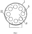
- a coal decomposition equipment comprises an airtight kiln body 1 with coal inlet 2 and coal outlet 3.
- the kiln body 1 is a horizontal and rotary kiln.
- a flame gas pipeline heating facility is set in the kiln body 1 and a channel 4 for impelling and decomposing coal is formed between the flame gas pipeline heating facility and an inner wall of the kiln body.
- a coal decomposition gas collecting pipe 5 is provided on the kiln body 1 to communicate with the channel 4, and an impelling board 10 is set in the inner wall of the kiln body 1.
- the flame gas pipeline heating facility includes a flame gas heat dissipation pipe 6 and a combustor chamber 7.
- the combustor chamber 7 communicates with a fuel supply pipe 8 and an air supply pipe 9 which are both set outside of the kiln body 1.
- the fuel in the fuel supply pipe 8 and the air in the air supply pipe 9 are mixed combustion in the combustor chamber 7, and the produced the high temperature flame gas come into the flame gas heat dissipation pipe 6, then the flame gas heat dissipation pipe 6 transfers the heat to the pulverized coal in the channel 4.
- the pulverized coal fully absorbs the heat so as to be heated and decomposed to the gas, coal tar gas and coal with a higher heat-value in the channel 4.
- the gas and coal tar gas communicate with a gas dedust and liquefaction facility outside of the kiln body 1 through the coal decomposition gas collecting pipe 5, and the decomposed gas and coal tar gas are collected, dedusted, separated, and pressure liquefied by the gas dedust and liquefaction facility.
- the coals with higher heat-value are collected through the coal outlet 3.
- a coal decomposition equipment comprises an airtight kiln body 1 with an inlet 2 and an outlet 3.
- the kiln body 1 is a horizontal and rotary kiln.
- a flame gas pipeline heating facility is set in the kiln body 1 and a channel 4 for impelling and decomposing coal is formed between the flame gas pipeline heating facility and an inner wall of the kiln body.
- a coal decomposition gas collecting pipe 5 is provided on the kiln body 1 to communicate with the channel 4, and an impelling board 10 is set in the inner wall of the kiln body 1.
- the flame gas pipeline heating facility includes a flame gas heat dissipation pipe 6 and a combustor chamber 7.
- the flame gas heat dissipation pipe 6 and the combustor chamber 7 communicate with a fuel supply pipe 8 and an air supply pipe 9.
- the flame gas heat dissipation pipe consists of multiple parallel close-packed pipes or tube mesh close-packed pipes so that the produced heat will be sufficiently transferred to the pulverized coal.
- the fuel in the fuel supply pipe 8 and the air in the air supply pipe 9 are mixed combustion in the combustor chamber 7, and the produced the high temperature flame gas come into the flame gas heat dissipation pipe 6, then the flame gas heat dissipation pipe 6 transfers the heat to the pulverized coal in the channel 4.
- the pulverized coal fully absorbs the heat so as to be heated and decomposed to the gas, coal tar gas and coal with a higher heat-value in the channel 4.
- the gas and coal tar gas communicate with a gas dedust and liquefaction facility outside of the kiln body 1 through the coal decomposition gas collecting pipe 5, and the decomposed gas and coal tar gas are collected, dedusted, separated, and pressure liquefied by the gas dedust and liquefaction facility.
- the coals with higher heat-value are collected through the coal outlet 3.
- a coal decomposition equipment comprises an airtight kiln body 1 with an inlet 2 and an outlet 3.
- the kiln body 1 is an up-draft and rotary kiln.
- a flame gas pipeline heating facility is set in the kiln body 1 and a channel 4 for impelling and decomposing coal is formed between the flame gas pipeline heating facility and an inner wall of the kiln body.
- a coal decomposition gas collecting pipe 5 is provided on the kiln body 1 to communicate with the channel 4, and an impelling board 10 is set in the inner wall of the kiln body 1.
- the flame gas pipeline heating facility includes a flame gas heat dissipation pipe 6.
- the flame gas heat dissipation pipe 6 communicates with a combustor chamber 7, a fuel supply pipe 8 and an air supply pipe 9, which are all set outside of the kiln body 1.
- the flame gas heat dissipation pipe consists of multiple parallel close-packed pipes or tube mesh close-packed pipes so that the produced heat will be sufficiently transferred to the pulverized coal.
- the fuel in the fuel supply pipe 8 and the air in the air supply pipe 9 are mixed combustion in the combustor chamber 7, and the produced the high temperature flame gas come into the flame gas heat dissipation pipe 6, then the flame gas heat dissipation pipe 6 transfers the heat to the pulverized coal in the channel 4.
- the pulverized coal fully absorbs the heat so as to be heated and decomposed to the gas, coal tar gas and coal with a higher heat-value in the channel 4.
- the gas and coal tar gas communicate with a gas dedust and liquefaction facility outside of the kiln body 1 through the coal decomposition gas collecting pipe 5, and the decomposed gas and coal tar gas are collected, dedusted, separated, and pressure liquefied by the gas dedust and liquefaction facility.
Landscapes
- Chemical & Material Sciences (AREA)
- Engineering & Computer Science (AREA)
- Oil, Petroleum & Natural Gas (AREA)
- Organic Chemistry (AREA)
- Combustion & Propulsion (AREA)
- Materials Engineering (AREA)
- Chemical Kinetics & Catalysis (AREA)
- General Chemical & Material Sciences (AREA)
- Production Of Liquid Hydrocarbon Mixture For Refining Petroleum (AREA)
- Muffle Furnaces And Rotary Kilns (AREA)
- Solid Fuels And Fuel-Associated Substances (AREA)
- Industrial Gases (AREA)
- Carbon And Carbon Compounds (AREA)
Claims (1)
- Équipement de décomposition de gaz pulvérisé comprenant :un corps de four étanche à l'air (1) avec une entrée (2) et une sortie (3) dans lequel une installation de chauffage à tuyauterie de gaz de flamme est installée dans le corps de four (1) et un canal (4) pour forcer et décomposer le charbon pulvérisé est formé entre l'installation de chauffage à tuyauterie de gaz de flamme et une paroi interne du corps de four (1) ; et un tuyau de collecte de gaz de décomposition de charbon pulvérisé (5) est fourni sur le corps de four (1) pour communiquer avec le canal (4) ; le corps de four (1) est un four horizontal et rotatif et un montage de forçage (10) est installé dans la paroi interne du corps de four (1) ; caractérisé en ce que l'installation de chauffage à tuyauterie de gaz de flamme comprend un tuyau d'apport de carburant (8), un tuyau d'apport d'air (9), une chambre de combustion (7) et un tuyau de dissipation de chaleur de gaz de flamme (6), le tuyau de dissipation de chaleur de gaz de flamme (6) est constitué de tuyaux étroitement compactés se formant en tube.
Applications Claiming Priority (2)
| Application Number | Priority Date | Filing Date | Title |
|---|---|---|---|
| CN2010102627866A CN101985558B (zh) | 2010-08-19 | 2010-08-19 | 煤物质的分解设备 |
| PCT/CN2010/077020 WO2012022059A1 (fr) | 2010-08-19 | 2010-09-17 | Appareil destiné à la pyrolyse d'une substance charbonneuse |
Publications (3)
| Publication Number | Publication Date |
|---|---|
| EP2610324A1 EP2610324A1 (fr) | 2013-07-03 |
| EP2610324A4 EP2610324A4 (fr) | 2014-10-22 |
| EP2610324B1 true EP2610324B1 (fr) | 2017-04-19 |
Family
ID=43709960
Family Applications (1)
| Application Number | Title | Priority Date | Filing Date |
|---|---|---|---|
| EP10856057.4A Active EP2610324B1 (fr) | 2010-08-19 | 2010-09-17 | Appareil destiné à la pyrolyse d'une substance charbonneuse |
Country Status (18)
| Country | Link |
|---|---|
| US (1) | US20120308951A1 (fr) |
| EP (1) | EP2610324B1 (fr) |
| JP (1) | JP5756814B2 (fr) |
| KR (1) | KR101584122B1 (fr) |
| CN (1) | CN101985558B (fr) |
| AU (1) | AU2010359254B2 (fr) |
| BR (1) | BR112012019128B1 (fr) |
| CA (1) | CA2787465C (fr) |
| CL (1) | CL2012002353A1 (fr) |
| CO (1) | CO6670541A2 (fr) |
| EA (1) | EA028446B1 (fr) |
| MX (1) | MX349063B (fr) |
| NZ (1) | NZ601451A (fr) |
| PL (1) | PL2610324T3 (fr) |
| PT (1) | PT2610324T (fr) |
| UA (1) | UA105683C2 (fr) |
| WO (1) | WO2012022059A1 (fr) |
| ZA (1) | ZA201205286B (fr) |
Families Citing this family (15)
| Publication number | Priority date | Publication date | Assignee | Title |
|---|---|---|---|---|
| CN101984022B (zh) * | 2010-10-26 | 2011-08-10 | 西峡龙成特种材料有限公司 | 多管外热式煤粉分解设备 |
| CN102295939A (zh) * | 2011-08-04 | 2011-12-28 | 西峡龙成特种材料有限公司 | 碎煤、粉煤的分解设备 |
| CN102492445A (zh) * | 2011-11-17 | 2012-06-13 | 山东天力干燥股份有限公司 | 一种粉煤的多管回转低温干馏工艺方法 |
| CN102786234B (zh) * | 2012-07-04 | 2014-04-23 | 赵光辉 | 能回收co2的u形内燃旋转石灰窑 |
| CN103265965A (zh) * | 2013-04-24 | 2013-08-28 | 河南龙成煤高效技术应用有限公司 | 高效能煤分解设备 |
| DE102013009961A1 (de) * | 2013-05-17 | 2014-12-04 | BLüCHER GMBH | Drehrohr und Drehrohrofen zur Herstel1ung von Aktivkohle |
| CN104531171B (zh) * | 2014-12-30 | 2018-11-23 | 贺守印 | 一种高效节能环保炭化炉 |
| CN104789241B (zh) * | 2015-03-31 | 2017-10-31 | 长安大学 | 一种粉煤热解回转炉 |
| CN106281382A (zh) * | 2016-09-12 | 2017-01-04 | 新疆广汇中化能源技术开发有限公司 | 转式辐射床 |
| CN106833700B (zh) * | 2017-02-24 | 2022-03-22 | 中冶焦耐(大连)工程技术有限公司 | 一种外热式低阶粉煤连续干馏炉的炭化室炉顶装煤箱 |
| CN107033963A (zh) * | 2017-05-31 | 2017-08-11 | 河南龙成煤高效技术应用有限公司 | 一种煤热解工艺装置 |
| CN107760346A (zh) * | 2017-11-24 | 2018-03-06 | 北京神雾电力科技有限公司 | 一种多段式快速热解反应系统及方法 |
| CN107892934A (zh) * | 2017-12-12 | 2018-04-10 | 长春三真实业有限公司 | 一种油砂分离热解装置 |
| CN110160037A (zh) * | 2017-12-25 | 2019-08-23 | 姚士茜 | 一种炉箅子旋转的横置式节能锅炉 |
| CN112708430B (zh) * | 2021-01-04 | 2022-03-04 | 山东省科学院能源研究所 | 一种连续式固体有机物热解多联产系统及其使用方法 |
Family Cites Families (82)
| Publication number | Priority date | Publication date | Assignee | Title |
|---|---|---|---|---|
| US1587256A (en) * | 1924-04-09 | 1926-06-01 | Foulk | Rotary oil-shale retort |
| US1993934A (en) * | 1930-09-04 | 1935-03-12 | Zareh H Kevorkian | Apparatus for production of coke and recovery of by-products therefrom |
| US1893857A (en) * | 1930-12-18 | 1933-01-10 | Charles M Buck | Pulverized fuel feeder |
| US1925132A (en) * | 1932-08-16 | 1933-09-05 | Charles M Buck | Combustion of coal |
| US2074881A (en) * | 1934-09-21 | 1937-03-23 | Witting Albin Gottlieb | Apparatus for preheating coal before coking |
| US2151849A (en) * | 1936-03-20 | 1939-03-28 | British Coal Distillation Ltd | Distillation of solid carbonaceous materials and apparatus therefor |
| US2436487A (en) * | 1943-12-11 | 1948-02-24 | Babcock & Wilcox Co | Closed-loop material transport system, including an in-circuit pulverizer |
| US2559557A (en) * | 1944-07-12 | 1951-07-03 | Babcock & Wilcox Co | Aerating feeding of pulverized materials |
| US2865820A (en) * | 1951-04-18 | 1958-12-23 | Koppers Co Inc | Method for heat treatment of finely divided solid media |
| US2777407A (en) * | 1951-10-02 | 1957-01-15 | Babcock & Wilcox Co | Fuel burning apparatus |
| US2755750A (en) * | 1952-01-04 | 1956-07-24 | Australian Iron & Steel Ltd | Fluid mixing apparatus |
| US2754981A (en) * | 1953-03-12 | 1956-07-17 | Koppers Co Inc | Side charged horizontal coke oven battery and method |
| US3058229A (en) * | 1960-03-22 | 1962-10-16 | Downing Richard | Method and apparatus for drying coal |
| US3387380A (en) * | 1961-05-05 | 1968-06-11 | Willis L. Pritts Jr. | Coal drying apparatus |
| US3178235A (en) * | 1963-03-29 | 1965-04-13 | Koppers Co Inc | Rotary feeder |
| JPS4529726B1 (fr) * | 1965-12-22 | 1970-09-28 | ||
| US3481720A (en) * | 1966-04-29 | 1969-12-02 | Sun Oil Co | Process and apparatus for the distillation of solids |
| US3397256A (en) * | 1966-07-01 | 1968-08-13 | Baker Co J E | Combustion process and apparatus to increase a flame temperature |
| US4285773A (en) * | 1977-08-27 | 1981-08-25 | Alberta Oil Sands Technology And Research Authority | Apparatus and process for recovery of hydrocarbon from inorganic host materials |
| US4123332A (en) * | 1977-09-06 | 1978-10-31 | Energy Recovery Research Group, Inc. | Process and apparatus for carbonizing a comminuted solid carbonizable material |
| US4257761A (en) * | 1979-03-19 | 1981-03-24 | Combustion Engineering, Inc. | Multiple jet coal burner |
| JPS6014064B2 (ja) * | 1979-09-28 | 1985-04-11 | 日立造船株式会社 | 炭製造方法 |
| DE2944693A1 (de) * | 1979-11-06 | 1981-05-14 | Hölter, Ing.(grad.), Heinz, 4390 Gladbeck | Muellpyrolyse-drehrohofen |
| US4373900A (en) * | 1979-11-23 | 1983-02-15 | Pillard, Inc. | Burner for a kiln |
| US4321034A (en) * | 1980-04-03 | 1982-03-23 | Clearfield Machine Company | Coal burners, rotary furnaces incorporating the same and methods of operating |
| US4348170A (en) * | 1980-06-04 | 1982-09-07 | Foster Wheeler Energy Corporation | Dual register, split stream burner assembly with divider cone |
| US4326700A (en) * | 1980-07-30 | 1982-04-27 | Southware Company | Dual fuel burner for metal melting furnaces |
| US4378243A (en) * | 1981-05-22 | 1983-03-29 | The Direct Reduction Corporation | System for coal blowing in iron oxide reducing kilns |
| US4421039A (en) * | 1981-09-24 | 1983-12-20 | Combustion Engineering, Inc. | Pulverized coal-fired burner |
| US4473441A (en) * | 1983-03-09 | 1984-09-25 | Carbon Dynamics, Inc. | Apparatus for heat induced separation of hydrocarbon constituents from coal |
| US4924784A (en) * | 1984-02-27 | 1990-05-15 | International Coal Refining Company | Firing of pulverized solvent refined coal |
| US5011400A (en) * | 1986-02-03 | 1991-04-30 | Foster Wheeler Energy Corporation | Controlled flow split steam burner assembly with sorbent injection |
| EP0248539B1 (fr) * | 1986-05-07 | 1992-01-29 | Hitachi, Ltd. | Atomiseur et chaudière à boue de charbon et d'eau comportant un tel atomiseur |
| US4920925A (en) * | 1986-11-07 | 1990-05-01 | Donlee Technologies Inc. | Boiler with cyclonic combustion |
| US4902221A (en) * | 1987-05-12 | 1990-02-20 | Control Systems Company | Burner assembly for coal fired furnaces |
| US5078836A (en) * | 1989-07-21 | 1992-01-07 | Hogan Jim S | Method and apparatus for retorting material |
| US5225044A (en) * | 1990-03-14 | 1993-07-06 | Wayne Technology, Inc. | Pyrolytic conversion system |
| US5082534A (en) * | 1990-03-14 | 1992-01-21 | Wayne Technology, Inc. | Pyrolytic conversion system |
| DK169446B1 (da) * | 1991-04-19 | 1994-10-31 | Smidth & Co As F L | Brænder til roterovn samt fremgangsmåde til dannelse af en brænderflamme med brænderen |
| JPH0510989U (ja) * | 1991-07-24 | 1993-02-12 | 川崎製鉄株式会社 | 粉粒体の間接加熱管式回転乾燥機 |
| US5254139A (en) * | 1991-08-05 | 1993-10-19 | Adams Robert J | Method for treating coal |
| CA2086399C (fr) * | 1992-01-27 | 2004-03-30 | Joel Vatsky | Ensemble bruleur a flux d'alimentation divergent |
| DE4326679A1 (de) * | 1993-08-09 | 1995-02-16 | Siemens Ag | Heizkammer für Festgut |
| DE4329871A1 (de) * | 1993-09-03 | 1995-03-09 | Siemens Ag | Innenberohrte, drehbare Heizkammer für Abfall |
| SK281940B6 (sk) * | 1993-09-03 | 2001-09-11 | Siemens Aktiengesellschaft | Otočná vykurovacia komora na pevný materiál |
| CA2151308C (fr) * | 1994-06-17 | 1999-06-08 | Hideaki Ohta | Bruleur a combustible pulverise |
| US5906483A (en) * | 1998-05-01 | 1999-05-25 | Harper International Corp. | Rotary film calciner |
| US6042365A (en) * | 1999-06-28 | 2000-03-28 | Chen; Yaosheng | Fuel combustion monitoring apparatus and method |
| US6347937B1 (en) * | 2000-01-21 | 2002-02-19 | Ats Spartec Inc. | Rotary kiln burner |
| US6475267B2 (en) * | 2000-12-13 | 2002-11-05 | Foster Wheeler Energy Corporation | System and method for removing gas from a stream of a mixture of gas and particulate solids |
| JP2002212568A (ja) * | 2001-01-18 | 2002-07-31 | Kyocera Corp | 間接加熱式回転乾燥機 |
| CN2498158Y (zh) * | 2001-08-29 | 2002-07-03 | 东南大学 | 由生物质制取中热值煤气的热解炉 |
| CA2625463C (fr) * | 2001-11-16 | 2011-03-08 | Hitachi, Ltd. | Bruleur pour carburant solide, methode de combustion avec ce bruleur, appareil a combustion et methode pour faire fonctionner cet appareil |
| JP3525385B2 (ja) * | 2002-01-08 | 2004-05-10 | 優之 松井 | 炭化炉 |
| US20060169181A1 (en) * | 2003-02-24 | 2006-08-03 | Posco | Method and burner apparatus for injecting a pulverized coal into rotary kilns, method and apparatus for producing cao using them |
| CN2658150Y (zh) * | 2003-10-22 | 2004-11-24 | 李志远 | 组合式型焦炉 |
| US7028478B2 (en) * | 2003-12-16 | 2006-04-18 | Advanced Combustion Energy Systems, Inc. | Method and apparatus for the production of energy |
| US20060246388A1 (en) * | 2005-04-29 | 2006-11-02 | Hauck Manufacturing Company | Reduced NOx method of combustion |
| JP4910431B2 (ja) * | 2006-03-10 | 2012-04-04 | 株式会社Ihi | 廃棄物の熱分解ガス化方法及び装置 |
| KR100753425B1 (ko) * | 2006-09-15 | 2007-08-31 | (주) 세영산업 | 폐목재를 이용한 활성탄제조장치 |
| US9045693B2 (en) * | 2006-12-26 | 2015-06-02 | Nucor Corporation | Pyrolyzer furnace apparatus and method for operation thereof |
| US8444828B2 (en) * | 2006-12-26 | 2013-05-21 | Nucor Corporation | Pyrolyzer furnace apparatus and method for operation thereof |
| WO2009032793A1 (fr) * | 2007-09-06 | 2009-03-12 | Coen Company, Inc. | Pilote de brûleur avec rotor virtuel |
| JP4979538B2 (ja) * | 2007-10-16 | 2012-07-18 | 株式会社神戸製鋼所 | 間接加熱乾燥装置、被乾燥物の間接加熱乾燥方法、ならびに固形燃料の製造方法および製造装置 |
| US8168043B2 (en) * | 2008-08-29 | 2012-05-01 | Eau-Viron Incorporated | Retort apparatus and method for continuously processing liquid and solid mixtures and for recovering products therefrom |
| CN201306834Y (zh) * | 2008-09-11 | 2009-09-09 | 刘伟义 | 卧式燃煤气化环保锅炉 |
| CN101368728B (zh) * | 2008-09-11 | 2011-06-08 | 上海工程技术大学 | 煤粉燃烧方法与煤粉燃烧器 |
| BRPI0804349A2 (pt) * | 2008-10-16 | 2010-07-13 | Rm Materiais Refratarios Ltda | aparelho e processo para decomposição térmica de qualquer tipo de material orgánico |
| IT1394846B1 (it) * | 2009-07-17 | 2012-07-20 | Eni Spa | Procedimento ed apparecchiatura per il trattamento termico di fanghi di raffineria |
| JP4896195B2 (ja) * | 2009-09-30 | 2012-03-14 | 株式会社日立製作所 | 酸素燃焼ボイラプラント及び酸素燃焼ボイラプラントの運転方法 |
| CN101693848B (zh) * | 2009-10-19 | 2013-01-02 | 中国林业科学研究院林产化学工业研究所 | 内热式连续制备生物质热解气化煤气的方法及用的回转炉 |
| CN102753655B (zh) * | 2010-01-04 | 2017-03-29 | 鲁道夫·安东尼奥·M·戈麦斯 | 用于发电站的先进的煤升级方法 |
| CN101985559B (zh) * | 2010-08-19 | 2011-08-17 | 西峡龙成特种材料有限公司 | 电热式粉煤分解设备 |
| CN201729797U (zh) * | 2010-08-19 | 2011-02-02 | 西峡龙成特种材料有限公司 | 煤物质的分解设备 |
| CN201729800U (zh) * | 2010-08-19 | 2011-02-02 | 西峡龙成特种材料有限公司 | 煤物质的伞状支撑立式分解设备 |
| CN201729799U (zh) * | 2010-08-19 | 2011-02-02 | 西峡龙成特种材料有限公司 | 煤物质横插燃气管立式分解设备 |
| CN101985562B (zh) * | 2010-08-19 | 2011-09-14 | 西峡龙成特种材料有限公司 | 煤物质多燃烧器卧式分离设备 |
| CN201729801U (zh) * | 2010-08-19 | 2011-02-02 | 西峡龙成特种材料有限公司 | 煤物质的立式分解设备 |
| CN101985564B (zh) * | 2010-08-19 | 2011-09-14 | 西峡龙成特种材料有限公司 | 煤物质的立式分解设备 |
| CN101984022B (zh) * | 2010-10-26 | 2011-08-10 | 西峡龙成特种材料有限公司 | 多管外热式煤粉分解设备 |
| CN101984021B (zh) * | 2010-10-26 | 2011-08-10 | 西峡龙成特种材料有限公司 | 加热气循环式粉煤分解设备 |
| CN102260559B (zh) * | 2011-05-31 | 2014-06-18 | 千秋能源(上海)有限公司 | 优质煤产品生产装置及生产系统 |
-
2010
- 2010-08-19 CN CN2010102627866A patent/CN101985558B/zh not_active Ceased
- 2010-09-17 CA CA2787465A patent/CA2787465C/fr active Active
- 2010-09-17 EA EA201270667A patent/EA028446B1/ru not_active IP Right Cessation
- 2010-09-17 PT PT108560574T patent/PT2610324T/pt unknown
- 2010-09-17 EP EP10856057.4A patent/EP2610324B1/fr active Active
- 2010-09-17 US US13/578,630 patent/US20120308951A1/en not_active Abandoned
- 2010-09-17 JP JP2012549232A patent/JP5756814B2/ja active Active
- 2010-09-17 MX MX2012008726A patent/MX349063B/es active IP Right Grant
- 2010-09-17 NZ NZ601451A patent/NZ601451A/en unknown
- 2010-09-17 PL PL10856057T patent/PL2610324T3/pl unknown
- 2010-09-17 WO PCT/CN2010/077020 patent/WO2012022059A1/fr active Application Filing
- 2010-09-17 BR BR112012019128-4A patent/BR112012019128B1/pt active IP Right Grant
- 2010-09-17 UA UAA201208963A patent/UA105683C2/uk unknown
- 2010-09-17 KR KR1020127019726A patent/KR101584122B1/ko active IP Right Grant
- 2010-09-17 AU AU2010359254A patent/AU2010359254B2/en active Active
-
2012
- 2012-07-17 ZA ZA2012/05286A patent/ZA201205286B/en unknown
- 2012-08-24 CL CL2012002353A patent/CL2012002353A1/es unknown
-
2013
- 2013-01-31 CO CO13018585A patent/CO6670541A2/es active IP Right Grant
Non-Patent Citations (1)
| Title |
|---|
| None * |
Also Published As
| Publication number | Publication date |
|---|---|
| AU2010359254B2 (en) | 2013-05-16 |
| KR20120124425A (ko) | 2012-11-13 |
| AU2010359254A1 (en) | 2012-08-09 |
| CO6670541A2 (es) | 2013-05-15 |
| KR101584122B1 (ko) | 2016-01-12 |
| CN101985558A (zh) | 2011-03-16 |
| EA028446B1 (ru) | 2017-11-30 |
| CA2787465A1 (fr) | 2012-02-23 |
| UA105683C2 (uk) | 2014-06-10 |
| NZ601451A (en) | 2014-09-26 |
| CA2787465C (fr) | 2016-10-11 |
| PT2610324T (pt) | 2017-07-12 |
| CN101985558B (zh) | 2012-01-04 |
| EP2610324A4 (fr) | 2014-10-22 |
| ZA201205286B (en) | 2013-06-26 |
| BR112012019128A2 (pt) | 2018-05-29 |
| JP2013518134A (ja) | 2013-05-20 |
| JP5756814B2 (ja) | 2015-07-29 |
| EP2610324A1 (fr) | 2013-07-03 |
| PL2610324T3 (pl) | 2017-09-29 |
| US20120308951A1 (en) | 2012-12-06 |
| MX349063B (es) | 2017-07-07 |
| WO2012022059A1 (fr) | 2012-02-23 |
| EA201270667A1 (ru) | 2013-05-30 |
| CL2012002353A1 (es) | 2013-07-19 |
| BR112012019128B1 (pt) | 2019-03-19 |
| MX2012008726A (es) | 2012-11-29 |
Similar Documents
| Publication | Publication Date | Title |
|---|---|---|
| EP2610324B1 (fr) | Appareil destiné à la pyrolyse d'une substance charbonneuse | |
| EP2607453B1 (fr) | Appareil de pyrolyse vertical pour substance charbonneuse | |
| AU2010359252B2 (en) | Electrical-heating coal material decomposition device | |
| CN101985562B (zh) | 煤物质多燃烧器卧式分离设备 | |
| CN201729799U (zh) | 煤物质横插燃气管立式分解设备 | |
| CN201770660U (zh) | 煤物质横插管立式分解设备 | |
| CN201729800U (zh) | 煤物质的伞状支撑立式分解设备 | |
| CN201729797U (zh) | 煤物质的分解设备 | |
| CN101985561B (zh) | 煤物质的伞状支撑立式分解设备 | |
| CN101985565B (zh) | 煤物质多燃烧器子母管分离设备 | |
| CN101985560B (zh) | 煤物质横插燃气管立式分解设备 | |
| CN101985563B (zh) | 煤物质横插管立式分解设备 |
Legal Events
| Date | Code | Title | Description |
|---|---|---|---|
| PUAI | Public reference made under article 153(3) epc to a published international application that has entered the european phase |
Free format text: ORIGINAL CODE: 0009012 |
|
| 17P | Request for examination filed |
Effective date: 20120724 |
|
| AK | Designated contracting states |
Kind code of ref document: A1 Designated state(s): AL AT BE BG CH CY CZ DE DK EE ES FI FR GB GR HR HU IE IS IT LI LT LU LV MC MK MT NL NO PL PT RO SE SI SK SM TR |
|
| DAX | Request for extension of the european patent (deleted) | ||
| A4 | Supplementary search report drawn up and despatched |
Effective date: 20140924 |
|
| RIC1 | Information provided on ipc code assigned before grant |
Ipc: C10B 57/08 20060101ALI20140918BHEP Ipc: C10B 23/00 20060101ALI20140918BHEP Ipc: C10B 7/00 20060101ALI20140918BHEP Ipc: C10B 53/04 20060101AFI20140918BHEP |
|
| 17Q | First examination report despatched |
Effective date: 20150710 |
|
| GRAP | Despatch of communication of intention to grant a patent |
Free format text: ORIGINAL CODE: EPIDOSNIGR1 |
|
| INTG | Intention to grant announced |
Effective date: 20161114 |
|
| GRAS | Grant fee paid |
Free format text: ORIGINAL CODE: EPIDOSNIGR3 |
|
| GRAA | (expected) grant |
Free format text: ORIGINAL CODE: 0009210 |
|
| AK | Designated contracting states |
Kind code of ref document: B1 Designated state(s): AL AT BE BG CH CY CZ DE DK EE ES FI FR GB GR HR HU IE IS IT LI LT LU LV MC MK MT NL NO PL PT RO SE SI SK SM TR |
|
| REG | Reference to a national code |
Ref country code: GB Ref legal event code: FG4D |
|
| REG | Reference to a national code |
Ref country code: RO Ref legal event code: EPE |
|
| REG | Reference to a national code |
Ref country code: CH Ref legal event code: EP |
|
| REG | Reference to a national code |
Ref country code: NL Ref legal event code: FP |
|
| REG | Reference to a national code |
Ref country code: AT Ref legal event code: REF Ref document number: 885961 Country of ref document: AT Kind code of ref document: T Effective date: 20170515 |
|
| REG | Reference to a national code |
Ref country code: IE Ref legal event code: FG4D |
|
| REG | Reference to a national code |
Ref country code: DE Ref legal event code: R096 Ref document number: 602010041760 Country of ref document: DE |
|
| REG | Reference to a national code |
Ref country code: PT Ref legal event code: SC4A Ref document number: 2610324 Country of ref document: PT Date of ref document: 20170712 Kind code of ref document: T Free format text: AVAILABILITY OF NATIONAL TRANSLATION Effective date: 20170630 |
|
| REG | Reference to a national code |
Ref country code: LT Ref legal event code: MG4D |
|
| REG | Reference to a national code |
Ref country code: AT Ref legal event code: MK05 Ref document number: 885961 Country of ref document: AT Kind code of ref document: T Effective date: 20170419 |
|
| REG | Reference to a national code |
Ref country code: FR Ref legal event code: PLFP Year of fee payment: 8 |
|
| PG25 | Lapsed in a contracting state [announced via postgrant information from national office to epo] |
Ref country code: NO Free format text: LAPSE BECAUSE OF FAILURE TO SUBMIT A TRANSLATION OF THE DESCRIPTION OR TO PAY THE FEE WITHIN THE PRESCRIBED TIME-LIMIT Effective date: 20170719 Ref country code: FI Free format text: LAPSE BECAUSE OF FAILURE TO SUBMIT A TRANSLATION OF THE DESCRIPTION OR TO PAY THE FEE WITHIN THE PRESCRIBED TIME-LIMIT Effective date: 20170419 Ref country code: LT Free format text: LAPSE BECAUSE OF FAILURE TO SUBMIT A TRANSLATION OF THE DESCRIPTION OR TO PAY THE FEE WITHIN THE PRESCRIBED TIME-LIMIT Effective date: 20170419 Ref country code: AT Free format text: LAPSE BECAUSE OF FAILURE TO SUBMIT A TRANSLATION OF THE DESCRIPTION OR TO PAY THE FEE WITHIN THE PRESCRIBED TIME-LIMIT Effective date: 20170419 Ref country code: ES Free format text: LAPSE BECAUSE OF FAILURE TO SUBMIT A TRANSLATION OF THE DESCRIPTION OR TO PAY THE FEE WITHIN THE PRESCRIBED TIME-LIMIT Effective date: 20170419 Ref country code: HR Free format text: LAPSE BECAUSE OF FAILURE TO SUBMIT A TRANSLATION OF THE DESCRIPTION OR TO PAY THE FEE WITHIN THE PRESCRIBED TIME-LIMIT Effective date: 20170419 |
|
| REG | Reference to a national code |
Ref country code: GR Ref legal event code: EP Ref document number: 20170401477 Country of ref document: GR Effective date: 20171023 |
|
| PG25 | Lapsed in a contracting state [announced via postgrant information from national office to epo] |
Ref country code: SE Free format text: LAPSE BECAUSE OF FAILURE TO SUBMIT A TRANSLATION OF THE DESCRIPTION OR TO PAY THE FEE WITHIN THE PRESCRIBED TIME-LIMIT Effective date: 20170419 Ref country code: IS Free format text: LAPSE BECAUSE OF FAILURE TO SUBMIT A TRANSLATION OF THE DESCRIPTION OR TO PAY THE FEE WITHIN THE PRESCRIBED TIME-LIMIT Effective date: 20170819 Ref country code: LV Free format text: LAPSE BECAUSE OF FAILURE TO SUBMIT A TRANSLATION OF THE DESCRIPTION OR TO PAY THE FEE WITHIN THE PRESCRIBED TIME-LIMIT Effective date: 20170419 |
|
| REG | Reference to a national code |
Ref country code: DE Ref legal event code: R097 Ref document number: 602010041760 Country of ref document: DE |
|
| PG25 | Lapsed in a contracting state [announced via postgrant information from national office to epo] |
Ref country code: EE Free format text: LAPSE BECAUSE OF FAILURE TO SUBMIT A TRANSLATION OF THE DESCRIPTION OR TO PAY THE FEE WITHIN THE PRESCRIBED TIME-LIMIT Effective date: 20170419 Ref country code: SK Free format text: LAPSE BECAUSE OF FAILURE TO SUBMIT A TRANSLATION OF THE DESCRIPTION OR TO PAY THE FEE WITHIN THE PRESCRIBED TIME-LIMIT Effective date: 20170419 Ref country code: DK Free format text: LAPSE BECAUSE OF FAILURE TO SUBMIT A TRANSLATION OF THE DESCRIPTION OR TO PAY THE FEE WITHIN THE PRESCRIBED TIME-LIMIT Effective date: 20170419 |
|
| PLBE | No opposition filed within time limit |
Free format text: ORIGINAL CODE: 0009261 |
|
| STAA | Information on the status of an ep patent application or granted ep patent |
Free format text: STATUS: NO OPPOSITION FILED WITHIN TIME LIMIT |
|
| PG25 | Lapsed in a contracting state [announced via postgrant information from national office to epo] |
Ref country code: SM Free format text: LAPSE BECAUSE OF FAILURE TO SUBMIT A TRANSLATION OF THE DESCRIPTION OR TO PAY THE FEE WITHIN THE PRESCRIBED TIME-LIMIT Effective date: 20170419 |
|
| 26N | No opposition filed |
Effective date: 20180122 |
|
| REG | Reference to a national code |
Ref country code: CH Ref legal event code: PL |
|
| PG25 | Lapsed in a contracting state [announced via postgrant information from national office to epo] |
Ref country code: SI Free format text: LAPSE BECAUSE OF FAILURE TO SUBMIT A TRANSLATION OF THE DESCRIPTION OR TO PAY THE FEE WITHIN THE PRESCRIBED TIME-LIMIT Effective date: 20170419 Ref country code: MC Free format text: LAPSE BECAUSE OF FAILURE TO SUBMIT A TRANSLATION OF THE DESCRIPTION OR TO PAY THE FEE WITHIN THE PRESCRIBED TIME-LIMIT Effective date: 20170419 |
|
| REG | Reference to a national code |
Ref country code: IE Ref legal event code: MM4A |
|
| REG | Reference to a national code |
Ref country code: BE Ref legal event code: MM Effective date: 20170930 |
|
| PG25 | Lapsed in a contracting state [announced via postgrant information from national office to epo] |
Ref country code: LU Free format text: LAPSE BECAUSE OF NON-PAYMENT OF DUE FEES Effective date: 20170917 |
|
| PG25 | Lapsed in a contracting state [announced via postgrant information from national office to epo] |
Ref country code: LI Free format text: LAPSE BECAUSE OF NON-PAYMENT OF DUE FEES Effective date: 20170930 Ref country code: IE Free format text: LAPSE BECAUSE OF NON-PAYMENT OF DUE FEES Effective date: 20170917 Ref country code: CH Free format text: LAPSE BECAUSE OF NON-PAYMENT OF DUE FEES Effective date: 20170930 |
|
| PG25 | Lapsed in a contracting state [announced via postgrant information from national office to epo] |
Ref country code: BE Free format text: LAPSE BECAUSE OF NON-PAYMENT OF DUE FEES Effective date: 20170930 |
|
| PG25 | Lapsed in a contracting state [announced via postgrant information from national office to epo] |
Ref country code: MT Free format text: LAPSE BECAUSE OF NON-PAYMENT OF DUE FEES Effective date: 20170917 |
|
| REG | Reference to a national code |
Ref country code: FR Ref legal event code: PLFP Year of fee payment: 9 |
|
| PG25 | Lapsed in a contracting state [announced via postgrant information from national office to epo] |
Ref country code: HU Free format text: LAPSE BECAUSE OF FAILURE TO SUBMIT A TRANSLATION OF THE DESCRIPTION OR TO PAY THE FEE WITHIN THE PRESCRIBED TIME-LIMIT; INVALID AB INITIO Effective date: 20100917 |
|
| PGFP | Annual fee paid to national office [announced via postgrant information from national office to epo] |
Ref country code: NL Payment date: 20190830 Year of fee payment: 10 |
|
| PG25 | Lapsed in a contracting state [announced via postgrant information from national office to epo] |
Ref country code: CY Free format text: LAPSE BECAUSE OF NON-PAYMENT OF DUE FEES Effective date: 20170419 |
|
| PGFP | Annual fee paid to national office [announced via postgrant information from national office to epo] |
Ref country code: PT Payment date: 20190906 Year of fee payment: 10 Ref country code: RO Payment date: 20190912 Year of fee payment: 10 Ref country code: TR Payment date: 20190913 Year of fee payment: 10 Ref country code: FR Payment date: 20190829 Year of fee payment: 10 Ref country code: CZ Payment date: 20190910 Year of fee payment: 10 Ref country code: IT Payment date: 20190920 Year of fee payment: 10 Ref country code: DE Payment date: 20190829 Year of fee payment: 10 |
|
| PG25 | Lapsed in a contracting state [announced via postgrant information from national office to epo] |
Ref country code: MK Free format text: LAPSE BECAUSE OF FAILURE TO SUBMIT A TRANSLATION OF THE DESCRIPTION OR TO PAY THE FEE WITHIN THE PRESCRIBED TIME-LIMIT Effective date: 20170419 |
|
| PGFP | Annual fee paid to national office [announced via postgrant information from national office to epo] |
Ref country code: BG Payment date: 20190920 Year of fee payment: 10 Ref country code: GR Payment date: 20190919 Year of fee payment: 10 |
|
| PG25 | Lapsed in a contracting state [announced via postgrant information from national office to epo] |
Ref country code: AL Free format text: LAPSE BECAUSE OF FAILURE TO SUBMIT A TRANSLATION OF THE DESCRIPTION OR TO PAY THE FEE WITHIN THE PRESCRIBED TIME-LIMIT Effective date: 20170419 |
|
| REG | Reference to a national code |
Ref country code: DE Ref legal event code: R119 Ref document number: 602010041760 Country of ref document: DE |
|
| PG25 | Lapsed in a contracting state [announced via postgrant information from national office to epo] |
Ref country code: RO Free format text: LAPSE BECAUSE OF NON-PAYMENT OF DUE FEES Effective date: 20200917 Ref country code: CZ Free format text: LAPSE BECAUSE OF NON-PAYMENT OF DUE FEES Effective date: 20200917 |
|
| REG | Reference to a national code |
Ref country code: NL Ref legal event code: MM Effective date: 20201001 |
|
| PG25 | Lapsed in a contracting state [announced via postgrant information from national office to epo] |
Ref country code: NL Free format text: LAPSE BECAUSE OF NON-PAYMENT OF DUE FEES Effective date: 20201001 |
|
| PG25 | Lapsed in a contracting state [announced via postgrant information from national office to epo] |
Ref country code: DE Free format text: LAPSE BECAUSE OF NON-PAYMENT OF DUE FEES Effective date: 20210401 Ref country code: BG Free format text: LAPSE BECAUSE OF NON-PAYMENT OF DUE FEES Effective date: 20210331 Ref country code: PT Free format text: LAPSE BECAUSE OF NON-PAYMENT OF DUE FEES Effective date: 20210413 Ref country code: FR Free format text: LAPSE BECAUSE OF NON-PAYMENT OF DUE FEES Effective date: 20200930 Ref country code: GR Free format text: LAPSE BECAUSE OF NON-PAYMENT OF DUE FEES Effective date: 20210406 |
|
| PG25 | Lapsed in a contracting state [announced via postgrant information from national office to epo] |
Ref country code: IT Free format text: LAPSE BECAUSE OF NON-PAYMENT OF DUE FEES Effective date: 20200917 |
|
| PG25 | Lapsed in a contracting state [announced via postgrant information from national office to epo] |
Ref country code: TR Free format text: LAPSE BECAUSE OF NON-PAYMENT OF DUE FEES Effective date: 20200917 |
|
| PGFP | Annual fee paid to national office [announced via postgrant information from national office to epo] |
Ref country code: GB Payment date: 20230921 Year of fee payment: 14 |
|
| PGFP | Annual fee paid to national office [announced via postgrant information from national office to epo] |
Ref country code: PL Payment date: 20230911 Year of fee payment: 14 |