EP2609347B1 - Motorlager für ein kraftfahrzeug - Google Patents
Motorlager für ein kraftfahrzeug Download PDFInfo
- Publication number
- EP2609347B1 EP2609347B1 EP20110725931 EP11725931A EP2609347B1 EP 2609347 B1 EP2609347 B1 EP 2609347B1 EP 20110725931 EP20110725931 EP 20110725931 EP 11725931 A EP11725931 A EP 11725931A EP 2609347 B1 EP2609347 B1 EP 2609347B1
- Authority
- EP
- European Patent Office
- Prior art keywords
- diaphragm
- mount
- switching actuator
- membrane
- permanent magnet
- Prior art date
- Legal status (The legal status is an assumption and is not a legal conclusion. Google has not performed a legal analysis and makes no representation as to the accuracy of the status listed.)
- Active
Links
Images


Classifications
-
- F—MECHANICAL ENGINEERING; LIGHTING; HEATING; WEAPONS; BLASTING
- F16—ENGINEERING ELEMENTS AND UNITS; GENERAL MEASURES FOR PRODUCING AND MAINTAINING EFFECTIVE FUNCTIONING OF MACHINES OR INSTALLATIONS; THERMAL INSULATION IN GENERAL
- F16F—SPRINGS; SHOCK-ABSORBERS; MEANS FOR DAMPING VIBRATION
- F16F13/00—Units comprising springs of the non-fluid type as well as vibration-dampers, shock-absorbers, or fluid springs
- F16F13/04—Units comprising springs of the non-fluid type as well as vibration-dampers, shock-absorbers, or fluid springs comprising both a plastics spring and a damper, e.g. a friction damper
- F16F13/26—Units comprising springs of the non-fluid type as well as vibration-dampers, shock-absorbers, or fluid springs comprising both a plastics spring and a damper, e.g. a friction damper characterised by adjusting or regulating devices responsive to exterior conditions
- F16F13/266—Units comprising springs of the non-fluid type as well as vibration-dampers, shock-absorbers, or fluid springs comprising both a plastics spring and a damper, e.g. a friction damper characterised by adjusting or regulating devices responsive to exterior conditions comprising means for acting dynamically on the walls bounding a passage between working and equilibration chambers
-
- F—MECHANICAL ENGINEERING; LIGHTING; HEATING; WEAPONS; BLASTING
- F16—ENGINEERING ELEMENTS AND UNITS; GENERAL MEASURES FOR PRODUCING AND MAINTAINING EFFECTIVE FUNCTIONING OF MACHINES OR INSTALLATIONS; THERMAL INSULATION IN GENERAL
- F16F—SPRINGS; SHOCK-ABSORBERS; MEANS FOR DAMPING VIBRATION
- F16F13/00—Units comprising springs of the non-fluid type as well as vibration-dampers, shock-absorbers, or fluid springs
- F16F13/04—Units comprising springs of the non-fluid type as well as vibration-dampers, shock-absorbers, or fluid springs comprising both a plastics spring and a damper, e.g. a friction damper
- F16F13/06—Units comprising springs of the non-fluid type as well as vibration-dampers, shock-absorbers, or fluid springs comprising both a plastics spring and a damper, e.g. a friction damper the damper being a fluid damper, e.g. the plastics spring not forming a part of the wall of the fluid chamber of the damper
- F16F13/08—Units comprising springs of the non-fluid type as well as vibration-dampers, shock-absorbers, or fluid springs comprising both a plastics spring and a damper, e.g. a friction damper the damper being a fluid damper, e.g. the plastics spring not forming a part of the wall of the fluid chamber of the damper the plastics spring forming at least a part of the wall of the fluid chamber of the damper
- F16F13/10—Units comprising springs of the non-fluid type as well as vibration-dampers, shock-absorbers, or fluid springs comprising both a plastics spring and a damper, e.g. a friction damper the damper being a fluid damper, e.g. the plastics spring not forming a part of the wall of the fluid chamber of the damper the plastics spring forming at least a part of the wall of the fluid chamber of the damper the wall being at least in part formed by a flexible membrane or the like
-
- F—MECHANICAL ENGINEERING; LIGHTING; HEATING; WEAPONS; BLASTING
- F16—ENGINEERING ELEMENTS AND UNITS; GENERAL MEASURES FOR PRODUCING AND MAINTAINING EFFECTIVE FUNCTIONING OF MACHINES OR INSTALLATIONS; THERMAL INSULATION IN GENERAL
- F16F—SPRINGS; SHOCK-ABSORBERS; MEANS FOR DAMPING VIBRATION
- F16F13/00—Units comprising springs of the non-fluid type as well as vibration-dampers, shock-absorbers, or fluid springs
- F16F13/04—Units comprising springs of the non-fluid type as well as vibration-dampers, shock-absorbers, or fluid springs comprising both a plastics spring and a damper, e.g. a friction damper
- F16F13/26—Units comprising springs of the non-fluid type as well as vibration-dampers, shock-absorbers, or fluid springs comprising both a plastics spring and a damper, e.g. a friction damper characterised by adjusting or regulating devices responsive to exterior conditions
-
- F—MECHANICAL ENGINEERING; LIGHTING; HEATING; WEAPONS; BLASTING
- F16—ENGINEERING ELEMENTS AND UNITS; GENERAL MEASURES FOR PRODUCING AND MAINTAINING EFFECTIVE FUNCTIONING OF MACHINES OR INSTALLATIONS; THERMAL INSULATION IN GENERAL
- F16F—SPRINGS; SHOCK-ABSORBERS; MEANS FOR DAMPING VIBRATION
- F16F13/00—Units comprising springs of the non-fluid type as well as vibration-dampers, shock-absorbers, or fluid springs
- F16F13/04—Units comprising springs of the non-fluid type as well as vibration-dampers, shock-absorbers, or fluid springs comprising both a plastics spring and a damper, e.g. a friction damper
- F16F13/06—Units comprising springs of the non-fluid type as well as vibration-dampers, shock-absorbers, or fluid springs comprising both a plastics spring and a damper, e.g. a friction damper the damper being a fluid damper, e.g. the plastics spring not forming a part of the wall of the fluid chamber of the damper
- F16F13/08—Units comprising springs of the non-fluid type as well as vibration-dampers, shock-absorbers, or fluid springs comprising both a plastics spring and a damper, e.g. a friction damper the damper being a fluid damper, e.g. the plastics spring not forming a part of the wall of the fluid chamber of the damper the plastics spring forming at least a part of the wall of the fluid chamber of the damper
- F16F13/10—Units comprising springs of the non-fluid type as well as vibration-dampers, shock-absorbers, or fluid springs comprising both a plastics spring and a damper, e.g. a friction damper the damper being a fluid damper, e.g. the plastics spring not forming a part of the wall of the fluid chamber of the damper the plastics spring forming at least a part of the wall of the fluid chamber of the damper the wall being at least in part formed by a flexible membrane or the like
- F16F13/105—Units comprising springs of the non-fluid type as well as vibration-dampers, shock-absorbers, or fluid springs comprising both a plastics spring and a damper, e.g. a friction damper the damper being a fluid damper, e.g. the plastics spring not forming a part of the wall of the fluid chamber of the damper the plastics spring forming at least a part of the wall of the fluid chamber of the damper the wall being at least in part formed by a flexible membrane or the like characterised by features of partitions between two working chambers
-
- F—MECHANICAL ENGINEERING; LIGHTING; HEATING; WEAPONS; BLASTING
- F16—ENGINEERING ELEMENTS AND UNITS; GENERAL MEASURES FOR PRODUCING AND MAINTAINING EFFECTIVE FUNCTIONING OF MACHINES OR INSTALLATIONS; THERMAL INSULATION IN GENERAL
- F16F—SPRINGS; SHOCK-ABSORBERS; MEANS FOR DAMPING VIBRATION
- F16F13/00—Units comprising springs of the non-fluid type as well as vibration-dampers, shock-absorbers, or fluid springs
- F16F13/04—Units comprising springs of the non-fluid type as well as vibration-dampers, shock-absorbers, or fluid springs comprising both a plastics spring and a damper, e.g. a friction damper
- F16F13/06—Units comprising springs of the non-fluid type as well as vibration-dampers, shock-absorbers, or fluid springs comprising both a plastics spring and a damper, e.g. a friction damper the damper being a fluid damper, e.g. the plastics spring not forming a part of the wall of the fluid chamber of the damper
- F16F13/08—Units comprising springs of the non-fluid type as well as vibration-dampers, shock-absorbers, or fluid springs comprising both a plastics spring and a damper, e.g. a friction damper the damper being a fluid damper, e.g. the plastics spring not forming a part of the wall of the fluid chamber of the damper the plastics spring forming at least a part of the wall of the fluid chamber of the damper
- F16F13/10—Units comprising springs of the non-fluid type as well as vibration-dampers, shock-absorbers, or fluid springs comprising both a plastics spring and a damper, e.g. a friction damper the damper being a fluid damper, e.g. the plastics spring not forming a part of the wall of the fluid chamber of the damper the plastics spring forming at least a part of the wall of the fluid chamber of the damper the wall being at least in part formed by a flexible membrane or the like
- F16F13/105—Units comprising springs of the non-fluid type as well as vibration-dampers, shock-absorbers, or fluid springs comprising both a plastics spring and a damper, e.g. a friction damper the damper being a fluid damper, e.g. the plastics spring not forming a part of the wall of the fluid chamber of the damper the plastics spring forming at least a part of the wall of the fluid chamber of the damper the wall being at least in part formed by a flexible membrane or the like characterised by features of partitions between two working chambers
- F16F13/107—Passage design between working chambers
-
- F—MECHANICAL ENGINEERING; LIGHTING; HEATING; WEAPONS; BLASTING
- F16—ENGINEERING ELEMENTS AND UNITS; GENERAL MEASURES FOR PRODUCING AND MAINTAINING EFFECTIVE FUNCTIONING OF MACHINES OR INSTALLATIONS; THERMAL INSULATION IN GENERAL
- F16F—SPRINGS; SHOCK-ABSORBERS; MEANS FOR DAMPING VIBRATION
- F16F13/00—Units comprising springs of the non-fluid type as well as vibration-dampers, shock-absorbers, or fluid springs
- F16F13/04—Units comprising springs of the non-fluid type as well as vibration-dampers, shock-absorbers, or fluid springs comprising both a plastics spring and a damper, e.g. a friction damper
- F16F13/26—Units comprising springs of the non-fluid type as well as vibration-dampers, shock-absorbers, or fluid springs comprising both a plastics spring and a damper, e.g. a friction damper characterised by adjusting or regulating devices responsive to exterior conditions
- F16F13/262—Units comprising springs of the non-fluid type as well as vibration-dampers, shock-absorbers, or fluid springs comprising both a plastics spring and a damper, e.g. a friction damper characterised by adjusting or regulating devices responsive to exterior conditions changing geometry of passages between working and equilibration chambers, e.g. cross-sectional area or length
Definitions
- an engine mount of the type mentioned is from the US 4,789,142 known.
- the partition wall has a bypass opening in addition to the passage through which the hydraulic fluid can flow back and forth between the working chamber and the balance chamber.
- the bypass opening is the ferromagnetic membrane, seen in the longitudinal direction of the engine mount has an upper and lower stop.
- an electromagnetic switching actuator is arranged in the form of an electrically conductive coil, with which the membrane can be controlled.
- the coil can be energized such that the membrane is either in its lower or in its upper stop position, in which the bypass opening is closed in each case.
- the diaphragm then releases the bypass port so that hydraulic fluid can flow back and forth between the working chamber and the compensation chamber.
- the volume of the working chamber can be adapted to the current requirements for the engine mount.
- the invention has for its object to provide a switchable, hydraulically damping bearing, in particular an engine mount for a motor vehicle, which has a low power consumption.
- the switching actuator is designed such that it exerts a magnetic holding force on the membrane in the de-energized state and fixes the membrane in a rest position and it reduces the magnetic holding force in the current-carrying state, that the membrane is released for movement in the longitudinal direction of the bearing.
- the advantage of the invention is the fact that the electromagnetic switching actuator and thus the switchable bearing have only a low power consumption.
- Vibration in driving the vehicle are damped by means of the switchable bearing characterized in that hydraulic fluid flows back and forth through the channel between the working chamber and the compensation chamber.
- Vibrations when the vehicle is idling (im Hereafter referred to as idling vibrations; These occur when the engine is running, for example, when the vehicle is idling at a red light), which act on the bearing, however, are influenced by means of the membrane, which must be free to move in the longitudinal direction of the bearing. In normal driving a freedom of movement of the membrane is not needed, so that it can be fixed in its rest position.
- the electromagnetic switching actuator then requires no power. Rather, the electromagnetic switch actuator requires power only when idle vibrations act on the engine mount.
- the advantage of this development is the fact that the membrane with the aid of the permanent magnet can be securely fixed in its rest position, since with the aid of the permanent magnet, a large magnetic force can be exerted on the membrane.
- Another advantage of the development is that the switching actuator has a low volume, since even with a small permanent magnet, a sufficiently large magnetic force can be exerted on the membrane.
- the air gap between the pot and the core is encapsulated with an electrically insulating potting compound.
- the switching actuator is arranged on the side of the partition, which faces away from the working chamber.
- the membrane is surrounded in the bypass channel by an annular decoupling membrane which lies between the upper part and the lower part of the partition wall.
- the membrane is disc-shaped and clamped at its edge between an upper part and a lower part of the partition wall, wherein the membrane is acted upon on the surface, which faces the working chamber, with hydraulic fluid, and on the surface, which faces away from the working chamber, is exposed to air.
- the membrane is embedded in rubber.
- a second membrane is arranged in the partition, which is deflectable in the longitudinal direction of the bearing and which affects the volume of the working chamber, wherein between the first membrane and the second membrane, an air chamber is arranged, in the de-energized state the switching actuator is hermetically sealed to the atmosphere and in the energized state of the switching actuator is in communication with the atmosphere.
- the switchable bearing is hardened when the air chamber is sealed airtight to the atmosphere, since in this state of the bearing, the second membrane can move only slightly.
- the switchable bearing has a soft characteristic when the air chamber communicates with the atmosphere, since the second membrane can then move in the longitudinal direction of the bearing against the atmospheric air pressure.
- the switchable bearing is used as an engine mount for a motor vehicle, the air chamber is then connected to the atmosphere when the bearing idle vibrations act.
- the advantage of the development is the fact that the first membrane and the second membrane are decoupled from each other. As a result, the first membrane can be controlled with small forces, since it is not exposed to the forces acting from the compensation chamber to the second membrane. Accordingly the switching actuator only needs to generate small forces in the bearing and can be made small.
- the first membrane is part of the rolling diaphragm, which limits the volume of the compensation chamber to the outside.
- Air chamber located air is blocked from the window to the ventilation slot.
- the advantage of this development is the fact that over the cross section of the ventilation slots, the damping characteristic of the bearing in the high-frequency range can be adjusted.
- the at least one ventilation slot extends radially outward on the pot of the switching actuator.
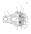
- Fig. 1 shows a switchable, hydraulically damping bearing in the form of a switchable engine mount for a motor vehicle in a schematic representation.
- Such motor bearings 2 are known per se, so that the basic structure is to be explained only briefly here. Here, only the components of the known motor bearing will be discussed, which are relevant to the invention.
- the engine mount 2 is rotationally symmetrical to its longitudinal axis and includes a pin 4, on which the engine of a motor vehicle is suspended. Further, the engine mount 2 includes a working chamber 6 and a compensation chamber 8, which are each filled with hydraulic fluid and separated by a partition wall 10.
- the partition 10 consists of an upper part 12 and a lower part 14 and includes an annular channel 16, via which the working chamber 6 is connected in a conventional manner with the compensation chamber 8.
- the partition wall 10 includes a bypass channel 18.
- a disc-shaped membrane 20 made of iron or other ferromagnetic material whose cross section corresponds to the cross section of the bypass channel 18.
- the membrane 20 is arranged in the partition wall 10 or in the bypass channel 18 such that it can be deflected in the longitudinal direction of the bearing.
- the freedom of movement of the membrane 20 upwards is limited by a stop 22 on the upper part 12.
- the freedom of movement of the membrane downwards is limited by a stop 24 on the lower part 14.
- the surface of the diaphragm 20, which faces the working chamber 6, communicates with the hydraulic fluid in the working chamber 6 through the opening 26 in the upper part 12. Furthermore, the underside of the membrane 20 is connected via an annular channel 28 with the hydraulic fluid in the compensation chamber 8 in connection.
- the engine mount further includes an electromagnetic switching actuator 30, with which the ferromagnetic membrane 20 is switchable.
- the switch actuator 30 is disposed below the diaphragm 20 on the side of the partition wall 10, which faces away from the working chamber 6. It is designed such that it exerts a magnetic holding force on the membrane 20 in the currentless state and fixes the membrane 20 in a rest position.
- the membrane 20 is in its rest position on the stop 24 of the lower part 14 of the partition 10, so that the bypass channel 18 is blocked.
- the switching actuator 30 is designed such that it reduces the magnetic holding force in the current-carrying state so far that the membrane 20 is released for movement in the longitudinal direction of the engine mount 2. The membrane 20 can then move freely between the stop 22 and the stop 24 and releases the bypass channel 18.
- the engine mount 2 includes an annular decoupling membrane 32 which lies between the upper part 12 and the lower part 14 of the partition wall 10 and comprises the magnetic membrane 20.
- the top of the decoupling membrane 32 is acted upon by windows 34 in the upper part 12 with the Hydraulikflüssikeit in the working chamber 6.
- the underside of the decoupling membrane 32 is acted upon by windows 36 in the lower part 14 with the hydraulic fluid in the compensation chamber 8.
- the operation of the switchable engine mount is as follows: when vibrations are introduced into the engine mount 2 in the normal driving mode via the engine (not shown), hydraulic fluid is transferred from the working chamber 6 via the annular passage 16 into the balancing chamber 8 (or vice versa) , Here, due to the throttling action of the annular channel 16, the vibrations introduced into the bearing are damped. During the initiation of these vibrations, the membrane 20 is fixed by means of the switching actuator 30 in its rest position and takes the in the Fig. 1 shown position. The bypass channel 18 is then closed. For idling vibrations whose frequencies are higher than those in normal driving occurring oscillations, the annular channel 16 is dynamically closed, so that then no hydraulic fluid between the working chamber 6 and the compensation chamber 8 back and forth can be transported.
- the switching actuator 30 is brought into the energized state, so that the magnetic holding force of the Wegaktors 30 reduced to the extent that the membrane 20 is released for movement in the longitudinal direction of the engine mount 2.
- the introduced idling vibrations are then compensated by the volume of the working chamber 6 is kept constant by a movement of the membrane 20 in the bypass channel 18. This is achieved in that the membrane 20 moves freely in the bypass channel 18 up and down (which means that the membrane 20 exclusively by the pressure exerted by the hydraulic fluid in the working chamber 6 and in the compensation chamber 8 on the membrane 20 is moved up and down, the movement of the diaphragm 20 in the bypass channel 18 is not influenced by the latter in the energized state of the switching actuator 30).
- Vibrations with other frequencies, which are introduced into the engine mount 2, can be compensated in a manner known per se with the decoupling membrane 32.
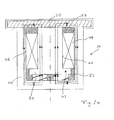
- Fig. 2 shows the electromagnetic switching actuator 30 which is rotationally symmetrical to its longitudinal axis, in a schematic representation.
- the switch actuator 30 is first based on the Fig. 2a explained. It contains an annular permanent magnet 38, a first ferromagnetic element in the form of a pot 40 and a second ferromagnetic element in the form of a ferromagnetic core 42.
- the switching actuator 30 includes an electrically conductive coil 44 (the power supply line to the coil and the current-carrying line from the coil are not shown).
- the annular permanent magnet 38 is disposed on the bottom of the pot 40.
- On the permanent magnet 38 of the ferromagnetic core 42 is applied.
- the core 42 terminates at its upper end with the pot 40 and is sized in width so that between the inner wall 46 of the pot 40 and the Jacket surface 48 of the core 42 remains a gap.
- the coil 44 is wound around the core 42 and fills the gap between the inner wall 46 and the lateral surface 48 from.
- the core 42 includes at its lower end a collar 46 which projects radially outwardly beyond the lateral surface 48 of the core 42. In the region of the collar 50, the gap between the inner wall 46 of the pot 40 and the lateral surface 48 of the core 42 is thus significantly smaller than in the remaining region of the core 42.
- the coil 44 rests on the collar 50.
- the remaining cavities in the pot 40 are potted with a potting compound 52.
- the permanent magnet 38 is formed such that the magnetic field in its interior parallel to the longitudinal axis of the Wegaktors 30 from bottom to top (indicated by the arrows in the permanent magnet 38).
- the magnetic field generated by the permanent magnet 38 is guided in the currentless state of the Wegaktors inside the coil 44 through the ferromagnetic core 42 parallel to the longitudinal axis of the Wegaktors 30.
- the magnetic field lines exit from the pot 40 and are deflected in the ferromagnetic membrane 20, as in the Fig. 2a is shown.
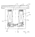
- the switching actuator 30 behaves in the energized state.
- the coil 44 is such a current sent that a magnetic field is built up by the coil 44, which is indicated by the arrows 54 and 56.
- the magnetic field of the coil 44 extends in its interior through the core 42 from the upper end to the lower end of the pot 40.
- the magnetic field generated by the coil 44 extends from bottom to top, as indicated by the magnetic field lines 54 and 56 is.
- the magnetic field lines 54, 56 are closed at their lower end via the collar 50 and at its upper end via the potting compound 52.
- the magnetic field lines 54, 56 generated by the current-carrying coil 44 thus extend in their orientation in the reverse direction, as in the Fig.
- the transfer of the switching actuator 30 from the de-energized state to the energized state and vice versa is made as required by a control unit of the motor vehicle in which the engine mount is installed.
- the ferromagnetic membrane 20 is embedded in a rubber layer 58.
- the coil 44 is located between the diaphragm 20 and the permanent magnet 38 and the longitudinal direction of the pot 40 is parallel to the longitudinal direction of the bearing 2.
- Fig. 3 shows an engine mount 2, which is constructed largely the same as that in the Fig. 1
- the switch actuator 30 is constructed the same as it is in connection with the Fig.2 has been explained.
- the only difference to the engine mount 2 according to the Fig. 1 is to be seen in that the disc-shaped membrane 20 is clamped at its edge between the upper part 12 and the lower part 14 of the partition wall 10, wherein the membrane 20 is acted upon on the surface facing the working chamber 6, with hydraulic fluid, and on the Surface facing away from the working chamber 6, is exposed to air.
- Engine mounts 2 shown no additional Entkoppelungsmembran.
- Fig. 4 shows an engine mount 2 with a switching actuator 30, which is constructed the same as it is in connection with the Fig. 1 to 3 has been explained.
- the partition 10 of the switching actuator 2 includes a first diaphragm 20 which is controllable by means of the switching actuator 30.
- the membrane 20 consists of a circular metal plate 60 which is embedded in the elastomer of the membrane 20. Furthermore, the first membrane 20 is an integral part of the rolling diaphragm 74, which limits the compensation chamber 8 to the outside.
- the partition wall 10 includes a second membrane 62 which is deflectable in the longitudinal direction of the engine mount 2 and with which the volume of the working chamber 6 (see Fig. 4a ) can be influenced in a manner known per se.
- an air chamber 64 is arranged between the first membrane 20 and the second membrane 62.
- the air chamber 64 is closed airtight to the atmosphere in the de-energized state of the Wegaktors 30.
- the second diaphragm 62 must be at a deformation of the working chamber 6 (see Fig. 4a ) then operate against the air pressure in the air chamber 64, so that the engine mount 2 is set hard.
- the air chamber 64 In the energized state of the Heidelbergaktors 30, the air chamber 64 is in communication with the atmosphere.
- the second diaphragm 62 then needs to work with a change in volume of the working chamber 6 exclusively against the atmospheric air pressure, so that the engine mount 2 is set soft.
- the air chamber 64 can be hermetically sealed to the atmosphere or associated with the atmosphere. This is based on the Fig. 4b first described the state in which the air chamber 64 is sealed airtight to the atmosphere.
- an annular sealing lip 66 of the first diaphragm 20 rests on a sealing seat 68, which comprises the switching actuator 30.
- ventilation slots 70a and 70b which extend radially outward on the pot 40 of the switching actuator 30 in the longitudinal direction of the bearing 2 along.
- the ventilation slots 70a and 70b communicate with the atmosphere.
- Radially outside the sealing lip 66, the membrane 20 includes windows 70a, 70b.
- Fig. 5 shows a section along the line V / V.
- the membrane 20 includes distributed over its circumference a plurality of windows 72a, 72b (preferably, the membrane 20 includes at least four windows 72).
- a plurality of ventilation slots 70a, 70b are arranged distributed in the immediate radial vicinity of the switching actuator 30 over the circumference (preferably at least four ventilation slots 70 are arranged over the entire circumference in the immediate vicinity of the switching actuator 30).
- the windows 72 in the membrane 20 and the ventilation slots 70 are dimensioned so that the cross-sectional area of the windows in total is greater than the cross-sectional area of the ventilation slots in total. This prevents that the membrane by the air flow to the sealing seat 68 (s. Figure 4 ) is pressed when the air escapes from the air chamber 64 via the windows 72 and the ventilation slots 70 into the atmosphere.
Landscapes
- Engineering & Computer Science (AREA)
- General Engineering & Computer Science (AREA)
- Mechanical Engineering (AREA)
- Combined Devices Of Dampers And Springs (AREA)
Description
- Die Erfindung betrifft ein schaltbares, hydraulisch dämpfendes Lager, insbesondere Motorlager für ein Kraftfahrzeug, das folgende Bestandteile enthält:
- eine mit einer Hydraulikflüssigkeit gefüllte Arbeitskammer,
- eine Ausgleichskammer, die über einen Kanal mit der Arbeitskammer verbunden ist,
- eine Trennwand, die die Arbeitskammer von der Ausgleichskammer trennt,
- mindestens eine ferromagnetische magnetische Membran, die in der Trennwand derart angeordnet ist, dass sie in Längsrichtung des Lagers auslenkbar ist,
- einen elektromagnetischen Schaltaktor, mit dem die Membran steuerbar ist.
- Ein Motorlager der eingangs genannten Art ist aus der
US 4,789,142 bekannt. Bei dem aus dieser Druckschrift bekannten Motorlager weist die Trennwand zusätzlich zu dem Kanal, durch den die Hydraulikflüssigkeit zwischen der Arbeitskammer und der Ausgleichskammer hin- und her strömen kann, eine Bypass-Öffnung auf. In der Bypass-Öffnung liegt die ferromagnetische Membran, die in Längsrichtung des Motorlagers gesehen einen oberen und unteren Anschlag hat. Unterhalb der Membran und unterhalb der Ausgleichskammer ist ein elektromagnetischer Schaltaktor in Form einer elektrisch leitenden Spule angeordnet, mit dem die Membran gesteuert werden kann. So kann die Spule derart bestromt werden, dass sich die Membran entweder in ihrer unteren oder in ihrer oberen Anschlagsposition befindet, in der die Bypass Öffnung jeweils verschlossen ist. Darüber hinaus ist es möglich, die Spule derart zu bestromen, dass die Membran jede beliebige Position zwischen der unteren und der oberen Anschlagsposition einnimmt. Die Membran gibt dann die Bypass-Öffnung frei, so dass Hydraulikflüssigkeit zwischen der Arbeitskammer und der Ausgleichskammer hin- und her strömen kann. Durch gezielte Einstellung der Position der Membran zwischen dem oberen und dem unteren Anschlag mit Hilfe der Spule kann darüber hinaus das Volumen der Arbeitskammer an die aktuellen Anforderungen an das Motorlager angepasst werden. Mit dem aus derUS 4,789,142 bekannten Hydrolager können niedrigfrequente Schwingungen gedämpft werden, indem Hydraulikflüssigkeit über den Kanal zwischen der Arbeitskammer und der Ausgleichskammer des Motorlagers hin- und her strömt. Darüber hinaus können hochfrequente Schwingungen, die in das Motorlager eingeleitet werden, dadurch von der Karosserie des Kraftfahrzeuges ferngehalten werden, dass mit Hilfe der ferromagnetischen Membran der Bypass geöffnet wird und die Membran so durch die Spule angesteuert wird, dass das Volumen der Arbeitskammer annähernd konstant bleibt. Es ist jedoch festzustellen, dass die Spule des elektromagnetischen Schaltaktors ständig bestromt werden muss, um die Membran zu steuern. Dies gilt sowohl für den Fall, dass die Membran in der oberen oder der unteren Anschlagposition gehalten werden soll, als auch für den Fall, dass die Membran zwischen diesen Positionen gehalten werden soll. Dies führt zu einem hohen Stromverbrauch des elektromagnetischen Schaltaktors. - Der Erfindung liegt die Aufgabe zugrunde, ein schaltbares, hydraulisch dämpfendes Lager, insbesondere ein Motorlager für ein Kraftfahrzeug, zu schaffen, das einen niedrigen Stromverbrauch hat.
- Die Aufgabe wird gemäß den kennzeichnenden Merkmalen des Anspruchs 1 dadurch gelöst, dass der Schaltaktor derart ausgebildet ist, dass er im stromlosen Zustand eine magnetische Haltekraft auf die Membran ausübt und die Membran in einer Ruhelage fixiert und er im stromführenden Zustand die magnetische Haltekraft soweit reduziert, dass die Membran für eine Bewegung in Längsrichtung des Lagers freigegeben wird.
- Der Vorteil der Erfindung ist darin zu sehen, dass der elektromagnetische Schaltaktor und damit das schaltbare Lager nur einen geringen Stromverbrauch haben. Dies wird verständlich, wenn man das Folgende berücksichtigt: Schwingungen im Fahrbetrieb des Fahrzeuges werden mit Hilfe des schaltbaren Lagers dadurch gedämpft, das Hydraulikflüssigkeit über den Kanal zwischen der Arbeitskammer und der Ausgleichskammer hin- und her strömt. Schwingungen im Leerlauf des Fahrzeuges (im Folgenden als Leerlaufschwingungen bezeichnet; diese entstehen bei laufendem Motor z.B. dann, wenn dass Fahrzeug im Leerlauf an einer roten Ampel steht), die auf das Lager einwirken, werden hingegen mit Hilfe der Membran beeinflusst, die dazu in Längsrichtung des Lagers frei beweglich sein muss. Im normalen Fahrbetrieb wird eine Bewegungsfreiheit der Membran nicht benötigt wird, so dass sie in ihrer Ruhelage fixiert sein kann. Erfindungsgemäß benötigt der elektromagnetische Schaltaktor dann keinen Strom. Vielmehr benötigt der elektromagnetische Schaltaktor nur Strom, wenn Leerlaufschwingungen auf das Motorlager einwirken.
- Eine Weiterbildung nach Anspruch 2 ist dadurch gekennzeichnet, dass der Schaltaktor folgende Bestandteile enthält:
- einen Permanentmagneten,
- ferromagnetische Elemente,
- eine elektrisch leitfähige Spule, durch die im stromführenden Zustand des Schaltaktors ein Strom fließt,
- Der Vorteil dieser Weiterbildung ist darin zu sehen, dass die Membran mit Hilfe des Permanentmagneten sicher in ihrer Ruhelage fixiert werden kann, da mit Hilfe des Permanentmagneten eine große magnetische Kraft auf die Membran ausgeübt werden kann. Ein weiterer Vorteil der Weiterbildung ist, dass der Schaltaktor ein geringes Bauvolumen hat, da bereits mit einem kleinen Permanentmagneten eine ausreichend große magnetische Kraft auf die Membran ausgeübt werden kann.
- Eine Weiterbildung der Erfindung nach Anspruch 3 ist dadurch gekennzeichnet, dass der Schaltaktor folgende Bestandteile enthält:
- einen Topf aus ferromagnetischem Material, auf dessen Boden der Permanentmagnet derart angeordnet ist, dass das Magnetfeld in dem Permanentmagneten in Längsrichtung des Topfes weist,
- einen ferromagnetischen Kern, der oberhalb des Permanentmagneten angeordnet ist, dessen Längsachse in Längsrichtung des Topfes weist und um dessen Längsachse die
- Der Vorteil dieser Weiterbildung ist darin zu sehen, dass der Schaltaktor einen kompakten Aufbau aufweist.
- Gemäß einer Weiterbildung der Erfindung nach Anspruch 4 ist der Luftspalt zwischen dem Topf und dem Kern mit einer elektrisch isolierenden Vergussmasse vergossen. Der Vorteil dieser Weiterbildung ist darin zu sehen, dass die Spule in dem Schaltaktor durch die Vergussmasse sicher in ihrer Position fixiert wird. Ein weiterer Vorteil der Erfindung ist darin zu sehen, dass die Bestandteile des Schaltaktors durch die Vergussmasse vor Umwelteinflüssen geschützt sind.
- Gemäß einer Weiterbildung der Erfindung nach Anspruch 5 ist der Schaltaktor auf der Seite der Trennwand angeordnet, die der Arbeitskammer abgewandt ist. Der Vorteil dieser Weiterbildung ist darin zu sehen, dass der Schaltaktor außerhalb der Arbeitskammer angeordnet ist und somit das Volumen der Arbeitskammer durch den Schaltaktor nicht reduziert wird.
- Eine Weiterbildung der Erfindung nach Anspruch 6 ist dadurch gekennzeichnet, dass
- die Trennwand ein Oberteil und ein Unterteil enthält und einen Bypasskanal aufweist, der die Arbeitskammer mit der Ausgleichskammer verbindet,
- und dass die Membran in dem Bypasskanal liegt und in Querschnitt dem Querschnitt des Bypasskanals entspricht,
- Der Vorteil dieser Weiterbildung wird verständlich, wenn man folgendes berücksichtigt: im stromlosen Zustand des Schaltaktors kann sich die Membran in dem Bypasskanal frei bewegen. Da der Querschnitt der Membran jedoch dem Querschnitt des Bypasskanals entspricht, fließt bei einer Bewegung der Membran in dem Bypasskanal keine Hydraulikflüssigkeit von der Arbeitskammer in die Ausgleichskammer oder in umgekehrte Richtung. Vielmehr wird ausschließlich die Membran nach oben und nach unten bewegt. Ein Vorteil dieser Weiterbildung ist also darin zu sehen, dass mit Hilfe der in dem Bypasskanal frei beweglichen Membran ausschließlich eine Volumenveränderung der Arbeitskammer herbei geführt wird. Durch die Volumenveränderung der Arbeitskammer kann verhindert werden, dass Leerlaufschwingungen über das Motorlager in die Karosserie des Fahrzeuges eingeleitet werden. Ferner tritt keine dynamische flüssigkeitsbedingte Verhärtung der Arbeitskammer auf, da die Hydraulikflüssigkeit aus der Arbeitskammer abfließen kann.
- Gemäß einer Weiterbildung der Erfindung nach Anspruch 7 ist die Membran in dem Bypasskanal von einer ringförmigen Entkopplungsmembran umgeben, die zwischen dem Oberteil und dem Unterteil der Trennwand liegt. Der Vorteil dieser Weiterbildung ist darin zu sehen, dass mit Hilfe der ringförmigen Entkopplungsmembran Schwingungen in einem anderen Frequenzbereich beeinflusst werden können, als es mit der Membran möglich ist, die mit Hilfe des elektromagnetischen Schaltaktors angesteuert wird. Das schaltbare Lager wird somit in seiner Wirkung breitbandiger.
- Gemäß einer Weiterbildung der Erfindung nach Anspruch 8 ist die Membran scheibenförmig ausgebildet und an ihrem Rand zwischen einem Oberteil und einem Unterteil der Trennwand eingespannt, wobei die Membran auf der Oberfläche, die der Arbeitskammer zugewandt ist, mit Hydraulikflüssigkeit beaufschlag ist, und auf der Oberfläche, die der Arbeitskammer abgewandt ist, mit Luft beaufschlagt ist. Der Vorteil dieser Weiterbildung ist darin zu sehen, dass das Lager bei Leerlaufschwingungen keine dynamische Verhärtung aufweist, da die Luft unter der Membran kompressibel ist.
- Gemäß einer Weiterbildung der Erfindung nach Anspruch 9 ist die Membran in Gummi eingebettet. Der Vorteil dieser Weiterbildung ist darin zu sehen, dass die Membran keine Geräusche verursacht, wenn sie an andere Bestandteile des Schaltaktors, z.B. an die Trennwand anschlägt.
- Gemäß einer Weiterbildung der Erfindung nach Anspruch 10 ist in der Trennwand eine zweite Membran angeordnet, die in Längsrichtung des Lagers auslenkbar ist und die das Volumen der Arbeitskammer beeinflusst, wobei zwischen der ersten Membran und der zweiten Membran eine Luftkammer angeordnet ist, die im stromlosen Zustand des Schaltaktors luftdicht zur Atmosphäre abgeschlossen ist und die im stromführenden Zustand des Schaltaktors mit der Atmosphäre in Verbindung steht. Das schaltbare Lager ist verhärtet, wenn die Luftkammer zur Atmosphäre luftdicht abgeschlossen ist, da sich in diesem Zustand des Lagers die zweite Membran nur geringfügig bewegen kann. Im Gegensatz dazu weist das schaltbare Lager eine weiche Charakteristik auf, wenn die Luftkammer mit der Atmosphäre in Verbindung steht, da sich die zweite Membran dann in Längsrichtung des Lagers entgegen dem Atmosphärenluftdruck bewegen kann. Wenn das schaltbare Lager als Motorlager für ein Kraftfahrzeug genutzt wird, wird die Luftkammer dann mit der Atmosphäre verbunden, wenn auf das Lager Leerlaufschwingungen einwirken. Der Vorteil der Weiterbildung ist darin zu sehen, dass die erste Membran und die zweite Membran voneinander entkoppelt sind. Dies führte dazu, dass die erste Membran mit kleinen Kräften gesteuert werden kann, da sie nicht den Kräften, die von der Ausgleichkammer auf die zweite Membran wirken, ausgesetzt ist. Dementsprechend braucht der Schaltaktor in dem Lager nur kleine Kräfte zu erzeugen und kann klein ausgebildet werden.
- Gemäß einer Weiterbildung der Erfindung nach Anspruch 11 ist die erste Membran Bestandteil der Rollmembran, die das Volumen der Ausgleichkammer nach außen begrenzt. Der Vorteil dieser Weiterbildung ist darin zu sehen, dass die erste Membran als ein einziges Bauteil mit der Rollmembran in das Lager eingebracht werden kann, was die Produktion des Lagers vereinfacht. Ein weiterer Vorteil der Weiterbildung ist darin zu sehen, dass eine Rollmembran mit einer intrigierten ersten Membran zu geringen Kosten hergestellt werden kann.
- Eine Weiterbildung der Erfindung nach Anspruch 12 ist dadurch gekennzeichnet, dass
- das Lager mindestens einen Belüftungsschlitz aufweist, über den die Luftkammer mit der Atmosphäre verbindbar ist, und dass
- die erste Membran mindestens ein Fenster aufweist, über das die Luftkammer mit dem Belüftungsschlitz verbindbar ist, und dass
- die erste Membran im stromlosen Zustand des Schaltaktors mit einer ringförmigen Dichtlippe derart auf einem Dichtsitz aufliegt, dass die Verbindung für die in der
- Luftkammer befindliche Luft von dem Fenster zum Belüftungsschlitz gesperrt ist. Der Vorteil dieser Weiterbildung ist darin zu sehen, dass über den Querschnitt der Belüftungsschlitze die Dämpfungscharakteristik des Lagers im hochfrequenten Bereich eingestellt werden kann.
- Gemäß einer Weiterbildung der Erfindung nach Anspruch 13 verläuft der mindestens eine Belüftungsschlitz radial außen am Topf des Schaltaktors. Der Vorteil dieser Weiterbildung ist darin zu sehen, dass die Belüftungsschlitze in direkter Nachbarschaft zu dem Schaltaktor liegen, so dass sie durch die Dichtlippe einfach von dem Fenster der ersten Membran getrennt werden können.
- Ein Ausführungsbeispiel und weitere Vorteile der Erfindung werden im Zusammenhang mit den nachstehenden Figuren erläutert, darin zeigt:
- Fig. 1
- ein schaltbares Lager,
- Fig. 2
- den Schaltaktor,
- Fig. 3
- ein schaltbares Lager
- Fig. 4
- ein schaltbares Lager
- Fig. 5
- einen Schnittentlang der Linie VN in
Fig. 4b . -
Fig. 1 zeigt ein schaltbares, hydraulisch dämpfendes Lager in Form eines schaltbaren Motorlagers für ein Kraftfahrzeug in schematischer Darstellung. Derartige Motorlager 2 sind an sich bekannt, so dass der grundsätzliche Aufbau hier nur kurz erläutert werden soll. Hierbei wird ausschließlich auf die Bestandteile des an sich bekannten Motorlagers eingegangen, die für die Erfindung relevant sind. Das Motorlager 2 ist rotationssymmetrisch zu seiner Längsachse und enthält einen Zapfen 4, an dem der Motor eines Kraftfahrzeuges aufgehängt wird. Ferner enthält das Motorlager 2 eine Arbeitskammer 6 und eine Ausgleichskammer 8, die jeweils mit Hydraulikflüssigkeit gefüllt und durch eine Trennwand 10 voneinander getrennt sind. Die Trennwand 10 besteht aus einem Oberteil 12 und einem Unterteil 14 und enthält einen Ringkanal 16, über den die Arbeitskammer 6 in an sich bekannter Art und Weise mit der Ausgleichskammer 8 verbunden ist. Darüber hinaus enthält die Trennwand 10 einen Bypasskanal 18. In dem Bypasskanal 18 liegt eine scheibenförmige Membran 20 aus Eisen oder einem anderen ferromagnetischen Material, deren Querschnitt dem Querschnitt des Bypasskanals 18 entspricht. Die Membran 20 ist in der Trennwand 10 bzw. in dem Bypasskanal 18 derart angeordnet, dass sie in Längsrichtung des Lagers auslenkbar ist. Hierbei wird der Bewegungsfreiraum der Membran 20 nach oben (also in Richtung der Arbeitskammer) durch einen Anschlag 22 an dem Oberteil 12 begrenzt. Zusätzlich wird der Bewegungsfreiraum der Membran nach unten (also in Richtung der Ausgleichskammer 8) durch einen Anschlag 24 am Unterteil 14 begrenzt. Die Oberfläche der Membran 20, die der Arbeitskammer 6 zugewandt ist, steht mit der Hydraulikflüssigkeit in der Arbeitskammer 6 durch die Öffnung 26 in dem Oberteil 12 in Verbindung. Ferner steht die Unterseite der Membran 20 über ein Ringkanal 28 mit der Hydraulikflüssigkeit in der Ausgleichskammer 8 in Verbindung. - Neben den bisher genannten Bestandteilen enthält das Motorlager ferner einen elektromagnetischen Schaltaktor 30, mit dem die ferromagnetische Membran 20 schaltbar ist. Der Schaltaktor 30 ist unterhalb der Membran 20 auf der Seite der Trennwand 10 angeordnet, die der Arbeitskammer 6 abgewandt ist. Er ist derart ausgebildet, dass er im stromlosen Zustand eine magnetische Haltekraft auf die Membran 20 ausübt und die Membran 20 in einer Ruhelage fixiert. Bei dem in der
Figur 1 gezeigten Auführungsbeispiel des Motorlagers 2 liegt die Membran 20 in ihrer Ruhelage auf dem Anschlag 24 des Unterteils 14 der Trennwand 10 auf, so dass der Bypasskanal 18 versperrt ist. Ferner ist der Schaltaktor 30 derart ausgebildet, dass er im stromführenden Zustand die magnetische Haltekraft soweit reduziert, dass die Membran 20 für eine Bewegung in Längsrichtung des Motorlagers 2 freigegeben wird. Die Membran 20 kann sich dann frei zwischen dem Anschlag 22 und dem Anschlag 24 bewegen und gibt den Bypasskanal 18 frei. - Zusätzlich zu den bisher genannten Bestandteilen enthält das Motorlager 2 eine ringförmige Entkopplungsmembran 32, die zwischen dem Oberteil 12 und dem Unterteil 14 der Trennwand 10 liegt und die magnetische Membran 20 umfasst. Die Oberseite der Entkopplungsmembran 32 wird durch Fenster 34 in dem Oberteil 12 mit der Hydraulikflüssikeit in der Arbeitskammer 6 beaufschlagt. Die Unterseite der Entkopplungsmembran 32 wird durch Fenster 36 in dem Unterteil 14 mit der Hydraulikflüssigkeit in der Ausgleichskammer 8 beaufschlagt.
- Die Funktionsweise des schaltbaren Motorlagers ist wie folgt: wenn im normalen Fahrbetrieb über den (nicht gezeigten) Motor Schwingungen in das Motorlager 2 eingeleitet werden, wird Hydraulikflüssigkeit von der Arbeitskammer 6 über den Ringkanal 16 in die Ausgleichskammer 8 (bzw. in umgekehrter Richtung) überführt. Hierbei werden aufgrund der Drosselwirkung des Ringkanals 16 die in das Lager eingeleiteten Schwingungen gedämpft. Während der Einleitung dieser Schwingungen wird die Membran 20 mit Hilfe des Schaltaktors 30 in ihrer Ruhelage fixiert und nimmt die in der
Fig. 1 gezeigte Position ein. Der Bypasskanal 18 ist dann verschlossen. Für Leerlaufschwingungen, deren Frequenzen höher liegen, als die im normalen Fahrbetrieb auftretenden Schwingungen, ist der Ringkanal 16 dynamisch verschlossen, so dass dann keine Hydraulikflüssigkeit zwischen der Arbeitskammer 6 und der Ausgleichskammer 8 hin- und her transportiert werden kann. Während der Einleitung von Leerlaufschwingungen in das Motorlager 2 wird der Schaltaktor 30 in den stromführenden Zustand überführt, so dass sich die magnetische Haltekraft des Schaltaktors 30 soweit reduziert, dass die Membran 20 für eine Bewegung in Längsrichtung des Motorlagers 2 freigegeben wird. Die eingeleiteten Leerlaufschwingungen werden dann dadurch ausgeglichen, dass durch eine Bewegung der Membran 20 in dem Bypasskanal 18 das Volumen der Arbeitskammer 6 konstant gehalten wird. Dies erfolgt dadurch, dass die Membran 20 sich in dem Bypasskanal 18 frei auf und ab bewegt (das bedeutet, dass die Membran 20 ausschließlich durch den Druck, der von der Hydraulikflüssigkeit in der Arbeitskammer 6 bzw. in der Ausgleichskammer 8 auf die Membran 20 ausgeübt wird, auf und ab bewegt wird; die Bewegung der Membran 20 in dem Bypasskanal 18 wird im stromführenden Zustand des Schaltaktors 30 nicht durch diesen beeinflusst). - Schwingungen mit weiteren Frequenzen, die in das Motorlager 2 eingeleitet werden, können in an sich bekannter Art und Weise mit der Entkopplungsmembran 32 ausgeglichen werden.
-
Fig. 2 zeigt den elektromagnetischen Schaltaktor 30, der rotationssymmetrisch zu seiner Längsachse ist, in schematischer Darstellung. Hierbei zeigtFig. 2a den stromlosen Zustand des Schaltaktors 30 und dieFig. 2b den stromführenden Zustand des Schaltaktors 30. Der Schaltaktor 30 wird zunächst anhand derFig. 2a erläutert. Er enthält einen ringförmigen Permanentmagneten 38, ein erstes ferromagnetisches Element in Form eines Topfes 40 und ein zweites ferromagnetisches Element in Form eines ferromagnetischen Kernes 42. Darüber hinaus enthält der Schaltaktor 30 eine elektrisch leitfähige Spule 44 (die stromzuführende Leitung zu der Spule und die stromableitende Leitung von der Spule sind nicht gezeigt). Der ringförmige Permanentmagnet 38 ist auf den Boden des Topfes 40 angeordnet. Auf dem Permanentmagneten 38 ist der ferromagnetische Kern 42 aufgebracht. Der Kern 42 schließt an seinem oberen Ende mit dem Topf 40 ab und ist in seiner Breite so bemessen, dass zwischen der Innenwand 46 des Topfes 40 und der Mantelfläche 48 des Kerns 42 ein Spalt verbleibt. Die Spule 44 ist um den Kern 42 gewickelt und füllt den Spalt zwischen der Innenwand 46 und der Mantelfläche 48 aus. Der Kern 42 enthält an seinem unteren Ende einen Kragen 46 der nach radial außen über die Mantelfläche 48 des Kerns 42 hinausragt. Im Bereich des Kragens 50 ist der Spalt zwischen der Innenwand 46 des Topfes 40 und der Mantelfläche 48 des Kerns 42 also deutlich kleiner als im übrigen Bereich des Kerns 42. Die Spule 44 liegt auf dem Kragen 50 auf. Die verbleibenden Hohlräume in dem Topf 40 werden mit einer Vergussmasse 52 vergossen. - Im Folgenden wird die Funktionsweise des Schaltaktors 30 im stromlosen Zustand erläutert: der Permanentmagnet 38 ist derart ausgebildet, dass das Magnetfeld in seinem Inneren parallel zur Längsachse des Schaltaktors 30 von unten nach oben verläuft (angedeutet durch die Pfeile im Permanentmagneten 38). Das von dem Permanentmagneten 38 erzeugte Magnetfeld wird im stromlosen Zustand des Schaltaktors im Inneren der Spule 44 durch den ferromagnetischen Kern 42 parallel zur Längsachse des Schaltaktors 30 geführt. Am oberen Ende des Topfes treten die Magnetfeldlinien aus dem Topf 40 aus und werden in der ferromagnetischen Membran 20 so umgelenkt, wie es in der
Fig. 2a gezeigt ist. Radial außen treten die Magnetfeldlinien in den Topf 40 des Schaltaktors 30 ein und verlaufen parallel der Längsachse des Schaltaktors 30 bis zum unteren Ende des Topfes 40. Schließlich werden die Magnetfeldlinien im Boden des Topfes 40 so umgelenkt, wie es in derFig. 2a gezeigt ist und treffen schließlich wieder auf den Permanentmagneten 38. Somit werden die von dem Permanentmagneten 38 ausgehenden Magnetfeldlinien über den Kern 42, die ferromagnetische Membran 20 und den Topf 40 geschlossen. Aufgrund der geschlossenen Magnetfeldlinien wird auf die Membran 20 eine magnetische Haltekraft ausgeübt, die die Membran 20 in der Ruhelage fixiert, in der sie, wie in derFig. 2a gezeigt, auf dem Topf 40 aufliegt. Die radial äußeren Enden der Membran 20 liegen dann, wie in derFig. 1 gezeigt, auf dem Anschlag 24 des Unterteils 14 der Trennwand 10 auf. - Im Zusammenhang mit der
Fig. 2b wird im Folgenden erläutert, wie sich der Schaltaktor 30 im stromführenden Zustand verhält. Durch die Spule 44 wird derart ein Strom geschickt, dass durch die Spule 44 ein Magnetfeld aufgebaut wird, dass durch die Pfeile 54 und 56 angedeutet ist. Das Magnetfeld der Spule 44 verläuft in ihrem Inneren durch den Kern 42 vom oberen Ende zum unteren Ende des Topfes 40. Im Topf 40 verläuft das durch die Spule 44 erzeugte Magnetfeld von unten nach oben, so wie es auch durch die Magnetfeldlinien 54 und 56 angedeutet ist. Die Magnetfeldlinien 54, 56 werden an ihrem unteren Ende über den Kragen 50 und an ihrem oberen Ende über die Vergussmasse 52 geschlossen. Die durch die stromführenden Spule 44 erzeugten Magnetfeldlinien 54, 56 verlaufen also in ihrer Orientierung in der umgekehrten Richtung, wie die in derFig. 2a gezeigten Magnetfeldlinien, die durch den Permanentmagneten 38 erzeugt werden. Dies führt dazu, dass die in derFig. 2a gezeigten Magnetfeldlinien von den Magnetfeldlinien 54, 56 der Spule 44 verdrängt werden und nicht mehr durch den Kern 42 in die Membran 20 verlaufen können. Vielmehr werden die von den Permanentmagneten 38 ausgehende Magnetfeldlinien über den Kragen 50 kurzgeschlossen, verlaufen also ausgehend von den Permanentmagneten 38 durch den Kragen 50 in den Topf 40, den Boden des Topfes 40 und von dort zurück in den Permanentmagneten 38, sowie es in derFig. 2b gezeigt ist. Durch diesen definierten Kurzschluss der Magnetfeldlinien über den Kragen 20 des Kerns 42 ist die magnetische Haltekraft des Permanentmagneten soweit reduziert, dass der Permanentmagnet 38 die Membran 20 nicht mehr in ihrer Ruhelage fixieren kann. Die Membran 20 wird auch nicht durch das Magnetfeld der Spule 44 in ihrer Ruhelage fixiert, da dies zu schwach ist. Die Membran 20 ist also für eine Bewegung in Längsrichtung des Lagers (sieheFig. 1 ) freigegeben. - Die Überführung des Schaltaktors 30 von dem stromlosen Zustand in den stromführenden Zustand und umgekehrt wird nach Bedarf von einer Steuereinheit des Kraftfahrzeuges vorgenmmen, in das das Motorlager eingebaut ist.
- Vorzugsweise ist die ferromagnetische Membran 20 in eine Gummischicht 58 eingebettet. Ferner ist der in der
Fig.2 gezeigte Schaltaktor 30 derart in dem Motorlager 2 (s.Fig.1 ) angeordnet, dass die Spule 44 zwischen der Membran 20 und dem Permanentmagneten 38 liegt und die Längsrichtung des Topfes 40 parallel zur Längsrichtung des Lagers 2 verläuft. -
Fig. 3 zeigt ein Motorlager 2, das weitgehend genauso aufgebaut ist, wie das in derFig. 1 gezeigte Motorlager 2. Insbesondere ist der Schaltaktor 30 genauso aufgebaut, wie es im Zusammenhang mit derFig.2 erläutert worden ist. Der einzige Unterschied zum Motorlager 2 gemäß derFig. 1 ist darin zu sehen, dass die scheibenförmige Membran 20 an ihrem Rand zwischen dem Oberteil 12 und dem Unterteil 14 der Trennwand 10 eingespannt ist, wobei die Membran 20 auf der Oberfläche, die der Arbeitskammer 6 zugewandt ist, mit Hydraulikflüssigkeit beaufschlag ist, und auf der Oberfläche, die der Arbeitskammer 6 abgewandt ist, mit Luft beaufschlagt ist. Ferner enthält das in derFig.3 gezeigte Motorlager 2 keine zusätzliche Entkoppelungsmembran. -
Fig. 4 zeigt ein Motorlager 2 mit einem Schaltaktor 30, der genauso aufgebaut ist, wie es im Zusammenhang mit denFig. 1 bis 3 erläutert worden ist. Bei der nachfolgenden Figurenbeschreibung wird Bezug auf dieFig. 4b genommen, die einen vergrößerten Ausschnitt aus derFig. 4a zeigt. Die Trennwand 10 des Schaltaktors 2 enthält eine erste Membran 20, die mit Hilfe des Schaltaktors 30 steuerbar ist. Die Membran 20 besteht aus einer kreisförmigen Metallplatte 60, die in das Elastomer der Membran 20 eingebettet ist. Ferner ist die erste Membran 20 integraler Bestandteil der Rollmembran 74, die die Ausgleichkammer 8 nach außen begrenzt. Zusätzlich zu der ersten Membran 20 enthält die Trennwand 10 eine zweite Membran 62, die in Längsrichtung des Motorlagers 2 auslenkbar ist und mit der das Volumen der Arbeitskammer 6 (sieheFig. 4a ) in an sich bekannter Art und Weise beeinflussbar ist. Zwischen der ersten Membran 20 und der zweiten Membran 62 ist eine Luftkammer 64 angeordnet. Die Luftkammer 64 ist im stromlosen Zustand des Schaltaktors 30 luftdicht zur Atmosphäre abgeschlossen. Die zweite Membran 62 muss bei einer Verformung des Arbeitskammer 6 (sieheFig. 4a ) dann gegen den Luftdruck in der Luftkammer 64 arbeiten, so dass das Motorlager 2 hart eingestellt ist. Im stromführenden Zustand des Schaltaktors 30 steht die Luftkammer 64 mit der Atmosphäre in Verbindung. Die zweite Membran 62 braucht dann bei einer Volumenänderung der Arbeitskammer 6 ausschließlich gegen den Atmosphärenluftdruck zu arbeiten, so dass das Motorlager 2 weich eingestellt ist. - Im Folgenden wird erläutert, wie die Luftkammer 64 luftdicht zur Atmosphäre abgeschlossen bzw. mit der Atmosphäre in Verbindung gebracht werden kann. Hierbei wird anhand der
Fig. 4b zunächst der Zustand beschrieben, in dem die Luftkammer 64 luftdicht zur Atmosphäre abgeschlossen ist. In diesem Fall liegt eine ringförmige Dichtlippe 66 der ersten Membran 20 auf einem Dichtsitz 68, der den Schaltaktor 30 umfasst, auf. Im radial innen liegenden Bereich der Dichtlippe 66 befinden sich Belüftungsschlitze 70a und 70b, die radial außen am Topf 40 des Schaltaktors 30 in Längsrichtung des Lagers 2 entlang verlaufen. Die Belüftungsschlitze 70a und 70b stehen mit der Atmosphäre in Verbindung. Radial außerhalb der Dichtlippe 66 enthält die Membran 20 Fenster 70a, 70b. Im stromlosen Zustand des Aktors, wenn also die Membran 20 mit der Dichtlippe 66 auf dem Dichtsitz 68 aufsitzt, ist eine Verbindung der Fenster 72a, 72b zu den Belüftungsschlitzen 70a, 70b durch die ringförmige Dichtlippe 66 gesperrt. Dementsprechend kann keine Luft aus der Luftkammer 64 über die Belüftungsschlitze 70a, 70b in die Atmosphäre entweichen. Im stromführenden Zustand des Schaltaktors hebt die Dichtlippe 66 vom Dichtsitz 68 ab (dieser Zustand ist in derFig. 4b gezeigt), so dass die Luftkammer 64 über die Fenster 72a, 72b und über die Belüftungsschlitze 70a, 70b mit der Atmosphäre in Verbindung steht. -
Fig. 5 zeigt einen Schnitt entlang der Linie V/V. Die Membran 20 enthält über ihren Umfang verteilt mehrere Fenster 72a, 72b (vorzugsweise enthält die Membran 20 mindestens vier Fenster 72). Ferner sind in unmittelbarer radialer Nachbarschaft zu dem Schaltaktor 30 über den Umfang verteilt mehrere Belüftungsschlitze 70a, 70b angeordnet (vorzugsweise sind über den gesamten Umfang in unmittelbarerer Nachbarschaft zu dem Schaltaktor 30 mindestens vier Belüftungsschlitze 70 angeordnet). Die Fenster 72 in der Membran 20 und die Belüftungsschlitze 70 sind so bemessen, dass die Querschnittfläche der Fenster in Summe größer ist, als die Querschnittfläche der Belüftungsschlitze in Summe. Hierdurch wird verhindert, dass Die Membran durch den Luftstrom auf den Dichtsitz 68 (s.Fig.4 ) gedrückt wird, wenn die Luft aus der Luftkammer 64 über die Fenster 72 und die Belüftungsschlitze 70 in die Atmosphäre entweicht. -
- 2
- Motorlager
- 4
- Zapfen
- 6
- Arbeitskammer
- 8
- Ausgleichskammer
- 10
- Trennwand
- 12
- Oberteil
- 14
- Unterteil
- 16
- Ringkanal
- 18
- Bypasskanal
- 20
- Membran
- 22
- Anschlag
- 24
- Anschlag
- 26
- Öffnung
- 28
- Ringkanal
- 30
- Schaltaktor
- 32
- Entkopplungsmembran
- 34
- Fenster
- 36
- Fenster
- 38
- Permanentmagnet
- 40
- Topf
- 42
- Kern
- 44
- Spule
- 46
- Innenwand
- 48
- Mantelfläche
- 50
- Kragen
- 52
- Vergussmasse
- 54
- Magnetfeldlinie
- 56
- Magnetfeldlinie
- 58
- Gummischicht
- 60
- Metallplatte
- 62
- Membran
- 64
- Luftkammer
- 66
- Dichtlippe
- 68
- Dichtsitz
- 70a,b
- Belüftungsschlitz
- 72a,b
- Fenster
- 74
- Rollmembran
Claims (13)
- Schaltbares, hydraulisch dämpfendes Lager (2), insbesondere Motorlager für ein Kraftfahrzeug, das folgende Bestandteile enthält:- eine mit einer Hydraulikflüssigkeit gefüllte Arbeitskammer (6),- eine Ausgleichkammer (8), die über einen Kanal (28) mit der Arbeitskammer (6) verbunden ist,- eine Trennwand (10), die die Arbeitskammer (6) von der Ausgleichkammer (8) trennt,- mindestens eine ferromagnetische Membran (20), die in der Trennwand (10) derart angeordnet ist, dass sie in Längsrichtung des Lagers (2) auslenkbar ist,- einen elektromagnetischen Schaltaktor (30), mit dem die Membran (20) steuerbar ist,dadurch gekennzeichnet, dass der Schaltaktor (30) derart ausgebildet ist, dass er im stromlosen Zustand eine magnetische Haltekraft auf die Membran (20) ausübt und die Membran (20) in einer Ruhelage fixiert, und er im stromführenden Zustand die magnetische Haltekraft soweit reduziert, dass die Membran (20) für eine Bewegung in Längsrichtung des Lagers (2) freigeben wird.
- Schaltbares Lager (2) nach Anspruch 1, dadurch gekennzeichnet, dass der Schaltaktor (30) folgende Bestandteile enthält:- einen Permanentmagneten (38),- ferromagnetische Elemente (40, 42),- eine elektrisch leitfähige Spule (44), durch die im stromführenden Zustand des Schaltaktors (30) ein Strom fließt,wobei die genannten Bestandteile des Schaltaktors (30) derart zueinander angeordnet sind, dass sich im stromlosen Zustand des Schaltaktors (30) der von dem Permanentmagneten (38) ausgehende magnetische Fluss über die ferromagnetischen Elemente (40, 42) durch die Membran (20) geführt wird, so dass die Membran (20) durch die von dem Permanentmagneten (20) ausgeübte Haltekraft angezogen wird, und dass im stromführenden Zustand des Schaltaktors (30) der von dem Permanentmagneten (38) ausgehende magnetische Fluss derart umgelenkt wird, dass der magnetische Fluss nicht durch die Membran (20) geführt wird, so dass die von dem Permanentmagneten (38) ausgeübte Haltekraft soweit reduziert ist, dass die Membran (20) für eine Bewegung in Längsrichtung des Lagers (2) freigeben wird.
- Schaltbares Lager (2) nach Anspruch 2, dadurch gekennzeichnet, dass der Schaltaktor (30) folgende Bestandteile enthält:- einen Topf (40) aus ferromagnetischem Material, auf dessen Boden der Permanentmagnet (38) derart angeordnet ist, dass das Magnetfeld in dem Permanentmagneten (38) in Längsrichtung des Topfes (40) weist,- einen ferromagnetischen Kern (42), der oberhalb des Permanentmagneten (38) angeordnet ist, dessen Längsachse in Längsrichtung des Topfes (40) weist und um dessen Längsachse die Spule (44) gewickelt ist, wobei zwischen dem Topf (40) und dem Kern (42) ein Luftspalt verbleibt,wobei der Schaltaktor (30) derart in dem Lager (2) ausgerichtet ist, dass die Spule (44) zwischen der Membran (20) und dem Permanentmagneten (38) liegt und die Längsrichtung des Topfes (40) parallel zur Längsrichtung des Lagers (2) verläuft.
- Schaltbares Lager (2) nach Anspruch 3, dadurch gekennzeichnet, dass der Luftspalt zwischen dem Topf (40) und dem Kern (42) mit einer elektrisch isolierenden Vergußmasse vergossen ist.
- Schaltbares Lager (2) nach einem der Ansprüche 1 bis 4, dadurch gekennzeichnet, dass der Schaltaktor (30) auf der Seite der Trennwand (10) angeordnet ist, die der Arbeitskammer (6) abgewandt ist.
- Schaltbares Lager (2) nach einem der Ansprüche 1 bis 5, dadurch gekennzeichnet, dass- die Trennwand (10) ein Oberteil (12) und ein Unterteil (14) enthält und einen Bypasskanal (18) aufweist, der die Arbeitskammer (6) mit der Ausgleichkammer (8) verbindet,- und dass die Membran (20) in dem Bypasskanal (18) liegt und ihr Querschnitt dem Querschnitt des Bypasskanals (18) entspricht, wobei die Membran (20) den Bypasskanal (18) in der Ruhelage sperrt und wobei die Bewegungsfreiheit der freigegebenen Membran (20) in Längsrichtung des Bypasskanals (18) durch das Oberteil (12) und das Unterteil (14) der Trennwand (10) begrenzt ist.
- SchaltbaresLager (2) nach Anspruch 6, dadurch gekennzeichnet, dass die Membran (20) in dem Bypasskanal (18) von einer ringförmigen Entkoppelungsmembran (32) umgeben ist, die zwischen dem Oberteil (12) und dem Unterteil (14) der Trennwand (10) liegt.
- Schaltbares Lager (2) nach einem der Ansprüche 1 bis 5, dadurch gekennzeichnet, dass die Membran (20) scheibenförmig ausgebildet ist und an ihrem Rand zwischen einem Oberteil (12) und einem Unterteil (14) der Trennwand (10) eingespannt ist und auf der Oberfläche, die der Arbeitskammer (6) zugewandt ist, mit Hydraulikflüssigkeit beaufschlagt ist, und auf der Oberfläche, die der Arbeitskammer (6) abgewandt ist, mit Luft beaufschlagt ist.
- Schaltbares Lager (2) nach einem der Ansprüche 1 bis 8, dadurch gekennzeichnet, dass die Membran (20) in Gummi eingebettet ist.
- Schaltbares Lager (2) nach einem der Ansprüche 1 bis 5, dadurch gekennzeichnet, dass in der Trennwand (10) eine zweite Membran (62) angeordnet ist, die in Längsrichtung des Lagers (2) auslenkbar ist und die das Volumen der Arbeitskammer (6) beeinflusst, wobei zwischen der ersten Membran (20) und der zweiten Membran eine Luftkammer (64) angeordnet ist, die im stromlosen Zustand des Schaltaktors (30) luftdicht zur Atmosphäre abgeschlossen ist und die im stromführenden Zustand des Schaltaktors (30) mit der Atmosphäre in Verbindung steht.
- Schaltbares Lager (2) nach Anspruch 10, dadurch gekennzeichnet, dass die erste Membran (20) Bestandteil der Rollmembran (74) ist, die das Volumen der Ausgleichkammer (8) nach außen begrenzt.
- Schaltbares Lager (2) nach einem der Ansprüche 10 bis 11, dadurch gekennzeichnet, dass- das Lager (2) mindestens einen Belüftungsschlitz (70a, 70b) aufweist, über den die Luftkammer mit der Atmosphäre verbindbar ist, und dass- die erste Membran (20) mindestens ein Fenster (72a, 72b) aufweist, über das die Luftkammer (64) mit dem Belüftungsschlitz (70a, 70b) verbindbar ist, und dass- die erste Membran (20) im stromlosen Zustand des Schaltaktors (30) mit einer ringförmigen Dichtlippe (66) derart auf einem Dichtsitz (68) aufliegt, dass die Verbindung für die in der Luftkammer (64) befindlichen Luft von dem Fenster (72a, 72b) zum Belüftungsschlitz (70a, 70b) gesperrt ist.
- Schaltbares Lager (2) nach Anspruch 12, dadurch gekennzeichnet, dass der mindestens eine Belüftungsschlitz (70a, 70b) radial außen am Topf (40) des Schaltaktors (30) verläuft.
Applications Claiming Priority (3)
| Application Number | Priority Date | Filing Date | Title |
|---|---|---|---|
| DE102010037178 | 2010-08-26 | ||
| DE201010060885 DE102010060885A1 (de) | 2010-08-26 | 2010-11-30 | Motorlager für ein Kraftfahrzeug |
| PCT/EP2011/060086 WO2012025276A1 (de) | 2010-08-26 | 2011-06-17 | Motorlager für ein kraftfahrzeug |
Publications (2)
| Publication Number | Publication Date |
|---|---|
| EP2609347A1 EP2609347A1 (de) | 2013-07-03 |
| EP2609347B1 true EP2609347B1 (de) | 2014-12-17 |
Family
ID=45566288
Family Applications (1)
| Application Number | Title | Priority Date | Filing Date |
|---|---|---|---|
| EP20110725931 Active EP2609347B1 (de) | 2010-08-26 | 2011-06-17 | Motorlager für ein kraftfahrzeug |
Country Status (5)
| Country | Link |
|---|---|
| US (1) | US9022368B2 (de) |
| EP (1) | EP2609347B1 (de) |
| CN (1) | CN103069192B (de) |
| DE (1) | DE102010060885A1 (de) |
| WO (1) | WO2012025276A1 (de) |
Families Citing this family (16)
| Publication number | Priority date | Publication date | Assignee | Title |
|---|---|---|---|---|
| DE102010060886B4 (de) * | 2010-11-30 | 2018-07-12 | Contitech Vibration Control Gmbh | Motorlager für ein Kraftfahrzeug |
| GB201212534D0 (en) * | 2012-07-13 | 2012-08-29 | Dtr Vms Ltd | Hydraulically damped mountinf device |
| DE102012213134A1 (de) * | 2012-07-26 | 2014-01-30 | Zf Friedrichshafen Ag | Hydrolager |
| KR101416415B1 (ko) * | 2013-06-18 | 2014-08-06 | 현대자동차 주식회사 | 진동을 흡수하는 마운팅 장치 |
| DE102013109006B4 (de) * | 2013-08-20 | 2017-07-27 | Trelleborgvibracoustic Gmbh | Hydrolager |
| KR20150085350A (ko) * | 2014-01-15 | 2015-07-23 | 현대모비스 주식회사 | 범프 충격 완화장치 |
| FR3017673B1 (fr) * | 2014-02-14 | 2016-02-12 | Hutchinson | Support antivibratoire hydraulique pilotable |
| KR101612374B1 (ko) | 2015-05-06 | 2016-04-27 | 현대자동차주식회사 | 액티브마운트 |
| FR3054629B1 (fr) * | 2016-07-26 | 2018-08-17 | Hutchinson | Dispositif antivibratoire hydraulique |
| KR102452074B1 (ko) * | 2016-12-06 | 2022-10-06 | 현대자동차주식회사 | 차량의 엔진 마운트 |
| DE102017103603B4 (de) | 2017-02-22 | 2023-03-16 | Dr. Ing. H.C. F. Porsche Aktiengesellschaft | Hydrolager zur Lagerung eines Aggregats eines Kraftfahrzeugs |
| US10899215B2 (en) | 2017-09-11 | 2021-01-26 | Beijingwest Industries Co., Ltd. | Hydraulic mount apparatus |
| CN109083972B (zh) * | 2017-09-11 | 2020-06-30 | 北京京西重工有限公司 | 液压悬置装置 |
| US10690217B2 (en) | 2017-09-11 | 2020-06-23 | Beijingwest Industries Co., Ltd. | Magnetically dynamic damping assembly |
| DE102017218280A1 (de) | 2017-10-12 | 2019-04-18 | Bayerische Motoren Werke Aktiengesellschaft | Vorrichtung, Fortbewegungsmittel und Verfahren zum Beeinflussen eines Übertragungsverhaltens eines dynamischen Motorlagers |
| CN110397697B (zh) * | 2018-09-10 | 2021-02-23 | 北京京西重工有限公司 | 液压悬置装置及分离件 |
Family Cites Families (20)
| Publication number | Priority date | Publication date | Assignee | Title |
|---|---|---|---|---|
| US4789142A (en) | 1987-05-15 | 1988-12-06 | General Motors Corporation | Electronic motor mount with magnetic decoupler |
| JPH07208537A (ja) * | 1994-01-20 | 1995-08-11 | Nippondenso Co Ltd | 液体封入式マウント装置 |
| JP3430699B2 (ja) * | 1995-03-31 | 2003-07-28 | 日産自動車株式会社 | 制御型防振支持装置 |
| DE19743790B4 (de) * | 1996-10-04 | 2004-04-29 | Nissan Motor Co., Ltd., Yokohama | Vorrichtung zur aktiven Vibrationsverringerung |
| JPH11223238A (ja) * | 1998-02-06 | 1999-08-17 | Nissan Motor Co Ltd | 能動型振動制御装置 |
| JP2000283214A (ja) * | 1999-03-30 | 2000-10-13 | Tokai Rubber Ind Ltd | 防振装置用加振器およびそれを用いた能動型防振装置 |
| JP2000310273A (ja) * | 1999-04-23 | 2000-11-07 | Tokai Rubber Ind Ltd | 電磁式能動型防振装置 |
| JP2002195342A (ja) * | 2000-12-28 | 2002-07-10 | Tokai Rubber Ind Ltd | 流体封入式能動型防振装置およびその製造方法 |
| US6439556B1 (en) * | 2001-02-15 | 2002-08-27 | Delphi Technologies, Inc. | Active decoupler hydraulic mount |
| DE10213996A1 (de) * | 2002-03-27 | 2003-10-16 | Freudenberg Carl Kg | Schaltbares Aggregatelager mit hydraulischer Dämpfung |
| JP3811469B2 (ja) * | 2003-06-13 | 2006-08-23 | 本田技研工業株式会社 | 能動型防振支持装置のアクチュエータ駆動制御装置 |
| DE10346309A1 (de) * | 2003-10-06 | 2005-04-28 | Trelleborg Automotive Tech Ct | Hydraulisch dämpfendes Lager |
| WO2005088159A1 (ja) * | 2004-03-12 | 2005-09-22 | Toyo Tire & Rubber Co., Ltd. | 能動型液封入式防振装置 |
| JP3972210B2 (ja) * | 2004-06-15 | 2007-09-05 | 東海ゴム工業株式会社 | 流体封入式能動型防振装置 |
| JP4400742B2 (ja) * | 2004-11-11 | 2010-01-20 | 東海ゴム工業株式会社 | 能動型防振装置 |
| US8172209B2 (en) * | 2007-09-21 | 2012-05-08 | Tokai Rubber Industries, Ltd. | Fluid filled type vibration damping device |
| JP5027008B2 (ja) * | 2007-10-22 | 2012-09-19 | 東海ゴム工業株式会社 | 流体封入式防振装置 |
| US8104750B2 (en) * | 2007-10-22 | 2012-01-31 | Tokai Rubber Industries, Ltd. | Fluid filled vibration damping device and electric actuator for use in the same |
| JP5530660B2 (ja) * | 2009-05-29 | 2014-06-25 | 東海ゴム工業株式会社 | 流体封入式能動型防振装置とその製造方法 |
| DE102010060886B4 (de) * | 2010-11-30 | 2018-07-12 | Contitech Vibration Control Gmbh | Motorlager für ein Kraftfahrzeug |
-
2010
- 2010-11-30 DE DE201010060885 patent/DE102010060885A1/de not_active Withdrawn
-
2011
- 2011-06-17 CN CN201180041428.5A patent/CN103069192B/zh not_active Expired - Fee Related
- 2011-06-17 EP EP20110725931 patent/EP2609347B1/de active Active
- 2011-06-17 WO PCT/EP2011/060086 patent/WO2012025276A1/de not_active Ceased
-
2013
- 2013-02-15 US US13/768,501 patent/US9022368B2/en not_active Expired - Fee Related
Also Published As
| Publication number | Publication date |
|---|---|
| CN103069192A (zh) | 2013-04-24 |
| WO2012025276A1 (de) | 2012-03-01 |
| EP2609347A1 (de) | 2013-07-03 |
| US20130161885A1 (en) | 2013-06-27 |
| DE102010060885A1 (de) | 2012-03-01 |
| US9022368B2 (en) | 2015-05-05 |
| CN103069192B (zh) | 2015-02-18 |
Similar Documents
| Publication | Publication Date | Title |
|---|---|---|
| DE102010060886B4 (de) | Motorlager für ein Kraftfahrzeug | |
| EP2609347A1 (de) | Motorlager für ein kraftfahrzeug | |
| DE69423378T2 (de) | Befestigungsvorrichtung zur Vibrationsisolation | |
| EP1559936B1 (de) | Magnetventil | |
| DE102005053244B4 (de) | Aktive Schwingungsdämpfungsvorrichtung | |
| DE60007584T2 (de) | Aktives, hydraulisches, schwingungsdämpfendes Lager und dieses Lager enthaltendes System | |
| DE112015004653B4 (de) | Elektromagnetischer Schwingungsdämpfungsbetätiger, fluidgefüllte aktive Schwingungsdämpfungsvorrichtung und diese verwendende aktive Schwingungsregelvorrichtung | |
| DE4208886A1 (de) | Daempfkraftveraenderbarer schwingungsdaempfer mit notbetriebseinstellung | |
| DE10206927B4 (de) | Hydraulisch dämpfendes Lager | |
| DE102011054814A1 (de) | Dämpfungssteuervorrichtung, die mit magnetorheologischem Fluid gefüllt ist, und Motorlager mit derselben | |
| EP3263962A1 (de) | Ventil | |
| DE102017007999B4 (de) | Schaltbares Hydrolager | |
| DE19921115C2 (de) | Fluiddichte Schwingungsabsorptionsvorrichtung | |
| DE112015002952B4 (de) | Schwingungsdämpfender elektromagnetischer Betätiger und Herstellungsverfahren hierfür, aktive fluidgefüllte schwingungsdämpfende Vorrichtung und aktive schwingungsdämpfende Vorrichtung mit dem schwingungsdämpfenden elektromagnetischen Betätiger | |
| DE102010062262A1 (de) | Aktuator für eine verstellbare Dämpfventileinrichtung | |
| DE102014114212A1 (de) | Membranventil | |
| EP3095119A1 (de) | Elektromagnetischer und dynamischer aktuator für aktive aggregatlager | |
| EP3224498A1 (de) | Hydrolager sowie kraftfahrzeug mit einem derartigen hydrolager | |
| DE102009035444B4 (de) | Magnetventil und Verfahren zum Betreiben eines Magnetventils | |
| DE102014211954A1 (de) | Hydrolager sowie Kraftfahrzeug mit einem derartigen Hydrolager | |
| EP2813728B1 (de) | Kolbenschieberventil | |
| DE102008004021A1 (de) | Flüssigkeitsgefülltes Motorenlager | |
| EP3158218A1 (de) | Hydrolager sowie kraftfahrzeug mit einem derartigen hydrolager | |
| EP1252457B1 (de) | Elektromagnetisch betätigbares proportionalventil | |
| DE2712491A1 (de) | Vorrichtung zur signalwandlung |
Legal Events
| Date | Code | Title | Description |
|---|---|---|---|
| PUAI | Public reference made under article 153(3) epc to a published international application that has entered the european phase |
Free format text: ORIGINAL CODE: 0009012 |
|
| 17P | Request for examination filed |
Effective date: 20130326 |
|
| AK | Designated contracting states |
Kind code of ref document: A1 Designated state(s): AL AT BE BG CH CY CZ DE DK EE ES FI FR GB GR HR HU IE IS IT LI LT LU LV MC MK MT NL NO PL PT RO RS SE SI SK SM TR |
|
| DAX | Request for extension of the european patent (deleted) | ||
| GRAP | Despatch of communication of intention to grant a patent |
Free format text: ORIGINAL CODE: EPIDOSNIGR1 |
|
| INTG | Intention to grant announced |
Effective date: 20140825 |
|
| GRAS | Grant fee paid |
Free format text: ORIGINAL CODE: EPIDOSNIGR3 |
|
| GRAA | (expected) grant |
Free format text: ORIGINAL CODE: 0009210 |
|
| AK | Designated contracting states |
Kind code of ref document: B1 Designated state(s): AL AT BE BG CH CY CZ DE DK EE ES FI FR GB GR HR HU IE IS IT LI LT LU LV MC MK MT NL NO PL PT RO RS SE SI SK SM TR |
|
| REG | Reference to a national code |
Ref country code: GB Ref legal event code: FG4D Free format text: NOT ENGLISH |
|
| REG | Reference to a national code |
Ref country code: CH Ref legal event code: EP |
|
| REG | Reference to a national code |
Ref country code: IE Ref legal event code: FG4D Free format text: LANGUAGE OF EP DOCUMENT: GERMAN |
|
| REG | Reference to a national code |
Ref country code: AT Ref legal event code: REF Ref document number: 702164 Country of ref document: AT Kind code of ref document: T Effective date: 20150115 |
|
| REG | Reference to a national code |
Ref country code: DE Ref legal event code: R096 Ref document number: 502011005322 Country of ref document: DE Effective date: 20150129 |
|
| PG25 | Lapsed in a contracting state [announced via postgrant information from national office to epo] |
Ref country code: LT Free format text: LAPSE BECAUSE OF FAILURE TO SUBMIT A TRANSLATION OF THE DESCRIPTION OR TO PAY THE FEE WITHIN THE PRESCRIBED TIME-LIMIT Effective date: 20141217 Ref country code: NO Free format text: LAPSE BECAUSE OF FAILURE TO SUBMIT A TRANSLATION OF THE DESCRIPTION OR TO PAY THE FEE WITHIN THE PRESCRIBED TIME-LIMIT Effective date: 20150317 Ref country code: FI Free format text: LAPSE BECAUSE OF FAILURE TO SUBMIT A TRANSLATION OF THE DESCRIPTION OR TO PAY THE FEE WITHIN THE PRESCRIBED TIME-LIMIT Effective date: 20141217 |
|
| REG | Reference to a national code |
Ref country code: LT Ref legal event code: MG4D |
|
| PG25 | Lapsed in a contracting state [announced via postgrant information from national office to epo] |
Ref country code: LV Free format text: LAPSE BECAUSE OF FAILURE TO SUBMIT A TRANSLATION OF THE DESCRIPTION OR TO PAY THE FEE WITHIN THE PRESCRIBED TIME-LIMIT Effective date: 20141217 Ref country code: SE Free format text: LAPSE BECAUSE OF FAILURE TO SUBMIT A TRANSLATION OF THE DESCRIPTION OR TO PAY THE FEE WITHIN THE PRESCRIBED TIME-LIMIT Effective date: 20141217 Ref country code: GR Free format text: LAPSE BECAUSE OF FAILURE TO SUBMIT A TRANSLATION OF THE DESCRIPTION OR TO PAY THE FEE WITHIN THE PRESCRIBED TIME-LIMIT Effective date: 20150318 Ref country code: HR Free format text: LAPSE BECAUSE OF FAILURE TO SUBMIT A TRANSLATION OF THE DESCRIPTION OR TO PAY THE FEE WITHIN THE PRESCRIBED TIME-LIMIT Effective date: 20141217 Ref country code: RS Free format text: LAPSE BECAUSE OF FAILURE TO SUBMIT A TRANSLATION OF THE DESCRIPTION OR TO PAY THE FEE WITHIN THE PRESCRIBED TIME-LIMIT Effective date: 20141217 |
|
| REG | Reference to a national code |
Ref country code: FR Ref legal event code: PLFP Year of fee payment: 5 |
|
| PG25 | Lapsed in a contracting state [announced via postgrant information from national office to epo] |
Ref country code: NL Free format text: LAPSE BECAUSE OF FAILURE TO SUBMIT A TRANSLATION OF THE DESCRIPTION OR TO PAY THE FEE WITHIN THE PRESCRIBED TIME-LIMIT Effective date: 20141217 |
|
| PG25 | Lapsed in a contracting state [announced via postgrant information from national office to epo] |
Ref country code: PT Free format text: LAPSE BECAUSE OF FAILURE TO SUBMIT A TRANSLATION OF THE DESCRIPTION OR TO PAY THE FEE WITHIN THE PRESCRIBED TIME-LIMIT Effective date: 20150417 Ref country code: ES Free format text: LAPSE BECAUSE OF FAILURE TO SUBMIT A TRANSLATION OF THE DESCRIPTION OR TO PAY THE FEE WITHIN THE PRESCRIBED TIME-LIMIT Effective date: 20141217 Ref country code: RO Free format text: LAPSE BECAUSE OF FAILURE TO SUBMIT A TRANSLATION OF THE DESCRIPTION OR TO PAY THE FEE WITHIN THE PRESCRIBED TIME-LIMIT Effective date: 20141217 Ref country code: EE Free format text: LAPSE BECAUSE OF FAILURE TO SUBMIT A TRANSLATION OF THE DESCRIPTION OR TO PAY THE FEE WITHIN THE PRESCRIBED TIME-LIMIT Effective date: 20141217 Ref country code: CZ Free format text: LAPSE BECAUSE OF FAILURE TO SUBMIT A TRANSLATION OF THE DESCRIPTION OR TO PAY THE FEE WITHIN THE PRESCRIBED TIME-LIMIT Effective date: 20141217 Ref country code: SK Free format text: LAPSE BECAUSE OF FAILURE TO SUBMIT A TRANSLATION OF THE DESCRIPTION OR TO PAY THE FEE WITHIN THE PRESCRIBED TIME-LIMIT Effective date: 20141217 |
|
| PG25 | Lapsed in a contracting state [announced via postgrant information from national office to epo] |
Ref country code: PL Free format text: LAPSE BECAUSE OF FAILURE TO SUBMIT A TRANSLATION OF THE DESCRIPTION OR TO PAY THE FEE WITHIN THE PRESCRIBED TIME-LIMIT Effective date: 20141217 Ref country code: IS Free format text: LAPSE BECAUSE OF FAILURE TO SUBMIT A TRANSLATION OF THE DESCRIPTION OR TO PAY THE FEE WITHIN THE PRESCRIBED TIME-LIMIT Effective date: 20150417 |
|
| REG | Reference to a national code |
Ref country code: DE Ref legal event code: R097 Ref document number: 502011005322 Country of ref document: DE |
|
| PLBE | No opposition filed within time limit |
Free format text: ORIGINAL CODE: 0009261 |
|
| STAA | Information on the status of an ep patent application or granted ep patent |
Free format text: STATUS: NO OPPOSITION FILED WITHIN TIME LIMIT |
|
| PG25 | Lapsed in a contracting state [announced via postgrant information from national office to epo] |
Ref country code: DK Free format text: LAPSE BECAUSE OF FAILURE TO SUBMIT A TRANSLATION OF THE DESCRIPTION OR TO PAY THE FEE WITHIN THE PRESCRIBED TIME-LIMIT Effective date: 20141217 |
|
| 26N | No opposition filed |
Effective date: 20150918 |
|
| PG25 | Lapsed in a contracting state [announced via postgrant information from national office to epo] |
Ref country code: IT Free format text: LAPSE BECAUSE OF FAILURE TO SUBMIT A TRANSLATION OF THE DESCRIPTION OR TO PAY THE FEE WITHIN THE PRESCRIBED TIME-LIMIT Effective date: 20141217 |
|
| PG25 | Lapsed in a contracting state [announced via postgrant information from national office to epo] |
Ref country code: MC Free format text: LAPSE BECAUSE OF FAILURE TO SUBMIT A TRANSLATION OF THE DESCRIPTION OR TO PAY THE FEE WITHIN THE PRESCRIBED TIME-LIMIT Effective date: 20141217 |
|
| REG | Reference to a national code |
Ref country code: CH Ref legal event code: PL |
|
| GBPC | Gb: european patent ceased through non-payment of renewal fee |
Effective date: 20150617 |
|
| PG25 | Lapsed in a contracting state [announced via postgrant information from national office to epo] |
Ref country code: LU Free format text: LAPSE BECAUSE OF FAILURE TO SUBMIT A TRANSLATION OF THE DESCRIPTION OR TO PAY THE FEE WITHIN THE PRESCRIBED TIME-LIMIT Effective date: 20150617 Ref country code: SI Free format text: LAPSE BECAUSE OF FAILURE TO SUBMIT A TRANSLATION OF THE DESCRIPTION OR TO PAY THE FEE WITHIN THE PRESCRIBED TIME-LIMIT Effective date: 20141217 |
|
| REG | Reference to a national code |
Ref country code: IE Ref legal event code: MM4A |
|
| PG25 | Lapsed in a contracting state [announced via postgrant information from national office to epo] |
Ref country code: CH Free format text: LAPSE BECAUSE OF NON-PAYMENT OF DUE FEES Effective date: 20150630 Ref country code: LI Free format text: LAPSE BECAUSE OF NON-PAYMENT OF DUE FEES Effective date: 20150630 Ref country code: IE Free format text: LAPSE BECAUSE OF NON-PAYMENT OF DUE FEES Effective date: 20150617 Ref country code: GB Free format text: LAPSE BECAUSE OF NON-PAYMENT OF DUE FEES Effective date: 20150617 |
|
| REG | Reference to a national code |
Ref country code: FR Ref legal event code: PLFP Year of fee payment: 6 |
|
| PG25 | Lapsed in a contracting state [announced via postgrant information from national office to epo] |
Ref country code: MT Free format text: LAPSE BECAUSE OF FAILURE TO SUBMIT A TRANSLATION OF THE DESCRIPTION OR TO PAY THE FEE WITHIN THE PRESCRIBED TIME-LIMIT Effective date: 20141217 |
|
| PG25 | Lapsed in a contracting state [announced via postgrant information from national office to epo] |
Ref country code: HU Free format text: LAPSE BECAUSE OF FAILURE TO SUBMIT A TRANSLATION OF THE DESCRIPTION OR TO PAY THE FEE WITHIN THE PRESCRIBED TIME-LIMIT; INVALID AB INITIO Effective date: 20110617 Ref country code: SM Free format text: LAPSE BECAUSE OF FAILURE TO SUBMIT A TRANSLATION OF THE DESCRIPTION OR TO PAY THE FEE WITHIN THE PRESCRIBED TIME-LIMIT Effective date: 20141217 Ref country code: BG Free format text: LAPSE BECAUSE OF FAILURE TO SUBMIT A TRANSLATION OF THE DESCRIPTION OR TO PAY THE FEE WITHIN THE PRESCRIBED TIME-LIMIT Effective date: 20141217 |
|
| REG | Reference to a national code |
Ref country code: FR Ref legal event code: PLFP Year of fee payment: 7 |
|
| PG25 | Lapsed in a contracting state [announced via postgrant information from national office to epo] |
Ref country code: CY Free format text: LAPSE BECAUSE OF FAILURE TO SUBMIT A TRANSLATION OF THE DESCRIPTION OR TO PAY THE FEE WITHIN THE PRESCRIBED TIME-LIMIT Effective date: 20141217 |
|
| PG25 | Lapsed in a contracting state [announced via postgrant information from national office to epo] |
Ref country code: BE Free format text: LAPSE BECAUSE OF NON-PAYMENT OF DUE FEES Effective date: 20150630 |
|
| REG | Reference to a national code |
Ref country code: AT Ref legal event code: MM01 Ref document number: 702164 Country of ref document: AT Kind code of ref document: T Effective date: 20160617 |
|
| PG25 | Lapsed in a contracting state [announced via postgrant information from national office to epo] |
Ref country code: TR Free format text: LAPSE BECAUSE OF FAILURE TO SUBMIT A TRANSLATION OF THE DESCRIPTION OR TO PAY THE FEE WITHIN THE PRESCRIBED TIME-LIMIT Effective date: 20141217 |
|
| PG25 | Lapsed in a contracting state [announced via postgrant information from national office to epo] |
Ref country code: AT Free format text: LAPSE BECAUSE OF NON-PAYMENT OF DUE FEES Effective date: 20160617 |
|
| REG | Reference to a national code |
Ref country code: FR Ref legal event code: PLFP Year of fee payment: 8 |
|
| PG25 | Lapsed in a contracting state [announced via postgrant information from national office to epo] |
Ref country code: MK Free format text: LAPSE BECAUSE OF FAILURE TO SUBMIT A TRANSLATION OF THE DESCRIPTION OR TO PAY THE FEE WITHIN THE PRESCRIBED TIME-LIMIT Effective date: 20141217 |
|
| PG25 | Lapsed in a contracting state [announced via postgrant information from national office to epo] |
Ref country code: AL Free format text: LAPSE BECAUSE OF FAILURE TO SUBMIT A TRANSLATION OF THE DESCRIPTION OR TO PAY THE FEE WITHIN THE PRESCRIBED TIME-LIMIT Effective date: 20141217 |
|
| REG | Reference to a national code |
Ref country code: DE Ref legal event code: R081 Ref document number: 502011005322 Country of ref document: DE Owner name: CONTITECH VIBRATION CONTROL GMBH, DE Free format text: FORMER OWNER: CONTITECH VIBRATION CONTROL GMBH, 30165 HANNOVER, DE |
|
| PGFP | Annual fee paid to national office [announced via postgrant information from national office to epo] |
Ref country code: DE Payment date: 20250630 Year of fee payment: 15 |
|
| PGFP | Annual fee paid to national office [announced via postgrant information from national office to epo] |
Ref country code: FR Payment date: 20250624 Year of fee payment: 15 |