EP2608332A2 - Endkappe; Befestigungssystem zur Befestigung eines Profilgehäuses in einem Schranksystem; Verfahren zur Befestigung eines Profilgehäuses in einem Schranksystem - Google Patents
Endkappe; Befestigungssystem zur Befestigung eines Profilgehäuses in einem Schranksystem; Verfahren zur Befestigung eines Profilgehäuses in einem Schranksystem Download PDFInfo
- Publication number
- EP2608332A2 EP2608332A2 EP12008676.4A EP12008676A EP2608332A2 EP 2608332 A2 EP2608332 A2 EP 2608332A2 EP 12008676 A EP12008676 A EP 12008676A EP 2608332 A2 EP2608332 A2 EP 2608332A2
- Authority
- EP
- European Patent Office
- Prior art keywords
- end cap
- fastening means
- guide
- fastening
- profile housing
- Prior art date
- Legal status (The legal status is an assumption and is not a legal conclusion. Google has not performed a legal analysis and makes no representation as to the accuracy of the status listed.)
- Granted
Links
Images





Classifications
-
- H—ELECTRICITY
- H02—GENERATION; CONVERSION OR DISTRIBUTION OF ELECTRIC POWER
- H02G—INSTALLATION OF ELECTRIC CABLES OR LINES, OR OF COMBINED OPTICAL AND ELECTRIC CABLES OR LINES
- H02G3/00—Installations of electric cables or lines or protective tubing therefor in or on buildings, equivalent structures or vehicles
- H02G3/02—Details
- H02G3/08—Distribution boxes; Connection or junction boxes
- H02G3/12—Distribution boxes; Connection or junction boxes for flush mounting
- H02G3/128—Distribution boxes; Connection or junction boxes for flush mounting in plinths, channels, raceways or similar
-
- A—HUMAN NECESSITIES
- A47—FURNITURE; DOMESTIC ARTICLES OR APPLIANCES; COFFEE MILLS; SPICE MILLS; SUCTION CLEANERS IN GENERAL
- A47B—TABLES; DESKS; OFFICE FURNITURE; CABINETS; DRAWERS; GENERAL DETAILS OF FURNITURE
- A47B95/00—Fittings for furniture
-
- H—ELECTRICITY
- H02—GENERATION; CONVERSION OR DISTRIBUTION OF ELECTRIC POWER
- H02G—INSTALLATION OF ELECTRIC CABLES OR LINES, OR OF COMBINED OPTICAL AND ELECTRIC CABLES OR LINES
- H02G3/00—Installations of electric cables or lines or protective tubing therefor in or on buildings, equivalent structures or vehicles
- H02G3/02—Details
- H02G3/08—Distribution boxes; Connection or junction boxes
- H02G3/10—Distribution boxes; Connection or junction boxes for surface mounting on a wall
- H02G3/105—Distribution boxes; Connection or junction boxes for surface mounting on a wall in association with a plinth, channel, raceway or similar
Definitions
- the invention relates to an end cap, according to the preamble of claim 1, a fastening system for fastening a profile housing in a cabinet system, according to the preamble of claim 12, and a method for fixing a profile housing in a cabinet system, according to the preamble of claim 14.
- the end cap according to the invention with the characterizing features of claim 1, the fastening system according to the invention for fastening a profile housing in a cabinet system, with the characterizing features of claim 12, and the inventive method for fastening a profile housing in a cabinet system, with the characterizing features of claim 14 , in contrast, have the advantage that the end cap has at least one guide, so that at least one fastening means can be arranged without tools on the end cap, wherein the fastening means provides on its side facing the cabinet system mounting options that allow installation in all conventional cabinet systems.
- the arrangement of the fastening means on the end cap takes place directly by inserting the fastening means in the Guide the end cap or indirectly by means of at least one insertable into the guide of the end cap adapter.
- the end cap and / or the fastening means at least one latching hook, whereby an inserted into the guide fastener with the end cap locked or has the end cap and / or adapter at least one latching hook, creating a in the Guide inserted slider with the end cap locked.
- the fastening means and / or the adapter has at least one angle.
- the fastener it is a mounting bracket (e.g., mounting bracket).
- the adapter it is thus an angle adapter.
- end cap according to the invention arranged outside the guide part of an inserted into the guide fastener or arranged outside the guide part of an inserted into the guide adapter has at least one opening.
- the opening is a rectangular hole, round hole or slot.
- end cap according to the invention are arranged outside the guide Surface of an inserted into the guide fastener or arranged outside the guide surface of an inserted into the guide adapter arranged parallel to a wall of the profile housing.
- the surface arranged parallel to the wall of the profile housing is arranged at a distance from the wall of the profile housing.
- the end cap has a hole for cable feed (for example for a power cable, data cable, multimedia cable or the like) or a recess for a plug.
- the end cap is connected by a latching with the profile housing.
- the end cap, the fastening means and / or the adapter made of cast metal.
- the fastening system for fastening a profile housing in a cabinet system, wherein the fastening system consists in particular of an attachable to the profile housing end cap and at least one can be arranged on the end cap and connectable to the cabinet system fastener and the end cap has a guide into which Fastener or an adapter, on which the fastening means is arranged, at least partially inserted, whereby the profile housing is connected without tools to the fastening means, the end cap is an end cap according to one of claims 1 to 11.
- the end cap is an end cap according to one of claims 1 to 11 and / or the fastening system is a fastening system according to claim 12 or claim 13.
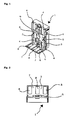
- Fig. 1 shows a perspective view of an inventive ⁇ en end cap 1 with a fastening means 2 in the form of a mounting bracket.
- the end cap 1 according to the invention can be clipped (latched) on an end face of a profile housing, not shown (eg socket profile).
- a profile housing not shown (eg socket profile).
- guides 4 are arranged, in which a tongue 5 of the fastening means 2 can be introduced, whereby the fastening means 2 is connected to the end cap 1 according to the invention.
- latching hooks 6 which engage in the inserted state of the fastening means 2 in an opening arranged on the fastening means, there is a fixation of the fastening means 2, which in Fig.
- the invention- ⁇ e end cap 1 thus has the property that a fastener 2 (eg mounting bracket, Anschraubwinkel), such as those found in IT racks use tool-free and screwless on the four outer sides can be securely locked by sliding.
- a fastener 2 eg mounting bracket, Anschraubwinkel
- the fastening system according to the invention is very space-saving to attach to the side rails of a cabinet system, with a horizontal and vertical mounting in 90 ° grid is possible.
- the arranged outside the guide 4 part 7 of an inserted into the guide 4 fastener 2 has three openings in the form of slots 8, through which the fastener 2 can be clipped to a cabinet system, screwed or otherwise fixed.
- the end cap 1 according to the invention is equipped with a hole 9.
- Fig. 2 shows a plan view of an inventive end cap 1 according to Fig. 1
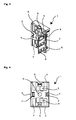
- Fig. 3 shows a perspective view of an inventive ⁇ en end cap 1 with a laterally inserted fastener 2 in the form of a mounting bracket.
- Fig. 4 shows a side view of an end cap 1 according to the invention of a socket profile (eg PDU profile, power / data supply strip) according to Fig. 3 ,
- a socket profile eg PDU profile, power / data supply strip
- Fig. 5 shows a perspective view of an inventive ⁇ en end cap 1, in which two fastening means 2 are inserted in the form of mounting brackets.
- Fig. 6 shows a side view of an end cap 1 according to the invention Fig. 5 ,
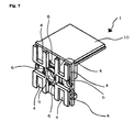
- Fig. 7 shows a perspective view of another embodiment of an end cap according to the invention 1.
- This can preferably be used in U-shaped profile housings, so that their front side closed by the provided with the hole 9 part of the end cap 1 according to the invention and the open part of the profile housing by a cover 10 becomes.
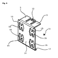
- Fig. 8 shows a perspective view of an adapter 11 in the form of an angle adapter.
- the adapter 11 has tongues 5 which are insertable into the guides 4 of the end cap 1 according to the invention.
- an opening 12 which cooperates with a latching hook 6 of the end cap 1 according to the invention, the adapter 11 is fixed in the inserted state to the end cap 1 according to the invention.
- a collar 13 causes a part 14, which is arranged outside the guide, of an adapter 11 inserted into the guide 4 to be spaced from a wall of the profile housing. This makes it possible that, for example, receiving pin of fasteners through slots 15 which are provided with insertion holes 16, are insertable.
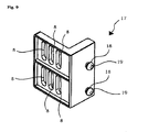
- Fig. 9 shows a perspective view of another embodiment of a fastening means 17 in the form of a mounting bracket.
- the fastening means 17 has spigot 18, whose mushroom-shaped heads 19 by the in Fig. 8 shown insertion holes 16 fit, so that then a fixation in the slots 15 is made possible.
- the fastening means 17 has elongated holes 8, by means of which the fastening means 17 can be clipped, screwed or otherwise fixed to a cabinet system.
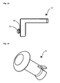
- Fig. 10 and the Fig. 11 show perspective views of yet another embodiment of a fastening means 17 in the form of a mounting bracket.
- the slots 8 can be at least partially replaced by, for example, round holes 20, so that thereby a more accurate fixation of the fastener 17 is made possible on the cabinet system.
- Fig. 12 and the Fig. 13 show a plan view and a side view of the fastener according to Fig. 10 ,
- Fig. 14 shows a perspective view of a Sp Schwarzniets 20, which can be used to fix the fastening means 2 and 17 shown in the preceding figures on a cabinet system.
- the expansion rivet 20 can be designed as Kunststoffsp Schwarzniet.
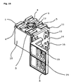
- Fig. 15 shows a perspective view of a fastening system according to the invention consisting of an inventive ⁇ en End cap 1 according to Fig. 7 , an adapter 11 according to Fig. 8 and a fastener 17 according to Fig. 9 ,
- Fig. 16 shows a different perspective view of the fastening system according to the invention according to Fig. 15 , It is clear that the necessary distance is created by the collar 13 of the adapter 11, so that the head 18 can be inserted through the insertion hole 16 for fixing the fastening means 17.
- Fig. 17 shows a perspective view of another embodiment of an end cap according to the invention 1. This can be screwed through openings 21 on the end face of a profile housing, not shown.
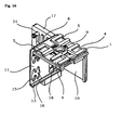
- Fig. 18 shows a perspective view of a fastening system according to the invention consisting of an inventive end cap 1 according to FIG Fig. 17 , an adapter 11 according to Fig. 8 and a fastener 17 according to Fig. 9 ,
- Fig. 19 shows a different perspective view of the fastening system according to the invention according to Fig. 18 .
Landscapes
- Engineering & Computer Science (AREA)
- Architecture (AREA)
- Civil Engineering (AREA)
- Structural Engineering (AREA)
- Casings For Electric Apparatus (AREA)
Abstract
Description
- Die Erfindung geht aus von einer Endkappe, nach der Gattung des Anspruchs 1, einem Befestigungssystem zur Befestigung eines Profilgehäuses in einem Schranksystem, nach der Gattung des Anspruchs 12, und einem Verfahren zur Befestigung eines Profilgehäuses in einem Schranksystem, nach der Gattung des Anspruchs 14.
- Bei den bestehenden zum Stand der Technik gehörenden Befestigungen von Profilgehäusen in Schranksystemen werden häufig Montagewinkel eingesetzt, die zur Verbindung mit dem Profilgehäuse mittels eines Werkzeuges mit diesem verschraubt werden. Dieser Arbeitsschritt ist zeitaufwändig. Nachteilig ist zudem, dass beim Fehlen des passenden Werkzeuges eine zufrieden stellende Verbindung nicht möglich ist.
- Um diese Nachteile zu überwinden wird in der Patentschrift
US 5,587,889 A eine Verbindung vorgeschlagen, bei der ein Gehäuse an einer Halterung mittels einer Klemme fixiert wird. Zwar handelt es sich dabei um eine schraubenlose Verbindung, doch ist nachteilig zu bewerten, dass diese schraubenlose Verbindung passgenau aufeinander abgestimmt sein muss, so dass dieses Befestigungssystem nicht universal einsetzbar ist. - Die erfindungsgemäße Endkappe, mit dem kennzeichnenden Merkmale des Anspruchs 1, das erfindungsgemäße Befestigungssystem zur Befestigung eines Profilgehäuses in einem Schranksystem, mit den kennzeichnenden Merkmalen des Anspruchs 12, und das erfindungsgemäße Verfahren zur Befestigung eines Profilgehäuses in einem Schranksystem, mit den kennzeichnenden Merkmalen des Anspruchs 14, haben demgegenüber den Vorteil, dass die Endkappe mindestens eine Führung aufweist, so dass mindestens ein Befestigungsmittel werkzeuglos an der Endkappe angeordnet werden kann, wobei das Befestigungsmittel an seiner dem Schranksystem zugewandten Seite Befestigungsmöglichkeiten vorsieht, die einen Einbau in alle herkömmlichen Schranksysteme ermöglichen.
- Nach einer vorteilhaften Ausgestaltung der erfindungsgemäßen Endkappe erfolgt die Anordnung des Befestigungsmittels an der Endkappe direkt durch Einschieben des Befestigungsmittels in die Führung der Endkappe oder indirekt mittels mindestens einen in die Führung der Endkappe einschiebbaren Adapters.
- Nach einer diesbezüglichen vorteilhaften Ausgestaltung der erfindungsgemäßen Endkappe weist die Endkappe und/oder das Befestigungsmittel mindestens einen Rasthaken auf, wodurch ein in die Führung eingeschobenes Befestigungsmittel mit der Endkappe verrastet oder weist die Endkappe und/oder der Adapter mindestens einen Rasthaken auf, wodurch ein in die Führung eingeschobener Adapter mit der Endkappe verrastet.
- Nach einer zusätzlichen vorteilhaften Ausgestaltung der erfindungsgemäßen Endkappe weist das Befestigungsmittel und/oder der Adapter mindestens einen Winkel auf. Im Falle des Befestigungsmittels handelt es sich somit um einen Befestigungswinkel (z.B. Montagewinkel). Im Falle des Adapters handelt es sich somit um einen Winkeladapter.
- Nach einer zusätzlichen vorteilhaften Ausgestaltung der erfindungsgemäßen Endkappe weist ein außerhalb der Führung angeordneter Teil eines in die Führung eingeschobenen Befestigungsmittels oder ein außerhalb der Führung angeordneter Teil eines in die Führung eingeschobenen Adapters mindestens eine Öffnung auf.
- Nach einer diesbezüglichen vorteilhaften Ausgestaltung der erfindungsgemäßen Endkappe ist die Öffnung ein Rechteckloch, Rundloch oder Langloch.
- Nach einer zusätzlichen vorteilhaften Ausgestaltung der erfindungsgemäßen Endkappe sind eine außerhalb der Führung angeordnete Fläche eines in die Führung eingeschobenen Befestigungsmittels oder eine außerhalb der Führung angeordnete Fläche eines in die Führung eingeschobenen Adapters parallel zu einer Wandung des Profilgehäuses angeordnet.
- Nach einer diesbezüglichen vorteilhaften Ausgestaltung der erfindungsgemäßen Endkappe ist die parallel zur Wandung des Profilgehäuses angeordnete Fläche beabstandet zu der Wandung des Profilgehäuses angeordnet.
- Nach einer zusätzlichen vorteilhaften Ausgestaltung der erfindungsgemäßen Endkappe weist die Endkappe ein Loch zur Kabeleinspeisung (z.B. für ein Netzkabel, Datenkabel, Multimediakabel odgl.) oder eine Aussparung für einen Stecker auf.
- Nach einer zusätzlichen vorteilhaften Ausgestaltung der erfindungsgemäßen Endkappe ist die Endkappe durch eine Verrastung mit dem Profilgehäuse verbunden.
- Nach einer zusätzlichen vorteilhaften Ausgestaltung der erfindungsgemäßen Endkappe sind die Endkappe, das Befestigungsmittel und/oder der Adapter aus Metallguss.
- Nach einer vorteilhaften Ausgestaltung des erfindungsgemäßen Befestigungssystem zur Befestigung eines Profilgehäuses in einem Schranksystem, wobei das Befestigungssystem insbesondere aus einer mit dem Profilgehäuse verbindbaren Endkappe und mindestens einem an der Endkappe anordbaren und mit dem Schranksystem verbindbaren Befestigungsmittel besteht und die Endkappe eine Führung aufweist, in die das Befestigungsmittel oder ein Adapter, an dem das Befestigungsmittel angeordnet ist, zumindest teilweise einschiebbar sind, wodurch das Profilgehäuse werkzeuglos mit dem Befestigungsmittel verbunden wird, ist die Endkappe eine Endkappe gemäß einem der Ansprüche 1 bis 11.
- Nach einer vorteilhaften Ausgestaltung des erfindungsgemäßen Verfahrens zur Befestigung eines Profilgehäuses in einem Schranksystem, wobei ein dabei verwendetes Befestigungssystem insbesondere aus einer mit dem Profilgehäuse verbindbaren Endkappe und mindestens einem an der Endkappe anordbaren und mit dem Schranksystem verbindbaren Befestigungsmittel besteht und die Endkappe eine Führung aufweist, in die das Befestigungsmittel oder ein Adapter, an dem das Befestigungsmittel angeordnet ist, zumindest teilweise eingeschoben werden, wodurch das Profilgehäuse werkzeuglos mit dem Befestigungsmittel verbunden wird, erfolgt die Verbindung der Endkappe mit dem Befestigungsmittel oder mit dem Adapter durch Verrastung.
- Nach einer zusätzlich vorteilhaften Ausgestaltung des erfindungsgemäßen Verfahrens ist die Endkappe eine Endkappe gemäß einem der Ansprüche 1 bis 11 und/oder ist das Befestigungssystem ein Befestigungssystem nach Anspruch 12 oder Anspruch 13.
- Weitere Vorteile und vorteilhafte Ausgestaltungen der Erfindung sind der nachfolgenden Beschreibung, der Zeichnung und den Ansprüchen entnehmbar.
- Ausführungsbeispiele des Gegenstandes der Erfindung sind in der Zeichnung dargestellt und werden im Folgenden näher erläutert. Es zeigen:
- Fig. 1
- eine perspektivische Darstellung einer erfindungsgemä-βen Endkappe mit einem Befestigungsmittel in Form eines Montagewinkels,
- Fig. 2
- eine Aufsicht auf eine erfindungsgemäße Endkappe gemäß
Fig. 1 , - Fig. 3
- eine perspektivische Darstellung einer erfindungsgemä-βen Endkappe mit einem seitlich eingeschobenen Befestigungsmittel in Form eines Montagewinkels,
- Fig. 4
- eine Seitenansicht einer erfindungsgemäßen Endkappe eines Steckdosenprofils gemäß
Fig. 3 , - Fig. 5
- eine perspektivische Darstellung einer erfindungsgemä-βen Endkappe, in die zwei Befestigungsmittel in Form von Montagewinkeln eingeschoben sind,
- Fig. 6
- eine Seitenansicht einer erfindungsgemäßen Endkappe gemäß
Fig. 5 , - Fig. 7
- eine perspektivische Darstellung einer anderen Ausführungsform einer erfindungsgemäßen Endkappe,
- Fig. 8
- eine perspektivische Darstellung eines Adapters in Form eines Winkeladapters,
- Fig. 9
- eine perspektivische Darstellung einer anderen Ausführungsform eines Befestigungsmittels in Form eines Befestigungswinkels,
- Fig. 10
- eine perspektivische Darstellung einer nochmals anderen Ausführungsform eines Befestigungsmittels in Form eines Befestigungswinkels,
- Fig. 11
- eine andere perspektivische Darstellung des Befestigungsmittels gemäß
Fig. 10 , - Fig. 12
- eine Aufsicht des Befestigungsmittels gemäß
Fig. 10 , - Fig. 13
- eine Seitenansicht des Befestigungsmittels gemäß
Fig. 10 , - Fig. 14
- eine perspektivische Darstellung eines Spreizniets,
- Fig. 15
- eine perspektivische Darstellung eines erfindungsgemä-βen Befestigungssystems bestehend aus einer erfindungsgemäßen Endkappe gemäß
Fig. 7 , einem Adapter gemäßFig. 8 und einem Befestigungsmittel gemäßFig. 9 , - Fig. 16
- eine andere perspektivische Darstellung des erfindungsgemäßen Befestigungssystems gemäß
Fig. 15 , - Fig. 17
- eine perspektivische Darstellung einer anderen Ausführungsform einer erfindungsgemäßen Endkappe,
- Fig. 18
- eine perspektivische Darstellung eines erfindungsgemä-βen Befestigungssystems bestehend aus einer erfindungsgemäßen Endkappe gemäß
Fig. 17 , einem Adapter gemäßFig. 8 und einem Befestigungsmittel gemäßFig. 9 und - Fig. 19
- eine andere perspektivische Darstellung des erfindungsgemäßen Befestigungssystems gemäß
Fig. 18 . -
Fig. 1 zeigt eine perspektivische Darstellung einer erfindungsgemä-βen Endkappe 1 mit einem Befestigungsmittel 2 in Form eines Montagewinkels. Die erfindungsgemäße Endkappe 1 kann an einer Stirnseite eines nicht dargestellten Profilgehäuse (z.B. Steckdosenprofil) eingeclipst (verrastet) werden. Auf einer dem Profilgehäuse abgewandten Seite 3 der erfindungsgemäßen Endkappe 1 sind Führungen 4 angeordnet, in die eine Zunge 5 des Befestigungsmittels 2 eingeführt werden können, wodurch das Befestigungsmittel 2 mit der erfindungsgemäßen Endkappe 1 verbunden wird. Mittels Rasthaken 6, die im eingeschobenen Zustand des Befestigungsmittels 2 in eine am Befestigungsmittel angeordnete Öffnung eingreifen, findet eine Fixierung des Befestigungsmittels 2, das inFig. 1 von unten in die Führung 4 der erfindungsgemäßen Endkappe 1 eingeschoben wurde, an der erfindungsgemäßen Endkappe 1 statt. Die Entnahme des Befestigungsmittels 2 erfolgt durch Niederdrücken des Rasthakens 6, wodurch das Befestigungsmittel 2 aus der erfindungsgemä-βen Endkappe 1 herausgezogen werden kann. Die erfindungsgemä-βe Endkappe 1 weist somit die Eigenschaft auf, dass ein Befestigungsmittel 2 (z.B. Montagewinkel, Anschraubwinkel), wie sie z.B. in IT Racks Verwendung finden werkzeuglos und schraubenlos an den vier Außenseiten durch Aufschieben sicher verrastet werden kann. Dadurch ist das erfindungsgemäße Befestigungssystem sehr platzsparend an den Seitenholmen eines Schranksystems zu befestigen, wobei eine horizontale und eine vertikale Anbringung im 90° Raster möglich ist. - Der außerhalb der Führung 4 angeordneter Teil 7 eines in die Führung 4 eingeschobenen Befestigungsmittels 2 weist drei Öffnungen in Form von Langlöchern 8 auf, durch die das Befestigungsmittel 2 an einem Schranksystem geclipst, verschraubt oder anderweitig fixiert werden kann.
- Im Falle, dass durch die erfindungsgemäße Endkappe 1 die Kabeleinspeisung in das Profilgehäuse erfolgen soll, ist die die erfindungsgemäße Endkappe 1 mit einem Loch 9 ausgestattet.
-
Fig. 2 zeigt eine Aufsicht auf eine erfindungsgemäße Endkappe 1 gemäßFig. 1 -
Fig. 3 zeigt eine perspektivische Darstellung einer erfindungsgemä-βen Endkappe 1 mit einem seitlich eingeschobenen Befestigungsmittel 2 in Form eines Montagewinkels. -
Fig. 4 zeigt eine Seitenansicht einer erfindungsgemäßen Endkappe 1 eines Steckdosenprofils (z.B. PDU-Profil, Power/Daten-Versorgungsleiste) gemäßFig. 3 . -
Fig. 5 zeigt eine perspektivische Darstellung einer erfindungsgemä-βen Endkappe 1, in die zwei Befestigungsmittel 2 in Form von Montagewinkeln eingeschoben sind. -
Fig. 6 zeigt eine Seitenansicht einer erfindungsgemäßen Endkappe 1 gemäßFig. 5 . -
Fig. 7 zeigt eine perspektivische Darstellung einer anderen Ausführungsform einer erfindungsgemäßen Endkappe 1. Diese kann bevorzugt bei U-förmigen Profilgehäusen eingesetzt werden, so dass deren Stirnseite durch das mit dem Loch 9 versehenen Teil der erfindungsgemäßen Endkappe 1 und der offene Teil des Profilgehäuses durch eine Abdeckung 10 verschlossen wird. -
Fig. 8 zeigt eine perspektivische Darstellung eines Adapters 11 in Form eines Winkeladapters. Der Adapter 11 weist Zungen 5 auf, die in die Führungen 4 der erfindungsgemäßen Endkappe 1 einführbar sind. Durch eine Öffnung 12, die mit einem Rasthaken 6 der erfindungsgemäßen Endkappe 1 zusammenwirkt, wird der Adapter 11 im eingeschobenen Zustand an der erfindungsgemäßen Endkappe 1 fixiert. Im eingeschobenen Zustand bewirkt ein Kragen 13, dass ein außerhalb der Führung angeordneter Teil 14 eines in die Führung 4 eingeschobenen Adapters 11 beabstandet von einer Wandung des Profilgehäuses angeordnet ist. Dadurch wird es möglich, dass z.B. Aufnahmezapfen von Befestigungsmitteln durch Langlöcher 15, die mit Einführungsbohrungen 16 versehen sind, einführbar sind. -
Fig. 9 zeigt eine perspektivische Darstellung einer anderen Ausführungsform eines Befestigungsmittels 17 in Form eines Befestigungswinkels. Das Befestigungsmittel 17 weist Aufnahmezapfen 18 auf, deren pilzförmige Köpfe 19 durch die inFig. 8 dargestellten Einführungsbohrungen 16 passen, so dass anschließend eine Fixierung in den Langlöchern 15 ermöglicht wird. Des Weiteren weist das Befestigungsmittel 17 Langlöcher 8 auf, durch die das Befestigungsmittel 17 an einem Schranksystem geclipst, verschraubt oder anderweitig fixiert werden kann. - Die
Fig. 10 und dieFig. 11 zeigen perspektivische Darstellungen einer nochmals anderen Ausführungsform eines Befestigungsmittels 17 in Form eines Befestigungswinkels. Dadurch wird deutlich, dass die Langlöcher 8 zumindest teilweise auch durch z.B. Rundlöcher 20 ersetzt werden können, so dass dadurch eine positionsgenauere Fixierung des Befestigungsmittels 17 am Schranksystem ermöglicht wird. - Die
Fig. 12 und dieFig. 13 zeigen eine Aufsicht und eine Seitenansicht des Befestigungsmittels gemäßFig. 10 . -
Fig. 14 zeigt eine perspektivische Darstellung eines Spreizniets 20, der zur Fixierung der in den vorhergehenden Figuren gezeigten Befestigungsmittel 2 und 17 an einem Schranksystem verwendet werden kann. Bevorzugt kann der Spreizniet 20 als Kunststoffspreizniet ausgestaltet sein. -
Fig. 15 zeigt eine perspektivische Darstellung eines erfindungsgemäßen Befestigungssystems bestehend aus einer erfindungsgemä-βen Endkappe 1 gemäßFig. 7 , einem Adapter 11 gemäßFig. 8 und einem Befestigungsmittel 17 gemäßFig. 9 . -
Fig. 16 zeigt eine andere perspektivische Darstellung des erfindungsgemäßen Befestigungssystems gemäßFig. 15 . Dabei wird deutlich, dass durch den Kragen 13 des Adapters 11 der notwendige Abstand geschaffen wird, damit der Kopf 18 zur Fixierung des Befestigungsmittels 17 durch die Einführungsbohrung 16 gesteckt werden kann. -
Fig. 17 zeigt eine perspektivische Darstellung einer anderen Ausführungsform einer erfindungsgemäßen Endkappe 1. Diese kann über Öffnungen 21 an der Stirnseite eines nicht dargestellten Profilgehäuses verschraubt werden. -
Fig. 18 zeigt eine perspektivische Darstellung eines erfindungsgemäßen Befestigungssystems bestehend aus einer erfindungsgemä-βen Endkappe 1 gemäßFig. 17 , einem Adapter 11 gemäßFig. 8 und einem Befestigungsmittel 17 gemäßFig. 9 . -
Fig. 19 zeigt eine andere perspektivische Darstellung des erfindungsgemäßen Befestigungssystems gemäßFig. 18 . - Alle hier dargestellten Merkmale können sowohl einzeln als auch in beliebiger Kombination miteinander erfindungswesentlich sein.
-
- 1
- Endkappe
- 2
- Befestigungsmittel
- 3
- Seite
- 4
- Führung
- 5
- Zunge
- 6
- Rasthaken
- 7
- Teil
- 8
- Langloch
- 9
- Loch
- 10
- Abdeckung
- 11
- Adapter
- 12
- Öffnung
- 13
- Kragen
- 14
- Teil
- 15
- Langloch
- 16
- Einführungsbohrung
- 17
- Befestigungsmittel
- 18
- Aufnahmezapfen
- 19
- Kopf
- 20
- Rundloch
- 21
- Spreizniet
- 22
- Öffnung
Claims (16)
- Endkappe (1) für ein in ein Schranksystem befestigbares Profilgehäuse, wobei die Befestigung des Profilgehäuses mittels eines mit der Endkappe (1) zusammenwirkenden Befestigungsmittels (2, 17) bewirkt wird,
dadurch gekennzeichnet,
dass die Endkappe (1) an ihrer dem Profilgehäuse abgewandten Seite mindestens eine Führung (4) aufweist, durch die mindestens ein Befestigungsmittel (2, 17) an der Endkappe (1) anordbar ist. - Endkappe (1), nach Anspruch 1,
dadurch gekennzeichnet,
dass die Anordnung des Befestigungsmittels (2, 17) an der Endkappe (1) direkt durch Einschieben des Befestigungsmittels (2) in die Führung (4) der Endkappe (1) oder indirekt mittels mindestens einen in die Führung (4) der Endkappe (1) einschiebbaren Adapters (11) erfolgt. - Endkappe (1), nach Anspruch 2,
dadurch gekennzeichnet,
dass die Endkappe (1) und/oder das Befestigungsmittel (2) mindestens einen Rasthaken (6) aufweist, wodurch ein in die Führung (4) eingeschobenes Befestigungsmittel (2) mit der Endkappe (1) verrastet oder die Endkappe (1) und/oder der Adapter (11) mindestens einen Rasthaken (6) aufweist, wodurch ein in die Führung (4) eingeschobener Adapter (11) mit der Endkappe (1) verrastet. - Endkappe (1), nach Anspruch 2 oder Anspruch 3,
dadurch gekennzeichnet,
dass das Befestigungsmittel (2, 17) und/oder der Adapter (11) mindestens einen Winkel aufweist. - Endkappe (1), nach einem der Ansprüche 2 bis 4,
dadurch gekennzeichnet,
dass ein außerhalb der Führung (4) angeordneter Teil (7) eines in die Führung (4) eingeschobenen Befestigungsmittels (2) oder ein außerhalb der Führung (4) angeordneter Teil (14) eines in die Führung (4) eingeschobenen Adapters (11) mindestens eine Öffnung aufweist. - Endkappe (1), nach Anspruch 5,
dadurch gekennzeichnet,
dass die Öffnung ein Rechteckloch, Rundloch oder Langloch ist. - Endkappe (1), nach einem der Ansprüche 2 bis 6,
dadurch gekennzeichnet,
dass eine außerhalb der Führung (4) angeordnete Fläche eines in die Führung (4) eingeschobenen Befestigungsmittels (2) oder eine außerhalb der Führung (4) angeordnete Fläche eines in die Führung (4) eingeschobenen Adapters (11) parallel zu einer Wandung des Profilgehäuses angeordnet sind. - Endkappe (1), nach Anspruch 7,
dadurch gekennzeichnet,
dass die parallel zur Wandung des Profilgehäuses angeordnete Fläche beabstandet zu der Wandung des Profilgehäuses angeordnet ist. - Endkappe (1), nach einem der vorhergehenden Ansprüche,
dadurch gekennzeichnet,
dass die Endkappe (1) ein Loch (9) zur Kabeleinspeisung oder eine Aussparung für einen Stecker aufweist. - Endkappe (1), nach einem der vorhergehenden Ansprüche,
dadurch gekennzeichnet,
dass die Endkappe (1) durch eine Verrastung mit dem Profilgehäuse verbunden ist. - Endkappe (1), nach einem der vorhergehenden Ansprüche,
dadurch gekennzeichnet,
dass die Endkappe (1), das Befestigungsmittel (2, 17) und/oder der Adapter (11) aus Metallguss sind. - Befestigungssystem zur Befestigung eines Profilgehäuses in einem Schranksystem, wobei das Befestigungssystem insbesondere aus einer mit dem Profilgehäuse verbindbaren Endkappe (1) und mindestens einem an der Endkappe (1) anordbaren und mit dem Schranksystem verbindbaren Befestigungsmittel (2, 17) besteht,
dadurch gekennzeichnet,
dass die Endkappe (1) eine Führung (4) aufweist, in die das Befestigungsmittel (2) oder ein Adapter (11), an dem das Befestigungsmittel (17) angeordnet ist, zumindest teilweise einschiebbar sind, wodurch das Profilgehäuse werkzeuglos mit dem Befestigungsmittel (2, 17) verbunden wird. - Befestigungssystem, nach Anspruch 12,
dadurch gekennzeichnet,
dass die Endkappe (1) eine Endkappe (1) gemäß einem der Ansprüche 1 bis 11 ist. - Verfahren zur Befestigung eines Profilgehäuses in einem Schranksystem, wobei ein dabei verwendetes Befestigungssystem insbesondere aus einer mit dem Profilgehäuse verbindbaren Endkappe (1) und mindestens einem an der Endkappe (1) anordbaren und mit dem Schranksystem verbindbaren Befestigungsmittel (2, 17) besteht,
dadurch gekennzeichnet,
dass die Endkappe (1) eine Führung (4) aufweist, in die das Befestigungsmittel (2) oder ein Adapter (11), an dem das Befestigungsmittel (17) angeordnet ist, zumindest teilweise eingeschoben werden, wodurch das Profilgehäuse werkzeuglos mit dem Befestigungsmittel (2, 17) verbunden wird. - Verfahren, nach Anspruch 14,
dadurch gekennzeichnet,
dass die Verbindung der Endkappe (1) mit dem Befestigungsmittel (2) oder mit dem Adapter (11) durch Verrastung erfolgt. - Verfahren, nach Anspruch 14 oder Anspruch 15,
dadurch gekennzeichnet,
dass die Endkappe (1) eine Endkappe (1) gemäß einem der Ansprüche 1 bis 11 ist und/oder das Befestigungssystem ein Befestigungssystem nach Anspruch 12 oder Anspruch 13 ist.
Applications Claiming Priority (1)
| Application Number | Priority Date | Filing Date | Title |
|---|---|---|---|
| DE102011122377 | 2011-12-22 |
Publications (3)
| Publication Number | Publication Date |
|---|---|
| EP2608332A2 true EP2608332A2 (de) | 2013-06-26 |
| EP2608332A3 EP2608332A3 (de) | 2014-03-05 |
| EP2608332B1 EP2608332B1 (de) | 2015-07-01 |
Family
ID=47664044
Family Applications (1)
| Application Number | Title | Priority Date | Filing Date |
|---|---|---|---|
| EP12008676.4A Active EP2608332B1 (de) | 2011-12-22 | 2012-12-21 | Endkappe; Befestigungssystem zur Befestigung eines Profilgehäuses in einem Schranksystem; Verfahren zur Befestigung eines Profilgehäuses in einem Schranksystem |
Country Status (2)
| Country | Link |
|---|---|
| EP (1) | EP2608332B1 (de) |
| DE (1) | DE102012025532A1 (de) |
Family Cites Families (4)
| Publication number | Priority date | Publication date | Assignee | Title |
|---|---|---|---|---|
| DE9104301U1 (de) * | 1991-04-09 | 1991-05-29 | Pflitsch GmbH & Co KG, 5609 Hückeswagen | Installationskanal aus Metall zum Schutz von flexiblen Langformgütern |
| US5587889A (en) | 1994-05-17 | 1996-12-24 | Palo Alto Design Group | Edge connector for securing a mountable electronic component to a device with receiving apertures for edge connector |
| FR2737055B1 (fr) * | 1995-07-19 | 1997-09-26 | Legrand Sa | Cadre pour appareillage electrique |
| DE202009009498U1 (de) * | 2009-07-11 | 2010-11-25 | Tehalit Gmbh | Klammer für Kabelkanäle zur Kaschierung von Schnittkanten |
-
2012
- 2012-12-21 EP EP12008676.4A patent/EP2608332B1/de active Active
- 2012-12-21 DE DE201210025532 patent/DE102012025532A1/de not_active Ceased
Also Published As
| Publication number | Publication date |
|---|---|
| EP2608332B1 (de) | 2015-07-01 |
| EP2608332A3 (de) | 2014-03-05 |
| DE102012025532A1 (de) | 2013-06-27 |
Similar Documents
| Publication | Publication Date | Title |
|---|---|---|
| AT16187U1 (de) | Heizvorrichtung, sowie Verfahren zur Montage einer Heizvorrichtung | |
| DE102015119976B3 (de) | Trägergestell für einen Bildschirm eines Computersystems sowie Anordnung mit einem Trägergestell | |
| DE102017108320B4 (de) | Flachteilhalter für die Befestigung eines Flachteils an einem Rahmengestell eines Schaltschranks und ein entsprechender Schaltschrank | |
| DE102012003617B4 (de) | Vorrichtung aus einem Gehäuse für ein Steuergerät und einem Befestigungselement | |
| EP3238569B1 (de) | Vorrichtung zur anbringung einer rückwand an ein bewegbares möbelteil | |
| DE202018102231U1 (de) | Montageplattenanordnung mit mehrteiligem Montageplattenhalter | |
| DE102016121074B3 (de) | Sammelschienenhalter und eine entsprechende Anordnung | |
| DE202006004081U1 (de) | Anordnung zur lösbaren Befestigung von Bauteilen an einer Decke oder Wand | |
| DE102016115404A1 (de) | System zur Festlegung wenigstens eines Wandverkleidungsteils | |
| DE102012007771C5 (de) | Montageplattenhalter für einen Schaltschrank sowie ein Befestigungsmittel zur Verwendung bei diesem | |
| DE202008005734U1 (de) | Modulares System zur Befestigung von vorzugsweise Leitungen oder Rohren in einem Flugzeug | |
| DE102011107610B4 (de) | Leitungshalter zur Befestigung an einem Träger einer Flugzeugstruktur | |
| EP2523281B1 (de) | Kabelkanal | |
| EP2608332B1 (de) | Endkappe; Befestigungssystem zur Befestigung eines Profilgehäuses in einem Schranksystem; Verfahren zur Befestigung eines Profilgehäuses in einem Schranksystem | |
| DE102016201425A1 (de) | Befestigungsvorrichtung | |
| DE29509360U1 (de) | Vorrichtung zum Befestigen eines mit einem plattenförmigen Teil versehenen Elementes an einer Wand in einem Gehäuse o.dgl. | |
| DE102024100111A1 (de) | Zähler- und Verteilerschrank | |
| DE102009056650B4 (de) | Verriegelungselement für einen Einschubserver, Einschubserver und Rackanordnung | |
| DE102007006055A1 (de) | Schaltpult | |
| DE102016107858B4 (de) | Heckblendenanordnung eines Kraftfahrzeugs | |
| EP3772788A1 (de) | Befestigungselement und befestigungssystem | |
| EP2132845B1 (de) | Schaltpult | |
| DE102017114129A1 (de) | Montageplattenanordnung für den Innenausbau eines Schaltschranks und ein entsprechender Schaltschrank | |
| WO2004109883A1 (de) | Kleinverteiler | |
| DE20104472U1 (de) | Befestigungsvorrichtung für Revisionsrahmen |
Legal Events
| Date | Code | Title | Description |
|---|---|---|---|
| AK | Designated contracting states |
Kind code of ref document: A2 Designated state(s): AL AT BE BG CH CY CZ DE DK EE ES FI FR GB GR HR HU IE IS IT LI LT LU LV MC MK MT NL NO PL PT RO RS SE SI SK SM TR |
|
| AX | Request for extension of the european patent |
Extension state: BA ME |
|
| PUAI | Public reference made under article 153(3) epc to a published international application that has entered the european phase |
Free format text: ORIGINAL CODE: 0009012 |
|
| PUAL | Search report despatched |
Free format text: ORIGINAL CODE: 0009013 |
|
| AK | Designated contracting states |
Kind code of ref document: A3 Designated state(s): AL AT BE BG CH CY CZ DE DK EE ES FI FR GB GR HR HU IE IS IT LI LT LU LV MC MK MT NL NO PL PT RO RS SE SI SK SM TR |
|
| AX | Request for extension of the european patent |
Extension state: BA ME |
|
| RIC1 | Information provided on ipc code assigned before grant |
Ipc: G11B 33/12 20060101ALI20140124BHEP Ipc: H02G 3/06 20060101AFI20140124BHEP Ipc: H02G 3/12 20060101ALI20140124BHEP Ipc: H05K 5/02 20060101ALI20140124BHEP Ipc: H02G 3/10 20060101ALI20140124BHEP |
|
| 17P | Request for examination filed |
Effective date: 20140811 |
|
| RBV | Designated contracting states (corrected) |
Designated state(s): AL AT BE BG CH CY CZ DE DK EE ES FI FR GB GR HR HU IE IS IT LI LT LU LV MC MK MT NL NO PL PT RO RS SE SI SK SM TR |
|
| GRAP | Despatch of communication of intention to grant a patent |
Free format text: ORIGINAL CODE: EPIDOSNIGR1 |
|
| INTG | Intention to grant announced |
Effective date: 20150408 |
|
| GRAS | Grant fee paid |
Free format text: ORIGINAL CODE: EPIDOSNIGR3 |
|
| GRAA | (expected) grant |
Free format text: ORIGINAL CODE: 0009210 |
|
| AK | Designated contracting states |
Kind code of ref document: B1 Designated state(s): AL AT BE BG CH CY CZ DE DK EE ES FI FR GB GR HR HU IE IS IT LI LT LU LV MC MK MT NL NO PL PT RO RS SE SI SK SM TR |
|
| REG | Reference to a national code |
Ref country code: GB Ref legal event code: FG4D Free format text: NOT ENGLISH |
|
| REG | Reference to a national code |
Ref country code: AT Ref legal event code: REF Ref document number: 734462 Country of ref document: AT Kind code of ref document: T Effective date: 20150715 Ref country code: CH Ref legal event code: EP |
|
| REG | Reference to a national code |
Ref country code: IE Ref legal event code: FG4D Free format text: LANGUAGE OF EP DOCUMENT: GERMAN |
|
| REG | Reference to a national code |
Ref country code: DE Ref legal event code: R096 Ref document number: 502012003579 Country of ref document: DE |
|
| REG | Reference to a national code |
Ref country code: SE Ref legal event code: TRGR |
|
| REG | Reference to a national code |
Ref country code: NL Ref legal event code: FP |
|
| REG | Reference to a national code |
Ref country code: NO Ref legal event code: T2 Effective date: 20150701 |
|
| REG | Reference to a national code |
Ref country code: FR Ref legal event code: PLFP Year of fee payment: 4 |
|
| REG | Reference to a national code |
Ref country code: LT Ref legal event code: MG4D |
|
| PG25 | Lapsed in a contracting state [announced via postgrant information from national office to epo] |
Ref country code: GR Free format text: LAPSE BECAUSE OF FAILURE TO SUBMIT A TRANSLATION OF THE DESCRIPTION OR TO PAY THE FEE WITHIN THE PRESCRIBED TIME-LIMIT Effective date: 20151002 Ref country code: LT Free format text: LAPSE BECAUSE OF FAILURE TO SUBMIT A TRANSLATION OF THE DESCRIPTION OR TO PAY THE FEE WITHIN THE PRESCRIBED TIME-LIMIT Effective date: 20150701 Ref country code: LV Free format text: LAPSE BECAUSE OF FAILURE TO SUBMIT A TRANSLATION OF THE DESCRIPTION OR TO PAY THE FEE WITHIN THE PRESCRIBED TIME-LIMIT Effective date: 20150701 |
|
| PG25 | Lapsed in a contracting state [announced via postgrant information from national office to epo] |
Ref country code: PT Free format text: LAPSE BECAUSE OF FAILURE TO SUBMIT A TRANSLATION OF THE DESCRIPTION OR TO PAY THE FEE WITHIN THE PRESCRIBED TIME-LIMIT Effective date: 20151102 Ref country code: PL Free format text: LAPSE BECAUSE OF FAILURE TO SUBMIT A TRANSLATION OF THE DESCRIPTION OR TO PAY THE FEE WITHIN THE PRESCRIBED TIME-LIMIT Effective date: 20150701 Ref country code: ES Free format text: LAPSE BECAUSE OF FAILURE TO SUBMIT A TRANSLATION OF THE DESCRIPTION OR TO PAY THE FEE WITHIN THE PRESCRIBED TIME-LIMIT Effective date: 20150701 Ref country code: IS Free format text: LAPSE BECAUSE OF FAILURE TO SUBMIT A TRANSLATION OF THE DESCRIPTION OR TO PAY THE FEE WITHIN THE PRESCRIBED TIME-LIMIT Effective date: 20151101 Ref country code: HR Free format text: LAPSE BECAUSE OF FAILURE TO SUBMIT A TRANSLATION OF THE DESCRIPTION OR TO PAY THE FEE WITHIN THE PRESCRIBED TIME-LIMIT Effective date: 20150701 Ref country code: RS Free format text: LAPSE BECAUSE OF FAILURE TO SUBMIT A TRANSLATION OF THE DESCRIPTION OR TO PAY THE FEE WITHIN THE PRESCRIBED TIME-LIMIT Effective date: 20150701 |
|
| REG | Reference to a national code |
Ref country code: DE Ref legal event code: R097 Ref document number: 502012003579 Country of ref document: DE |
|
| PG25 | Lapsed in a contracting state [announced via postgrant information from national office to epo] |
Ref country code: EE Free format text: LAPSE BECAUSE OF FAILURE TO SUBMIT A TRANSLATION OF THE DESCRIPTION OR TO PAY THE FEE WITHIN THE PRESCRIBED TIME-LIMIT Effective date: 20150701 Ref country code: IT Free format text: LAPSE BECAUSE OF FAILURE TO SUBMIT A TRANSLATION OF THE DESCRIPTION OR TO PAY THE FEE WITHIN THE PRESCRIBED TIME-LIMIT Effective date: 20150701 Ref country code: DK Free format text: LAPSE BECAUSE OF FAILURE TO SUBMIT A TRANSLATION OF THE DESCRIPTION OR TO PAY THE FEE WITHIN THE PRESCRIBED TIME-LIMIT Effective date: 20150701 Ref country code: CZ Free format text: LAPSE BECAUSE OF FAILURE TO SUBMIT A TRANSLATION OF THE DESCRIPTION OR TO PAY THE FEE WITHIN THE PRESCRIBED TIME-LIMIT Effective date: 20150701 Ref country code: SK Free format text: LAPSE BECAUSE OF FAILURE TO SUBMIT A TRANSLATION OF THE DESCRIPTION OR TO PAY THE FEE WITHIN THE PRESCRIBED TIME-LIMIT Effective date: 20150701 |
|
| PLBE | No opposition filed within time limit |
Free format text: ORIGINAL CODE: 0009261 |
|
| STAA | Information on the status of an ep patent application or granted ep patent |
Free format text: STATUS: NO OPPOSITION FILED WITHIN TIME LIMIT |
|
| PG25 | Lapsed in a contracting state [announced via postgrant information from national office to epo] |
Ref country code: BE Free format text: LAPSE BECAUSE OF NON-PAYMENT OF DUE FEES Effective date: 20151231 Ref country code: RO Free format text: LAPSE BECAUSE OF FAILURE TO SUBMIT A TRANSLATION OF THE DESCRIPTION OR TO PAY THE FEE WITHIN THE PRESCRIBED TIME-LIMIT Effective date: 20150701 |
|
| 26N | No opposition filed |
Effective date: 20160404 |
|
| PG25 | Lapsed in a contracting state [announced via postgrant information from national office to epo] |
Ref country code: MC Free format text: LAPSE BECAUSE OF FAILURE TO SUBMIT A TRANSLATION OF THE DESCRIPTION OR TO PAY THE FEE WITHIN THE PRESCRIBED TIME-LIMIT Effective date: 20150701 Ref country code: LU Free format text: LAPSE BECAUSE OF FAILURE TO SUBMIT A TRANSLATION OF THE DESCRIPTION OR TO PAY THE FEE WITHIN THE PRESCRIBED TIME-LIMIT Effective date: 20151221 |
|
| REG | Reference to a national code |
Ref country code: CH Ref legal event code: PL |
|
| PG25 | Lapsed in a contracting state [announced via postgrant information from national office to epo] |
Ref country code: SI Free format text: LAPSE BECAUSE OF FAILURE TO SUBMIT A TRANSLATION OF THE DESCRIPTION OR TO PAY THE FEE WITHIN THE PRESCRIBED TIME-LIMIT Effective date: 20150701 |
|
| REG | Reference to a national code |
Ref country code: IE Ref legal event code: MM4A |
|
| PG25 | Lapsed in a contracting state [announced via postgrant information from national office to epo] |
Ref country code: LI Free format text: LAPSE BECAUSE OF NON-PAYMENT OF DUE FEES Effective date: 20151231 Ref country code: CH Free format text: LAPSE BECAUSE OF NON-PAYMENT OF DUE FEES Effective date: 20151231 Ref country code: IE Free format text: LAPSE BECAUSE OF NON-PAYMENT OF DUE FEES Effective date: 20151221 |
|
| REG | Reference to a national code |
Ref country code: FR Ref legal event code: PLFP Year of fee payment: 5 |
|
| PG25 | Lapsed in a contracting state [announced via postgrant information from national office to epo] |
Ref country code: SM Free format text: LAPSE BECAUSE OF FAILURE TO SUBMIT A TRANSLATION OF THE DESCRIPTION OR TO PAY THE FEE WITHIN THE PRESCRIBED TIME-LIMIT Effective date: 20150701 Ref country code: BG Free format text: LAPSE BECAUSE OF FAILURE TO SUBMIT A TRANSLATION OF THE DESCRIPTION OR TO PAY THE FEE WITHIN THE PRESCRIBED TIME-LIMIT Effective date: 20150701 Ref country code: HU Free format text: LAPSE BECAUSE OF FAILURE TO SUBMIT A TRANSLATION OF THE DESCRIPTION OR TO PAY THE FEE WITHIN THE PRESCRIBED TIME-LIMIT; INVALID AB INITIO Effective date: 20121221 |
|
| PG25 | Lapsed in a contracting state [announced via postgrant information from national office to epo] |
Ref country code: CY Free format text: LAPSE BECAUSE OF FAILURE TO SUBMIT A TRANSLATION OF THE DESCRIPTION OR TO PAY THE FEE WITHIN THE PRESCRIBED TIME-LIMIT Effective date: 20150701 |
|
| PG25 | Lapsed in a contracting state [announced via postgrant information from national office to epo] |
Ref country code: MT Free format text: LAPSE BECAUSE OF FAILURE TO SUBMIT A TRANSLATION OF THE DESCRIPTION OR TO PAY THE FEE WITHIN THE PRESCRIBED TIME-LIMIT Effective date: 20150701 |
|
| REG | Reference to a national code |
Ref country code: FR Ref legal event code: PLFP Year of fee payment: 6 |
|
| PG25 | Lapsed in a contracting state [announced via postgrant information from national office to epo] |
Ref country code: MK Free format text: LAPSE BECAUSE OF FAILURE TO SUBMIT A TRANSLATION OF THE DESCRIPTION OR TO PAY THE FEE WITHIN THE PRESCRIBED TIME-LIMIT Effective date: 20150701 Ref country code: TR Free format text: LAPSE BECAUSE OF FAILURE TO SUBMIT A TRANSLATION OF THE DESCRIPTION OR TO PAY THE FEE WITHIN THE PRESCRIBED TIME-LIMIT Effective date: 20150701 |
|
| PG25 | Lapsed in a contracting state [announced via postgrant information from national office to epo] |
Ref country code: AL Free format text: LAPSE BECAUSE OF FAILURE TO SUBMIT A TRANSLATION OF THE DESCRIPTION OR TO PAY THE FEE WITHIN THE PRESCRIBED TIME-LIMIT Effective date: 20150701 |
|
| REG | Reference to a national code |
Ref country code: AT Ref legal event code: MM01 Ref document number: 734462 Country of ref document: AT Kind code of ref document: T Effective date: 20171221 |
|
| PG25 | Lapsed in a contracting state [announced via postgrant information from national office to epo] |
Ref country code: AT Free format text: LAPSE BECAUSE OF NON-PAYMENT OF DUE FEES Effective date: 20171221 |
|
| REG | Reference to a national code |
Ref country code: DE Ref legal event code: R081 Ref document number: 502012003579 Country of ref document: DE Owner name: BACHMANN GMBH, DE Free format text: FORMER OWNER: BACHMANN TECHNOLOGY GMBH & CO. KG, 70565 STUTTGART, DE |
|
| REG | Reference to a national code |
Ref country code: NO Ref legal event code: CHAD Owner name: BACHMANN GMBH, DE |
|
| REG | Reference to a national code |
Ref country code: NL Ref legal event code: PD Owner name: BACHMANN GMBH; DE Free format text: DETAILS ASSIGNMENT: CHANGE OF OWNER(S), CHANGE OF LEGAL ENTITY; FORMER OWNER NAME: BACHMANN TECHNOLOGY GMBH & CO. KG Effective date: 20220519 Ref country code: GB Ref legal event code: 732E Free format text: REGISTERED BETWEEN 20220428 AND 20220504 |
|
| REG | Reference to a national code |
Ref country code: FI Ref legal event code: PCE Owner name: BACHMANN GMBH |
|
| PGFP | Annual fee paid to national office [announced via postgrant information from national office to epo] |
Ref country code: DE Payment date: 20251210 Year of fee payment: 14 |
|
| PGFP | Annual fee paid to national office [announced via postgrant information from national office to epo] |
Ref country code: GB Payment date: 20251218 Year of fee payment: 14 |
|
| PGFP | Annual fee paid to national office [announced via postgrant information from national office to epo] |
Ref country code: NO Payment date: 20251216 Year of fee payment: 14 |
|
| PGFP | Annual fee paid to national office [announced via postgrant information from national office to epo] |
Ref country code: FI Payment date: 20251216 Year of fee payment: 14 |
|
| PGFP | Annual fee paid to national office [announced via postgrant information from national office to epo] |
Ref country code: FR Payment date: 20251217 Year of fee payment: 14 Ref country code: NL Payment date: 20251217 Year of fee payment: 14 |
|
| PGFP | Annual fee paid to national office [announced via postgrant information from national office to epo] |
Ref country code: SE Payment date: 20251217 Year of fee payment: 14 |