EP2607525A1 - Verfahren und Vorrichtung zur Herstellung eines Einkristalls - Google Patents
Verfahren und Vorrichtung zur Herstellung eines Einkristalls Download PDFInfo
- Publication number
- EP2607525A1 EP2607525A1 EP12196076.9A EP12196076A EP2607525A1 EP 2607525 A1 EP2607525 A1 EP 2607525A1 EP 12196076 A EP12196076 A EP 12196076A EP 2607525 A1 EP2607525 A1 EP 2607525A1
- Authority
- EP
- European Patent Office
- Prior art keywords
- single crystal
- zone
- crystallization
- triple point
- distance
- Prior art date
- Legal status (The legal status is an assumption and is not a legal conclusion. Google has not performed a legal analysis and makes no representation as to the accuracy of the status listed.)
- Granted
Links
Images
Classifications
-
- C—CHEMISTRY; METALLURGY
- C30—CRYSTAL GROWTH
- C30B—SINGLE-CRYSTAL GROWTH; UNIDIRECTIONAL SOLIDIFICATION OF EUTECTIC MATERIAL OR UNIDIRECTIONAL DEMIXING OF EUTECTOID MATERIAL; REFINING BY ZONE-MELTING OF MATERIAL; PRODUCTION OF A HOMOGENEOUS POLYCRYSTALLINE MATERIAL WITH DEFINED STRUCTURE; SINGLE CRYSTALS OR HOMOGENEOUS POLYCRYSTALLINE MATERIAL WITH DEFINED STRUCTURE; AFTER-TREATMENT OF SINGLE CRYSTALS OR A HOMOGENEOUS POLYCRYSTALLINE MATERIAL WITH DEFINED STRUCTURE; APPARATUS THEREFOR
- C30B13/00—Single-crystal growth by zone-melting; Refining by zone-melting
- C30B13/16—Heating of the molten zone
- C30B13/20—Heating of the molten zone by induction, e.g. hot wire technique
-
- C—CHEMISTRY; METALLURGY
- C30—CRYSTAL GROWTH
- C30B—SINGLE-CRYSTAL GROWTH; UNIDIRECTIONAL SOLIDIFICATION OF EUTECTIC MATERIAL OR UNIDIRECTIONAL DEMIXING OF EUTECTOID MATERIAL; REFINING BY ZONE-MELTING OF MATERIAL; PRODUCTION OF A HOMOGENEOUS POLYCRYSTALLINE MATERIAL WITH DEFINED STRUCTURE; SINGLE CRYSTALS OR HOMOGENEOUS POLYCRYSTALLINE MATERIAL WITH DEFINED STRUCTURE; AFTER-TREATMENT OF SINGLE CRYSTALS OR A HOMOGENEOUS POLYCRYSTALLINE MATERIAL WITH DEFINED STRUCTURE; APPARATUS THEREFOR
- C30B9/00—Single-crystal growth from melt solutions using molten solvents
-
- C—CHEMISTRY; METALLURGY
- C30—CRYSTAL GROWTH
- C30B—SINGLE-CRYSTAL GROWTH; UNIDIRECTIONAL SOLIDIFICATION OF EUTECTIC MATERIAL OR UNIDIRECTIONAL DEMIXING OF EUTECTOID MATERIAL; REFINING BY ZONE-MELTING OF MATERIAL; PRODUCTION OF A HOMOGENEOUS POLYCRYSTALLINE MATERIAL WITH DEFINED STRUCTURE; SINGLE CRYSTALS OR HOMOGENEOUS POLYCRYSTALLINE MATERIAL WITH DEFINED STRUCTURE; AFTER-TREATMENT OF SINGLE CRYSTALS OR A HOMOGENEOUS POLYCRYSTALLINE MATERIAL WITH DEFINED STRUCTURE; APPARATUS THEREFOR
- C30B11/00—Single-crystal growth by normal freezing or freezing under temperature gradient, e.g. Bridgman-Stockbarger method
-
- C—CHEMISTRY; METALLURGY
- C30—CRYSTAL GROWTH
- C30B—SINGLE-CRYSTAL GROWTH; UNIDIRECTIONAL SOLIDIFICATION OF EUTECTIC MATERIAL OR UNIDIRECTIONAL DEMIXING OF EUTECTOID MATERIAL; REFINING BY ZONE-MELTING OF MATERIAL; PRODUCTION OF A HOMOGENEOUS POLYCRYSTALLINE MATERIAL WITH DEFINED STRUCTURE; SINGLE CRYSTALS OR HOMOGENEOUS POLYCRYSTALLINE MATERIAL WITH DEFINED STRUCTURE; AFTER-TREATMENT OF SINGLE CRYSTALS OR A HOMOGENEOUS POLYCRYSTALLINE MATERIAL WITH DEFINED STRUCTURE; APPARATUS THEREFOR
- C30B13/00—Single-crystal growth by zone-melting; Refining by zone-melting
- C30B13/28—Controlling or regulating
- C30B13/30—Stabilisation or shape controlling of the molten zone, e.g. by concentrators, by electromagnetic fields; Controlling the section of the crystal
-
- C—CHEMISTRY; METALLURGY
- C30—CRYSTAL GROWTH
- C30B—SINGLE-CRYSTAL GROWTH; UNIDIRECTIONAL SOLIDIFICATION OF EUTECTIC MATERIAL OR UNIDIRECTIONAL DEMIXING OF EUTECTOID MATERIAL; REFINING BY ZONE-MELTING OF MATERIAL; PRODUCTION OF A HOMOGENEOUS POLYCRYSTALLINE MATERIAL WITH DEFINED STRUCTURE; SINGLE CRYSTALS OR HOMOGENEOUS POLYCRYSTALLINE MATERIAL WITH DEFINED STRUCTURE; AFTER-TREATMENT OF SINGLE CRYSTALS OR A HOMOGENEOUS POLYCRYSTALLINE MATERIAL WITH DEFINED STRUCTURE; APPARATUS THEREFOR
- C30B29/00—Single crystals or homogeneous polycrystalline material with defined structure characterised by the material or by their shape
- C30B29/02—Elements
- C30B29/06—Silicon
-
- Y—GENERAL TAGGING OF NEW TECHNOLOGICAL DEVELOPMENTS; GENERAL TAGGING OF CROSS-SECTIONAL TECHNOLOGIES SPANNING OVER SEVERAL SECTIONS OF THE IPC; TECHNICAL SUBJECTS COVERED BY FORMER USPC CROSS-REFERENCE ART COLLECTIONS [XRACs] AND DIGESTS
- Y10—TECHNICAL SUBJECTS COVERED BY FORMER USPC
- Y10T—TECHNICAL SUBJECTS COVERED BY FORMER US CLASSIFICATION
- Y10T117/00—Single-crystal, oriented-crystal, and epitaxy growth processes; non-coating apparatus therefor
- Y10T117/10—Apparatus
- Y10T117/1024—Apparatus for crystallization from liquid or supercritical state
- Y10T117/1076—Apparatus for crystallization from liquid or supercritical state having means for producing a moving solid-liquid-solid zone
- Y10T117/1088—Apparatus for crystallization from liquid or supercritical state having means for producing a moving solid-liquid-solid zone including heating or cooling details
Definitions
- the invention relates to a method for producing a single crystal by zoning and a device which is suitable for use of the method.
- zoning is used in particular for the production of single crystals of silicon.
- polycrystalline silicon is inductively melted and crystallized on a monocrystalline seed crystal.
- the polycrystalline silicon is usually provided in the form of a stock rod which is gradually melted from its lower end by means of an induction heating coil, with a molten silicon melting zone forming the growth of the single crystal. This method is called FZ method below.
- a variant of the FZ process which is referred to below as GFZ process, uses polycrystalline granules of silicon ("granular silicon") instead of a stock rod. While an induction heating coil is used in the FZ process for melting the stock rod and for controlled crystallization of the single crystal, two induction heating coils are used in the GFZ process.
- the polycrystalline granules are melted by means of a first induction heating coil on a plate and then flows through a hole in the center of the plate to the growing single crystal and forms a melting zone.
- the crystallization of the single crystal is controlled by means of a second induction heating coil located below the first induction heating coil. Further details on the GFZ process are for example in the US 2011/0095018 A1 described.
- Object of the present invention is therefore to counteract the deflection of the crystallization boundary and the load of the single crystal by thermal stresses in a more advantageous manner.
- the object is achieved by a method for producing a single crystal by zone pulling, wherein the single crystal crystallizes with the assistance of an induction heating coil under a melting zone at a crystallization boundary, and the radiation of heat of crystallization is hindered by a reflector surrounding the single crystal, characterized in that the single crystal in Area of an outer edge of the crystallization boundary is heated by means of a heater in a first zone, wherein a distance ⁇ between an outer triple point T a at the outer edge of the crystallization boundary and a center Z of the crystallization boundary is affected.
- a device for producing a single crystal by zone pulling comprising a reflector surrounding the single crystal and a heater for heating the single crystal in the region of an outer edge of a crystallization boundary of the single crystal.
- the present invention aims to increase the temperature in the region of the upper end of the single crystal from the side so that the axial position of the crystallization boundary is influenced at the periphery of the single crystal, such that the deflection of the crystallization boundary, ie the vertical distance between the center and the edge of the crystallization boundary is limited.
- the present invention can be applied regardless of whether silicon or other semiconductor material is crystallized and irrespective of whether crystallization is by the FZ or GFZ method.
- the single crystal is heated by means of a radiant heater, which is arranged around the upper end of the growing single crystal.
- the radiant heater can emit, for example, IR or optical radiation. Particularly preferred is the use of a halogen radiant heater.
- induction heating or resistance heating or other heating means may be used to transmit heat to the region of the outer edge of the crystallization boundary.
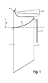
- the monocrystal 1 grows at a crystallization boundary 2 between the monocrystal and a molten zone 3 of molten material and is thereby lowered (FIG. Fig.1 ).
- the molten material is preferably derived from a polycrystalline silicon stockpile or polycrystalline silicon pellets.
- the melting zone 3 is heated by means of a high-frequency induction heating coil (HF inductor) 4. Crystallization heat arising during growth of the single crystal is passed through the single crystal and emitted in particular via the shell 5 of the single crystal.
- the result of the heat transport is that, in particular in the region of the crystallization boundary 2, an inhomogeneous temperature field arises, which is responsible for the deflection of the crystallization boundary 2 to the monocrystal.
- the deflection of the crystallization boundary is defined as the axial distance ⁇ between an outer triple point T a at the outer edge of the crystallization boundary and the center Z of the crystallization boundary 2.
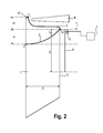
- the present invention further provides for heating the single crystal in the region of an outer edge of the crystallization boundary by means of a heating device 6, and in this way influencing the distance ⁇ between the outer triple point T a at the outer edge of the crystallization boundary and the center Z of the crystallization boundary 2 ( Fig.2 ).
- the heater 6 is disposed in the immediate vicinity of the single crystal, and the single crystal is directly heated by the heater 6.
- energy is supplied to the monocrystal with an electric power of preferably not less than 2 kW and not more than 12 kW, more preferably not less than 4 kW and not more than 10 kW.
- the upper limit of this range is based on a single crystal having a diameter of 150 mm. If a single crystal is to be manufactured with a larger diameter, the upper limit of this range is higher by a factor corresponding to the ratio of the diameters.
- the single crystal is preferably heated with the aid of the heating device such that the distance ⁇ between the outer triple point T a at the outer edge of the crystallization boundary and the center Z of the crystallization boundary 2 is not more than 90% of the distance ⁇ 'and more preferably not more than 80 %.
- the distance ⁇ ' is the distance between the outer triple point T a and the center Z, which exists if the heater 6 is dispensed with.
- a controller 7 which influences the electric power of the heater, for example, a controller that reduces the electric power of the heater with increasing length of the single crystal.
- the distance H in the melting zone corresponds to the distance between an inner triple point T i at the top End of the melting zone and the outer triple point T a at the outer edge of the crystallization boundary.
- the area of the single crystal heated by the heater 6 corresponds to a first zone having a length L in the longitudinal direction of the single crystal.
- the length L which runs parallel to the geometric axis A (longitudinal axis) of the monocrystal from the outer triple point T a , should not be longer than the distance ⁇ and preferably not longer than ⁇ / 2.
- the distance ⁇ is the distance between the outer triple point T a at the outer edge of the crystallization boundary and the center Z of the crystallization boundary, which results when using the invention. If the heating device 6 also heated a region below said region, although thermal stresses could be reduced, the deflection would increase.
- the reflector should be dimensioned so that it hinders the emission of heat of crystallization in a second zone, so that in its sphere of influence, the radial temperature distribution in the single crystal is made uniform.
- the second zone joins the first zone. It has a length S in the longitudinal direction of the single crystal, wherein the sum of the lengths S and L preferably corresponds to 0.5 to 1.5 times the length of the diameter D of the single crystal.
- the reflectance of the single crystal-directed inner wall of the reflector is preferably not less than 80%.
- the reflector 8 is preferably made entirely of silver or has at least one inner wall made of silver.
- the inner wall is preferably polished.
- the heating device 6 is preferably arranged directly above the reflector 8. But you can also go to the top be integrated with the reflector 8. If this is not the case, the heating device 6 and the reflector 8 can be mechanically connected or arranged separately from one another. By the latter, the heat conduction to the reflector can be effectively restricted.
- the heater 6 is made of high temperature resistant material with high reflectance and preferably designed as a radiant heater. Particularly preferred is a radiant heater, which comprises one or more halogen lamps, in particular a radiant heater, which is formed by a ring of halogen lamps, which surrounds the single crystal in the region of the outer edge of the crystallization boundary.
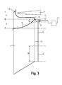
- the device according to the invention differs from that in FIG Fig.2 essentially by an additional feature, namely a surrounding the single crystal and heat radiation receiving body 9.
- This body may be a passive heat sink or an active cooling device. It facilitates the radiating of heat of crystallization by the single crystal in a third zone following the second zone.
- the third zone has the length W and starts at a distance from the outer triple point T a , which has at least the length of the diameter D of the single crystal.
- the length W of the third zone is preferably not shorter than half the diameter of the single crystal.
- the body 9 has a reflectance of preferably not more than 20%. It is connected to the reflector 8 via a heat-insulating bridge or mounted without touching the reflector.
Landscapes
- Chemical & Material Sciences (AREA)
- Engineering & Computer Science (AREA)
- Crystallography & Structural Chemistry (AREA)
- Materials Engineering (AREA)
- Metallurgy (AREA)
- Organic Chemistry (AREA)
- Physics & Mathematics (AREA)
- Electromagnetism (AREA)
- Crystals, And After-Treatments Of Crystals (AREA)
- Liquid Deposition Of Substances Of Which Semiconductor Devices Are Composed (AREA)
Abstract
Description
- Gegenstand der Erfindung ist ein Verfahren zur Herstellung eines Einkristalls durch Zonenziehen und eine Vorrichtung, die zur Anwendung des Verfahrens geeignet ist.
- In industriellem Maßstab wird das Zonenziehen insbesondere zur Herstellung von Einkristallen aus Silizium eingesetzt. Hierzu wird polykristallines Silizium induktiv geschmolzen und auf einem einkristallinen Keimkristall kristallisiert. Das polykristalline Silizium wird üblicherweise in Form eines Vorratsstabs bereitgestellt, der mittels einer Induktionsheizspule von seinem unteren Ende an beginnend nach und nach geschmolzen wird, wobei eine sich bildende Schmelzenzone aus geschmolzenem Silizium dem Wachstum des Einkristalls dient. Dieses Verfahren wird nachfolgend FZ-Verfahren genannt.
- Eine Variante des FZ-Verfahrens, die nachfolgend GFZ-Verfahren genannt wird, verwendet an Stelle eines Vorratsstabs polykristallines Granulat aus Silizium ("granular silicon"). Während beim FZ-Verfahren eine Induktionsheizspule zum Schmelzen des Vorratsstabs und zum kontrollierten Kristallisieren des Einkristalls verwendet wird, kommen beim GFZ-Verfahren zwei Induktionsheizspulen zum Einsatz. Das polykristalline Granulat wird mit Hilfe einer ersten Induktionsheizspule auf einem Teller geschmolzen und fließt anschließend durch ein Loch im Zentrum des Tellers zum wachsenden Einkristall und bildet eine Schmelzenzone. Die Kristallisation des Einkristalls wird mit Hilfe einer zweiten Induktionsheizspule kontrolliert, die unter der ersten Induktionsheizspule angeordnet ist. Weitere Einzelheiten zum GFZ-Verfahren sind beispielsweise in der
US 2011/0095018 A1 beschrieben. - In der
DE 30 07 377 A1 sind das FZ-Verfahren und eine zu dessen Durchführung geeignete Vorrichtung beschrieben, wobei sich die Beschreibung der Aufgabe widmet, das Auftreten von Wärmespannungen zu verhindern. Zur Lösung der Aufgabe wird vorgeschlagen, den Einkristall durch Wärmestrahlung eines den Einkristall umgebenden reflektierenden Schutzmantels nachzuheizen. In der Publikation von A.Muiznieks et al. (Journal of Crystal Growth 230(2001), 305-313) wird die Wirksamkeit eines dort als Reflektor bezeichneten Schutzmantels zum Abbau von Wärmespannungen bestätigt. Simulationsrechnungen zeigen auch, dass die Wärmespannungen im Zentrum der Kristallisationsgrenze am größten sind und dass ihr Beitrag mit dem Durchmesser des Einkristalls ansteigt. Darüber hinaus wird gezeigt, dass Wärmespannungen insbesondere im Zentrum der Kristallisationsgrenze umso größer sind, je stärker die Kristallisationsgrenze zum Einkristall hin durchgebogen ist, und dass die Durchbiegung mit der Kristallisations-Geschwindigkeit des Einkristalls ansteigt. - Es besteht daher eine Notwendigkeit an Maßnahmen, die gegen die Durchbiegung der Kristallisationsgrenze gerichtet sind, ohne die Kristallisations-Geschwindigkeit einschränken zu müssen, und die geeignet sind, Wärmespannungen und die davon ausgehende Gefahr der Bildung von Versetzungen ohne Produktivitätseinbuße einzudämmen.
- Da ein den Einkristall umgebender Reflektor den Wärmetransport über den Mantel des Einkristalls behindert, muss der Schmelzenzone weniger Wärme über die Induktionsheizspule zugeführt werden, um eine Höhe der Schmelzenzone zu gewährleisten, die für das Kristallwachstum benötigt wird. Dies ist ein weiterer Vorteil, der mit dem Einsatz eines Reflektors verknüpft ist.
- Mit steigendem Durchmesser des Einkristalls und steigender Kristallisations-Geschwindigkeit nimmt die Durchbiegung der Kristallisationsgrenze zu. Damit verschärfen sich die Probleme aufgrund von Wärmespannungen. Als Gegenmaßnahme reicht der Einsatz eines Reflektors dann nicht mehr aus.
- Aufgabe der vorliegenden Erfindung ist es daher, der Durchbiegung der Kristallisationsgrenze und der Belastung des Einkristalls durch Wärmespannungen auf vorteilhaftere Weise entgegenzuwirken.
- Die Aufgabe wird gelöst durch ein Verfahren zur Herstellung eines Einkristalls durch Zonenziehen, wobei der Einkristall mit Unterstützung einer Induktionsheizspule unter einer Schmelzenzone an einer Kristallisationsgrenze kristallisiert, und das Abstrahlen von Kristallisationswärme durch einen den Einkristall umgebenden Reflektor behindert wird, dadurch gekennzeichnet, dass der Einkristall im Bereich eines äußeren Rands der Kristallisationsgrenze mittels einer Heizeinrichtung in einer ersten Zone erhitzt wird, wobei ein Abstand Δ zwischen einem äußeren Tripelpunkt Ta am äußeren Rand der Kristallisationsgrenze und einem Zentrum Z der Kristallisationsgrenze beeinflusst wird.
- Die Aufgabe wird gleichermaßen gelöst durch eine Vorrichtung zur Herstellung eines Einkristalls durch Zonenziehen, umfassend einen den Einkristall umgebenden Reflektor und eine Heizeinrichtung zum Erhitzen des Einkristalls im Bereich eines äußeren Rands einer Kristallisationsgrenze des Einkristalls.
- Die vorliegende Erfindung verfolgt das Ziel, die Temperatur im Bereich des oberen Endes des Einkristalls von der Seite so zu erhöhen, dass die axiale Lage der Kristallisationsgrenze am Umfang des Einkristalls beeinflusst wird, und zwar derart, dass die Durchbiegung der Kristallisationsgrenze, also der vertikale Abstand zwischen dem Zentrum und dem Rand der Kristallisationsgrenze begrenzt wird.
- Die vorliegende Erfindung kann unabhängig davon angewendet werden, ob Silizium oder ein anderes Halbleitermaterial kristallisiert wird und unabhängig davon, ob die Kristallisation nach dem FZ- oder dem GFZ-Verfahren geschieht.
- Gemäß einer bevorzugten Ausführungsform der Erfindung wird der Einkristall mittels einer Strahlungsheizung erhitzt, die um das obere Ende des wachsenden Einkristalls angeordnet ist. Die Strahlungsheizung kann beispielsweise IR- oder optische Strahlung emittieren. Besonders bevorzugt ist die Verwendung einer Halogen-Strahlungsheizung.
- Als Alternative kann an Stelle einer Strahlungsheizung auch eine Induktionsheizung oder eine Widerstandsheizung oder eine andere Heizeinrichtung verwendet werden, durch die Wärme in den Bereich des äußeren Rands der Kristallisationsgrenze übertragen werden kann.
- Die Erfindung wird nachfolgend anhand von Figuren eingehender beschrieben.
-
Fig.1 ist eine Schnittzeichnung, die den Stand der Technik repräsentiert und eine Hälfte eines Längsschnitts durch einen Einkristall zeigt, der gemäß dem Zonenziehen hergestellt wurde. Neben dem Einkristall sind eine Induktionsheizspule zur Kontrolle der Kristallisation des Einkristalls dargestellt sowie ein den Einkristall umgebender Reflektor, der vom Einkristall abgestrahlte Wärmestrahlung reflektiert. -
Fig.2 ist eine die Erfindung repräsentierende Schnittzeichnung. -
Fig.3 ist eine weitere, die Erfindung repräsentierende Schnittzeichnung, in der ein zusätzliches bevorzugtes Merkmal gezeigt ist. - Der Einkristall 1 wächst an einer Kristallisationsgrenze 2 zwischen dem Einkristall und einer Schmelzenzone 3 aus geschmolzenem Material und wird dabei abgesenkt (
Fig.1 ). Das geschmolzene Material stammt vorzugsweise von einem Vorratsstab aus polykristallinem Silizium oder von Granulat aus polykristallinem Silizium. Die Schmelzenzone 3 wird mit Hilfe einer Hochfrequenz-Induktionsheizspule (HF-Induktor) 4 erhitzt. Beim Wachsen des Einkristalls entstehende Kristallisationswärme wird durch den Einkristall geleitet und insbesondere über den Mantel 5 des Einkristalls abgestrahlt. Der Wärmetransport hat zur Folge, dass insbesondere im Bereich der Kristallisationsgrenze 2 ein inhomogenes Temperaturfeld entsteht, das für die Durchbiegung der Kristallisationsgrenze 2 zum Einkristall verantwortlich ist. Die Durchbiegung der Kristallisationsgrenze ist definiert als der axiale Abstand Δ zwischen einem äußeren Tripelpunkt Ta am äußeren Rand der Kristallisationsgrenze und dem Zentrum Z der Kristallisationsgrenze 2. - Mit Hilfe eines den Einkristall umgebenden Reflektors 8, der vom Einkristall 1 abgestrahlte Wärmestrahlung reflektiert, wird insbesondere die Lage des Zentrums Z der Kristallisationsgrenze 2 auf der geometrischen Achse A beeinflusst.
- Die vorliegende Erfindung sieht darüber hinaus vor, den Einkristall im Bereich eines äußeren Rands der Kristallisationsgrenze mittels einer Heizeinrichtung 6 zu erhitzen, und auf diese Weise den Abstand Δ zwischen dem äußeren Tripelpunkt Ta am äußeren Rand der Kristallisationsgrenze und Zentrum Z der Kristallisationsgrenze 2 zu beeinflussen (
Fig.2 ). - Die Heizeinrichtung 6 ist in unmittelbarer Nachbarschaft des Einkristalls angeordnet, und der Einkristall wird durch die Heizeinrichtung 6 direkt erhitzt.
- Mit Hilfe der Heizeinrichtung 6 wird dem Einkristall Energie mit einer elektrischen Leistung von vorzugsweise nicht weniger als 2 kW und nicht mehr als 12 kW, besonders bevorzugt von nicht weniger als 4 kW und nicht mehr als 10kW zugeführt. Die obere Grenze dieses Bereichs ist auf einen Einkristall mit einem Durchmesser von 150 mm bezogen. Soll ein Einkristall mit einem größeren Durchmesser hergestellt werden, ist die obere Grenze dieses Bereichs um einen Faktor entsprechend dem Verhältnis der Durchmesser höher.
- Der Einkristall wird mit Hilfe der Heizeinrichtung vorzugsweise derart erhitzt, dass der Abstand Δ zwischen dem äußeren Tripelpunkt Ta am äußeren Rand der Kristallisationsgrenze und dem Zentrum Z der Kristallisationsgrenze 2 nicht mehr als 90 % vom Abstand Δ' ist und besonders bevorzugt nicht mehr als 80 %. Der Abstand Δ' ist der Abstand zwischen dem äußeren Tripelpunkt Ta und dem Zentrum Z, der besteht, falls auf die Heizeinrichtung 6 verzichtet wird.
- Es ist bevorzugt, die elektrische Leistung der Heizeinrichtung 6 in Abhängigkeit der Länge des Einkristalls zu steuern. Zu diesem Zweck ist eine Steuerung 7 vorgesehen, die auf die elektrische Leistung der Heizeinrichtung Einfluss nimmt, beispielsweise eine Steuerung, die die elektrische Leistung der Heizeinrichtung mit zunehmender Länge des Einkristalls herabsetzt.
- Es ist darüber hinaus bevorzugt, die elektrische Leistung der Induktionsheizspule und gegebenenfalls zusätzlich die Geschwindigkeit des Absenkens des Einkristalls während des Verfahrens derart zu regeln, dass sich ein gewählter Betrag des Abstands H in der Schmelzenzone nicht verändert, beispielsweise indem der Abstand 1 zwischen dem äußeren Rand der Kristallisationsgrenze und der Hochfrequenz-Induktionsheizspule möglichst konstant gehalten wird. Der Abstand H in der Schmelzenzone entspricht dem Abstand zwischen einem inneren Tripelpunkt Ti am oberen Ende der Schmelzenzone und dem äußeren Tripelpunkt Ta am äußeren Rand der Kristallisationsgrenze.
- Der mit Hilfe der Heizeinrichtung 6 erhitzte Bereich des Einkristalls entspricht einer ersten Zone, die in Längsrichtung des Einkristalls eine Länge L hat. Die Länge L, die vom äußeren Tripelpunkt Ta ausgehend parallel zur geometrischen Achse A (Längsachse) des Einkristalls verläuft, sollte nicht länger als der Abstand Δ und vorzugsweise nicht länger als Δ/2 sein. Der Abstand Δ ist der Abstand zwischen dem äußeren Tripelpunkt Ta am äußeren Rand der Kristallisationsgrenze und dem Zentrum Z der Kristallisationsgrenze, der sich bei Benutzung der Erfindung ergibt. Würde die Heizeinrichtung 6 auch einen Bereich unter dem genannten Bereich erhitzen, könnten damit zwar Wärmespannungen verringert werden, die Durchbiegung würde sich jedoch erhöhen. Außerdem stünde eine übermäßige Behinderung des Abflusses von Wärme vom Einkristall durch die Heizeinrichtung 6 einer wirtschaftlichen Kristallisations-Geschwindigkeit entgegen. Aus demselben Grund ist es bevorzugt, die axiale Länge des Reflektors 8 zu begrenzen. Der Reflektor sollte so dimensioniert sein, dass er das Abstrahlen von Kristallisationswärme in einer zweiten Zone behindert, so dass in seinem Einflussbereich die radiale Temperaturverteilung im Einkristall vergleichmäßigt wird. Die zweite Zone schließt sich an die erste Zone an. Sie hat eine Länge S in Längsrichtung des Einkristalls, wobei die Summe der Längen S und L vorzugsweise dem 0,5 bis 1,5-Fachen der Länge des Durchmessers D des Einkristalls entspricht. Der Reflexionsgrad der zum Einkristall gerichteten Innenwand des Reflektors beträgt vorzugsweise nicht weniger als 80 %. Der Reflektor 8 besteht vorzugsweise vollständig aus Silber oder hat zumindest eine Innenwand, die aus Silber besteht. Die Innenwand ist vorzugsweise poliert.
- Die Heizeinrichtung 6 ist vorzugsweise unmittelbar über dem Reflektor 8 angeordnet. Sie kann aber auch in das obere Ende des Reflektors 8 integriert sein. Ist das nicht der Fall, können die Heizeinrichtung 6 und der Reflektor 8 mechanisch verbunden oder voneinander getrennt angeordnet sein. Durch das Letztere kann die Wärmeleitung zum Reflektor wirksam eingeschränkt werden. Die Heizeinrichtung 6 ist aus hochtemperaturbeständigem Material mit hohem Reflexionsgrad gefertigt und vorzugsweise als Strahlungsheizung ausgeführt. Besonders bevorzugt ist eine Strahlungsheizung, die eine oder mehrere Halogenlampen umfasst, insbesondere eine Strahlungsheizung, die von einem Ring aus Halogenlampen gebildet wird, der den Einkristall im Bereich des äußeren Rands der Kristallisationsgrenze umgibt.
- Die in
Fig.3 gezeigte erfindungsgemäße Vorrichtung unterscheidet sich von der inFig.2 gezeigten Vorrichtung im Wesentlichen durch ein zusätzliches Merkmal, nämlich einen den Einkristall umgebenden und Wärmestrahlung aufnehmenden Körper 9. Dieser Körper kann ein passiver Kühlkörper oder eine aktive Kühleinrichtung sein. Er erleichtert das Abstrahlen von Kristallisationswärme durch den Einkristall in einer dritten Zone, die der zweiten Zone folgt. Die dritte Zone hat die Länge W und beginnt in einem Abstand vom äußeren Tripelpunkt Ta, der mindestens die Länge des Durchmessers D des Einkristalls hat. Die Länge W der dritten Zone ist vorzugsweise nicht kürzer als die Hälfte des Durchmessers des Einkristalls. Der Körper 9 hat einen Reflexionsgrad von vorzugsweise nicht mehr als 20%. Er ist über eine wärmeisolierende Brücke mit dem Reflektor 8 verbunden oder ohne den Reflektor zu berühren montiert.
Claims (19)
- Verfahren zur Herstellung eines Einkristalls durch Zonenziehen, wobei der Einkristall mit Unterstützung einer Induktionsheizspule unter einer Schmelzenzone an einer Kristallisationsgrenze kristallisiert, und das Abstrahlen von Kristallisationswärme durch einen den Einkristall umgebenden Reflektor behindert wird, dadurch gekennzeichnet, dass der Einkristall im Bereich eines äußeren Rands der Kristallisationsgrenze mittels einer Heizeinrichtung in einer ersten Zone erhitzt wird, wobei ein Abstand Δ zwischen einem äußeren Tripelpunkt Ta am äußeren Rand der Kristallisationsgrenze und einem Zentrum Z der Kristallisationsgrenze beeinflusst wird.
- Verfahren nach Anspruch 1, dadurch gekennzeichnet, dass der Einkristall mit Hilfe der Heizeinrichtung derart erhitzt wird, dass der Abstand Δ zwischen dem äußeren Tripelpunkt Ta am äußeren Rand der Kristallisationsgrenze und dem Zentrum Z der Kristallisationsgrenze nicht mehr als 90 % von einem Abstand Δ' ist, der zwischen dem äußeren Tripelpunkt Ta und dem Zentrum Z besteht, falls auf die Heizeinrichtung verzichtet wird.
- Verfahren nach Anspruch 1 oder Anspruch 2, dadurch gekennzeichnet, dass die elektrische Leistung der Induktionsheizspule derart geregelt wird, dass sich ein gewählter Betrag eines Abstands H in der Schmelzenzone zwischen einem inneren Tripelpunkt Ti an einem oberen Ende der Schmelzenzone und dem äußeren Tripelpunkt Ta am äußeren Rand der Kristallisationsgrenze nicht verändert.
- Verfahren nach einem der Ansprüche 1 bis 3, dadurch gekennzeichnet, dass der Einkristall mittels einer Strahlungsheizung als Heizeinrichtung erhitzt wird.
- Verfahren nach einem der Ansprüche 1 bis 3, dadurch gekennzeichnet, dass der Einkristall mittels einer Induktionsheizung als Heizeinrichtung erhitzt wird.
- Verfahren nach einem der Ansprüche 1 bis 5, dadurch gekennzeichnet, dass die elektrische Leistung der Heizeinrichtung in Abhängigkeit der Länge des Einkristalls gesteuert wird.
- Verfahren nach einem der Ansprüche 1 bis 6, dadurch gekennzeichnet, dass mit Hilfe der Heizeinrichtung dem Einkristall Energie mit einer elektrischen Leistung von nicht weniger als 2 kW zugeführt wird.
- Verfahren nach einem der Ansprüche 1 bis 7, dadurch gekennzeichnet, dass der mittels der Heizeinrichtung erhitzte Bereich des Einkristalls in Längsrichtung des Einkristalls vom äußeren Tripelpunkt Ta aus eine Länge L hat, die nicht länger als der Abstand Δ ist.
- Verfahren nach einem der Ansprüche 1 bis 8, dadurch gekennzeichnet, dass durch den Reflektor das Abstrahlen von Kristallisationswärme in einer zweiten Zone behindert wird, die sich an die erste Zone anschließt und die eine Länge S in Längsrichtung des Einkristalls hat, wobei die Summe der Längen S und L dem 0,5- bis 1,5-Fachen des Durchmessers D des Einkristalls entspricht.
- Verfahren nach einem der Ansprüche 1 bis 9, dadurch gekennzeichnet, dass durch einen den Einkristall umgebenden und Wärmestrahlung aufnehmenden Körper das Abstrahlen von Kristallisationswärme in einer dritten Zone erleichtert wird, die der zweiten Zone folgt und die in einem Abstand vom äußeren Tripelpunkt Ta beginnt, der mindestens die Länge des Durchmessers des Einkristalls hat.
- Verfahren nach einem der Ansprüche 1 bis 10, dadurch gekennzeichnet, dass die Schmelzenzone durch fortgesetztes Schmelzen eines polykristallinen Vorratsstabs aus Silizium gebildet wird.
- Verfahren nach einem der Ansprüche 1 bis 10, dadurch gekennzeichnet, dass die Schmelzenzone durch fortgesetztes Schmelzen von polykristallinem Granulat aus Silizium gebildet wird.
- Vorrichtung zur Herstellung eines Einkristalls durch Zonenziehen, umfassend einen den Einkristall umgebenden Reflektor und eine Heizeinrichtung zum Erhitzen des Einkristalls im Bereich eines äußeren Rands einer Kristallisationsgrenze des Einkristalls.
- Vorrichtung nach Anspruch 13, dadurch gekennzeichnet, dass die Heizvorrichtung eine Strahlungsheizung ist.
- Vorrichtung nach Anspruch 13, dadurch gekennzeichnet, dass die Heizvorrichtung eine Induktionsheizung ist.
- Vorrichtung nach einem der Ansprüche 13 bis 15, dadurch gekennzeichnet, dass die Heizeinrichtung im Reflektor integriert ist.
- Vorrichtung nach einem der Ansprüche 13 bis 16, dadurch gekennzeichnet, dass die Heizeinrichtung derart dimensioniert ist, dass der mittels der Heizeinrichtung erhitzte Bereich des Einkristalls in Längsrichtung des Einkristalls eine erste Zone ist, die von einem äußeren Tripelpunkt Ta aus eine Länge L hat, die nicht länger als ein Abstand Δ ist, der zwischen dem äußeren Tripelpunkt Ta am äußeren Rand der Kristallisationsgrenze und einem Zentrum Z der Kristallisationsgrenze besteht.
- Vorrichtung nach einem der Ansprüche 13 bis 17, dadurch gekennzeichnet, dass der Reflektor das Abstrahlen von Kristallisationswärme durch den Einkristall in einer zweiten Zone behindert, die sich an die erste Zone anschließt und die eine Länge S in Längsrichtung des Einkristalls hat, wobei die Summe der Längen S und L dem 0,5- bis 1,5-Fachen des Durchmessers D des Einkristalls entspricht.
- Vorrichtung nach einem der Ansprüche 13 bis 18, gekennzeichnet durch einen den Einkristall umgebenden und Wärmestrahlung aufnehmenden Körper, der das Abstrahlen von Kristallisationswärme durch den Einkristall in einer dritten Zone erleichtert, die der zweiten Zone folgt und die in einem Abstand vom äußeren Tripelpunkt Ta beginnt, der mindestens die Länge des Durchmessers D des Einkristalls hat.
Applications Claiming Priority (1)
| Application Number | Priority Date | Filing Date | Title |
|---|---|---|---|
| DE102011089429A DE102011089429A1 (de) | 2011-12-21 | 2011-12-21 | Verfahren und Vorrichtung zur Herstellung eines Einkristalls |
Publications (2)
| Publication Number | Publication Date |
|---|---|
| EP2607525A1 true EP2607525A1 (de) | 2013-06-26 |
| EP2607525B1 EP2607525B1 (de) | 2014-08-13 |
Family
ID=47290821
Family Applications (1)
| Application Number | Title | Priority Date | Filing Date |
|---|---|---|---|
| EP12196076.9A Active EP2607525B1 (de) | 2011-12-21 | 2012-12-07 | Verfahren und Vorrichtung zur Herstellung eines Einkristalls |
Country Status (10)
| Country | Link |
|---|---|
| US (1) | US9422634B2 (de) |
| EP (1) | EP2607525B1 (de) |
| JP (1) | JP5531085B2 (de) |
| KR (1) | KR101522454B1 (de) |
| CN (1) | CN103173848B (de) |
| DE (1) | DE102011089429A1 (de) |
| DK (1) | DK2607525T3 (de) |
| MY (1) | MY165871A (de) |
| SG (1) | SG191517A1 (de) |
| TW (1) | TWI502104B (de) |
Families Citing this family (2)
| Publication number | Priority date | Publication date | Assignee | Title |
|---|---|---|---|---|
| DE102017202311A1 (de) * | 2017-02-14 | 2018-08-16 | Siltronic Ag | Verfahren und Anlage zum Ziehen eines Einkristalls nach dem FZ-Verfahren |
| JP7637544B2 (ja) * | 2021-03-25 | 2025-02-28 | Tdk株式会社 | 結晶製造方法、結晶製造装置、及び単結晶 |
Citations (9)
| Publication number | Priority date | Publication date | Assignee | Title |
|---|---|---|---|---|
| DE1217925B (de) * | 1954-01-29 | 1966-06-02 | Siemens Ag | Vorrichtung zum Zonenschmelzen eines stabfoermigen kristallinen Halbleiterkoerpers |
| GB1249401A (en) * | 1968-09-16 | 1971-10-13 | Matsushita Electric Industrial Co Ltd | Arc-image zone refining surface |
| DE3007377A1 (de) | 1980-02-27 | 1981-09-03 | Siemens AG, 1000 Berlin und 8000 München | Verfahren und vorrichtung zum tiegelfreien zonenschmelzen eines siliciumstabes |
| DE3007416A1 (de) * | 1980-02-27 | 1981-09-10 | Siemens AG, 1000 Berlin und 8000 München | Vorrichtung zum tiegelfreien zonenschmelzen eines siliciumstabes |
| EP0490071A1 (de) * | 1990-12-11 | 1992-06-17 | Battelle-Institut e.V. | Vorrichtung zur Herstellung von fehlerarmen Kristallen im Zonenschmelzverfahren |
| JPH07157388A (ja) * | 1993-12-07 | 1995-06-20 | Shin Etsu Handotai Co Ltd | 半導体単結晶成長装置 |
| DE102004058547A1 (de) * | 2004-12-03 | 2006-06-08 | Schott Ag | Verfahren und eine Vorrichtung zur Herstellung von Einkristallen mit großem Durchmesser |
| EP2246461A1 (de) * | 2007-12-25 | 2010-11-03 | Crystal Systems Corporation | Vorrichtung zum schwebezonenschmelzen |
| US20110095018A1 (en) | 2009-10-28 | 2011-04-28 | Siltronic Ag | Device For Producing A Single Crystal Composed Of Silicon By Remelting Granules |
Family Cites Families (6)
| Publication number | Priority date | Publication date | Assignee | Title |
|---|---|---|---|---|
| DE1794206A1 (de) * | 1968-04-15 | 1971-07-29 | Halbleiterwerk Frankfurt Oder | Verfahren zur thermischen Behandlung von Kristallen und Schmelzen |
| EP0292920B1 (de) * | 1987-05-25 | 1992-07-29 | Shin-Etsu Handotai Company Limited | Vorrichtung für HF-Induktionsheizung |
| JPS63307186A (ja) * | 1987-06-05 | 1988-12-14 | Shin Etsu Handotai Co Ltd | 晶出結晶径制御装置 |
| JP4738966B2 (ja) * | 2005-10-07 | 2011-08-03 | 株式会社クリスタルシステム | 浮遊帯域溶融装置 |
| CN101680108A (zh) * | 2007-04-13 | 2010-03-24 | Topsil半导体材料股份公司 | 生产单晶的方法和设备 |
| JP5126267B2 (ja) * | 2010-03-25 | 2013-01-23 | 信越半導体株式会社 | シリコン単結晶の製造方法およびシリコン単結晶製造装置 |
-
2011
- 2011-12-21 DE DE102011089429A patent/DE102011089429A1/de not_active Withdrawn
-
2012
- 2012-12-05 US US13/705,207 patent/US9422634B2/en active Active
- 2012-12-07 EP EP12196076.9A patent/EP2607525B1/de active Active
- 2012-12-07 DK DK12196076.9T patent/DK2607525T3/da active
- 2012-12-14 MY MYPI2012005455A patent/MY165871A/en unknown
- 2012-12-14 SG SG2012092557A patent/SG191517A1/en unknown
- 2012-12-14 TW TW101147436A patent/TWI502104B/zh active
- 2012-12-17 KR KR1020120147135A patent/KR101522454B1/ko active Active
- 2012-12-19 JP JP2012276788A patent/JP5531085B2/ja active Active
- 2012-12-21 CN CN201210562337.2A patent/CN103173848B/zh active Active
Patent Citations (9)
| Publication number | Priority date | Publication date | Assignee | Title |
|---|---|---|---|---|
| DE1217925B (de) * | 1954-01-29 | 1966-06-02 | Siemens Ag | Vorrichtung zum Zonenschmelzen eines stabfoermigen kristallinen Halbleiterkoerpers |
| GB1249401A (en) * | 1968-09-16 | 1971-10-13 | Matsushita Electric Industrial Co Ltd | Arc-image zone refining surface |
| DE3007377A1 (de) | 1980-02-27 | 1981-09-03 | Siemens AG, 1000 Berlin und 8000 München | Verfahren und vorrichtung zum tiegelfreien zonenschmelzen eines siliciumstabes |
| DE3007416A1 (de) * | 1980-02-27 | 1981-09-10 | Siemens AG, 1000 Berlin und 8000 München | Vorrichtung zum tiegelfreien zonenschmelzen eines siliciumstabes |
| EP0490071A1 (de) * | 1990-12-11 | 1992-06-17 | Battelle-Institut e.V. | Vorrichtung zur Herstellung von fehlerarmen Kristallen im Zonenschmelzverfahren |
| JPH07157388A (ja) * | 1993-12-07 | 1995-06-20 | Shin Etsu Handotai Co Ltd | 半導体単結晶成長装置 |
| DE102004058547A1 (de) * | 2004-12-03 | 2006-06-08 | Schott Ag | Verfahren und eine Vorrichtung zur Herstellung von Einkristallen mit großem Durchmesser |
| EP2246461A1 (de) * | 2007-12-25 | 2010-11-03 | Crystal Systems Corporation | Vorrichtung zum schwebezonenschmelzen |
| US20110095018A1 (en) | 2009-10-28 | 2011-04-28 | Siltronic Ag | Device For Producing A Single Crystal Composed Of Silicon By Remelting Granules |
Non-Patent Citations (1)
| Title |
|---|
| A.MUIZNIEKS ET AL., JOURNAL OF CRYSTAL GROWTH, vol. 230, 2001, pages 305 - 313 |
Also Published As
| Publication number | Publication date |
|---|---|
| DE102011089429A1 (de) | 2013-06-27 |
| TW201326474A (zh) | 2013-07-01 |
| TWI502104B (zh) | 2015-10-01 |
| CN103173848A (zh) | 2013-06-26 |
| SG191517A1 (en) | 2013-07-31 |
| CN103173848B (zh) | 2016-09-21 |
| MY165871A (en) | 2018-05-18 |
| KR101522454B1 (ko) | 2015-05-21 |
| JP5531085B2 (ja) | 2014-06-25 |
| DK2607525T3 (da) | 2014-11-03 |
| EP2607525B1 (de) | 2014-08-13 |
| US9422634B2 (en) | 2016-08-23 |
| JP2013129591A (ja) | 2013-07-04 |
| US20130160698A1 (en) | 2013-06-27 |
| KR20130072143A (ko) | 2013-07-01 |
Similar Documents
| Publication | Publication Date | Title |
|---|---|---|
| EP2379783B1 (de) | Verfahren und vorrichtung zur herstellung von siliziumdünnstäben | |
| DE3007377C2 (de) | ||
| DE112015003609B4 (de) | Silizium-Einkristall-Zuchtvorrichtung und Silizium-Einkristall-Zuchtverfahren, das diese verwendet | |
| EP2028292A2 (de) | Verfahren zur Herstellung von monokristallinen Metall- oder Halbmetallkörpern | |
| DE112019000182B4 (de) | Kristallisationsofen für durch gerichtete Erstarrung gezüchtetes kristallines Silizium und dessen Anwendung | |
| DE102017217540A1 (de) | Herstellungsverfahren für einkristallines Silicium und einkristallines Silicium | |
| DE112009003601B4 (de) | Einkristall-Herstellungsanlage und Verfahren zur Herstellung elnes Einkristalls | |
| DE69403275T2 (de) | Verfahren und Vorrichtung zur Herstellung eines Silizium-Einkristalles | |
| DE102004058547B4 (de) | Verfahren und eine Vorrichtung zur Herstellung von Einkristallen mit großem Durchmesser | |
| DE112019006883T5 (de) | Vorrichtung zur Herstellung von Einkristallen | |
| EP2607525B1 (de) | Verfahren und Vorrichtung zur Herstellung eines Einkristalls | |
| DE112009001431T5 (de) | Einkristall-Herstellungsvorrichtung und Einkristall-Herstellungsverfahren | |
| DE10239104B4 (de) | Kristallzüchtungsofen, nämlich Vertical-Bridgman- oder Vertical-Gradient-Freeze-Kristallzüchtungsofen mit einem Mantelheizer und Verfahren zur Regelung der Heizleistung des Mantelheizers | |
| DE3530231C2 (de) | ||
| DE19959416C1 (de) | Heizelement zum Beheizen von Schmelztiegeln und Anordnung von Heizelementen | |
| EP1509642B1 (de) | Anordnung zur herstellung von kristallstäben mit definiertem querschnitt und kolumnarer polykristalliner struktur mittels tiegelfreier kontinuierlicher kristallisation | |
| DE112011102485B4 (de) | Vorrichtung und Verfahren zum Herstellen eines Halbleiter-Einkristalls | |
| DE112017003224B4 (de) | Verfahren zur Herstellung von Silicium-Einkristall | |
| DE112012001367B4 (de) | Isolierung eines Hochtemperaturofens | |
| DE112010004657B4 (de) | Einkristall-Herstellungsvorrichtung und ein Einkristall-Herstellungsverfahren | |
| AT524602B1 (de) | Vorrichtung zur Herstellung eines Einkristalls | |
| EP2880205B1 (de) | Vorrichtung zur herstellung eines einkristalls durch kristallisieren des einkristalls an einer schmelzenzone | |
| DE102006052961B4 (de) | Verfahren zur Herstellung eines Halbleiterkristalls | |
| EP1895030A2 (de) | Verfahren und Anordnung zur Herstellung eines Rohres | |
| DE102008039457A1 (de) | Vorrichtung und Verfahren zum gerichteten Erstarren einer Schmelze |
Legal Events
| Date | Code | Title | Description |
|---|---|---|---|
| 17P | Request for examination filed |
Effective date: 20121207 |
|
| AK | Designated contracting states |
Kind code of ref document: A1 Designated state(s): AL AT BE BG CH CY CZ DE DK EE ES FI FR GB GR HR HU IE IS IT LI LT LU LV MC MK MT NL NO PL PT RO RS SE SI SK SM TR |
|
| AX | Request for extension of the european patent |
Extension state: BA ME |
|
| PUAI | Public reference made under article 153(3) epc to a published international application that has entered the european phase |
Free format text: ORIGINAL CODE: 0009012 |
|
| REG | Reference to a national code |
Ref country code: DE Ref legal event code: R079 Ref document number: 502012001121 Country of ref document: DE Free format text: PREVIOUS MAIN CLASS: C30B0013040000 Ipc: C30B0013200000 |
|
| GRAP | Despatch of communication of intention to grant a patent |
Free format text: ORIGINAL CODE: EPIDOSNIGR1 |
|
| RIC1 | Information provided on ipc code assigned before grant |
Ipc: C30B 13/30 20060101ALI20131023BHEP Ipc: C30B 13/20 20060101AFI20131023BHEP |
|
| INTG | Intention to grant announced |
Effective date: 20131119 |
|
| GRAP | Despatch of communication of intention to grant a patent |
Free format text: ORIGINAL CODE: EPIDOSNIGR1 |
|
| INTG | Intention to grant announced |
Effective date: 20140502 |
|
| GRAS | Grant fee paid |
Free format text: ORIGINAL CODE: EPIDOSNIGR3 |
|
| GRAA | (expected) grant |
Free format text: ORIGINAL CODE: 0009210 |
|
| AK | Designated contracting states |
Kind code of ref document: B1 Designated state(s): AL AT BE BG CH CY CZ DE DK EE ES FI FR GB GR HR HU IE IS IT LI LT LU LV MC MK MT NL NO PL PT RO RS SE SI SK SM TR |
|
| REG | Reference to a national code |
Ref country code: GB Ref legal event code: FG4D Free format text: NOT ENGLISH |
|
| REG | Reference to a national code |
Ref country code: CH Ref legal event code: EP Ref country code: AT Ref legal event code: REF Ref document number: 682334 Country of ref document: AT Kind code of ref document: T Effective date: 20140815 |
|
| REG | Reference to a national code |
Ref country code: IE Ref legal event code: FG4D Free format text: LANGUAGE OF EP DOCUMENT: GERMAN |
|
| REG | Reference to a national code |
Ref country code: DE Ref legal event code: R096 Ref document number: 502012001121 Country of ref document: DE Effective date: 20141002 |
|
| REG | Reference to a national code |
Ref country code: DK Ref legal event code: T3 Effective date: 20141030 |
|
| REG | Reference to a national code |
Ref country code: NL Ref legal event code: VDEP Effective date: 20140813 |
|
| REG | Reference to a national code |
Ref country code: LT Ref legal event code: MG4D |
|
| PG25 | Lapsed in a contracting state [announced via postgrant information from national office to epo] |
Ref country code: NO Free format text: LAPSE BECAUSE OF FAILURE TO SUBMIT A TRANSLATION OF THE DESCRIPTION OR TO PAY THE FEE WITHIN THE PRESCRIBED TIME-LIMIT Effective date: 20141113 Ref country code: BG Free format text: LAPSE BECAUSE OF FAILURE TO SUBMIT A TRANSLATION OF THE DESCRIPTION OR TO PAY THE FEE WITHIN THE PRESCRIBED TIME-LIMIT Effective date: 20141113 Ref country code: PT Free format text: LAPSE BECAUSE OF FAILURE TO SUBMIT A TRANSLATION OF THE DESCRIPTION OR TO PAY THE FEE WITHIN THE PRESCRIBED TIME-LIMIT Effective date: 20141215 Ref country code: LT Free format text: LAPSE BECAUSE OF FAILURE TO SUBMIT A TRANSLATION OF THE DESCRIPTION OR TO PAY THE FEE WITHIN THE PRESCRIBED TIME-LIMIT Effective date: 20140813 Ref country code: FI Free format text: LAPSE BECAUSE OF FAILURE TO SUBMIT A TRANSLATION OF THE DESCRIPTION OR TO PAY THE FEE WITHIN THE PRESCRIBED TIME-LIMIT Effective date: 20140813 Ref country code: ES Free format text: LAPSE BECAUSE OF FAILURE TO SUBMIT A TRANSLATION OF THE DESCRIPTION OR TO PAY THE FEE WITHIN THE PRESCRIBED TIME-LIMIT Effective date: 20140813 Ref country code: SE Free format text: LAPSE BECAUSE OF FAILURE TO SUBMIT A TRANSLATION OF THE DESCRIPTION OR TO PAY THE FEE WITHIN THE PRESCRIBED TIME-LIMIT Effective date: 20140813 Ref country code: GR Free format text: LAPSE BECAUSE OF FAILURE TO SUBMIT A TRANSLATION OF THE DESCRIPTION OR TO PAY THE FEE WITHIN THE PRESCRIBED TIME-LIMIT Effective date: 20141114 |
|
| PG25 | Lapsed in a contracting state [announced via postgrant information from national office to epo] |
Ref country code: RS Free format text: LAPSE BECAUSE OF FAILURE TO SUBMIT A TRANSLATION OF THE DESCRIPTION OR TO PAY THE FEE WITHIN THE PRESCRIBED TIME-LIMIT Effective date: 20140813 Ref country code: IS Free format text: LAPSE BECAUSE OF FAILURE TO SUBMIT A TRANSLATION OF THE DESCRIPTION OR TO PAY THE FEE WITHIN THE PRESCRIBED TIME-LIMIT Effective date: 20141213 Ref country code: LV Free format text: LAPSE BECAUSE OF FAILURE TO SUBMIT A TRANSLATION OF THE DESCRIPTION OR TO PAY THE FEE WITHIN THE PRESCRIBED TIME-LIMIT Effective date: 20140813 Ref country code: CY Free format text: LAPSE BECAUSE OF FAILURE TO SUBMIT A TRANSLATION OF THE DESCRIPTION OR TO PAY THE FEE WITHIN THE PRESCRIBED TIME-LIMIT Effective date: 20140813 Ref country code: HR Free format text: LAPSE BECAUSE OF FAILURE TO SUBMIT A TRANSLATION OF THE DESCRIPTION OR TO PAY THE FEE WITHIN THE PRESCRIBED TIME-LIMIT Effective date: 20140813 |
|
| PG25 | Lapsed in a contracting state [announced via postgrant information from national office to epo] |
Ref country code: NL Free format text: LAPSE BECAUSE OF FAILURE TO SUBMIT A TRANSLATION OF THE DESCRIPTION OR TO PAY THE FEE WITHIN THE PRESCRIBED TIME-LIMIT Effective date: 20140813 |
|
| PG25 | Lapsed in a contracting state [announced via postgrant information from national office to epo] |
Ref country code: EE Free format text: LAPSE BECAUSE OF FAILURE TO SUBMIT A TRANSLATION OF THE DESCRIPTION OR TO PAY THE FEE WITHIN THE PRESCRIBED TIME-LIMIT Effective date: 20140813 Ref country code: IT Free format text: LAPSE BECAUSE OF FAILURE TO SUBMIT A TRANSLATION OF THE DESCRIPTION OR TO PAY THE FEE WITHIN THE PRESCRIBED TIME-LIMIT Effective date: 20140813 Ref country code: CZ Free format text: LAPSE BECAUSE OF FAILURE TO SUBMIT A TRANSLATION OF THE DESCRIPTION OR TO PAY THE FEE WITHIN THE PRESCRIBED TIME-LIMIT Effective date: 20140813 Ref country code: RO Free format text: LAPSE BECAUSE OF FAILURE TO SUBMIT A TRANSLATION OF THE DESCRIPTION OR TO PAY THE FEE WITHIN THE PRESCRIBED TIME-LIMIT Effective date: 20140813 Ref country code: SK Free format text: LAPSE BECAUSE OF FAILURE TO SUBMIT A TRANSLATION OF THE DESCRIPTION OR TO PAY THE FEE WITHIN THE PRESCRIBED TIME-LIMIT Effective date: 20140813 |
|
| REG | Reference to a national code |
Ref country code: DE Ref legal event code: R097 Ref document number: 502012001121 Country of ref document: DE |
|
| PG25 | Lapsed in a contracting state [announced via postgrant information from national office to epo] |
Ref country code: PL Free format text: LAPSE BECAUSE OF FAILURE TO SUBMIT A TRANSLATION OF THE DESCRIPTION OR TO PAY THE FEE WITHIN THE PRESCRIBED TIME-LIMIT Effective date: 20140813 |
|
| PLBE | No opposition filed within time limit |
Free format text: ORIGINAL CODE: 0009261 |
|
| STAA | Information on the status of an ep patent application or granted ep patent |
Free format text: STATUS: NO OPPOSITION FILED WITHIN TIME LIMIT |
|
| PG25 | Lapsed in a contracting state [announced via postgrant information from national office to epo] |
Ref country code: BE Free format text: LAPSE BECAUSE OF NON-PAYMENT OF DUE FEES Effective date: 20141231 |
|
| 26N | No opposition filed |
Effective date: 20150515 |
|
| PG25 | Lapsed in a contracting state [announced via postgrant information from national office to epo] |
Ref country code: LU Free format text: LAPSE BECAUSE OF FAILURE TO SUBMIT A TRANSLATION OF THE DESCRIPTION OR TO PAY THE FEE WITHIN THE PRESCRIBED TIME-LIMIT Effective date: 20141207 |
|
| REG | Reference to a national code |
Ref country code: IE Ref legal event code: MM4A |
|
| REG | Reference to a national code |
Ref country code: FR Ref legal event code: ST Effective date: 20150831 |
|
| PG25 | Lapsed in a contracting state [announced via postgrant information from national office to epo] |
Ref country code: IE Free format text: LAPSE BECAUSE OF NON-PAYMENT OF DUE FEES Effective date: 20141207 |
|
| PG25 | Lapsed in a contracting state [announced via postgrant information from national office to epo] |
Ref country code: FR Free format text: LAPSE BECAUSE OF NON-PAYMENT OF DUE FEES Effective date: 20141231 Ref country code: SI Free format text: LAPSE BECAUSE OF FAILURE TO SUBMIT A TRANSLATION OF THE DESCRIPTION OR TO PAY THE FEE WITHIN THE PRESCRIBED TIME-LIMIT Effective date: 20140813 |
|
| PG25 | Lapsed in a contracting state [announced via postgrant information from national office to epo] |
Ref country code: MC Free format text: LAPSE BECAUSE OF FAILURE TO SUBMIT A TRANSLATION OF THE DESCRIPTION OR TO PAY THE FEE WITHIN THE PRESCRIBED TIME-LIMIT Effective date: 20140813 |
|
| PG25 | Lapsed in a contracting state [announced via postgrant information from national office to epo] |
Ref country code: HU Free format text: LAPSE BECAUSE OF FAILURE TO SUBMIT A TRANSLATION OF THE DESCRIPTION OR TO PAY THE FEE WITHIN THE PRESCRIBED TIME-LIMIT; INVALID AB INITIO Effective date: 20121207 Ref country code: TR Free format text: LAPSE BECAUSE OF FAILURE TO SUBMIT A TRANSLATION OF THE DESCRIPTION OR TO PAY THE FEE WITHIN THE PRESCRIBED TIME-LIMIT Effective date: 20140813 Ref country code: MT Free format text: LAPSE BECAUSE OF FAILURE TO SUBMIT A TRANSLATION OF THE DESCRIPTION OR TO PAY THE FEE WITHIN THE PRESCRIBED TIME-LIMIT Effective date: 20140813 |
|
| REG | Reference to a national code |
Ref country code: CH Ref legal event code: PL |
|
| PG25 | Lapsed in a contracting state [announced via postgrant information from national office to epo] |
Ref country code: CH Free format text: LAPSE BECAUSE OF NON-PAYMENT OF DUE FEES Effective date: 20151231 Ref country code: LI Free format text: LAPSE BECAUSE OF NON-PAYMENT OF DUE FEES Effective date: 20151231 |
|
| PG25 | Lapsed in a contracting state [announced via postgrant information from national office to epo] |
Ref country code: SM Free format text: LAPSE BECAUSE OF FAILURE TO SUBMIT A TRANSLATION OF THE DESCRIPTION OR TO PAY THE FEE WITHIN THE PRESCRIBED TIME-LIMIT Effective date: 20140813 |
|
| GBPC | Gb: european patent ceased through non-payment of renewal fee |
Effective date: 20161207 |
|
| PG25 | Lapsed in a contracting state [announced via postgrant information from national office to epo] |
Ref country code: GB Free format text: LAPSE BECAUSE OF NON-PAYMENT OF DUE FEES Effective date: 20161207 |
|
| PG25 | Lapsed in a contracting state [announced via postgrant information from national office to epo] |
Ref country code: MK Free format text: LAPSE BECAUSE OF FAILURE TO SUBMIT A TRANSLATION OF THE DESCRIPTION OR TO PAY THE FEE WITHIN THE PRESCRIBED TIME-LIMIT Effective date: 20140813 |
|
| PG25 | Lapsed in a contracting state [announced via postgrant information from national office to epo] |
Ref country code: AL Free format text: LAPSE BECAUSE OF FAILURE TO SUBMIT A TRANSLATION OF THE DESCRIPTION OR TO PAY THE FEE WITHIN THE PRESCRIBED TIME-LIMIT Effective date: 20140813 |
|
| REG | Reference to a national code |
Ref country code: AT Ref legal event code: MM01 Ref document number: 682334 Country of ref document: AT Kind code of ref document: T Effective date: 20171207 |
|
| PG25 | Lapsed in a contracting state [announced via postgrant information from national office to epo] |
Ref country code: AT Free format text: LAPSE BECAUSE OF NON-PAYMENT OF DUE FEES Effective date: 20171207 |
|
| PGFP | Annual fee paid to national office [announced via postgrant information from national office to epo] |
Ref country code: DE Payment date: 20251211 Year of fee payment: 14 |
|
| PGFP | Annual fee paid to national office [announced via postgrant information from national office to epo] |
Ref country code: DK Payment date: 20251224 Year of fee payment: 14 |