EP2606235B1 - Flügelzellenpumpe - Google Patents
Flügelzellenpumpe Download PDFInfo
- Publication number
- EP2606235B1 EP2606235B1 EP11739038.5A EP11739038A EP2606235B1 EP 2606235 B1 EP2606235 B1 EP 2606235B1 EP 11739038 A EP11739038 A EP 11739038A EP 2606235 B1 EP2606235 B1 EP 2606235B1
- Authority
- EP
- European Patent Office
- Prior art keywords
- chamfer
- housing
- vane
- rotor
- vane pump
- Prior art date
- Legal status (The legal status is an assumption and is not a legal conclusion. Google has not performed a legal analysis and makes no representation as to the accuracy of the status listed.)
- Active
Links
Images


Classifications
-
- F—MECHANICAL ENGINEERING; LIGHTING; HEATING; WEAPONS; BLASTING
- F04—POSITIVE - DISPLACEMENT MACHINES FOR LIQUIDS; PUMPS FOR LIQUIDS OR ELASTIC FLUIDS
- F04C—ROTARY-PISTON, OR OSCILLATING-PISTON, POSITIVE-DISPLACEMENT MACHINES FOR LIQUIDS; ROTARY-PISTON, OR OSCILLATING-PISTON, POSITIVE-DISPLACEMENT PUMPS
- F04C2/00—Rotary-piston machines or pumps
-
- F—MECHANICAL ENGINEERING; LIGHTING; HEATING; WEAPONS; BLASTING
- F01—MACHINES OR ENGINES IN GENERAL; ENGINE PLANTS IN GENERAL; STEAM ENGINES
- F01C—ROTARY-PISTON OR OSCILLATING-PISTON MACHINES OR ENGINES
- F01C21/00—Component parts, details or accessories not provided for in groups F01C1/00 - F01C20/00
- F01C21/08—Rotary pistons
-
- F—MECHANICAL ENGINEERING; LIGHTING; HEATING; WEAPONS; BLASTING
- F04—POSITIVE - DISPLACEMENT MACHINES FOR LIQUIDS; PUMPS FOR LIQUIDS OR ELASTIC FLUIDS
- F04C—ROTARY-PISTON, OR OSCILLATING-PISTON, POSITIVE-DISPLACEMENT MACHINES FOR LIQUIDS; ROTARY-PISTON, OR OSCILLATING-PISTON, POSITIVE-DISPLACEMENT PUMPS
- F04C2/00—Rotary-piston machines or pumps
- F04C2/30—Rotary-piston machines or pumps having the characteristics covered by two or more groups F04C2/02, F04C2/08, F04C2/22, F04C2/24 or having the characteristics covered by one of these groups together with some other type of movement between co-operating members
- F04C2/34—Rotary-piston machines or pumps having the characteristics covered by two or more groups F04C2/02, F04C2/08, F04C2/22, F04C2/24 or having the characteristics covered by one of these groups together with some other type of movement between co-operating members having the movement defined in groups F04C2/08 or F04C2/22 and relative reciprocation between the co-operating members
- F04C2/344—Rotary-piston machines or pumps having the characteristics covered by two or more groups F04C2/02, F04C2/08, F04C2/22, F04C2/24 or having the characteristics covered by one of these groups together with some other type of movement between co-operating members having the movement defined in groups F04C2/08 or F04C2/22 and relative reciprocation between the co-operating members with vanes reciprocating with respect to the inner member
- F04C2/3441—Rotary-piston machines or pumps having the characteristics covered by two or more groups F04C2/02, F04C2/08, F04C2/22, F04C2/24 or having the characteristics covered by one of these groups together with some other type of movement between co-operating members having the movement defined in groups F04C2/08 or F04C2/22 and relative reciprocation between the co-operating members with vanes reciprocating with respect to the inner member the inner and outer member being in contact along one line or continuous surface substantially parallel to the axis of rotation
- F04C2/3442—Rotary-piston machines or pumps having the characteristics covered by two or more groups F04C2/02, F04C2/08, F04C2/22, F04C2/24 or having the characteristics covered by one of these groups together with some other type of movement between co-operating members having the movement defined in groups F04C2/08 or F04C2/22 and relative reciprocation between the co-operating members with vanes reciprocating with respect to the inner member the inner and outer member being in contact along one line or continuous surface substantially parallel to the axis of rotation the surfaces of the inner and outer member, forming the working space, being surfaces of revolution
-
- F—MECHANICAL ENGINEERING; LIGHTING; HEATING; WEAPONS; BLASTING
- F04—POSITIVE - DISPLACEMENT MACHINES FOR LIQUIDS; PUMPS FOR LIQUIDS OR ELASTIC FLUIDS
- F04C—ROTARY-PISTON, OR OSCILLATING-PISTON, POSITIVE-DISPLACEMENT MACHINES FOR LIQUIDS; ROTARY-PISTON, OR OSCILLATING-PISTON, POSITIVE-DISPLACEMENT PUMPS
- F04C2250/00—Geometry
- F04C2250/20—Geometry of the rotor
Definitions
- the invention relates to a vane pump with at least one wing, a pump housing with bottom and cover and a rotor rotatably mounted therein, wherein the at least one wing is slidably mounted in a groove in the rotor and has at least one wing tip, which protrudes from the outer peripheral surface of the rotor and rests against the inner peripheral surface of the pump housing, whereby the wing with the bottom and the lid defines a suction chamber and a pressure chamber, which has a located in the bottom and / or in the cover, radially outer inlet opening and outlet opening.
- a vane pump which has a pump housing in which a rotor is arranged. This rotor supports several wings, which rest on the inner peripheral side of the housing and divides the pump room into work spaces. In the bottom of the pump housing is an inlet and an outlet opening, which are swept by the wings. It has been found that the inlet and outlet openings must be so far away from the rotor that the rotor in which the wings are mounted do not lie over the openings or part of the openings and cover this part. However, this means that the openings always have a distance to the optimal intake and discharge point. This is theoretically where the rotor touches the inner peripheral surface of the pump housing.
- the DE 101 60 036 A1 which are the closest
- the invention has for its object to provide a vane pump with a greater efficiency.
- the peripheral edge of the Rotor which is located directly at the inlet opening and / or the outlet opening, provided with a chamfer, so that the rotor in the region of this peripheral edge due to this chamfer has a certain distance from the bottom or lid.
- the rotor can no longer cover the inlet opening and / or outlet opening due to the chamfer, the inlet opening and / or outlet opening can be moved closer to the optimum point.
- the chamfer extends over a portion of the peripheral edge. This section extends between two radial outlets of one or more grooves for receiving a wing.
- the rotor has a groove and, in the case of a multi-vane pump, a plurality of grooves. The chamfer always extends between two outlets. Even if the only groove is open to one side only.
- the peripheral edge is formed immediately after the mouth of the groove without chamfer.
- the chamfer thus ends immediately before the mouth of the groove begins.
- the transition of the chamfer for immediate connection to the mouth of the groove is advantageously rounded.
- the chamfer has a triangular cross section, so that the chamfer has a first section facing the inner peripheral surface and a second section facing the bottom or the lid.
- a chamfer can be produced in a simple manner.
- the adjoining bottom or lid dimension of the second section is dimensioned such that it is at least as long as the radial dimension of the inlet opening and / or the outlet opening. This ensures that the inlet opening and / or the outlet opening is not completely or partially covered by the rotor.
- the chamfer can steadily decrease in the direction of the outlet .
- the chamfer becomes smaller in the direction of the orifice, so that it steadily merges into the wing.
- FIG. 1 is designated by the reference numeral 10, a vane pump, in which the pump housing 12 is shown open.
- the pump housing 12 has a suction connection 14, which is provided on a housing cover 16 and opens out in a pump interior 18.
- this pump interior 18 is a generally designated 20 rotor, in which a plurality of vanes 22 is mounted orthogonally to the axis of rotation 24 slidably.
- Each wing 22 is mounted radially displaceably in a groove 26, wherein the grooves 26 are provided uniformly over the circumference of the rotor 20.
- the pump interior 18 accommodates the rotor 20 with the wings 22 with the wings 22 defining the work spaces therebetween.
- the suction port 14 opens via an inlet opening, wherein the compressed fluid is discharged via an outlet opening 30. In the housing bottom 32, the outlet opening is not visible.
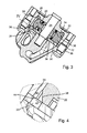
- FIG. 3 shows a section III according to FIG. 2 wherein clearly the axis of rotation 24 and the attached rotor 20 can be seen.
- a wing 22 is shown in section, which rests against the inner peripheral wall 34 of the pump interior 18. The wing 22 is held by two position rings 36 in this position.
- clearly the inlet openings 28 and outlet openings 30 can be seen, which are provided in the housing cover 16 and in the housing bottom 32. In this case, the inlet opening 28 and the outlet opening 30, as realized in the illustrated embodiment, also be provided in a disc 37, whereby the housing cover 16 is easier to produce.
- the rotor 20 has at its two virtual peripheral edges each have a chamfer 38, which in detail in FIG. 4 is shown.
- the chamfer has a first portion 40 which extends parallel to the axis of rotation 24, and a second portion 42 which extends parallel to the housing cover 16 or the housing bottom 32.
- the virtual peripheral edge 44 extends.
- the section 42 is dimensioned to terminate at the edge of the inlet opening 28. In this way it is ensured that the inlet opening 28 is not covered by the rotor 20.
- the fluid can thus flow through the inlet opening 28 and at the chamfer 38 into the working space. Accordingly, the fluid can flow unhindered on the chamfer 38 along the outlet opening 30 and through it out of the pump interior 18.
- FIG. 1 shows a variant of the invention, in which the chamfer 38 extends to the orifice 46.
- the size of the chamfer decreases steadily and ends immediately before the orifice, whereby the fluid is optimally deflected both during inflow and outflow.
Landscapes
- Engineering & Computer Science (AREA)
- Mechanical Engineering (AREA)
- General Engineering & Computer Science (AREA)
- Rotary Pumps (AREA)
- Details And Applications Of Rotary Liquid Pumps (AREA)
Description
- Die Erfindung betrifft eine Flügelzellenpumpe mit wenigstens einem Flügel, einem Pumpengehäuse mit Boden und Deckel und einem darin drehbar gelagerten Rotor, wobei der wenigstens eine Flügel verschieblich in einer Nut im Rotor gelagert ist und wenigstens eine Flügelspitze aufweist, die aus der Außenumfangsfläche des Rotors herausragt und an der Innenumfangsfläche des Pumpengehäuses anliegt, wodurch der Flügel mit dem Boden und dem Deckel einen Saugraum und einen Druckraum definiert, welcher eine im Boden und/oder im Deckel sich befindende, radial außen liegende Einlassöffnung und Auslassöffnung aufweist.
- Aus der
DE 10 2008 036 327 A1 , derDE 101 60 036 A1 oder derDE 10 2007 039 172 A1 ist eine Flügelzellenpumpe bekannt, welche ein Pumpengehäuse aufweist, in welchem ein Rotor angeordnet ist. Dieser Rotor lagert mehrere Flügel, welche an der Innenumfangsseite des Gehäuses anliegen und den Pumpenraum in Arbeitsräume aufteilt. Im Boden des Pumpengehäuses befindet sich eine Einlass- und eine Auslassöffnung, die von den Flügeln überstrichen werden. Es hat sich gezeigt, dass die Einlass- und die Auslassöffnung so weit vom Rotor entfernt sein müssen, dass der Rotor, in welchem die Flügel gelagert sind, nicht über den Öffnungen oder einen Teil der Öffnungen liegen und diesen Teil abdecken. Dies bedeutet aber, dass die Öffnungen stets einen Abstand zum optimalen Ansaug- und Ausstoßpunkt haben. Dieser liegt theoretisch dort, wo der Rotor die Innenumfangsfläche des Pumpengehäuses berührt. DieDE 101 60 036 A1 , die als nächstliegender - Der Erfindung liegt die Aufgabe zugrunde, eine Flügelzellenpumpe mit einem größeren Wirkungsgrad bereitzustellen.
- Diese Aufgabe wird mit einer Flügelzellenpumpe der eingangs genannten Art erfindungsgemäß dadurch gelöst, dass der Rotor an der Umfangskante mit einer Fase versehen ist, die dem die Einlassöffnung und/oder Auslassöffnung aufweisenden Boden und/oder Deckel zugewandt ist.
- Bei der erfindungsgemäßen Flügelzellenpumpe ist die Umfangskante des Rotors, welche sich unmittelbar an der Einlassöffnung und/oder der Auslassöffnung befindet, mit einer Fase versehen, so dass der Rotor im Bereich dieser Umfangskante aufgrund dieser Fase einen gewissen Abstand zum Boden oder Deckel aufweist. Da aber nun der Rotor aufgrund der Fase die Einlassöffnung und/oder Auslassöffnung nicht mehr überdecken kann, kann die Einlassöffnung und/oder Auslassöffnung näher an den optimalen Punkt verlagert werden.
- Dabei erstreckt sich die Fase über einen Abschnitt der Umfangskante. Dieser Abschnitt erstreckt sich zwischen zwei radialen Ausmündungen einer oder mehrerer Nuten für die Aufnahme eines Flügels. Bei einer Einflügelpumpe weist der Rotor eine Nut und bei einer Mehrflügelpumpe entsprechend mehrere Nuten auf. Die Fase erstreckt sich immer zwischen zwei Ausmündungen. Selbst dann, wenn die einzige Nut nur zu einer Seite hin offen ist.
- Erfindungsgemäß ist die Umfangskante im unmittelbaren Anschluss an die Ausmündung der Nut ohne Fase ausgebildet. Die Fase endet also unmittelbar, bevor die Ausmündung der Nut beginnt. Bei einer bevorzugten Ausführungsform ist der Übergang der Fase zum unmittelbaren Anschluss an die Ausmündung der Nut vorteilhaft abgerundet.
- Bei einer bevorzugten Ausführungsform besitzt die Fase einen dreieckförmigen Querschnitt, so dass die Fase einen der Innenumfangsfläche zugewandten ersten Abschnitt und einen dem Boden oder dem Deckel zugewandten zweiten Abschnitt aufweist. Eine derartige Fase ist auf einfache Weise herstellbar.
- Dabei ist die dem anliegenden Boden oder Deckel Abmessung des zweiten Abschnitts so bemessen, dass sie wenigstens so lang ist, wie die radiale Abmessung der Einlassöffnung und/oder der Auslassöffnung. Hierdurch wird sichergestellt, dass die Einlassöffnung und/ oder die Auslassöffnung weder ganz noch teilweise vom Rotor überdeckt wird.
- Um eine optimale Umlenkung der ein- bzw. ausströmenden Fluides zu erreichen, kann die Fase in Richtung der Ausmündung stetig abnehmen. Die Fase wird also in Richtung der Ausmündung kleiner, so dass sie stetig in den Flügel übergeht.
- Weitere Vorteile, Merkmale und Einzelheiten der Erfindung ergeben sich aus den Unteransprüchen sowie der nachfolgenden Beschreibung, in der unter Bezugnahme auf die Zeichnung zwei besonders bevorzugte Ausführungsbeispiele im Einzelnen beschrieben sind.
- In der Zeichnung zeigen:
-
Figur 1 eine Explosionsdarstellung eines Ausführungsbeispiels der erfindungsgemäßen Flügelzellenpumpe; -
Figur 2 eine Draufsicht auf die Flügelzellenpumpe in Richtung des Pfeils II gemäßFigur 1 ; -
Figur 3 einen Schnitt III - III gemäßFigur 2 ; und -
Figur 4 eine vergrößerte Wiedergabe des Ausschnitt IV gemäßFigur 3 . - In der
Figur 1 ist mit dem Bezugszeichen 10 eine Flügelzellenpumpe bezeichnet, bei welcher das Pumpengehäuse 12 geöffnet dargestellt ist. Das Pumpengehäuse 12 besitzt einen Sauganschluss 14, der an einem Gehäusedeckel 16 vorgesehen ist und in einem Pumpeninnenraum 18 ausmündet. In diesem Pumpeninnenraum 18 befindet sich ein insgesamt mit 20 bezeichneter Rotor, in welchem eine Vielzahl von Flügeln 22 orthogonal zur Drehachse 24 verschieblich gelagert ist. Ein jeder Flügel 22 ist in einer Nut 26 radial verschieblich gelagert, wobei die Nuten 26 gleichmäßig über den Umfang am Rotor 20 vorgesehen sind. Der Pumpeninnenraum 18 beherbergt den Rotor 20 mit den Flügeln 22 wobei die Flügel 22 zwischen sich die Arbeitsräume definieren. In diese Arbeitsräume mündet der Sauganschluss 14 über eine Einlassöffnung ein, wobei das komprimierte Fluid über eine Auslassöffnung 30 ausgestoßen wird. Im Gehäuseboden 32 ist die Auslassöffnung nicht sichtbar. - Die
Figur 3 zeigt einen Schnitt III gemäßFigur 2 wobei deutlich die Drehachse 24 und der daran befestigte Rotor 20 erkennbar sind.
Außerdem ist noch ein Flügel 22 im Schnitt dargestellt, der an der Innenumfangswand 34 des Pumpeninnenraums 18 anliegt. Der Flügel 22 wird von zwei Positionsringen 36 in dieser Lage gehalten. Außerdem sind deutlich die Einlassöffnungen 28 und Auslassöffnungen 30 erkennbar, die im Gehäusedeckel 16 und im Gehäuseboden 32 vorgesehen sind. Dabei können die Einlassöffnung 28 und die Auslassöffnung 30, wie im dargestellten Ausführungsbeispiel realisiert, auch in einer Scheibe 37 vorgesehen sein, wodurch der Gehäusedeckel 16 einfacher herstellbar wird. - Der Rotor 20 weist an seinen beiden virtuellen Umfangskanten jeweils eine Fase 38 auf, die im Detail in
Figur 4 dargestellt ist. Die Fase besitzt eine ersten Abschnitt 40, der sich parallel zur Drehachse 24 erstreckt, und einen zweiten Abschnitt 42, der sich parallel zum Gehäusedeckel 16 oder zum Gehäuseboden 32 erstreckt. Am Schnittpunkt der beiden Abschnitte 40 und 42 verläuft die virtuelle Umfangskante 44. Der Abschnitt 42 ist so bemessen, dass er am Rand der Einlassöffnung 28 endet. Auf diese Weise ist sichergestellt, dass die Einlassöffnung 28 vom Rotor 20 nicht überdeckt wird. Das Fluid kann also durch die Einlassöffnung 28 hindurch und an der Fase 38 in den Arbeitsraum strömen. Entsprechend kann das Fluid ungehindert an der Fase 38 entlang zur Auslassöffnung 30 und durch diese hindurch aus dem Pumpeninnenraum 18 ausströmen. - Die
Figur 1 zeigt eine Variante der Erfindung, bei der sich die Fase 38 bis an die Ausmündung 46 heranreicht. Bei einer nicht dargestellten Variante nimmt die Größe der Fase stetig ab und endet unmittelbar vor der Ausmündung, wodurch das Fluid sowohl beim einströmen als auch beim Ausströmen optimal umgelenkt wird.
Claims (5)
- Flügelzellenpumpe (10) mit wenigstens einem Flügel (22), einem Pumpengehäuse (12) mit Gehäuseboden (32) und Gehäusedeckel (16) und einem darin drehbar gelagerten Rotor (20), wobei der wenigstens eine Flügel (22) verschieblich in einer Nut (26) im Rotor (20) gelagert ist und wenigstens eine Flügelspitze aufweist, die aus der Außenumfangsfläche des Rotors (20) herausragt und an der Innenumfangswand (34) des Pumpengehäuses (12) anliegt, wobei der wenigstens eine Flügel (22) mit dem Gehäuseboden (32) und dem Gehäusedeckel (16) einen Arbeitsraum definiert, welcher eine im Gehäuseboden (32) und/oder im Gehäusedeckel (16) sich befindende, radial außen liegende Einlassöffnung (28) und Auslassöffnung (30) aufweist, wobei der Rotor (20) an der Umfangskante (44) mit einer Fase (38) versehen ist, die dem die Einlassöffnung (28) und/ oder Auslassöffnung (30) aufweisenden Gehäuseboden (32) und/oder Gehäusedeckel (16) zugewandt ist, wobei sich die Fase (38) über einen Abschnitt (46) der Umfangskante (44) erstreckt, dieser Abschnitt (46) sich zwischen zwei radialen Ausmündungen einer oder mehrerer Nuten (26) für die Aufnahme eines Flügels (22) erstreckt, dadurch gekennzeichnet, dass die Umfangskante (44) im unmittelbaren Anschluss an die Ausmündung (46) der Nut (26) ohne Fase ausgebildet ist.
- Flügelzellenpumpe nach Anspruch 1, dadurch gekennzeichnet, dass die Fase (38) einen der Innenumfangswand (34) zugewandten ersten Abschnitt (40) und einen dem Boden (32) oder dem Deckel (16) zugewandten zweiten Abschnitt (42) aufweist.
- Flügelzellenpumpe nach Anspruch 2, dadurch gekennzeichnet, dass der zweite Abschnitt (42) wenigstens so lang ist, wie die radiale Abmessung der Einlassöffnung (28) und/oder der Auslassöffnung (30).
- Flügelzellenpumpe nach Anspruch 1, dadurch gekennzeichnet, dass die Fase (38) in Richtung der Ausmündung (46) stetig abnimmt.
- Flügelzellenpumpe nach Anspruch 1, dadurch gekennzeichnet, dass der Übergang der Fase (38) zum unmittelbaren Anschluss an die Ausmündung (46) der Nut (26) abgerundet ist.
Applications Claiming Priority (2)
| Application Number | Priority Date | Filing Date | Title |
|---|---|---|---|
| DE102010039344A DE102010039344A1 (de) | 2010-08-16 | 2010-08-16 | Flügelzellenpumpe |
| PCT/EP2011/062941 WO2012022595A2 (de) | 2010-08-16 | 2011-07-27 | Flügelzellenpumpe |
Publications (2)
| Publication Number | Publication Date |
|---|---|
| EP2606235A2 EP2606235A2 (de) | 2013-06-26 |
| EP2606235B1 true EP2606235B1 (de) | 2014-09-03 |
Family
ID=44629528
Family Applications (1)
| Application Number | Title | Priority Date | Filing Date |
|---|---|---|---|
| EP11739038.5A Active EP2606235B1 (de) | 2010-08-16 | 2011-07-27 | Flügelzellenpumpe |
Country Status (5)
| Country | Link |
|---|---|
| US (1) | US9011125B2 (de) |
| EP (1) | EP2606235B1 (de) |
| CN (1) | CN103261692B (de) |
| DE (1) | DE102010039344A1 (de) |
| WO (1) | WO2012022595A2 (de) |
Families Citing this family (3)
| Publication number | Priority date | Publication date | Assignee | Title |
|---|---|---|---|---|
| CN103195707A (zh) * | 2013-04-12 | 2013-07-10 | 贾东明 | 滑片式旋转活塞 |
| DE102015120798A1 (de) * | 2015-12-01 | 2017-06-01 | Robert Bosch Automotive Steering Gmbh | Verdrängerpumpe |
| US11688925B2 (en) | 2020-04-10 | 2023-06-27 | Commscope Technologies Llc | Module for a cellular communications monopole |
Family Cites Families (6)
| Publication number | Priority date | Publication date | Assignee | Title |
|---|---|---|---|---|
| DE2631152C2 (de) * | 1976-07-10 | 1985-08-08 | Volkswagenwerk Ag, 3180 Wolfsburg | Flügelzellen-Vakuumpumpe |
| DE4143466C2 (de) * | 1991-03-20 | 1997-05-15 | Rexroth Mannesmann Gmbh | Steuerscheibe für Flügelzellenpumpe |
| DE10160036A1 (de) * | 2000-12-13 | 2002-09-12 | Luk Fahrzeug Hydraulik | Flügelzellenmaschine |
| JP2008128116A (ja) * | 2006-11-21 | 2008-06-05 | Matsushita Electric Works Ltd | ベーンポンプ |
| DE102007039172B4 (de) * | 2007-06-05 | 2024-02-15 | Robert Bosch Gmbh | Flügelzellenpumpe |
| DE102008036327A1 (de) | 2008-07-28 | 2010-02-04 | Joma-Hydromechanic Gmbh | Flügelzellenpumpe |
-
2010
- 2010-08-16 DE DE102010039344A patent/DE102010039344A1/de not_active Withdrawn
-
2011
- 2011-07-27 US US13/817,330 patent/US9011125B2/en active Active
- 2011-07-27 EP EP11739038.5A patent/EP2606235B1/de active Active
- 2011-07-27 CN CN201180039624.9A patent/CN103261692B/zh active Active
- 2011-07-27 WO PCT/EP2011/062941 patent/WO2012022595A2/de not_active Ceased
Also Published As
| Publication number | Publication date |
|---|---|
| CN103261692A (zh) | 2013-08-21 |
| US20130216419A1 (en) | 2013-08-22 |
| WO2012022595A2 (de) | 2012-02-23 |
| EP2606235A2 (de) | 2013-06-26 |
| DE102010039344A1 (de) | 2012-02-16 |
| CN103261692B (zh) | 2015-09-09 |
| WO2012022595A3 (de) | 2013-04-11 |
| US9011125B2 (en) | 2015-04-21 |
Similar Documents
| Publication | Publication Date | Title |
|---|---|---|
| EP3140548B1 (de) | Laufrad, insbesondere für eine seitenkanalmaschine | |
| DE102010046870B4 (de) | Seitenkanalgebläse, insbesondere Sekundärluftgebläse für eine Verbrennungskraftmaschine | |
| DE10327574B4 (de) | Laufrad für eine Kraftstoffpumpe | |
| DE102009056010B4 (de) | Flügelzellenpumpe | |
| EP2122176B1 (de) | Vakuumpumpe | |
| DE2221541A1 (de) | Fluegelzellenkompressor | |
| EP2643595B1 (de) | Selbstreinigende schraubenzentrifugalradpumpe mit rezirkulation hinter dem schaufelrad | |
| DE102009035000B4 (de) | Flügelzellenmaschine | |
| WO2012022595A2 (de) | Flügelzellenpumpe | |
| EP2852762B1 (de) | Drehkolbenpumpe mit optimierten ein- und auslässen | |
| DE2349651A1 (de) | Druckventil | |
| DE1808829C3 (de) | Radial ventilator | |
| DE3210161C1 (de) | Fluessigkeitsringkompressor fuer Gase | |
| DE102005008388A1 (de) | Laufrad und Seitenkanalmaschine mit Laufrad | |
| EP3805521A1 (de) | Flügelzellenpumpe | |
| WO2007140758A1 (de) | Flügelzellenpumpe | |
| DE1528895C3 (de) | Zentrifugalpumpe | |
| EP2160513B1 (de) | Hybridpumpe zum fördern eines flüssigen pumpmediums | |
| DE2153220B2 (de) | ||
| EP3179110B1 (de) | Doppelpumpe | |
| DE202012102918U1 (de) | Spiralstrom-Konstantdruckpumpe | |
| DE3135697C2 (de) | Regelbare Flügelzellenpumpe | |
| DE1628394C3 (de) | Flüssigkeitsring Verdichter | |
| DE102021125708A1 (de) | Strömungsleitstruktur | |
| EP2986855A1 (de) | Laufrad für eine kreiselpumpe und kreiselpumpe |
Legal Events
| Date | Code | Title | Description |
|---|---|---|---|
| PUAI | Public reference made under article 153(3) epc to a published international application that has entered the european phase |
Free format text: ORIGINAL CODE: 0009012 |
|
| 17P | Request for examination filed |
Effective date: 20130130 |
|
| AK | Designated contracting states |
Kind code of ref document: A2 Designated state(s): AL AT BE BG CH CY CZ DE DK EE ES FI FR GB GR HR HU IE IS IT LI LT LU LV MC MK MT NL NO PL PT RO RS SE SI SK SM TR |
|
| GRAP | Despatch of communication of intention to grant a patent |
Free format text: ORIGINAL CODE: EPIDOSNIGR1 |
|
| DAX | Request for extension of the european patent (deleted) | ||
| INTG | Intention to grant announced |
Effective date: 20140224 |
|
| GRAS | Grant fee paid |
Free format text: ORIGINAL CODE: EPIDOSNIGR3 |
|
| GRAA | (expected) grant |
Free format text: ORIGINAL CODE: 0009210 |
|
| AK | Designated contracting states |
Kind code of ref document: B1 Designated state(s): AL AT BE BG CH CY CZ DE DK EE ES FI FR GB GR HR HU IE IS IT LI LT LU LV MC MK MT NL NO PL PT RO RS SE SI SK SM TR |
|
| REG | Reference to a national code |
Ref country code: GB Ref legal event code: FG4D Free format text: NOT ENGLISH |
|
| REG | Reference to a national code |
Ref country code: CH Ref legal event code: EP Ref country code: AT Ref legal event code: REF Ref document number: 685777 Country of ref document: AT Kind code of ref document: T Effective date: 20140915 |
|
| REG | Reference to a national code |
Ref country code: IE Ref legal event code: FG4D Free format text: LANGUAGE OF EP DOCUMENT: GERMAN |
|
| REG | Reference to a national code |
Ref country code: DE Ref legal event code: R096 Ref document number: 502011004278 Country of ref document: DE Effective date: 20141016 |
|
| PG25 | Lapsed in a contracting state [announced via postgrant information from national office to epo] |
Ref country code: SE Free format text: LAPSE BECAUSE OF FAILURE TO SUBMIT A TRANSLATION OF THE DESCRIPTION OR TO PAY THE FEE WITHIN THE PRESCRIBED TIME-LIMIT Effective date: 20140903 Ref country code: NO Free format text: LAPSE BECAUSE OF FAILURE TO SUBMIT A TRANSLATION OF THE DESCRIPTION OR TO PAY THE FEE WITHIN THE PRESCRIBED TIME-LIMIT Effective date: 20141203 Ref country code: LT Free format text: LAPSE BECAUSE OF FAILURE TO SUBMIT A TRANSLATION OF THE DESCRIPTION OR TO PAY THE FEE WITHIN THE PRESCRIBED TIME-LIMIT Effective date: 20140903 Ref country code: ES Free format text: LAPSE BECAUSE OF FAILURE TO SUBMIT A TRANSLATION OF THE DESCRIPTION OR TO PAY THE FEE WITHIN THE PRESCRIBED TIME-LIMIT Effective date: 20140903 Ref country code: FI Free format text: LAPSE BECAUSE OF FAILURE TO SUBMIT A TRANSLATION OF THE DESCRIPTION OR TO PAY THE FEE WITHIN THE PRESCRIBED TIME-LIMIT Effective date: 20140903 Ref country code: GR Free format text: LAPSE BECAUSE OF FAILURE TO SUBMIT A TRANSLATION OF THE DESCRIPTION OR TO PAY THE FEE WITHIN THE PRESCRIBED TIME-LIMIT Effective date: 20141204 |
|
| REG | Reference to a national code |
Ref country code: NL Ref legal event code: VDEP Effective date: 20140903 |
|
| REG | Reference to a national code |
Ref country code: LT Ref legal event code: MG4D |
|
| PG25 | Lapsed in a contracting state [announced via postgrant information from national office to epo] |
Ref country code: RS Free format text: LAPSE BECAUSE OF FAILURE TO SUBMIT A TRANSLATION OF THE DESCRIPTION OR TO PAY THE FEE WITHIN THE PRESCRIBED TIME-LIMIT Effective date: 20140903 Ref country code: LV Free format text: LAPSE BECAUSE OF FAILURE TO SUBMIT A TRANSLATION OF THE DESCRIPTION OR TO PAY THE FEE WITHIN THE PRESCRIBED TIME-LIMIT Effective date: 20140903 Ref country code: HR Free format text: LAPSE BECAUSE OF FAILURE TO SUBMIT A TRANSLATION OF THE DESCRIPTION OR TO PAY THE FEE WITHIN THE PRESCRIBED TIME-LIMIT Effective date: 20140903 Ref country code: CY Free format text: LAPSE BECAUSE OF FAILURE TO SUBMIT A TRANSLATION OF THE DESCRIPTION OR TO PAY THE FEE WITHIN THE PRESCRIBED TIME-LIMIT Effective date: 20140903 |
|
| PG25 | Lapsed in a contracting state [announced via postgrant information from national office to epo] |
Ref country code: NL Free format text: LAPSE BECAUSE OF FAILURE TO SUBMIT A TRANSLATION OF THE DESCRIPTION OR TO PAY THE FEE WITHIN THE PRESCRIBED TIME-LIMIT Effective date: 20140903 |
|
| PG25 | Lapsed in a contracting state [announced via postgrant information from national office to epo] |
Ref country code: EE Free format text: LAPSE BECAUSE OF FAILURE TO SUBMIT A TRANSLATION OF THE DESCRIPTION OR TO PAY THE FEE WITHIN THE PRESCRIBED TIME-LIMIT Effective date: 20140903 Ref country code: PT Free format text: LAPSE BECAUSE OF FAILURE TO SUBMIT A TRANSLATION OF THE DESCRIPTION OR TO PAY THE FEE WITHIN THE PRESCRIBED TIME-LIMIT Effective date: 20150105 Ref country code: SK Free format text: LAPSE BECAUSE OF FAILURE TO SUBMIT A TRANSLATION OF THE DESCRIPTION OR TO PAY THE FEE WITHIN THE PRESCRIBED TIME-LIMIT Effective date: 20140903 Ref country code: IS Free format text: LAPSE BECAUSE OF FAILURE TO SUBMIT A TRANSLATION OF THE DESCRIPTION OR TO PAY THE FEE WITHIN THE PRESCRIBED TIME-LIMIT Effective date: 20150103 Ref country code: CZ Free format text: LAPSE BECAUSE OF FAILURE TO SUBMIT A TRANSLATION OF THE DESCRIPTION OR TO PAY THE FEE WITHIN THE PRESCRIBED TIME-LIMIT Effective date: 20140903 Ref country code: RO Free format text: LAPSE BECAUSE OF FAILURE TO SUBMIT A TRANSLATION OF THE DESCRIPTION OR TO PAY THE FEE WITHIN THE PRESCRIBED TIME-LIMIT Effective date: 20140903 |
|
| PG25 | Lapsed in a contracting state [announced via postgrant information from national office to epo] |
Ref country code: PL Free format text: LAPSE BECAUSE OF FAILURE TO SUBMIT A TRANSLATION OF THE DESCRIPTION OR TO PAY THE FEE WITHIN THE PRESCRIBED TIME-LIMIT Effective date: 20140903 |
|
| REG | Reference to a national code |
Ref country code: DE Ref legal event code: R097 Ref document number: 502011004278 Country of ref document: DE |
|
| PLBE | No opposition filed within time limit |
Free format text: ORIGINAL CODE: 0009261 |
|
| STAA | Information on the status of an ep patent application or granted ep patent |
Free format text: STATUS: NO OPPOSITION FILED WITHIN TIME LIMIT |
|
| PG25 | Lapsed in a contracting state [announced via postgrant information from national office to epo] |
Ref country code: DK Free format text: LAPSE BECAUSE OF FAILURE TO SUBMIT A TRANSLATION OF THE DESCRIPTION OR TO PAY THE FEE WITHIN THE PRESCRIBED TIME-LIMIT Effective date: 20140903 |
|
| 26N | No opposition filed |
Effective date: 20150604 |
|
| PG25 | Lapsed in a contracting state [announced via postgrant information from national office to epo] |
Ref country code: IT Free format text: LAPSE BECAUSE OF FAILURE TO SUBMIT A TRANSLATION OF THE DESCRIPTION OR TO PAY THE FEE WITHIN THE PRESCRIBED TIME-LIMIT Effective date: 20140903 |
|
| PG25 | Lapsed in a contracting state [announced via postgrant information from national office to epo] |
Ref country code: SI Free format text: LAPSE BECAUSE OF FAILURE TO SUBMIT A TRANSLATION OF THE DESCRIPTION OR TO PAY THE FEE WITHIN THE PRESCRIBED TIME-LIMIT Effective date: 20140903 |
|
| PG25 | Lapsed in a contracting state [announced via postgrant information from national office to epo] |
Ref country code: MC Free format text: LAPSE BECAUSE OF FAILURE TO SUBMIT A TRANSLATION OF THE DESCRIPTION OR TO PAY THE FEE WITHIN THE PRESCRIBED TIME-LIMIT Effective date: 20140903 |
|
| REG | Reference to a national code |
Ref country code: CH Ref legal event code: PL |
|
| GBPC | Gb: european patent ceased through non-payment of renewal fee |
Effective date: 20150727 |
|
| PG25 | Lapsed in a contracting state [announced via postgrant information from national office to epo] |
Ref country code: LU Free format text: LAPSE BECAUSE OF FAILURE TO SUBMIT A TRANSLATION OF THE DESCRIPTION OR TO PAY THE FEE WITHIN THE PRESCRIBED TIME-LIMIT Effective date: 20150727 |
|
| REG | Reference to a national code |
Ref country code: IE Ref legal event code: MM4A |
|
| PG25 | Lapsed in a contracting state [announced via postgrant information from national office to epo] |
Ref country code: GB Free format text: LAPSE BECAUSE OF NON-PAYMENT OF DUE FEES Effective date: 20150727 Ref country code: CH Free format text: LAPSE BECAUSE OF NON-PAYMENT OF DUE FEES Effective date: 20150731 Ref country code: LI Free format text: LAPSE BECAUSE OF NON-PAYMENT OF DUE FEES Effective date: 20150731 |
|
| REG | Reference to a national code |
Ref country code: FR Ref legal event code: ST Effective date: 20160331 |
|
| PG25 | Lapsed in a contracting state [announced via postgrant information from national office to epo] |
Ref country code: FR Free format text: LAPSE BECAUSE OF NON-PAYMENT OF DUE FEES Effective date: 20150731 |
|
| PG25 | Lapsed in a contracting state [announced via postgrant information from national office to epo] |
Ref country code: IE Free format text: LAPSE BECAUSE OF NON-PAYMENT OF DUE FEES Effective date: 20150727 |
|
| PG25 | Lapsed in a contracting state [announced via postgrant information from national office to epo] |
Ref country code: MT Free format text: LAPSE BECAUSE OF FAILURE TO SUBMIT A TRANSLATION OF THE DESCRIPTION OR TO PAY THE FEE WITHIN THE PRESCRIBED TIME-LIMIT Effective date: 20140903 |
|
| PG25 | Lapsed in a contracting state [announced via postgrant information from national office to epo] |
Ref country code: BG Free format text: LAPSE BECAUSE OF FAILURE TO SUBMIT A TRANSLATION OF THE DESCRIPTION OR TO PAY THE FEE WITHIN THE PRESCRIBED TIME-LIMIT Effective date: 20140903 Ref country code: HU Free format text: LAPSE BECAUSE OF FAILURE TO SUBMIT A TRANSLATION OF THE DESCRIPTION OR TO PAY THE FEE WITHIN THE PRESCRIBED TIME-LIMIT; INVALID AB INITIO Effective date: 20110727 Ref country code: SM Free format text: LAPSE BECAUSE OF FAILURE TO SUBMIT A TRANSLATION OF THE DESCRIPTION OR TO PAY THE FEE WITHIN THE PRESCRIBED TIME-LIMIT Effective date: 20140903 |
|
| PG25 | Lapsed in a contracting state [announced via postgrant information from national office to epo] |
Ref country code: BE Free format text: LAPSE BECAUSE OF NON-PAYMENT OF DUE FEES Effective date: 20150731 |
|
| REG | Reference to a national code |
Ref country code: AT Ref legal event code: MM01 Ref document number: 685777 Country of ref document: AT Kind code of ref document: T Effective date: 20160727 |
|
| PG25 | Lapsed in a contracting state [announced via postgrant information from national office to epo] |
Ref country code: AT Free format text: LAPSE BECAUSE OF NON-PAYMENT OF DUE FEES Effective date: 20160727 |
|
| PG25 | Lapsed in a contracting state [announced via postgrant information from national office to epo] |
Ref country code: MK Free format text: LAPSE BECAUSE OF FAILURE TO SUBMIT A TRANSLATION OF THE DESCRIPTION OR TO PAY THE FEE WITHIN THE PRESCRIBED TIME-LIMIT Effective date: 20140903 Ref country code: TR Free format text: LAPSE BECAUSE OF FAILURE TO SUBMIT A TRANSLATION OF THE DESCRIPTION OR TO PAY THE FEE WITHIN THE PRESCRIBED TIME-LIMIT Effective date: 20140903 |
|
| PG25 | Lapsed in a contracting state [announced via postgrant information from national office to epo] |
Ref country code: AL Free format text: LAPSE BECAUSE OF FAILURE TO SUBMIT A TRANSLATION OF THE DESCRIPTION OR TO PAY THE FEE WITHIN THE PRESCRIBED TIME-LIMIT Effective date: 20140903 |
|
| REG | Reference to a national code |
Ref country code: DE Ref legal event code: R084 Ref document number: 502011004278 Country of ref document: DE |
|
| P01 | Opt-out of the competence of the unified patent court (upc) registered |
Effective date: 20230620 |
|
| PGFP | Annual fee paid to national office [announced via postgrant information from national office to epo] |
Ref country code: DE Payment date: 20250916 Year of fee payment: 15 |