EP2605250B1 - Ignition lead - Google Patents
Ignition lead Download PDFInfo
- Publication number
- EP2605250B1 EP2605250B1 EP12195295.6A EP12195295A EP2605250B1 EP 2605250 B1 EP2605250 B1 EP 2605250B1 EP 12195295 A EP12195295 A EP 12195295A EP 2605250 B1 EP2605250 B1 EP 2605250B1
- Authority
- EP
- European Patent Office
- Prior art keywords
- ignition lead
- conduit
- metal layer
- continuous
- continuous metal
- Prior art date
- Legal status (The legal status is an assumption and is not a legal conclusion. Google has not performed a legal analysis and makes no representation as to the accuracy of the status listed.)
- Active
Links
Images



Classifications
-
- H—ELECTRICITY
- H01—ELECTRIC ELEMENTS
- H01B—CABLES; CONDUCTORS; INSULATORS; SELECTION OF MATERIALS FOR THEIR CONDUCTIVE, INSULATING OR DIELECTRIC PROPERTIES
- H01B7/00—Insulated conductors or cables characterised by their form
- H01B7/0063—Ignition cables
-
- F—MECHANICAL ENGINEERING; LIGHTING; HEATING; WEAPONS; BLASTING
- F16—ENGINEERING ELEMENTS AND UNITS; GENERAL MEASURES FOR PRODUCING AND MAINTAINING EFFECTIVE FUNCTIONING OF MACHINES OR INSTALLATIONS; THERMAL INSULATION IN GENERAL
- F16L—PIPES; JOINTS OR FITTINGS FOR PIPES; SUPPORTS FOR PIPES, CABLES OR PROTECTIVE TUBING; MEANS FOR THERMAL INSULATION IN GENERAL
- F16L11/00—Hoses, i.e. flexible pipes
- F16L11/14—Hoses, i.e. flexible pipes made of rigid material, e.g. metal or hard plastics
- F16L11/16—Hoses, i.e. flexible pipes made of rigid material, e.g. metal or hard plastics wound from profiled strips or bands
-
- H—ELECTRICITY
- H04—ELECTRIC COMMUNICATION TECHNIQUE
- H04B—TRANSMISSION
- H04B15/00—Suppression or limitation of noise or interference
- H04B15/02—Reducing interference from electric apparatus by means located at or near the interfering apparatus
- H04B15/025—Reducing interference from ignition apparatus of fuel engines
Definitions
- Contemporary reciprocating and gas turbine aircraft engines include ignition systems having an ignition lead that conducts a large current, high voltage ignition pulse from an exciter to an igniter, which may then transform the pulse received from the ignition lead into an electrical spark, which ignites a fuel and air mixture in a combustor of the engine.
- the conductor or inner lead wire of the ignition lead is often surrounded by one or more metallic braided sleeves and/or hermetic conduits for protection, ground return, and the prevention of electromagnetic interference.
- Installation and attachment of the braided sleeve may be labor intensive.
- the braided sleeve may cause interference with cooling air flow that is delivered through the conduit to the igniter terminal and may be prone to sustaining mechanical damage in severe vibratory environments.
- the braided sleeve has also been known to trap debris, which may ultimately obstruct the intended cooling air supply and may require additional design features to support the braiding and maintain well defined cooling flow paths.
- GB 677,656 relates to electrostatic screening conduits for electric conductors and discloses features generally corresponding to the preamble of claim 1 herein.
- An ignition lead for coupling an exciter to an igniter is provided in accordance with claim 1 herein.
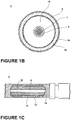
- FIG 1A is a schematic illustration of an exemplary ignition system 2 that may be used with a gas turbine engine 3 and may include an exciter 4, at least one igniter 5, and at least one ignition lead 6 coupled between the exciter 4 and igniter 5.
- the ignition lead 6 may generally include a coaxial construction for electromagnetic shielding purposes.
- An inner portion may include a center conductor 7 for providing the ignition pulses, an electrically insulating jacket 8, and a low-resistance braid 9 used as a return path for the electrical current.
- the insulating jacket 8 may be formed from any suitable material including an elastomeric or polytetrafluoroethylene-based (PTFE) material.
- PTFE polytetrafluoroethylene-based
- the braid 9 may be spaced from the insulating jacket 8 by an air passage 10. This inner portion may then be surrounded by a flexible non-collapsible metal conduit 12, which may provide the ignition lead 6 with suitable structural integrity to maintain the air passage 10.
- the braid 9 may be brazed at each end of the ignition lead 6 to the conduit 12.
- a nickel-based overbraid 14 may be provided over the conduit 12 to protect the internal components of the ignition lead 6 from abrasion and other damage as well as provide added EMI protection.
- Figure 1C illustrates a side view of the ignition lead 6 with a portion cutaway to show the interior of the ignition lead 6.
- the conduit 12 may be formed by a series of strip-wound and brazed convolutions. Alternatively, seam-welded or seamless corrugations are also used in some cases.
- the conduit 12 may provide mechanical and environmental protection for the center conductor 7 and generally requires the use of iron based alloys with good strength but relatively poor conductivity.
- the poor conductivity is addressed by including the low-resistance braid 9, which may often be formed from copper or other conductive metal that is applied to the convolutions forming the conduit 12 and acts as the current return path.
- the braid 9 may also provide additional EMI protection.
- air is able to flow through air passage 10 such that it cools the insulating jacket 8 as well as any other polymeric materials inside the igniter 5 and ignition lead 6.
- Locating the braid 9 within the conduit 12 may be advantageous because the conduit 12 helps protect the braid 9 from physical damage as well as electromagnetic interference. Over time vibration and other conditions may cause the braid 9 to internally sag, collapse, and/or bunch up, in which case the air passage 10 may become at least partially closed off, thus inhibiting air flow through the air passage 10, which may lead to high temperatures and thermal and/or dielectric breakdown of the insulating jacket 8.
- FIG. 2A illustrates an ignition lead 20 according to one embodiment of the invention.
- a center conductor 22, a conduit 24, and an electrical return path 26 may be included in the ignition lead 20.
- the center conductor 22 may conduct a high current and high voltage from the exciter to the igniter as described above.
- An electrical insulation jacket 28 may surround the center conductor 22 and may electrically isolate the center conductor 22 from the conduit 24 and the electrical return path 26.
- the conduit 24 is illustrated as surrounding the center conductor 22 and protects the center conductor 22 from the surrounding environment provided by the jet engine, which may include a severe operating environment having high vibration and temperature extremes.
- the conduit 24 may form convoluted metal tubing around the center conductor 22.
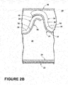
- the electrical return path 26 may include a continuous layer 32 of conductive material affixed to the conduit 24. While the continuous layer 32 forming the electrical return path 26 is illustrated as being affixed to the interior surface 34 of the conduit 24 it is contemplated that the continuous layer 32 forming the electrical return path 26 may be affixed to either the outside surface 36 or the interior surface 34 of the conduit 24 or both the interior surface 34 and outside surface 36 simultaneously.
- the conduit 24 includes a first continuous metal layer 38 wherein the continuous layer 32 forming the electrical return path 26 includes a second continuous metal layer.
- the second continuous metal layer forming the electrical return path 26 may be more conductive than the first continuous metal layer 38 forming the conduit 24 while the first continuous metal layer 38 may be less oxidative than the second continuous metal layer forming the electrical return path 26. In this manner, the conduit may be less likely to corrode and rust within the surrounding environment.
- the conduit 24 may be formed from a composition including an alloy of at least nickel and iron.
- the second continuous metal layer forming the electrical return path 26 may by way of non-limiting examples include copper or a composition including copper.
- a chafe guard 40 may also be included in the ignition lead 20 and may surround the conduit 24. The chafe guard 40 may be included to provide additional mechanical protection to the ignition lead 20.
- the chafe guard 40 may be formed from a layer of polyetheretherketone (PEEK) braiding or a layer of PTFE spiral wrap. It is also contemplated that a nickel braid (not shown) may be included surrounding the conduit 24 and that the chafe guard 40 may be in addition to the nickel braid.
- PEEK polyetheretherketone
- a nickel braid may be included surrounding the conduit 24 and that the chafe guard 40 may be in addition to the nickel braid.
- the continuous layer 32 forming the electrical return path 26 may be affixed or attached to the conduit 24 in any suitable manner.
- the continuous layer 32 may be achieved through plating a continuous metal layer such as copper or a composition including copper on the first continuous metal layer 38.
- the continuous layer may be achieved through electroplating, hydroforming, bilayer rolling, physical vapor deposition, chemical vapor deposition, brush painting, and spray painting.
- the first and second continuous layers may alternatively be formed from a bimetal strip.
- a bimetal strip may be formed into the conduit 24 and electrical return path 26. This may be done in any suitable manner including by way of non-limiting examples that the bimetal strip may be helically wound to form the conduit 24 and electrical return path 26 and that the bimetal strip may be formed into convolutions. The portions of the bimetal strip may be joined together by brazing such that a brazed joint 42 may be formed. In this manner, the conduit 24 and electrical return 26 may be formed from a wound, multi-layer strip having at least a first continuous metal layer and a second continuous metal layer. It is also contemplated that a trimetal strip may be used and that in this manner a chafe guard may also be formed using the trimetal strip.
- the conduit 24 may be formed such that it has a corrugated configuration and may be flexible. It is contemplated that the continuous layer 32 forming the electrical return path 26 is thin enough to be flexible and not inhibit flex of the conduit 24. This may be true regardless of how the conduit 24 and electrical return path 26 are formed as it is contemplated that the bimetal strip may also be flexible. While, the continuous layer 32 may appear broken in this illustration it will be understood that the continuous metal forming the electrical return path 26 is helically wrapped and is indeed continuous.
- the first and second continuous metal layers may have different shielding properties to enhance the EMI shielding and RFI shielding to protect the ignition lead 20.
- the first and second continuous metal layers may have different radio frequency shielding properties.
- that continuous layer 32 may be better at magnetic field reflection while the first continuous metal layer 38 may be better at absorption loss across the whole frequency range.
- the first continuous metal layer may shield frequencies up to 40GHz, and the second continuous metal layer may shield frequencies in the range of 10kHz to 10GHz.
- the above described embodiments eliminate the inner braid, which results in a variety of benefits as a solid conductor is used instead of the stranded conductor formed by conventional sleeving, mesh, or overbraid.
- improved mechanical robustness and superior shielding relative to the metal braid may be realized as the braid is a relatively fragile design element and any sort of opening or seam within the braid is a potential radiation emission leak path.
- the elimination of the braid and the use of a thin continuous conductive layer may also provide a reduced envelope and a reduction in weight, which may provide an advantage during operation of the aircraft.
- the elimination of the braid also results in the elimination of labor intensive processes during manufacture.
Landscapes
- Engineering & Computer Science (AREA)
- General Engineering & Computer Science (AREA)
- Mechanical Engineering (AREA)
- Insulated Conductors (AREA)
- Ignition Installations For Internal Combustion Engines (AREA)
- Control Of Turbines (AREA)
Applications Claiming Priority (1)
| Application Number | Priority Date | Filing Date | Title |
|---|---|---|---|
| US13/316,852 US8766095B2 (en) | 2011-12-12 | 2011-12-12 | Ignition lead |
Publications (2)
| Publication Number | Publication Date |
|---|---|
| EP2605250A1 EP2605250A1 (en) | 2013-06-19 |
| EP2605250B1 true EP2605250B1 (en) | 2018-02-21 |
Family
ID=47627904
Family Applications (1)
| Application Number | Title | Priority Date | Filing Date |
|---|---|---|---|
| EP12195295.6A Active EP2605250B1 (en) | 2011-12-12 | 2012-12-03 | Ignition lead |
Country Status (4)
| Country | Link |
|---|---|
| US (1) | US8766095B2 (https=) |
| EP (1) | EP2605250B1 (https=) |
| JP (1) | JP6188049B2 (https=) |
| CA (1) | CA2797518A1 (https=) |
Families Citing this family (4)
| Publication number | Priority date | Publication date | Assignee | Title |
|---|---|---|---|---|
| CN204408625U (zh) * | 2015-01-21 | 2015-06-17 | 瑞声声学科技(深圳)有限公司 | Mems麦克风 |
| US10590887B2 (en) | 2016-05-20 | 2020-03-17 | Alphaport, Inc. | Spark exciter operational unit |
| DE102018118262A1 (de) * | 2018-07-27 | 2020-01-30 | Rosenberger Hochfrequenztechnik Gmbh & Co. Kg | Vorrichtung zur Zündung eines Kraftstoffgemisches, Übertragungselement zur Übertragung einer Hochvolt-Zündspannung, Zündeinrichtung und Schaltungseinrichtung |
| US11348705B2 (en) | 2018-10-19 | 2022-05-31 | Rolls-Royce Corporation | Coaxial cable system for gas turbine engine |
Family Cites Families (19)
| Publication number | Priority date | Publication date | Assignee | Title |
|---|---|---|---|---|
| US2028793A (en) | 1931-07-11 | 1936-01-28 | Joseph J Mascuch | Interference preventing cable |
| GB677656A (en) | 1950-03-09 | 1952-08-20 | Avica Equip | Improvements in or relating to electrostatic screening conduits for electric conductors |
| FR2071132A5 (https=) | 1969-12-18 | 1971-09-17 | Cables De Lyon Geoffroy Delore | |
| JPS527154B1 (https=) * | 1970-06-06 | 1977-02-28 | ||
| US3634606A (en) * | 1970-06-15 | 1972-01-11 | Northern Electric Co | Outer conductor for coaxial cable |
| US3991397A (en) * | 1974-02-06 | 1976-11-09 | Owens-Corning Fiberglas Corporation | Ignition cable |
| US4190088A (en) * | 1978-03-08 | 1980-02-26 | Titeflex Corporation | Chafe or fire sleeve for hose |
| US4677418A (en) * | 1983-12-12 | 1987-06-30 | Carol Cable Company | Ignition cable |
| JPH01211807A (ja) * | 1988-02-19 | 1989-08-25 | Yazaki Corp | 巻線型高圧抵抗電線 |
| US5059938A (en) * | 1990-04-16 | 1991-10-22 | Prestolite Wire Corporation | Wire wound ignition cable and method for making same |
| US6684621B1 (en) | 2002-07-19 | 2004-02-03 | Howard R. Johnson | Jet engine igniter lead elbow assembly |
| US6858805B2 (en) * | 2003-05-08 | 2005-02-22 | Commscope Properties Llc | Cable with foamed plastic insulation comprising and ultra-high die swell ratio polymeric material |
| US7124724B2 (en) * | 2005-02-15 | 2006-10-24 | Champion Aerospace, Inc. | Air-cooled ignition lead |
| EP1717515A1 (en) * | 2005-04-28 | 2006-11-02 | Siemens Aktiengesellschaft | Lead arrangement for a combustor unit |
| US7459628B2 (en) * | 2005-09-19 | 2008-12-02 | Federal Mogul World Wide, Inc. | Ignition wire having low resistance and high inductance |
| US7637094B2 (en) | 2005-12-16 | 2009-12-29 | General Electric Company | Cooling apparatus for a gas turbine engine igniter lead |
| US7314998B2 (en) * | 2006-02-10 | 2008-01-01 | Alan John Amato | Coaxial cable jumper device |
| JP2010186722A (ja) * | 2009-02-13 | 2010-08-26 | Yazaki Corp | シールド電線 |
| JP5383404B2 (ja) * | 2009-09-25 | 2014-01-08 | 日本碍子株式会社 | 内燃機関の点火装置 |
-
2011
- 2011-12-12 US US13/316,852 patent/US8766095B2/en active Active
-
2012
- 2012-11-29 CA CA2797518A patent/CA2797518A1/en not_active Abandoned
- 2012-12-03 EP EP12195295.6A patent/EP2605250B1/en active Active
- 2012-12-04 JP JP2012264825A patent/JP6188049B2/ja not_active Expired - Fee Related
Non-Patent Citations (1)
| Title |
|---|
| None * |
Also Published As
| Publication number | Publication date |
|---|---|
| EP2605250A1 (en) | 2013-06-19 |
| US8766095B2 (en) | 2014-07-01 |
| CA2797518A1 (en) | 2013-06-12 |
| US20130146325A1 (en) | 2013-06-13 |
| JP6188049B2 (ja) | 2017-08-30 |
| JP2013122244A (ja) | 2013-06-20 |
Similar Documents
| Publication | Publication Date | Title |
|---|---|---|
| EP1856703B1 (en) | Air-cooled ignition lead | |
| EP2605250B1 (en) | Ignition lead | |
| JP4688107B2 (ja) | 例えば航空技術で用いるケーブル束を保護することを目的とする電磁遮蔽スリーブ | |
| JP5655630B2 (ja) | シールド導電体 | |
| US2028793A (en) | Interference preventing cable | |
| KR101480660B1 (ko) | 보호구, 보호구의 제조 방법 및 쉴드 도전체 | |
| JP2015153497A (ja) | シールドケーブル | |
| JP5579215B2 (ja) | ワイヤーハーネスおよびワイヤーハーネスのシールド構造 | |
| JP2013214690A (ja) | 電磁シールド具及びワイヤハーネス | |
| JP6180141B2 (ja) | 電線のシールド構造 | |
| CN109644583B (zh) | 电磁屏蔽部件及导电路径 | |
| US2134946A (en) | Radio shielding means | |
| US9941639B2 (en) | Shielding arrangement for high-current applications | |
| JP2013122244A5 (https=) | ||
| JP2009506488A (ja) | 内燃機関用プラズマスパークプラグ | |
| US12476448B2 (en) | Wire harness | |
| CN105304173A (zh) | 耐高温高电压高绝缘性能点火电缆 | |
| JP7183795B2 (ja) | 管 | |
| WO1997029531A1 (en) | Cable bonding assembly and method of fitting the same | |
| JP6869201B2 (ja) | スパークプラグ | |
| EP3555510A1 (en) | Electromagnetic shielded hose comprising a signal layer for guiding a fluid | |
| CN107633917A (zh) | 一种防爆计算机与仪表电缆 |
Legal Events
| Date | Code | Title | Description |
|---|---|---|---|
| PUAI | Public reference made under article 153(3) epc to a published international application that has entered the european phase |
Free format text: ORIGINAL CODE: 0009012 |
|
| AK | Designated contracting states |
Kind code of ref document: A1 Designated state(s): AL AT BE BG CH CY CZ DE DK EE ES FI FR GB GR HR HU IE IS IT LI LT LU LV MC MK MT NL NO PL PT RO RS SE SI SK SM TR |
|
| AX | Request for extension of the european patent |
Extension state: BA ME |
|
| 17P | Request for examination filed |
Effective date: 20131219 |
|
| RBV | Designated contracting states (corrected) |
Designated state(s): AL AT BE BG CH CY CZ DE DK EE ES FI FR GB GR HR HU IE IS IT LI LT LU LV MC MK MT NL NO PL PT RO RS SE SI SK SM TR |
|
| GRAP | Despatch of communication of intention to grant a patent |
Free format text: ORIGINAL CODE: EPIDOSNIGR1 |
|
| INTG | Intention to grant announced |
Effective date: 20170818 |
|
| GRAS | Grant fee paid |
Free format text: ORIGINAL CODE: EPIDOSNIGR3 |
|
| GRAA | (expected) grant |
Free format text: ORIGINAL CODE: 0009210 |
|
| AK | Designated contracting states |
Kind code of ref document: B1 Designated state(s): AL AT BE BG CH CY CZ DE DK EE ES FI FR GB GR HR HU IE IS IT LI LT LU LV MC MK MT NL NO PL PT RO RS SE SI SK SM TR |
|
| REG | Reference to a national code |
Ref country code: GB Ref legal event code: FG4D |
|
| REG | Reference to a national code |
Ref country code: CH Ref legal event code: EP |
|
| REG | Reference to a national code |
Ref country code: AT Ref legal event code: REF Ref document number: 972545 Country of ref document: AT Kind code of ref document: T Effective date: 20180315 |
|
| REG | Reference to a national code |
Ref country code: IE Ref legal event code: FG4D |
|
| REG | Reference to a national code |
Ref country code: DE Ref legal event code: R096 Ref document number: 602012042984 Country of ref document: DE |
|
| REG | Reference to a national code |
Ref country code: NL Ref legal event code: MP Effective date: 20180221 |
|
| REG | Reference to a national code |
Ref country code: LT Ref legal event code: MG4D |
|
| REG | Reference to a national code |
Ref country code: AT Ref legal event code: MK05 Ref document number: 972545 Country of ref document: AT Kind code of ref document: T Effective date: 20180221 |
|
| PG25 | Lapsed in a contracting state [announced via postgrant information from national office to epo] |
Ref country code: NO Free format text: LAPSE BECAUSE OF FAILURE TO SUBMIT A TRANSLATION OF THE DESCRIPTION OR TO PAY THE FEE WITHIN THE PRESCRIBED TIME-LIMIT Effective date: 20180521 Ref country code: FI Free format text: LAPSE BECAUSE OF FAILURE TO SUBMIT A TRANSLATION OF THE DESCRIPTION OR TO PAY THE FEE WITHIN THE PRESCRIBED TIME-LIMIT Effective date: 20180221 Ref country code: CY Free format text: LAPSE BECAUSE OF FAILURE TO SUBMIT A TRANSLATION OF THE DESCRIPTION OR TO PAY THE FEE WITHIN THE PRESCRIBED TIME-LIMIT Effective date: 20180221 Ref country code: LT Free format text: LAPSE BECAUSE OF FAILURE TO SUBMIT A TRANSLATION OF THE DESCRIPTION OR TO PAY THE FEE WITHIN THE PRESCRIBED TIME-LIMIT Effective date: 20180221 Ref country code: HR Free format text: LAPSE BECAUSE OF FAILURE TO SUBMIT A TRANSLATION OF THE DESCRIPTION OR TO PAY THE FEE WITHIN THE PRESCRIBED TIME-LIMIT Effective date: 20180221 Ref country code: ES Free format text: LAPSE BECAUSE OF FAILURE TO SUBMIT A TRANSLATION OF THE DESCRIPTION OR TO PAY THE FEE WITHIN THE PRESCRIBED TIME-LIMIT Effective date: 20180221 Ref country code: NL Free format text: LAPSE BECAUSE OF FAILURE TO SUBMIT A TRANSLATION OF THE DESCRIPTION OR TO PAY THE FEE WITHIN THE PRESCRIBED TIME-LIMIT Effective date: 20180221 |
|
| PG25 | Lapsed in a contracting state [announced via postgrant information from national office to epo] |
Ref country code: GR Free format text: LAPSE BECAUSE OF FAILURE TO SUBMIT A TRANSLATION OF THE DESCRIPTION OR TO PAY THE FEE WITHIN THE PRESCRIBED TIME-LIMIT Effective date: 20180522 Ref country code: BG Free format text: LAPSE BECAUSE OF FAILURE TO SUBMIT A TRANSLATION OF THE DESCRIPTION OR TO PAY THE FEE WITHIN THE PRESCRIBED TIME-LIMIT Effective date: 20180521 Ref country code: SE Free format text: LAPSE BECAUSE OF FAILURE TO SUBMIT A TRANSLATION OF THE DESCRIPTION OR TO PAY THE FEE WITHIN THE PRESCRIBED TIME-LIMIT Effective date: 20180221 Ref country code: LV Free format text: LAPSE BECAUSE OF FAILURE TO SUBMIT A TRANSLATION OF THE DESCRIPTION OR TO PAY THE FEE WITHIN THE PRESCRIBED TIME-LIMIT Effective date: 20180221 Ref country code: RS Free format text: LAPSE BECAUSE OF FAILURE TO SUBMIT A TRANSLATION OF THE DESCRIPTION OR TO PAY THE FEE WITHIN THE PRESCRIBED TIME-LIMIT Effective date: 20180221 Ref country code: AT Free format text: LAPSE BECAUSE OF FAILURE TO SUBMIT A TRANSLATION OF THE DESCRIPTION OR TO PAY THE FEE WITHIN THE PRESCRIBED TIME-LIMIT Effective date: 20180221 |
|
| PG25 | Lapsed in a contracting state [announced via postgrant information from national office to epo] |
Ref country code: RO Free format text: LAPSE BECAUSE OF FAILURE TO SUBMIT A TRANSLATION OF THE DESCRIPTION OR TO PAY THE FEE WITHIN THE PRESCRIBED TIME-LIMIT Effective date: 20180221 Ref country code: IT Free format text: LAPSE BECAUSE OF FAILURE TO SUBMIT A TRANSLATION OF THE DESCRIPTION OR TO PAY THE FEE WITHIN THE PRESCRIBED TIME-LIMIT Effective date: 20180221 Ref country code: EE Free format text: LAPSE BECAUSE OF FAILURE TO SUBMIT A TRANSLATION OF THE DESCRIPTION OR TO PAY THE FEE WITHIN THE PRESCRIBED TIME-LIMIT Effective date: 20180221 Ref country code: AL Free format text: LAPSE BECAUSE OF FAILURE TO SUBMIT A TRANSLATION OF THE DESCRIPTION OR TO PAY THE FEE WITHIN THE PRESCRIBED TIME-LIMIT Effective date: 20180221 Ref country code: PL Free format text: LAPSE BECAUSE OF FAILURE TO SUBMIT A TRANSLATION OF THE DESCRIPTION OR TO PAY THE FEE WITHIN THE PRESCRIBED TIME-LIMIT Effective date: 20180221 |
|
| REG | Reference to a national code |
Ref country code: DE Ref legal event code: R097 Ref document number: 602012042984 Country of ref document: DE |
|
| PG25 | Lapsed in a contracting state [announced via postgrant information from national office to epo] |
Ref country code: DK Free format text: LAPSE BECAUSE OF FAILURE TO SUBMIT A TRANSLATION OF THE DESCRIPTION OR TO PAY THE FEE WITHIN THE PRESCRIBED TIME-LIMIT Effective date: 20180221 Ref country code: SK Free format text: LAPSE BECAUSE OF FAILURE TO SUBMIT A TRANSLATION OF THE DESCRIPTION OR TO PAY THE FEE WITHIN THE PRESCRIBED TIME-LIMIT Effective date: 20180221 Ref country code: CZ Free format text: LAPSE BECAUSE OF FAILURE TO SUBMIT A TRANSLATION OF THE DESCRIPTION OR TO PAY THE FEE WITHIN THE PRESCRIBED TIME-LIMIT Effective date: 20180221 Ref country code: SM Free format text: LAPSE BECAUSE OF FAILURE TO SUBMIT A TRANSLATION OF THE DESCRIPTION OR TO PAY THE FEE WITHIN THE PRESCRIBED TIME-LIMIT Effective date: 20180221 |
|
| PLBE | No opposition filed within time limit |
Free format text: ORIGINAL CODE: 0009261 |
|
| STAA | Information on the status of an ep patent application or granted ep patent |
Free format text: STATUS: NO OPPOSITION FILED WITHIN TIME LIMIT |
|
| 26N | No opposition filed |
Effective date: 20181122 |
|
| PG25 | Lapsed in a contracting state [announced via postgrant information from national office to epo] |
Ref country code: SI Free format text: LAPSE BECAUSE OF FAILURE TO SUBMIT A TRANSLATION OF THE DESCRIPTION OR TO PAY THE FEE WITHIN THE PRESCRIBED TIME-LIMIT Effective date: 20180221 |
|
| REG | Reference to a national code |
Ref country code: CH Ref legal event code: PL |
|
| PG25 | Lapsed in a contracting state [announced via postgrant information from national office to epo] |
Ref country code: MC Free format text: LAPSE BECAUSE OF FAILURE TO SUBMIT A TRANSLATION OF THE DESCRIPTION OR TO PAY THE FEE WITHIN THE PRESCRIBED TIME-LIMIT Effective date: 20180221 Ref country code: LU Free format text: LAPSE BECAUSE OF NON-PAYMENT OF DUE FEES Effective date: 20181203 |
|
| REG | Reference to a national code |
Ref country code: IE Ref legal event code: MM4A |
|
| REG | Reference to a national code |
Ref country code: BE Ref legal event code: MM Effective date: 20181231 |
|
| PG25 | Lapsed in a contracting state [announced via postgrant information from national office to epo] |
Ref country code: IE Free format text: LAPSE BECAUSE OF NON-PAYMENT OF DUE FEES Effective date: 20181203 |
|
| PG25 | Lapsed in a contracting state [announced via postgrant information from national office to epo] |
Ref country code: BE Free format text: LAPSE BECAUSE OF NON-PAYMENT OF DUE FEES Effective date: 20181231 |
|
| PG25 | Lapsed in a contracting state [announced via postgrant information from national office to epo] |
Ref country code: LI Free format text: LAPSE BECAUSE OF NON-PAYMENT OF DUE FEES Effective date: 20181231 Ref country code: CH Free format text: LAPSE BECAUSE OF NON-PAYMENT OF DUE FEES Effective date: 20181231 |
|
| PG25 | Lapsed in a contracting state [announced via postgrant information from national office to epo] |
Ref country code: MT Free format text: LAPSE BECAUSE OF NON-PAYMENT OF DUE FEES Effective date: 20181203 |
|
| PGFP | Annual fee paid to national office [announced via postgrant information from national office to epo] |
Ref country code: DE Payment date: 20191119 Year of fee payment: 8 |
|
| PG25 | Lapsed in a contracting state [announced via postgrant information from national office to epo] |
Ref country code: TR Free format text: LAPSE BECAUSE OF FAILURE TO SUBMIT A TRANSLATION OF THE DESCRIPTION OR TO PAY THE FEE WITHIN THE PRESCRIBED TIME-LIMIT Effective date: 20180221 |
|
| PG25 | Lapsed in a contracting state [announced via postgrant information from national office to epo] |
Ref country code: PT Free format text: LAPSE BECAUSE OF FAILURE TO SUBMIT A TRANSLATION OF THE DESCRIPTION OR TO PAY THE FEE WITHIN THE PRESCRIBED TIME-LIMIT Effective date: 20180221 |
|
| PG25 | Lapsed in a contracting state [announced via postgrant information from national office to epo] |
Ref country code: MK Free format text: LAPSE BECAUSE OF NON-PAYMENT OF DUE FEES Effective date: 20180221 Ref country code: HU Free format text: LAPSE BECAUSE OF FAILURE TO SUBMIT A TRANSLATION OF THE DESCRIPTION OR TO PAY THE FEE WITHIN THE PRESCRIBED TIME-LIMIT; INVALID AB INITIO Effective date: 20121203 |
|
| PG25 | Lapsed in a contracting state [announced via postgrant information from national office to epo] |
Ref country code: IS Free format text: LAPSE BECAUSE OF FAILURE TO SUBMIT A TRANSLATION OF THE DESCRIPTION OR TO PAY THE FEE WITHIN THE PRESCRIBED TIME-LIMIT Effective date: 20180621 |
|
| REG | Reference to a national code |
Ref country code: DE Ref legal event code: R119 Ref document number: 602012042984 Country of ref document: DE |
|
| PG25 | Lapsed in a contracting state [announced via postgrant information from national office to epo] |
Ref country code: DE Free format text: LAPSE BECAUSE OF NON-PAYMENT OF DUE FEES Effective date: 20210701 |
|
| P01 | Opt-out of the competence of the unified patent court (upc) registered |
Effective date: 20230418 |
|
| PGFP | Annual fee paid to national office [announced via postgrant information from national office to epo] |
Ref country code: GB Payment date: 20251120 Year of fee payment: 14 |
|
| PGFP | Annual fee paid to national office [announced via postgrant information from national office to epo] |
Ref country code: FR Payment date: 20251120 Year of fee payment: 14 |