EP2604557A2 - Andruckvorrichtung mit federelastischen Elementen - Google Patents
Andruckvorrichtung mit federelastischen Elementen Download PDFInfo
- Publication number
- EP2604557A2 EP2604557A2 EP12007761.5A EP12007761A EP2604557A2 EP 2604557 A2 EP2604557 A2 EP 2604557A2 EP 12007761 A EP12007761 A EP 12007761A EP 2604557 A2 EP2604557 A2 EP 2604557A2
- Authority
- EP
- European Patent Office
- Prior art keywords
- spring system
- base plate
- elements
- thickness
- force
- Prior art date
- Legal status (The legal status is an assumption and is not a legal conclusion. Google has not performed a legal analysis and makes no representation as to the accuracy of the status listed.)
- Granted
Links
Images

Classifications
-
- G—PHYSICS
- G07—CHECKING-DEVICES
- G07B—TICKET-ISSUING APPARATUS; FARE-REGISTERING APPARATUS; FRANKING APPARATUS
- G07B17/00—Franking apparatus
- G07B17/00459—Details relating to mailpieces in a franking system
- G07B17/00467—Transporting mailpieces
-
- B—PERFORMING OPERATIONS; TRANSPORTING
- B65—CONVEYING; PACKING; STORING; HANDLING THIN OR FILAMENTARY MATERIAL
- B65H—HANDLING THIN OR FILAMENTARY MATERIAL, e.g. SHEETS, WEBS, CABLES
- B65H5/00—Feeding articles separated from piles; Feeding articles to machines
- B65H5/02—Feeding articles separated from piles; Feeding articles to machines by belts or chains, e.g. between belts or chains
- B65H5/021—Feeding articles separated from piles; Feeding articles to machines by belts or chains, e.g. between belts or chains by belts
- B65H5/026—Feeding articles separated from piles; Feeding articles to machines by belts or chains, e.g. between belts or chains by belts between belts and stationary pressing, supporting or guiding elements forming a transport nip
-
- B—PERFORMING OPERATIONS; TRANSPORTING
- B65—CONVEYING; PACKING; STORING; HANDLING THIN OR FILAMENTARY MATERIAL
- B65H—HANDLING THIN OR FILAMENTARY MATERIAL, e.g. SHEETS, WEBS, CABLES
- B65H2402/00—Constructional details of the handling apparatus
- B65H2402/50—Machine elements
- B65H2402/54—Springs, e.g. helical or leaf springs
-
- B—PERFORMING OPERATIONS; TRANSPORTING
- B65—CONVEYING; PACKING; STORING; HANDLING THIN OR FILAMENTARY MATERIAL
- B65H—HANDLING THIN OR FILAMENTARY MATERIAL, e.g. SHEETS, WEBS, CABLES
- B65H2404/00—Parts for transporting or guiding the handled material
- B65H2404/20—Belts
- B65H2404/26—Particular arrangement of belt, or belts
- B65H2404/269—Particular arrangement of belt, or belts other arrangements
-
- B—PERFORMING OPERATIONS; TRANSPORTING
- B65—CONVEYING; PACKING; STORING; HANDLING THIN OR FILAMENTARY MATERIAL
- B65H—HANDLING THIN OR FILAMENTARY MATERIAL, e.g. SHEETS, WEBS, CABLES
- B65H2404/00—Parts for transporting or guiding the handled material
- B65H2404/50—Surface of the elements in contact with the forwarded or guided material
- B65H2404/56—Flexible surface
- B65H2404/561—Bristles, brushes
-
- B—PERFORMING OPERATIONS; TRANSPORTING
- B65—CONVEYING; PACKING; STORING; HANDLING THIN OR FILAMENTARY MATERIAL
- B65H—HANDLING THIN OR FILAMENTARY MATERIAL, e.g. SHEETS, WEBS, CABLES
- B65H2701/00—Handled material; Storage means
- B65H2701/10—Handled articles or webs
- B65H2701/19—Specific article or web
- B65H2701/1916—Envelopes and articles of mail
Definitions
- the invention relates to a pressure device with resilient elements, according to the type specified in the preamble of claim 1 and is applicable to all arrangements which use elastic pressure elements, which should not experience permanent deformation.
- the invention makes it possible to simplify a transport or printing device intended for use in a postage metering system or in a postage meter machine. When reference is made below to flat goods, this is not intended to exclude paper strips, mailpieces or other goods for which the counterpressure device is also suitable.
- a device for pressing flat goods to a transport module which uses a conveyor belt brush system.
- This system works well for mailpieces of sufficient thickness, such as for letters, even over a longer period of time.
- the pressure force is realized by an overstroke between the conveyor belt and brush elements with simultaneous movement of the conveyor belt.
- the brush elements have holders.
- the holders are mounted in a brush body.
- the latter is mounted in a recording medium.
- Another from the DE 20 2007 019 194 U1 Fig. 4 known prototype has an aforementioned brush elements exhibiting first spring system and a second spring system, which is mechanically coupled to the first.
- the second spring system consists of a base plate which is resiliently mounted on standoffs on a bottom plate and opposite to the latter.
- the second spring system presses with a linearly increasing pressure force F2 the recording medium with the brush elements against gravity against the conveyor belt.
- An overstroke is generated even when there is no flat good between the conveyor belt and the pressure device (idle state).
- the overstroke is designed so that even when occurring component tolerances of the pressure device in the resting state, a pressing force to the conveyor belt is certain to exist.
- the deflection of the pressure device takes place by spring force against gravity and is limited by limiting means on the overstroke of about 2 mm.
- the pressing force F2 is so great that at rest an overstress and thus a permanent deformation of the brush elements of the pressure device is caused, wherein the formula is: F ⁇ 1 > > F ⁇ Second
- the spring force F1 is always lower in the idle state due to the material with the duration of the deformation, which leads to transport problems with very thin flat goods, especially for franking strips.
- the object to be solved to develop a pressure device with resilient elements, which is suitable for mail pieces of different thickness and over a long period without deformation of the brush elements secure transport especially very thin flat goods, especially franking strips guaranteed.
- the brush elements of a brush body which form a first spring system, are particularly well suited to the transport of thin flat goods, when the brush elements are undeformed in the resting state of the pressure device.
- a pressure device which is equipped with resilient elements, in particular brush elements is mechanically coupled instead of a single-spring system with a double spring system, which provides both the necessary pressure and on the other hand optimizes the pressing force so that a permanent deformation of the brush elements in Hibernation of the pressure device is prevented.
- the brush elements are the resilient elements of a first spring system, which are deformed from a force that a minimum pressure force F1min of the first spring system equivalent. Their pressure force increases non-linearly with increasing thickness of the goods that are transported in the operating state of the conveyor belt along a transport path and get between the conveyor belt and the pressure device.
- the first stop of the arrangement is reached, which limits the stroke that can occur between the base plate and the base plate of the pressure device. Due to the limitation of the stroke, the pressing force F1 of the first spring system acts instead of the pressing force F2 of the second spring system. The pressing force F1 increases due to the deformation of the brush elements from the minimum pressing force F1 min non-linear with the thickness of the flat material, as long as the minimum pressing force F3min of a further third spring system is not reached.
- mail pieces of medium thickness can be transported in the operating state, without a permanent deformation of the brush elements occurs, as long as a pressing force of the first spring system is not exceeded, in which the reversible deformation passes into an irreversible deformation. It occurs in the brush elements used in the embodiment at the first thickness of a flat material. The further increase of the pressing force with the thickness of the flat material is limited at a second thickness of the flat material. At this second thickness, an optimal pressure force F1opt was determined empirically.
- Each of the brush elements Bi * consists of a bundle of brush hairs or bristles and has in the pressure force / thickness diagram on a nonlinearity of the deformation force D Bi * , which is based on the increasing friction of the brush hair or bristles with each other in their deformation the friction increases with their deformation.
- the optimum pressing force F1opt brush elements are briefly deformed in the operating state of the pressure device, but without the deformation being irreversible. Rather, the deformation is still reversible.
- FIG. 1 is a front view of the pressure device in the operating state shown as a schematic diagram.
- a white arrow points in the transport direction of a flat material 4.
- the brush elements B1 * and B2 * are chamfered to facilitate the entry of especially a thicker material in the gap between the conveyor belt 2 and the pressure device.
- the receiving carrier 32 * (brush body) is mechanically coupled to a double-spring system.
- the double spring system consists of the already known spring elements 37 *, which are arranged between a base plate 34 * and a base plate 38 *, which previously served to press the brush elements to a conveyor belt 2 and which in sum have a spring constant R2 and from further spring elements 42 *, which are arranged between the base plate 38 * and the chassis 40 * and in the sum have a spring constant R3.
- the spring constant R2 of the spring elements 37 * is now chosen to be much lower than in the previous solution according to DE 20 2007 019 194 U1 , so that it is ensured that in the resting state of the printing device, the pressing forces below the deformation force of the brush elements B * remain.
- the spring system is now softened with the spring elements 37 *, as the first spring system with the brush elements B * or the further third spring system with the spring elements 42 *.
- FIG. 1 shows that the base plate 34 * has been deflected in the direction of gravity.
- the deflection of the base plate 34 * counteracts a spring force, which is applied by at least two compression springs 37 *.
- the aforementioned spring force is limited by limiting means, consisting for example each of a lock washer 36 * and standoffs 35 *, wherein the base plate 34 * has an opening for passage of the spacer bolt 35 *. Due to the limitation, the second spring system is biased.
- the spring elements 37 * were compressed according to the thickness of the flat material 4, so that the locking washer 36 * and the base plate 34 * are spaced from each other.
- At least two stop elements 341 * are mounted on the base plate 34 * and shaped to limit the stroke in the direction of gravity so that a stop on the base plate 38 * is achieved when the thickness of the flat material 4 - in the manner shown - a first thickness reached or exceeded.
- At least two limiting elements 41 * are arranged on the chassis 40 * and limit the movement of the base plate 38 * in the resting state of the pressure device and in - in the FIG. 1 illustrated - operating state for thin flat goods. Thus, the effect of the other spring system against the direction of gravity is limited.
- a first stop element - in a variant, not shown - be mounted on the base plate 38 * and strike the base plate 34 * when the material thickness reaches the first thickness or exceeds.
- a lock 42 * provided with a passage opening for mailpieces, which limits the thickness of a transmitted good to a defined maximum thickness, for example, to 10 mm.
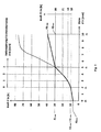
- a pressure force / thickness diagram is displayed.
- a further ordinate for the pressing force F1 is shown on the right-hand edge of the picture and a further abscissa for the representation of the deformation of the brush elements is shown on the upper edge of the picture.
- the further spring system is required, which prevents the pressing force acting on the mail piece from further increasing non-linearly with the thickness of the mail piece.
- the other spring system acts in this sense limiting the increase in the pressure force.
- the brush elements would be further deformed in such a case, ie d> 5 mm, so that the total pressure force acting on the mail piece further increases non-linearly.
- a curve corresponding to the above case was in Fig. 3 dashed lines.
- the pressing force F1 with which all the brush elements act on the mail piece in the sum, would exceed the pressing force F3 of the other spring system, which can lead to irreversible deformation of brush elements.
- the pressure force F3 should increase with a defined increase, because usually the gravity effect at a higher weight, especially for large-sized mail items, such as format B4, must be compensated.
- a recording medium 32 * or a bust body is mounted on the base plate 34 *.
Landscapes
- Engineering & Computer Science (AREA)
- Mechanical Engineering (AREA)
- Physics & Mathematics (AREA)
- General Physics & Mathematics (AREA)
- Motor Or Generator Current Collectors (AREA)
- Delivering By Means Of Belts And Rollers (AREA)
Abstract
Description
- Die Erfindung betrifft eine Andruckvorrichtung mit federelastischen Elementen, gemäß der im Oberbegriff des Patentanspruchs 1 angegebenen Art und ist anwendbar für alle Anordnungen, welche elastische Andruckelemente verwenden, die keine dauerhafte Verformung erfahren sollen. Die Erfindung gestattet es insbesondere eine Transport- oder Druckvorrichtung zu vereinfachen, die für den Einsatz in einem Postfrankiersystem bzw. in einer Frankiermaschine vorgesehen ist. Wenn nachfolgend von flachen Gütern gesprochen wird, sollen damit aber nicht Papierstreifen, Poststücke oder andere Waren ausgeschlossen werden, für welche die Gegendruckvorrichtung ebenfalls geeignet ist.
- Aus der deutschen Gebrauchsmusterschrift
DE 20 2007 019 194 U1 ist eine Vorrichtung zum Andrücken flacher Güter an ein Transportmodul bekannt, die ein Transportband-Bürste-System verwendet. Dieses System funktioniert für Poststücke, mit einer ausreichenden Dicke, wie z.B. für Briefe auch über einen längeren Zeitraum ausreichend gut. Die Andruckkraft wird durch einen Überhub zwischen Transportband und Bürstenelementen bei gleichzeitiger Bewegung des Transportbandes realisiert. Die Bürstenelemente weisen Halter auf. Die Halter sind in einem Bürstenkörper befestigt. Letzterer ist in einem Aufnahmeträger montiert. Ein weiterer aus derDE 20 2007 019 194 U1 , Fig. 4 bekannter Prototyp, weist ein vorgenannte Bürstenelemente aufweisendes erstes Federsystem und ein zweites Federsystem auf, das mit dem ersten mechanisch gekoppelt ist. Das zweite Federsystem besteht aus einer Basisplatte, die über Abstandsbolzen auf einer Bodenplatte und gegenüber der letzteren federnd befestigt ist. - Für das Andrücken werden Bürstenelemente als Federelemente verwendet, die eine nichtlinear wachsende Andruckkraft F1 erzeugen. Das zweite Federsystem drückt mit einer linear wachsenden Andruckkraft F2 den Aufnahmeträger mit den Bürstenelementen entgegen der Schwerkraft gegen das Transportband. Ein Überhub wird auch dann erzeugt, wenn sich kein flaches Gut zwischen dem Transportband und der Andruckvorrichtung befindet (Ruhezustand). Der Überhub ist so ausgelegt, dass auch bei auftretenden Bauteiltoleranzen der Andruckvorrichtung im Ruhezustand eine Andruckkraft an das Transportband mit Sicherheit vorhanden ist. Die Auslenkung der Andruckvorrichtung erfolgt durch Federkraft entgegen der Schwerkraft und wird durch Begrenzungsmittel auf den Überhub von ca. 2 mm begrenzt. Die Andruckkraft F2 ist dabei so groß, dass im Ruhezustand eine Überbeanspruchung und damit eine dauerhafte Verformung der Bürstenelemente der Andruckvorrichtung verursacht wird, wobei die Formel gilt:

- Die Federkraft F1 wird im Ruhezustand materialbedingt mit der Zeitdauer der Verformung immer geringer, was zu Transportproblemen bei sehr dünnen flachen Gütern führt, insbesondere bei Frankierstreifen.
- Die Aufgabe war zu lösen, eine Andruckvorrichtung mit federelastischen Elementen zu entwickeln, welche für Poststücke unterschiedlicher Dicke geeignet ist und über einen langen Zeitraum ohne Verformung der Bürstenelemente einen sicheren Transport speziell sehr dünner flacher Güter, insbesondere Frankierstreifen, gewährleistet.
- Die Aufgabe wird mit den Merkmalen des Patentanspruchs 1 gelöst.
- Es wurde erkannt, dass die Bürstenelemente eines Bürstenkörpers, die ein erstes Federsystem bilden, besonders gut zum Transport von dünnen flachen Gütern geeignet sind, wenn die Bürstenelemente im Ruhezustand der Andruckvorrichtung unverformt sind.
- Eine Andruckvorrichtung, die mit federelastischen Elementen, insbesondere Bürstenelementen ausgestattet ist, wird statt mit einem Einfach-Federsystem nun mit einem Doppel-Federsystem mechanisch gekoppelt, welches einerseits die notwendige Andruckkraft bereitstellt und andererseits auch die Andruckkraft so optimiert, dass eine bleibende Verformung der Bürstenelemente im Ruhezustand der Andruckvorrichtung verhindert wird. Die Bürstenelemente sind die federelastischen Elemente eines ersten Federsystems, die ab einer Kraft verformt werden, die einer minimalen Andruckkraft F1min des ersten Feder-systems entspricht. Deren Andruckkraft wächst nichtlinear mit wachsender Dicke der Güter, die im Betriebszustand vom Transportband entlang eines Transportpfades transportiert werden und zwischen das Transportband und die Andruckvorrichtung gelangen. Es wurde empirisch ermittelt, dass eine bleibende Verformung der Bürstenelemente im Ruhezustand verhindert wird, wenn die Bürstenelemente mit einer geringeren Andruckkraft als mit einer minimalen Andruckkraft F1 min des ersten Federsystems auf das Transportband einwirken. Im Ruhezustand der Andruckvorrichtung wirkt deshalb ein zweites Federsystem mit der Andruckkraft F2 über das erste Federsystem auf das Transportband ein, um diejenigen Kräfte aufzunehmen, welche die Bürstenelemente verformen könnten, wobei für die Andruckkräfte gilt:

- Die minimale Andruckkraft F2 des zweiten Federsystems wird dabei soweit niedriger gewählt, als die minimale Andruckkraft F1min des ersten Feder-systems, so dass sichergestellt ist, dass die im Ruhezustand der Andruckvorrichtung wirkende minimale Andruckkraft F2 auf das Transportband unterhalb der Summe der Verformungskräfte DB* aller Bürstenelemente B1*, B2*, ..., Bi*, ..., Bn* verbleibt:

- Im Ruhezustand der Andruckvorrichtung ist kein Gut im Transportweg vorhanden, im Unterschied zu deren Betriebszustand. Im Betriebszustand wird ein flaches Gut transportiert. Aufgrund der Dicke des flachen Gutes kommt es zu einer Auslenkung des Aufnahmeträgers in Richtung der Schwerkraft. Der Auslenkung des Aufnahmeträgers entgegen wirkt eine Federkraft. Letztere wird durch Begrenzungsmittel begrenzt, welche zwischen der Basisplatte und der Grundplatte angeordnet sind. Aufgrund der Begrenzung ist das zweite Federsystem vorgespannt. Weiterhin sind mindestens zwei erste Anschlagelemente vorgesehen, welche den Hub der Basisplatte zur Grundplatte in Richtung der Schwerkraft begrenzen. Aufgrund einer Federkonstanten R2 der Federkraft aller Druckfedern zusammen wächst die Andruckkraft F2 proportional mit der Auslenkung. Bei der Auslenkung wird ein Weg zurückgelegt, der durch die Anschlagelemente begrenzt ist. Der vorgenannte Weg entspricht einer durchschnittlichen Dicke des flachen Gutes (Poststückes). Dieser Weg wird als Hub bezeichnet.
- Wenn auch zunächst einzelne Bürstenelemente beim Eintreffen der Kante eines flachen Gutes und während dessen Transports verformt werden, dann überträgt sich deren Auslenkung in der Folge insgesamt auf die Auslenkung des Aufnahmeträgers bis zu einem vorbestimmten Hub von s1 = 2 mm. Die Andruckkraft F2 des zweiten Federsystems ist insgesamt niedriger, als die minimale Andruckkraft F1min des ersten Federsystems. Bei der mechanischen Kopplung beider Federsysteme tritt im Ruhezustand keinerlei Verformung der Bürstenelemente mehr auf, solange die Andruckkraft insgesamt unterhalb der Summe der Verformungkräfte Σ DB* bleibt. Bis zu einem Hub des Aufnahmeträgers in Schwerkraftrichtung entsprechend einer ersten Dicke eines flachen Gutes, beispielsweise eines Poststückes von bis zu 2 mm, wird nur die Andruckkraft F2 des zweiten Federsystems auf das Poststück wirksam. Bei dem Hub s1 = 2 mm des Aufnahmeträgers in Schwerkraftrichtung entsprechend der ersten Dicke eines Poststückes wird der erste Anschlag der Anordnung erreicht, der den Hub begrenzt, der zwischen der Basisplatte und der Grundplatte der Andruckvorrichtung auftreten kann. Aufgrund der Begrenzung des Hubes wirkt die Andruckkraft F1 des ersten Federsystems statt der Andruckkraft F2 des zweiten Federsystems. Die Andruckkraft F1 wächst aufgrund der Verformung der Bürstenelemente ab der minimalen Andruckkraft F1 min nichtlinear mit der Dicke des flachen Gutes an, solange nicht die minimale Andruckkraft F3min eines weitern dritten Federsystems erreicht ist. Auch Poststücke mittlerer Dicke können im Betriebszustand transportiert werden, ohne dass eine bleibende Verformung der Bürstenelemente auftritt, solange eine Andruckkraft des ersten Federsystems nicht überschritten wird, bei welcher die reversible Verformung in eine irreversible Verformung übergeht. Sie tritt bei den im Ausführungsbeispiel verwendeten Bürstenelementen bei der ersten Dicke eines flachen Gutes auf. Der weitere Anstieg der Andruckkraft mit der Dicke des flachen Gutes wird bei einer zweiten Dicke des flachen Gutes begrenzt. Bei dieser zweiten Dicke wurde eine optimale Andruckkraft F1opt empirisch ermittelt.
- Im Betriebszustand der Andruckvorrichtung wird für Poststücke ab der zweiten Dicke ein weiteres Federsystem wirksam, das mit einer minimalen Andruckkraft F3min = F1opt einwirkt, wenn die optimale Andruckkraft F1opt des ersten Federsystems erreicht wird. Die Andruckkraft wächst ab F3min weiter linear mit der Dicke des flachen Gutes an. Der Proportionalitätsfaktor wird als Federkonstante R3 bezeichnet und ist viel größer als die Federkonstante R2.
- Somit ergibt sich ein mechanisch gekoppeltes Doppel-Federsystem, das auf den Bürstenkörper einwirkt. Damit können dünne bis dicke flache Güter (Poststücke) transportiert werden, wobei für die Andruckkräfte gilt:

- Jedes der Bürstenelemente Bi* besteht aus einem Bündel von Bürstenhaaren bzw. -Borsten und weist im Andruckkraft/Dicke-Diagramm eine Nichtlinearität der Verformungskraft DBi* auf, die auf der zunehmenden Reibung der Bürstenhaare bzw. -Borsten untereinander bei deren Verformung beruht, wobei die Reibung mit deren Verformung zunimmt. Bei der optimalen Andruckkraft F1opt werden zwar Bürstenelemente im Betriebstzustand der Andruckvorrichtung kurzzeitig verformt, jedoch ohne dass die Verformung irreversibel ist. Vielmehr ist die Verformung noch reversibel.
- Vorteilhafte Weiterbildungen der Erfindung sind in den Unteransprüchen gekennzeichnet bzw. werden nachstehend zusammen mit der Beschreibung der bevorzugten Ausführung der Erfindung anhand der Figuren näher dargestellt.
- In der
Fig. 1 ist eine Vorderansicht der Andruckvorrichtung im Betriebszustand als Prinzipbild gezeigt. Ein weißer Pfeil zeigt in die Transportrichtung eines flachen Gutes 4. Der Bürstenkörper weist die Bürstenelemente B* = B1*, B2*, ..., Bi*, ..., Bn* auf. Die Bürstenelemente B1* und B2* sind angeschrägt, um das Eintreten vor allem eines dickeren Gutes in den Spalt zwischen dem Transportband 2 und der Andruckvorrichtung zu erleichtern. Der Aufnahmeträger 32* (Bürstenkörper) ist mit einem Doppel-Federsystem mechanisch gekoppelt. Das Doppel-Federsystem besteht aus den bereits bekannten Federelementen 37*, die zwischen einer Basisplatte 34* und einer Grundplatte 38* angeordnet sind, welche schon bisher dazu dienten, die Bürstenelemente an ein Transportband 2 anzudrücken und welche in der Summe eine Federkonstante R2 aufweisen sowie aus weiteren Federelementen 42*, die zwischen der Grundplatte 38* und dem Chassis 40* angeordnet sind und in der Summe eine Federkonstante R3 aufweisen. Die Federkonstante R2 der Federelemente 37* ist aber nun wesentlich niedriger gewählt, als bei der Vorgängerlösung gemäßDE 20 2007 019 194 U1 , so dass sichergestellt ist, dass im Ruhezustand der Druckvorrichtung die Andruckkräfte unterhalb der Verformungskraft der Bürstenelemente B* verbleiben. Das Federsystem ist mit den Federelementen 37* nun weicher gefedert, als das erste Federsystem mit den Bürstenelementen B* oder das weitere dritte Federsystem mit den Federelementen 42*. - Die
Figur 1 zeigt, dass die Basisplatte 34* in Schwerkraftrichtung ausgelenkt wurde. Der Auslenkung der Basisplatte 34* wirkt eine Federkraft entgegen, welche durch mindestens zwei Druckfedern 37* aufgebracht wird. Die vorgenannte Federkraft wird durch Begrenzungsmittel begrenzt, bestehend beispielsweise jeweils aus einer Sicherungsscheibe 36* und Abstandsbolzen 35*, wobei die Basisplatte 34* eine Öffnung zur Hindurchführung des Abstandsbolzens 35* aufweist. Aufgrund der Begrenzung ist das zweite Federsystem vorgespannt. Die Federelemente 37* wurden entsprechend der Dicke des flachen Gutes 4 zusammengedrückt, so dass Sicherungsscheibe 36* und die Basisplatte 34* voneinander beabstandet sind. - Mindestens zwei Anschlagelemente 341* sind an der Basisplatte 34* montiert und entsprechend zur Begrenzung des Hubes in Schwerkraftrichtung so geformt, dass ein Anschlag an der Grundplatte 38* erreicht wird, wenn die Dicke des flachen Gutes 4 - in der gezeigten Weise - eine erste Dicke erreicht oder überschreitet.
- Mindestens zwei Begrenzungselemente 41* sind am Chassis 40* angeordnet und begrenzen die Bewegung der Grundplatte 38* im Ruhezustand der Andruckvorrichtung und im - in der
Figur 1 dargestellten - Betriebzustand für dünne flache Güter. Damit wird die Wirkung des weiteren Federsystems entgegen der Schwerkraftrichtung begrenzt. - Alternativ zu einem der ersten Anschlagselemente 341*, die an der Basisplatte angebracht sind, kann ein erstes Anschlagselement - in einer nicht gezeigten Variante - an der Grundplatte 38* montiert sein und an der Basisplatte 34* anschlagen, wenn die Gutdicke die erste Dicke erreicht oder überschreitet.
- In der
Fig. 2 wird die Deformation eines Bürstenelements Bi+1* im Vergleich mit einem Bürstenelement Bi* dargestellt. Die Deformation von Bürstenelementen tritt auf, wenn ein dickeres als das in derFigur 1 gezeigte flache Gut 4 angedrückt wird. - Das - in der
Figur 1 gezeigte - weitere Federsystem ist zwischen der Grundplatte 38* und dem Chassis 40* montiert und kann erst dann wirksam werden, wenn die Andruckkraft über einen Schwellwert F1opt ansteigt, was eine entsprechende Dicke des flachen Gutes voraussetzt. - Vor der Druckvorrichtung ist eine Schleuse 42* mit einer Durchlassöffnung für Poststücke vorgesehen, welche die Dicke eines durchgelassenen Gutes auf eine definierte maximale Dicke begrenzt, beispielsweise auf 10 mm.
- In der
Fig. 3 wird ein Andruckkraft/Dicken-Diagramm dargestellt. Der Anstieg der dargestellten Kurve der Andruckkraft F2 beträgt m2 = (F1min - F2min) / (d1 - d0) und ist gleich der Federkonstanten R2. Der Anstieg der dargestellten Kurve der Andruckkraft F3 beträgt m3 = (F3max - F1opt) / (d3 - d2) und ist gleich der Federkonstanten R3. Bei dem vorgenannten Ausführungsbeispiel beträgt F3min = F1opt = 30 N. In der Praxis wird dies durch die Federkraft von vier Druckfedern 42* erreicht. - Innerhalb des vorgenannten Andruckkraft/Dicken-Diagramms ist am rechten Bildrand eine weitere Ordinate für die Andruckkraft F1 und am oberen Bildrand eine weitere Abzisse für die Darstellung der Deformierung der Bürstenelemente gezeigt. Nach dem Anschlagen mindestens des erstes Anschlagselements 341* ist bei der im Ausführungsbeispiel verwendeten Bürste allein eine Deformierung der Bürstenelemente bis zum Wert D = 3 mm möglich. Es ist ersichtlich, dass die auf das Poststück wirkende Andruckkraft mit der Deformierung der Bürstenelemente weiter nichtlinear anwächst.
- Weil besonders bei dickeren Gütern der Anstieg der Kurve unter der Wirkung der von den Bürstenelementen aufgebrachten Andruckkraft F1 zu steil werden würde, ist das weitere Federsystem erforderlich, welches verhindert, dass die auf das Poststück wirkende Andruckkraft mit der Dicke des Poststückes weiter nichtlinear anwächst. Das weitere Federsystem wirkt in diesem Sinne begrenzend für den Anstieg der Andruckkraft. Ohne die Verwendung des weiteren Federsystems mit der Federkonstanten R3 würden die Bürstenelemente in einem solchen Fall, d.h. d > 5 mm, weiter verformt werden, so dass die auf das Poststück insgesamt wirkende Andruckkraft weiter nichtlinear anwächst. Eine Kurve entsprechend dem vorgenannten Fall wurde in der
Fig. 3 gestrichelt eingezeichnet. - Die Andruckkraft F1, mit welcher alle Bürstenelemente in der Summe auf das Poststück einwirken, würde die Andruckkraft F3 des weiteren Federsystems übersteigen, was zu einer irreversiblen Verformung von Bürstenelementen führen kann. Andererseits sollte die Andruckkraft F3 mit einem definierten Anstieg ansteigen, weil in der Regel die Schwerkraftwirkung bei einem höheren Gewicht, insbesondere bei großformatigen Poststücken, wie zum Beispiel vom Format B4, kompensiert werden muss.
- Es ist vorgesehen, auf der Basisplatte 34* ein Aufnahmeträger 32* oder ein Büstenkörper montiert ist.
- Die Erfindung ist nicht auf die vorliegend erläuterte Ausführungsform beschränkt, da offensichtlich weitere andere Ausführungen der Erfindung entwickelt bzw. eingesetzt werden können, die - vom gleichen Grundgedanken der Erfindung ausgehend - von den anliegenden Schutzansprüchen umfasst werden.
Claims (6)
- Andruckvorrichtung mit federelastischen Elementen, insbesondere Bürstenelementen eines Bürstenkörpers, mit welchen ein Federsystem mechanisch gekoppelt ist, welches eine Anzahl an Federelementen (37*) aufweist, die zwischen einer Basisplatte (34*) und einer Grundplatte (38*) angeordnet sind, dadurch gekennzeichnet, dass die Bürstenelemente (B1*, B2*, ..., Bi*, ..., Bn*) der Andruckvorrichtung mit einem Doppel-Federsystem mechanisch gekoppelt sind, dass das Doppel-Federsystem aus dem vorgenannten Federsystem und einem weiteren mit dem vorgenannten Federsystem mechanisch gekoppelten Federsystem besteht, wobei das vorgenannten Federsystem insgesamt im Ruhezustand auf eine vorbestimmte minimale Andruckkraft F2min vorgespannt ist und im Betriebszustand für flache Güter bis zu einer ersten Dicke eine mit der Dicke linear ansteigende Andruck-kraft F2 ausübt, wobei im Ruhezustand eine geringere Andruckkraft ausgeübt wird, als durch die Bürstenelemente bereitgestellt wird, dass mindestens zwei erste Anschlagelemente (341*) vorgesehen sind, die den Hub der Basisplatte (34*) zur Grundplatte (38*) in Richtung der Schwerkraft begrenzen, wobei nach dem Anschlagen der Anschlagelemente (341*) die Bürstenelemente in der Summe eine minimale Andruckkraft F1 min bereitstellen, welche der Summe der Verformungskräfte DB der Bürstenelemente im Ruhezustand der Andruckvor-richtung entspricht, und wobei die Bürstenelemente im Betriebszustand für flache Güter ab der ersten Dicke bis einer zweiten Dicke eine nichtlinear ansteigende Andruckkraft bis zu einer optimalen Andruckkraft F1opt auf das flache Gut ausüben und dass das weitere Federsystem insgesamt auf eine vorbestimmte Andruckkraft F3min vorgespannt ist, welche gleich der optimalen Andruckkraft F1opt der Bürstenelemente ist und im Betriebszustand für flache Güter ab einer zweiten Dicke eine mit der Dicke linear ansteigende Andruckkraft F3 ausübt, wobei für die Andruckkräfte gilt:

- Andruckvorrichtung, nach Anspruch 1, dadurch gekennzeichnet, dass das Anschlagelement (341*) an der Basisplatte (34*) montiert und entsprechend zur Begrenzung des Hubes so geformt ist, dass ein Anschlag an der Grundplatte (38*) erreicht wird.
- Andruckvorrichtung, nach Anspruch 1, dadurch gekennzeichnet, dass das mit dem vorgenannten Federsystem mechanisch gekoppelte weitere Federsystem aus weiteren Federelementen (42*) besteht, die zwischen der Grundplatte (38*) und einem Chassis (40*) angeordnet sind.
- Andruckvorrichtung, nach Anspruch 3, dadurch gekennzeichnet, dass ein an dem Chassis (40*) angeordnetes Begrenzungselement (41*) die Bewegung der Grundplatte (38*) und somit die Wirkung des weiteren Feder-systems entgegen der Schwerkraftrichtung begrenzt, wodurch das weitere Federsystem auf die vorbestimmte Andruckkraft F3min vorgespannt wird.
- Andruckvorrichtung, nach Anspruch 1, dadurch gekennzeichnet, dass für flache Güter ab der ersten Dicke von d1 = 2 mm der Hub der Basisplatte (34*) zur Grundplatte (38*) der Andruckvorrichtung begrenzt wird.
- Andruckvorrichtung, nach Anspruch 1, dadurch gekennzeichnet, dass auf der Basisplatte (34*) ein Aufnahmeträger (32*) oder ein Büstenkörper montiert ist.
Applications Claiming Priority (1)
| Application Number | Priority Date | Filing Date | Title |
|---|---|---|---|
| DE201120109208 DE202011109208U1 (de) | 2011-12-14 | 2011-12-14 | Andruckvorrichtung mit federelastischen Elementen |
Publications (3)
| Publication Number | Publication Date |
|---|---|
| EP2604557A2 true EP2604557A2 (de) | 2013-06-19 |
| EP2604557A3 EP2604557A3 (de) | 2014-08-20 |
| EP2604557B1 EP2604557B1 (de) | 2016-03-30 |
Family
ID=45756686
Family Applications (1)
| Application Number | Title | Priority Date | Filing Date |
|---|---|---|---|
| EP12007761.5A Active EP2604557B1 (de) | 2011-12-14 | 2012-11-16 | Andruckvorrichtung mit federelastischen Elementen |
Country Status (3)
| Country | Link |
|---|---|
| EP (1) | EP2604557B1 (de) |
| CA (1) | CA2797331C (de) |
| DE (1) | DE202011109208U1 (de) |
Families Citing this family (6)
| Publication number | Priority date | Publication date | Assignee | Title |
|---|---|---|---|---|
| DE202013005632U1 (de) | 2013-06-21 | 2013-07-04 | Francotyp-Postalia Gmbh | Druckergerät |
| DE102012014901A1 (de) | 2012-07-18 | 2014-05-15 | Francotyp-Postalia Gmbh | Andruckvorrichtung für flache Gegenstände an ein umlaufendes Transportband |
| US9010755B2 (en) | 2012-07-18 | 2015-04-21 | Francotyp-Postalia Gmbh | Printer apparatus |
| EP2688047B1 (de) | 2012-07-18 | 2015-05-06 | Francotyp-Postalia GmbH | Druckergerät |
| KR101503260B1 (ko) * | 2013-07-23 | 2015-03-17 | 주식회사 웰텍 | 전자 인영 시스템의 우편물 반송장치 및 반송방법 |
| DE202013105555U1 (de) | 2013-12-06 | 2014-01-13 | Francotyp-Postalia Gmbh | Druckergerät |
Citations (1)
| Publication number | Priority date | Publication date | Assignee | Title |
|---|---|---|---|---|
| DE202007019194U1 (de) | 2007-12-17 | 2011-02-10 | Francotyp-Postalia Gmbh | Vorrichtung zum Andrücken flacher Güter an ein Transportmodul |
Family Cites Families (2)
| Publication number | Priority date | Publication date | Assignee | Title |
|---|---|---|---|---|
| DE102007007813B3 (de) * | 2007-02-16 | 2008-01-17 | Siemens Ag | Vorrichtung und Verfahren zum Vereinzeln von flachen Gegenständen |
| AU2010222187B2 (en) * | 2009-03-09 | 2014-05-22 | Ezawa Jimuki Co., Ltd. | Device for feeding sheets, brochures, or the like, and system for sorting documents to be dispatched |
-
2011
- 2011-12-14 DE DE201120109208 patent/DE202011109208U1/de not_active Expired - Lifetime
-
2012
- 2012-11-16 EP EP12007761.5A patent/EP2604557B1/de active Active
- 2012-12-03 CA CA2797331A patent/CA2797331C/en active Active
Patent Citations (1)
| Publication number | Priority date | Publication date | Assignee | Title |
|---|---|---|---|---|
| DE202007019194U1 (de) | 2007-12-17 | 2011-02-10 | Francotyp-Postalia Gmbh | Vorrichtung zum Andrücken flacher Güter an ein Transportmodul |
Also Published As
| Publication number | Publication date |
|---|---|
| EP2604557A3 (de) | 2014-08-20 |
| CA2797331A1 (en) | 2013-06-14 |
| DE202011109208U1 (de) | 2012-01-24 |
| EP2604557B1 (de) | 2016-03-30 |
| CA2797331C (en) | 2016-06-14 |
Similar Documents
| Publication | Publication Date | Title |
|---|---|---|
| EP2604557B1 (de) | Andruckvorrichtung mit federelastischen Elementen | |
| Schieferdecker et al. | Energiemanagement-Tools | |
| DE68903935T2 (de) | Blattzufuehrung. | |
| CH382477A (de) | Zähleinrichtung | |
| DE69207630T2 (de) | Bogenfördergerät | |
| Iancu et al. | Rashomon in Bukarest | |
| Lüftl et al. | Praxisbegleitung | |
| Küppers | Einführung in die Informatik | |
| Engeler et al. | Planet49: Neues vom EuGH zu Cookies, Tracking und ePrivacy-Starke Einwilligung, schwacher Datenschutz? | |
| EP0421138B1 (de) | Beschichtungsmaschine für Siebdruckgewebe | |
| DE102873C (de) | ||
| Abberger et al. | Auswertung der Sonderfragen zur Corona-Pandemie in den KOF Konjunkturumfragen | |
| Hierstetter | Handhabbarkeit und Evaluierung Europäischer Richtlinien im Bereich der direkten Steuern. | |
| Kracke et al. | individuelle Förderung | |
| DE2221857C3 (de) | Folienfaltvorrichtung | |
| Beneken | 2.1 Kopfarbeit | |
| AT235873B (de) | Druckeinrichtung zum Anbringen von Kennungen auf Postsendungen | |
| DE134780C (de) | ||
| AT202573B (de) | Elektrisch angetriebene Einzieh- oder Freigabevorrichtung für Blätter bei Schreib-, Rechen-, Buchungsmaschinen od. dgl. | |
| DE217483C (de) | ||
| DE102023120664A1 (de) | Vorrichtung zum Fangen und/oder Beseitigen von Insekten | |
| DE975418C (de) | Andrueckwalze zum Einziehen und Andruecken der Schreibblaetter in Schreibmaschinen gegen die Schreibwalze | |
| DE976219C (de) | Farbbandabdeckeinrichtung | |
| DE549843C (de) | Druckschablonensystem fuer Adressendruckmaschinen | |
| Orlando et al. | Beobachtungen einer Projektarbeit mit Anfängern. Studierende im ersten Studienjahr suchen selbstständig nach Antworten zu ihren persönlichen Deutschlandfragen. |
Legal Events
| Date | Code | Title | Description |
|---|---|---|---|
| PUAI | Public reference made under article 153(3) epc to a published international application that has entered the european phase |
Free format text: ORIGINAL CODE: 0009012 |
|
| AK | Designated contracting states |
Kind code of ref document: A2 Designated state(s): AL AT BE BG CH CY CZ DE DK EE ES FI FR GB GR HR HU IE IS IT LI LT LU LV MC MK MT NL NO PL PT RO RS SE SI SK SM TR |
|
| AX | Request for extension of the european patent |
Extension state: BA ME |
|
| PUAL | Search report despatched |
Free format text: ORIGINAL CODE: 0009013 |
|
| AK | Designated contracting states |
Kind code of ref document: A3 Designated state(s): AL AT BE BG CH CY CZ DE DK EE ES FI FR GB GR HR HU IE IS IT LI LT LU LV MC MK MT NL NO PL PT RO RS SE SI SK SM TR |
|
| AX | Request for extension of the european patent |
Extension state: BA ME |
|
| RIC1 | Information provided on ipc code assigned before grant |
Ipc: G07B 17/00 20060101ALI20140714BHEP Ipc: B65H 5/02 20060101AFI20140714BHEP |
|
| 17P | Request for examination filed |
Effective date: 20141203 |
|
| RBV | Designated contracting states (corrected) |
Designated state(s): AL AT BE BG CH CY CZ DE DK EE ES FI FR GB GR HR HU IE IS IT LI LT LU LV MC MK MT NL NO PL PT RO RS SE SI SK SM TR |
|
| RAP1 | Party data changed (applicant data changed or rights of an application transferred) |
Owner name: FRANCOTYP-POSTALIA GMBH |
|
| GRAP | Despatch of communication of intention to grant a patent |
Free format text: ORIGINAL CODE: EPIDOSNIGR1 |
|
| INTG | Intention to grant announced |
Effective date: 20151124 |
|
| GRAS | Grant fee paid |
Free format text: ORIGINAL CODE: EPIDOSNIGR3 |
|
| GRAA | (expected) grant |
Free format text: ORIGINAL CODE: 0009210 |
|
| AK | Designated contracting states |
Kind code of ref document: B1 Designated state(s): AL AT BE BG CH CY CZ DE DK EE ES FI FR GB GR HR HU IE IS IT LI LT LU LV MC MK MT NL NO PL PT RO RS SE SI SK SM TR |
|
| REG | Reference to a national code |
Ref country code: GB Ref legal event code: FG4D Free format text: NOT ENGLISH |
|
| REG | Reference to a national code |
Ref country code: CH Ref legal event code: EP |
|
| REG | Reference to a national code |
Ref country code: AT Ref legal event code: REF Ref document number: 785128 Country of ref document: AT Kind code of ref document: T Effective date: 20160415 |
|
| REG | Reference to a national code |
Ref country code: IE Ref legal event code: FG4D Free format text: LANGUAGE OF EP DOCUMENT: GERMAN |
|
| REG | Reference to a national code |
Ref country code: DE Ref legal event code: R096 Ref document number: 502012006479 Country of ref document: DE |
|
| REG | Reference to a national code |
Ref country code: SE Ref legal event code: TRGR |
|
| REG | Reference to a national code |
Ref country code: NL Ref legal event code: FP |
|
| REG | Reference to a national code |
Ref country code: LT Ref legal event code: MG4D |
|
| PG25 | Lapsed in a contracting state [announced via postgrant information from national office to epo] |
Ref country code: HR Free format text: LAPSE BECAUSE OF FAILURE TO SUBMIT A TRANSLATION OF THE DESCRIPTION OR TO PAY THE FEE WITHIN THE PRESCRIBED TIME-LIMIT Effective date: 20160330 Ref country code: FI Free format text: LAPSE BECAUSE OF FAILURE TO SUBMIT A TRANSLATION OF THE DESCRIPTION OR TO PAY THE FEE WITHIN THE PRESCRIBED TIME-LIMIT Effective date: 20160330 Ref country code: NO Free format text: LAPSE BECAUSE OF FAILURE TO SUBMIT A TRANSLATION OF THE DESCRIPTION OR TO PAY THE FEE WITHIN THE PRESCRIBED TIME-LIMIT Effective date: 20160630 Ref country code: GR Free format text: LAPSE BECAUSE OF FAILURE TO SUBMIT A TRANSLATION OF THE DESCRIPTION OR TO PAY THE FEE WITHIN THE PRESCRIBED TIME-LIMIT Effective date: 20160701 |
|
| PG25 | Lapsed in a contracting state [announced via postgrant information from national office to epo] |
Ref country code: LV Free format text: LAPSE BECAUSE OF FAILURE TO SUBMIT A TRANSLATION OF THE DESCRIPTION OR TO PAY THE FEE WITHIN THE PRESCRIBED TIME-LIMIT Effective date: 20160330 Ref country code: LT Free format text: LAPSE BECAUSE OF FAILURE TO SUBMIT A TRANSLATION OF THE DESCRIPTION OR TO PAY THE FEE WITHIN THE PRESCRIBED TIME-LIMIT Effective date: 20160330 Ref country code: RS Free format text: LAPSE BECAUSE OF FAILURE TO SUBMIT A TRANSLATION OF THE DESCRIPTION OR TO PAY THE FEE WITHIN THE PRESCRIBED TIME-LIMIT Effective date: 20160330 |
|
| PG25 | Lapsed in a contracting state [announced via postgrant information from national office to epo] |
Ref country code: PL Free format text: LAPSE BECAUSE OF FAILURE TO SUBMIT A TRANSLATION OF THE DESCRIPTION OR TO PAY THE FEE WITHIN THE PRESCRIBED TIME-LIMIT Effective date: 20160330 Ref country code: IS Free format text: LAPSE BECAUSE OF FAILURE TO SUBMIT A TRANSLATION OF THE DESCRIPTION OR TO PAY THE FEE WITHIN THE PRESCRIBED TIME-LIMIT Effective date: 20160730 Ref country code: EE Free format text: LAPSE BECAUSE OF FAILURE TO SUBMIT A TRANSLATION OF THE DESCRIPTION OR TO PAY THE FEE WITHIN THE PRESCRIBED TIME-LIMIT Effective date: 20160330 |
|
| REG | Reference to a national code |
Ref country code: FR Ref legal event code: PLFP Year of fee payment: 5 |
|
| PG25 | Lapsed in a contracting state [announced via postgrant information from national office to epo] |
Ref country code: ES Free format text: LAPSE BECAUSE OF FAILURE TO SUBMIT A TRANSLATION OF THE DESCRIPTION OR TO PAY THE FEE WITHIN THE PRESCRIBED TIME-LIMIT Effective date: 20160330 Ref country code: SM Free format text: LAPSE BECAUSE OF FAILURE TO SUBMIT A TRANSLATION OF THE DESCRIPTION OR TO PAY THE FEE WITHIN THE PRESCRIBED TIME-LIMIT Effective date: 20160330 Ref country code: RO Free format text: LAPSE BECAUSE OF FAILURE TO SUBMIT A TRANSLATION OF THE DESCRIPTION OR TO PAY THE FEE WITHIN THE PRESCRIBED TIME-LIMIT Effective date: 20160330 Ref country code: CZ Free format text: LAPSE BECAUSE OF FAILURE TO SUBMIT A TRANSLATION OF THE DESCRIPTION OR TO PAY THE FEE WITHIN THE PRESCRIBED TIME-LIMIT Effective date: 20160330 Ref country code: PT Free format text: LAPSE BECAUSE OF FAILURE TO SUBMIT A TRANSLATION OF THE DESCRIPTION OR TO PAY THE FEE WITHIN THE PRESCRIBED TIME-LIMIT Effective date: 20160801 Ref country code: SK Free format text: LAPSE BECAUSE OF FAILURE TO SUBMIT A TRANSLATION OF THE DESCRIPTION OR TO PAY THE FEE WITHIN THE PRESCRIBED TIME-LIMIT Effective date: 20160330 |
|
| REG | Reference to a national code |
Ref country code: DE Ref legal event code: R097 Ref document number: 502012006479 Country of ref document: DE |
|
| PG25 | Lapsed in a contracting state [announced via postgrant information from national office to epo] |
Ref country code: DK Free format text: LAPSE BECAUSE OF FAILURE TO SUBMIT A TRANSLATION OF THE DESCRIPTION OR TO PAY THE FEE WITHIN THE PRESCRIBED TIME-LIMIT Effective date: 20160330 |
|
| PLBE | No opposition filed within time limit |
Free format text: ORIGINAL CODE: 0009261 |
|
| STAA | Information on the status of an ep patent application or granted ep patent |
Free format text: STATUS: NO OPPOSITION FILED WITHIN TIME LIMIT |
|
| PG25 | Lapsed in a contracting state [announced via postgrant information from national office to epo] |
Ref country code: BE Free format text: LAPSE BECAUSE OF NON-PAYMENT OF DUE FEES Effective date: 20161130 |
|
| 26N | No opposition filed |
Effective date: 20170103 |
|
| PG25 | Lapsed in a contracting state [announced via postgrant information from national office to epo] |
Ref country code: SI Free format text: LAPSE BECAUSE OF FAILURE TO SUBMIT A TRANSLATION OF THE DESCRIPTION OR TO PAY THE FEE WITHIN THE PRESCRIBED TIME-LIMIT Effective date: 20160330 |
|
| REG | Reference to a national code |
Ref country code: IE Ref legal event code: MM4A |
|
| PG25 | Lapsed in a contracting state [announced via postgrant information from national office to epo] |
Ref country code: LU Free format text: LAPSE BECAUSE OF NON-PAYMENT OF DUE FEES Effective date: 20161130 |
|
| REG | Reference to a national code |
Ref country code: FR Ref legal event code: PLFP Year of fee payment: 6 |
|
| PG25 | Lapsed in a contracting state [announced via postgrant information from national office to epo] |
Ref country code: IE Free format text: LAPSE BECAUSE OF NON-PAYMENT OF DUE FEES Effective date: 20161116 |
|
| REG | Reference to a national code |
Ref country code: BE Ref legal event code: MM Effective date: 20161130 |
|
| PG25 | Lapsed in a contracting state [announced via postgrant information from national office to epo] |
Ref country code: HU Free format text: LAPSE BECAUSE OF FAILURE TO SUBMIT A TRANSLATION OF THE DESCRIPTION OR TO PAY THE FEE WITHIN THE PRESCRIBED TIME-LIMIT; INVALID AB INITIO Effective date: 20121116 Ref country code: CY Free format text: LAPSE BECAUSE OF FAILURE TO SUBMIT A TRANSLATION OF THE DESCRIPTION OR TO PAY THE FEE WITHIN THE PRESCRIBED TIME-LIMIT Effective date: 20160330 |
|
| PG25 | Lapsed in a contracting state [announced via postgrant information from national office to epo] |
Ref country code: TR Free format text: LAPSE BECAUSE OF FAILURE TO SUBMIT A TRANSLATION OF THE DESCRIPTION OR TO PAY THE FEE WITHIN THE PRESCRIBED TIME-LIMIT Effective date: 20160330 Ref country code: MK Free format text: LAPSE BECAUSE OF FAILURE TO SUBMIT A TRANSLATION OF THE DESCRIPTION OR TO PAY THE FEE WITHIN THE PRESCRIBED TIME-LIMIT Effective date: 20160330 Ref country code: MC Free format text: LAPSE BECAUSE OF FAILURE TO SUBMIT A TRANSLATION OF THE DESCRIPTION OR TO PAY THE FEE WITHIN THE PRESCRIBED TIME-LIMIT Effective date: 20160330 |
|
| PG25 | Lapsed in a contracting state [announced via postgrant information from national office to epo] |
Ref country code: BG Free format text: LAPSE BECAUSE OF FAILURE TO SUBMIT A TRANSLATION OF THE DESCRIPTION OR TO PAY THE FEE WITHIN THE PRESCRIBED TIME-LIMIT Effective date: 20160330 |
|
| PG25 | Lapsed in a contracting state [announced via postgrant information from national office to epo] |
Ref country code: MT Free format text: LAPSE BECAUSE OF FAILURE TO SUBMIT A TRANSLATION OF THE DESCRIPTION OR TO PAY THE FEE WITHIN THE PRESCRIBED TIME-LIMIT Effective date: 20160330 |
|
| PG25 | Lapsed in a contracting state [announced via postgrant information from national office to epo] |
Ref country code: AL Free format text: LAPSE BECAUSE OF FAILURE TO SUBMIT A TRANSLATION OF THE DESCRIPTION OR TO PAY THE FEE WITHIN THE PRESCRIBED TIME-LIMIT Effective date: 20160330 |
|
| P01 | Opt-out of the competence of the unified patent court (upc) registered |
Effective date: 20230807 |
|
| REG | Reference to a national code |
Ref country code: CH Ref legal event code: U11 Free format text: ST27 STATUS EVENT CODE: U-0-0-U10-U11 (AS PROVIDED BY THE NATIONAL OFFICE) Effective date: 20251201 |
|
| PGFP | Annual fee paid to national office [announced via postgrant information from national office to epo] |
Ref country code: NL Payment date: 20251119 Year of fee payment: 14 |
|
| PGFP | Annual fee paid to national office [announced via postgrant information from national office to epo] |
Ref country code: DE Payment date: 20251006 Year of fee payment: 14 |
|
| PGFP | Annual fee paid to national office [announced via postgrant information from national office to epo] |
Ref country code: GB Payment date: 20251121 Year of fee payment: 14 |
|
| PGFP | Annual fee paid to national office [announced via postgrant information from national office to epo] |
Ref country code: AT Payment date: 20251120 Year of fee payment: 14 |
|
| PGFP | Annual fee paid to national office [announced via postgrant information from national office to epo] |
Ref country code: IT Payment date: 20251125 Year of fee payment: 14 |
|
| PGFP | Annual fee paid to national office [announced via postgrant information from national office to epo] |
Ref country code: FR Payment date: 20251125 Year of fee payment: 14 |
|
| PGFP | Annual fee paid to national office [announced via postgrant information from national office to epo] |
Ref country code: CH Payment date: 20251201 Year of fee payment: 14 Ref country code: SE Payment date: 20251119 Year of fee payment: 14 |