EP2604480A1 - Mechanische Lenkverriegelung - Google Patents
Mechanische Lenkverriegelung Download PDFInfo
- Publication number
- EP2604480A1 EP2604480A1 EP12006733.5A EP12006733A EP2604480A1 EP 2604480 A1 EP2604480 A1 EP 2604480A1 EP 12006733 A EP12006733 A EP 12006733A EP 2604480 A1 EP2604480 A1 EP 2604480A1
- Authority
- EP
- European Patent Office
- Prior art keywords
- cobblestone
- extension
- lock cylinder
- counter
- lock
- Prior art date
- Legal status (The legal status is an assumption and is not a legal conclusion. Google has not performed a legal analysis and makes no representation as to the accuracy of the status listed.)
- Granted
Links
Images



Classifications
-
- B—PERFORMING OPERATIONS; TRANSPORTING
- B60—VEHICLES IN GENERAL
- B60R—VEHICLES, VEHICLE FITTINGS, OR VEHICLE PARTS, NOT OTHERWISE PROVIDED FOR
- B60R25/00—Fittings or systems for preventing or indicating unauthorised use or theft of vehicles
- B60R25/01—Fittings or systems for preventing or indicating unauthorised use or theft of vehicles operating on vehicle systems or fittings, e.g. on doors, seats or windscreens
- B60R25/02—Fittings or systems for preventing or indicating unauthorised use or theft of vehicles operating on vehicle systems or fittings, e.g. on doors, seats or windscreens operating on the steering mechanism
- B60R25/021—Fittings or systems for preventing or indicating unauthorised use or theft of vehicles operating on vehicle systems or fittings, e.g. on doors, seats or windscreens operating on the steering mechanism restraining movement of the steering column or steering wheel hub, e.g. restraining means controlled by ignition switch
- B60R25/0211—Fittings or systems for preventing or indicating unauthorised use or theft of vehicles operating on vehicle systems or fittings, e.g. on doors, seats or windscreens operating on the steering mechanism restraining movement of the steering column or steering wheel hub, e.g. restraining means controlled by ignition switch comprising a locking member radially and linearly moved towards the steering column
- B60R25/02115—Fittings or systems for preventing or indicating unauthorised use or theft of vehicles operating on vehicle systems or fittings, e.g. on doors, seats or windscreens operating on the steering mechanism restraining movement of the steering column or steering wheel hub, e.g. restraining means controlled by ignition switch comprising a locking member radially and linearly moved towards the steering column key actuated
- B60R25/02118—Fittings or systems for preventing or indicating unauthorised use or theft of vehicles operating on vehicle systems or fittings, e.g. on doors, seats or windscreens operating on the steering mechanism restraining movement of the steering column or steering wheel hub, e.g. restraining means controlled by ignition switch comprising a locking member radially and linearly moved towards the steering column key actuated with linear bolt motion parallel to the lock axis
- B60R25/02121—Fittings or systems for preventing or indicating unauthorised use or theft of vehicles operating on vehicle systems or fittings, e.g. on doors, seats or windscreens operating on the steering mechanism restraining movement of the steering column or steering wheel hub, e.g. restraining means controlled by ignition switch comprising a locking member radially and linearly moved towards the steering column key actuated with linear bolt motion parallel to the lock axis comprising safety devices avoiding locking until removal of the key
-
- B—PERFORMING OPERATIONS; TRANSPORTING
- B60—VEHICLES IN GENERAL
- B60R—VEHICLES, VEHICLE FITTINGS, OR VEHICLE PARTS, NOT OTHERWISE PROVIDED FOR
- B60R25/00—Fittings or systems for preventing or indicating unauthorised use or theft of vehicles
- B60R25/01—Fittings or systems for preventing or indicating unauthorised use or theft of vehicles operating on vehicle systems or fittings, e.g. on doors, seats or windscreens
- B60R25/02—Fittings or systems for preventing or indicating unauthorised use or theft of vehicles operating on vehicle systems or fittings, e.g. on doors, seats or windscreens operating on the steering mechanism
- B60R25/021—Fittings or systems for preventing or indicating unauthorised use or theft of vehicles operating on vehicle systems or fittings, e.g. on doors, seats or windscreens operating on the steering mechanism restraining movement of the steering column or steering wheel hub, e.g. restraining means controlled by ignition switch
- B60R25/0211—Fittings or systems for preventing or indicating unauthorised use or theft of vehicles operating on vehicle systems or fittings, e.g. on doors, seats or windscreens operating on the steering mechanism restraining movement of the steering column or steering wheel hub, e.g. restraining means controlled by ignition switch comprising a locking member radially and linearly moved towards the steering column
- B60R25/02115—Fittings or systems for preventing or indicating unauthorised use or theft of vehicles operating on vehicle systems or fittings, e.g. on doors, seats or windscreens operating on the steering mechanism restraining movement of the steering column or steering wheel hub, e.g. restraining means controlled by ignition switch comprising a locking member radially and linearly moved towards the steering column key actuated
- B60R25/02126—Fittings or systems for preventing or indicating unauthorised use or theft of vehicles operating on vehicle systems or fittings, e.g. on doors, seats or windscreens operating on the steering mechanism restraining movement of the steering column or steering wheel hub, e.g. restraining means controlled by ignition switch comprising a locking member radially and linearly moved towards the steering column key actuated with linear bolt motion perpendicular to the lock axis
- B60R25/02128—Fittings or systems for preventing or indicating unauthorised use or theft of vehicles operating on vehicle systems or fittings, e.g. on doors, seats or windscreens operating on the steering mechanism restraining movement of the steering column or steering wheel hub, e.g. restraining means controlled by ignition switch comprising a locking member radially and linearly moved towards the steering column key actuated with linear bolt motion perpendicular to the lock axis comprising safety devices avoiding locking until removal of the key
- B60R25/02131—Fittings or systems for preventing or indicating unauthorised use or theft of vehicles operating on vehicle systems or fittings, e.g. on doors, seats or windscreens operating on the steering mechanism restraining movement of the steering column or steering wheel hub, e.g. restraining means controlled by ignition switch comprising a locking member radially and linearly moved towards the steering column key actuated with linear bolt motion perpendicular to the lock axis comprising safety devices avoiding locking until removal of the key by using an axially slidable lock cylinder
Definitions
- the invention relates to a mechanical steering lock for a vehicle having a key cylinder which can be actuated according to the preamble of claim 1.
- the invention is therefore an object of the invention to provide a mechanical steering lock for a vehicle available, which allows a large rotation angle of the lock cylinder of 85 ° and more, is inexpensive to manufacture and mechanically stable due to high tolerances and provides protection against accidental locking.
- the rigid cobblestone extension is provided, which forms an interlocking protection together with the cobblestone.
- the cobblestone extension covers an arc angle of more than 55 ° and forms together with the cobblestone and the counter-holder a locking protection of more than 85 °, preferably 100 °, particularly preferably 155 °
- the cobblestone extension advantageously has a radially extending conical or wedge-shaped cross section.
- the cobblestone is arranged substantially perpendicular to the lock cylinder axis.
- the cobblestone is received with not key inserted in a position close to the lock cylinder longitudinal axis.
- the lock protection is deactivated and the steering column is locked against rotation.
- the lifting rod is advantageously when unlocking the lift cam of the cam substantially parallel to the lock cylinder axis, between a blocking position for blocking a steering shaft and a release position for releasing the steering shaft moves.
- the locking protection is formed by positive engagements.
- an unintentional locking is prevented by the blocking of the lifting rod before reaching the third rest stop, in which pushed the counter-nose of the counter-holder, due to the compressive stress of the helical compression spring, which was built by the lifting cam of the cam via the lifting rod on the helical compression spring in front of the cobblestone extension and the front cobblestone extension contact surface engages the second contact surface on the counter nose.
- the steering lock advantageously has a housing, wherein in the housing are arranged substantially: the lock cylinder with the Cobblestone extension, cobblestone, counterholder, cam wheel, lift rod and helical compression spring.
- directional data refers to the plane of the drawing or to the longitudinal axis of the locking cylinder unless otherwise stated in the text.
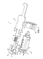
- FIGS. 1 to 12 show a preferred embodiment of a mechanical steering lock according to the present invention.
- This mechanical steering lock 1 has an actuatable by a key lock cylinder 10 with a cobblestone extension 13 and a cobblestone 11, a counter-holder 20 with a Gegenhalternase 28, a helical compression spring 3, a cam 30, a lifting rod 40 and a housing 2.
- the front side of the lock cylinder 10 is provided with an opening for an axial keyway 10b, in which the key is inserted.
- the rigid cobblestone extension 13 is formed in the front portion of the lock cylinder 10.
- the cobblestone extension 13 extends substantially in the manner of a radial ring segment and has a substantially wedge-shaped cross section.
- an end-face front cobblestone extension contact surface 14a predominantly sloping at the cobblestone extension 13, and a rear cobblestone extension contact surface 14b facing away from the end face, substantially perpendicular to the lock cylinder longitudinal axis 10a.
- the lock cylinder 10 and the cobblestone extension 13 are designed as a one-piece, rigidly connected component, which is produced in the present embodiment by injection molding of a metallic alloy. Adjacent to the cobblestone extension 13, a substantially rectangular opening is formed by the lock cylinder 10, substantially perpendicular to the lock cylinder longitudinal axis 10a, in the clockwise direction, with an end view of the lock cylinder 10.
- This opening and / or guide serves to receive and guide a cobblestone 11, which has substantially the same wedge-shaped cross-section as the cobblestone extension 13 and is formed substantially radially segment-like.
- a cobblestone 11 which has substantially the same wedge-shaped cross-section as the cobblestone extension 13 and is formed substantially radially segment-like.
- an end-face front cobblestone contact surface 12a is predominantly sloping and a front cobblestone contact surface 12b facing away from the end face is formed substantially perpendicular to the longitudinal axis of the lock cylinder 10a.
- the radial travel and thus the position of the spring-loaded head block 11 is limited to a minimum and a maximum distance to the lock cylinder longitudinal axis 10a.
- the profile of the cobblestone 11 extends the annular segment extension of the cobblestone extension 13 and thus the cobblestone interface 12a extends the adjoining cobblestone extension surface 14a and the cobblestone contact surface 12b extends the adjoining cobblestone extension surface 14b.
- the cobblestone 11 is brought immediately after key withdrawal in a position with minimum distance to the lock cylinder longitudinal axis 10a. This deactivates the locking protection and locks the steering column in a torque-proof manner. Subsequently, when the key is removed from the lock cylinder 10, the cobblestone 11 is guided to a position at a maximum distance from the lock cylinder longitudinal axis 10a.
- FIG. 1 is a perspective view of the backstop 20 can be removed.
- the counter-holder 20 is arranged in the housing 2 in a counter guide 2a substantially longitudinally displaceable and controls via the lifting rod 40, the locking of the steering lock 1. Furthermore, the counter-holder 20 is still part of the interlocking protection.
- the counter-holder 20 is made as a one-piece component made of plastic.
- the slide-shaped counter-holder 20 has on the upper side and the two sides guide surfaces which correspond to the profile of the counter guide 2a and thus provide a substantially backlash-free movement within the counter guide 2a.
- a spring receptacle 26 for receiving the helical compression spring 3 is integrally formed with the anvil 20 in a front portion.
- This spring retainer 26 extends parallelepipedally and parallel to a longitudinal axis or lifting axis of the counter-holder 20.
- the spring receiver 26 forms a spike-like projection which fixes the helical compression spring 3 radially.
- the counter-holder 20 is pressed by the helical compression spring 3 to the front.
- the counterpart 20 has a first counterholder contact surface 21, which is designed as a planar surface and extends substantially perpendicular to the lock cylinder longitudinal axis 10a.
- the front side, such as out FIG. 8 a mating nose 28 is integrally formed in the anvil 20.
- the counter-nose 28 has on the side facing the lock cylinder 10 side a chamfer 25 which includes a second counter-holder contact surface 22.
- Third and fourth mating contact surfaces 23, 24 are formed in a rear portion, extending from a side guide surface, substantially parallel to the first mating contact surface 21.
- the counter-holder 20 supporting helical compression spring 3 is supported on its opposite side, the lifting rod 40 from.
- the backlash-free formation of corresponding contact surface pairs for unlocking and locking, or for the interlocking protection allows.
- the skip of the counterstay nose 28 from the rear cobblestone extension contact surface 14b on the front cobblestone extension contact surface 14a causes the activation of the interlocking protection.
- the counter-nose 28 is integrally formed with the anvil 20 and is substantially flat with parallel top and bottom formed, such as out FIG. 1 is removable.
- a helical compression spring receptacle 45 integrally formed with the lifting rod 40, comparable to the spring receptacle 26 of the counter-holder 20. So that the lifting rod 40 presses the counter-holder 20 via the helical compression spring 3 and at a locking of the anvil 20 blocked the lifting rod 40, 40 plane-parallel surfaces or contact surfaces are formed even in the lifting rod, which extend substantially perpendicular to a Hubstangenl Kunststoffsachse 40a.
- the lifting rod 40 is movable between a blocking position for blocking a steering spindle and a release position for releasing the steering spindle in a lifting axis.
- a first Hubstangen Chemistry 41 is formed adjacent to the helical compression spring receptacle 45 in a front portion. This surface runs essentially parallel to the lifting rod longitudinal axis 40a.
- a second and a third Hubstangen Chemistry 42, 43 parallel to the first Hubstangenisation 41. These three surfaces extend on the same side of the lifting rod 40 and are substantially plane-parallel. Opposite this U-shaped recess, so on the other side of the lifting rod 40, there is another U-shaped recess in the center of which a downwardly curved or curved Hubnase 46 is formed. The side surface of Hubnase 46 in turn has a fourth Hubstangen Chemistry 44. This fourth lift rod surface 44 is aligned substantially parallel to the first to third lift rod surfaces 41, 42, 43, but has rounded edges.
- the cam wheel 30 is rotatably connected to the lock cylinder 10, in particular by means of a positive configuration.
- the cam wheel 30 an outer lifting cam 31, which is on the fourth Hubstangen Chemistry 44 Hubnase 46 with the lifting rod 40 during unlocking engaged, the travel of the lifting rod 40 preferably parallel to the lock cylinder longitudinal axis 10a extends (see. FIG. 5 ).
- the fourth Hubstangenisation 44 advantageously rounded edges.
- This lift curve 31 is formed spirally and is in its last section in a subsequent, flat end surface without slope over, which is referred to as a holding portion 32 and is used for safe activation of the interlocking protection.
- the lift cam 31 and the holding portion 32 both extend on the outer surface of the cam wheel 30 and are integrally formed therewith.
- FIG. 12 are schematically the various ratchets removed.
- the key not shown, is located in a first latching point 16.
- the first latching point 16 is also referred to as a zero position or starting position.
- the key can be introduced into the lock cylinder 10 and remove. So there is still no rotation and the angle of rotation of the lock cylinder is 0 °. If the lock cylinder is transferred by the key in other rotational positions, it is no longer possible to pull out the key. This is ensured by a locking mechanism.
- a second latching point 17 is often referred to as the first rotational position or ACC position. If the key is rotated in this position with the lock cylinder 10, then power for the first consumer, such as radio, etc., is already provided.
- the angle of rotation of the lock cylinder is substantially 60 °.
- a third rest stop 18 is often called a second rotational position.
- the steering lock is already fully unlocked and the interlocking protection active.
- the angle of rotation is substantially 120 °.
- the FIG. 12 nor a starter actuation position 18a can be removed, the angle of rotation substantially corresponds to 155 °.
- the locking mechanism that prevents the removal of the key from the lock cylinder 10 outside the first detent position engages.
- the lift cam 31 presses on the fourth Hubstangenisation 44 and thus moves over the Hubnase 46 axially the lifting rod 40.
- the first counter-contact surface 21 additionally has contact with the rear cobblestone extension contact surface 14b at a rotation angle of approximately 45 °. This constant unlocking is completed at about 85 ° rotation angle and thus before reaching the third rest stop 18. In this case, the lifting cam 31 merges into the holding section 32 of the cam wheel, which no longer has an incline (see FIG. FIG. 7 ).
- the anvil 20 moves forward in the direction of the end face of the lock cylinder 10, and briefly there is only contact between the holding portion 32 and the fourth Hubstangen Chemistry 44.
- the contact surface pair third JacobhalterMap relations 23 and second Hubstangen Chemistry 42 in turn pressed together by the spring force of the helical compression spring 3 (see. FIG. 8 ).
- the counter-nose 28 changes from the rear to the front side of the cobblestone extension 13, that is from the rear cobblestone extension contact surface 14b, to the front cobblestone extension contact surface 14a.
- the lifting rod 40 is fixed by means of the fourth Hubstangen Chemistry 44 by the holding portion 32, which in turn via the helical compression spring 3, the anvil 20 positioned.
- the forward movement or the swiveling of the counter-latching lug 28 from the side facing the rear cobblestone extension contact surface 14b is thus carried out on the side facing the front cobblestone extension contact surface 14a.
- the lock cylinder is rotated further in the direction of the starter actuation position 18a, the lift rod 40 is positively locked by means of the fourth lift rod surface 44 and by the holding section 32, thus preventing locking of the steering spindle. If the lock cylinder is rotated back in the direction of the first latching position 16, then first the contact surface pair front cobblestone extension contact surface 14a and second counterholder contact surface 22. This contact surface pair blocked again on the contact surface pair third counterholder contact surface 23 and second Hubstangen Chemistry 42, the axial movement of the lifting rod 40 and thus forms the Locking protection of the steering lock.
- the front cobblestone extension contact surface 14a is replaced by the front cobblestone contact surface 12a and forms, together with the second counter-contact surface 22, a further contact surface pair.
- This pair of contact surfaces still blocks movement of the lifting rod 40 and remains until reaching the starting position, ie the first latching point 16, and removal of the key from the lock cylinder 10 to at least 2/3 of the removal path exist, and thus forms a reliable Lock protection.
- the cobblestone 11 is moved in the direction of the lock cylinder axis 10a.
- the positive connection or the contact surface pair front cobblestone contact surface 12a and second counter-holder contact surface 22 is dissolved and thus the lifting rod 40 is freely movable again.
- the steering lock now locks the steering shaft against rotation.
- a die casting process with a zamak alloy e.g. ZnAl4Cu1 conceivable.
Landscapes
- Engineering & Computer Science (AREA)
- Mechanical Engineering (AREA)
- Lock And Its Accessories (AREA)
Abstract
Description
- Die Erfindung betrifft eine mechanische Lenkverriegelung für ein Fahrzeug mit einem von einem Schlüssel betätigbaren Schließzylinder gemäß des Oberbegriffs des Anspruch 1.
- Aus dem Stand der Technik sind mechanische Lenkverriegelungen mit einem von einem Schlüssel betätigbaren Schließzylinder und einem durch einen Kopfstein gebildeten Verriegelungsschutz bei entsperrter Lenkverriegelung bekannt. Hierbei wird der Drehwinkel eines Schließzylinders allein durch die maximale Baubreite des Kopfsteins in Relation zum Durchmesser eines den Kopfstein führenden Schließzylinders begrenzt. Ein erweiterter Verdrehwinkel des Schließzylinders scheitert an den mechanischen Vorgaben für eine sichere Führung des Kopfsteins innerhalb des Schließzylinders.
- Der Erfindung liegt daher die Aufgabe zugrunde, eine mechanische Lenkverriegelung für ein Fahrzeug zur Verfügung zu stellen, welche einen großen Drehwinkel des Schließzylinders von 85° und mehr ermöglicht, kostengünstig und durch hohe Toleranzen mechanisch stabil zu fertigen ist und einen Schutz gegen unabsichtliches Verriegeln bietet.
- Diese Aufgabe wird durch eine mechanische Lenkverriegelung für ein Fahrzeug mit den Merkmalen des Anspruchs 1 gelöst. Vorteilhafte Ausführungsformen und Weiterbildungen der Erfindung werden in den Unteransprüchen beschrieben.
- Dazu wird erfindungsgemäß eine mechanische Lenkverriegelung für ein Fahrzeug zur Verfügung gestellt, welche folgendes aufweist:
- ● einen von einem Schlüssel betätigbaren Schließzylinder mit einem Kopfstein und einer Kopfsteinverlängerung, beispielsweise aus Druckgussmaterial hergestellt,
- ● einen Gegenhalter mit einer Gegenhalternase, beispielsweise aus Druckguss- oder Spritzgussmaterial hergestellt,
- ● ein Nockenrad mit einer auf einer Außenfläche ausgebildeten Hubkurve, beispielsweise aus Druckguss- oder Spritzgussmaterial hergestellt, und
- ● eine Hubstange, die zwischen einer Sperrstellung zur Sperrung einer Lenkspindel und einer Freigabestellung zur Freigabe der Lenkspindel in einer Hubachse beweglich ist, beispielsweise aus Stahl, und/oder Druckgussmaterial hergestellt.
- Um einen Verriegelungsschutz vor Schlüsselabzug für große Drehwinkel des Schließzylinders von mehr als 85°, insbesondere bis zu 155° zur Verfügung zu stellen, ist die starre Kopfsteinverlängerung vorgesehen, die zusammen mit dem Kopfstein einen Verriegelungsschutz bildet.
- Vorteilhafterweise ist bei der mechanischen Lenkverriegelung die Kopfsteinverlängerung an den Schließzylinder angrenzend und mit diesem einstückig oder starr verbunden. Durch diese integrale Ausbildung wird ein weiteres Bauteil vermieden und gleichzeitig, durch die daraus resultierende Spielfreiheit, die Funktionssicherheit bei diesem sicherheitsrelevanten Bauteil erhöht.
- Nach einer weiteren vorteilhaften Ausführungsform überdeckt die Kopfsteinverlängerung einen Bogenwinkel von mehr als 55° und bildet zusammen mit dem Kopfstein und dem Gegenhalter einen Verriegelungsschutz von mehr als 85°, vorzugsweise 100°, besonders bevorzugt 155°
- Die Kopfsteinverlängerung weist vorteilhafterweise einen sich radial erstreckenden kegel- oder keilförmigen Querschnitt auf. Mit dieser geometrischen Ausbildung wird ein Überspringen der Gegenhalternase von der hinteren Kopfsteinverlängerungskontaktfläche auf die vordere Kopfsteinverlängerungskontaktfläche während der Entriegelung verhindert.
- Vorteilhafterweise wird der Kopfstein im Wesentlichen senkrecht zur Schließzylinderachse angeordnet. Damit wird der Kopfstein bei nicht eingestecktem Schlüssel in einer Position nahe an der Schließzylinderlängsachse aufgenommen. Hiermit ist der Verriegelungsschutz deaktiviert und die Lenksäule drehfest verriegelt.
- Die Hubstange wird vorteilhafterweise beim Entriegeln von der Hubkurve des Nockenrads im Wesentlichen parallel zur Schließzylinderachse, zwischen einer Sperrstellung zur Sperrung einer Lenkspindel und einer Freigabestellung zur Freigabe der Lenkspindel, bewegt. Dabei drückt die Hubstange den Gegenhalter durch eine zwischen der Hubstange und dem Gegenhalter angeordnete Schraubendruckfeder gegen eine hintere Kopfsteinverlängerungskontaktfläche der Kopfsteinverlängerung. Dies ermöglicht eine kompakte Bauform der mechanischen Lenkverriegelung.
- Vorteilhafterweise wird der Verriegelungsschutz durch formschlüssige Eingriffe gebildet. Hierfür wird vor dem Erreichen der dritten Raststelle eine unabsichtliche Verriegelung durch das Blockieren der Hubstange verhindert, in dem die Gegenhalternase des Gegenhalters, aufgrund der Druckspannung der Schraubendruckfeder, die von der Hubkurve des Nockenrads über die Hubstange an der Schraubendruckfeder aufgebaut wurde, vor die Kopfsteinverlängerung geschoben wird und die vordere Kopfsteinverlängerungskontaktfläche gegenüber der zweiten Kontaktfläche auf der Gegenhalternase zum Eingriff kommt.
- Die Lenkverriegelung weist vorteilhafterweise ein Gehäuse auf, wobei in dem Gehäuse im Wesentlichen angeordnet sind: der Schließzylinder mit der Kopfsteinverlängerung, der Kopfstein, der Gegenhalter, das Nockenrad, die Hubstange und die Schraubendruckfeder.
- Nachfolgend wird die Erfindung anhand eines Ausführungsbeispiels zusammen mit den beigefügten Zeichnungen erläutert. Dazu zeigt:
- F igur 1 eine perspektivische Explosionsansicht einer mechanischen Lenkverriegelung gemäß einer bevorzugten Ausführungsform der vorliegenden Erfindung;
- F igur 2 eine perspektivische Detailansicht der Einbaulage eines Gegenhalters in einem Gehäuse der mechanischen Lenkverriegelung gemäß einer bevorzugten Ausführungsform der vorliegenden Erfindung;
- F igur 3 eine perspektivische Ansicht des Gehäuses der mechanischen Lenkverriegelung gemäß einer bevorzugten Ausführungsform der vorliegenden Erfindung;
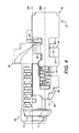
- F igur 4 eine Draufsicht auf die mechanische Lenkverriegelung in einer ersten Rastposition bei einem Drehwinkel des Schließzylinders von 0°, gemäß einer bevorzugten Ausführungsform der vorliegenden Erfindung;
- F igur 5 eine Draufsicht auf die mechanische Lenkverriegelung bei einem Drehwinkel des Schließzylinders von 45°0, gemäß einer bevorzugten Ausführungsform der vorliegenden Erfindung;
- F igur 6 eine perspektivische Ansicht der mechanischen Lenkverriegelung bei einem Drehwinkel des Schließzylinders von ca. 100°, gemäß einer bevorzugten Ausführungsform der vorliegenden Erfindung;
- F igur 7 eine Draufsicht auf ein Nockenrad und eine Hubstange wiederum bei einem Drehwinkel des Schließzylinders von ca. 100°, gemäß einer bevorzugten Ausführungsform der vorliegenden Erfindung;
- F igur 8 eine perspektivische Ansicht der mechanischen Lenkverriegelung bei einem Drehwinkel des Schließzylinders von 90°, beim Zurückdrehen von 120° oder von mehr als 100°, gemäß einer bevorzugtenAusführungsform der vorliegenden Erfindung;
- F igur 9 eine perspektivische Detailansicht des Nockenrads und der Hubstange bei einem Drehwinkel des Schließzylinders von 90°, beim Zurückdrehen von 120° oder von mehr als 100°, gemäß einer bevorzugten Ausführungsform der vorliegenden Erfindung;
- F igur 10 eine weitere perspektivische Detailansicht des Nockenrads und der Hubstange bei einem Drehwinkel des Schließzylinders von 90°, beim Zurückdrehen von 120° oder von mehr als 100°, gemäß einer bevorzugten Ausführungsform der vorliegenden Erfindung;
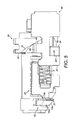
- F igur 11 eine Schnittdarstellung der mechanischen Lenkverriegelung in der ersten Rastposition bei einem Drehwinkel des Schließzylinders von 0° und noch nicht vollständig entferntem Schlüssel, gemäß einer bevorzugten Ausführungsform der vorliegenden Erfindung und
- F igur 12 eine schematische Darstellung der Raststellungen des Schließzylinders, gemäß einer bevorzugten Ausführungsform der vorliegenden Erfindung.
- Nachfolgend beziehen sich Richtungsangaben auf die Zeichnungsebene bzw. auf die Schließzylinderlängsachse sofern sich aus dem Text nichts anderes ergibt.
- Die
Figuren 1 bis 12 zeigen eine bevorzugte Ausführungsform einer mechanischen Lenkverriegelung gemäß der vorliegenden Erfindung. Diese mechanische Lenkverriegelung 1 weist einen von einem Schlüssel betätigbaren Schließzylinder 10 mit einer Kopfsteinverlängerung 13 und einem Kopfstein 11, einen Gegenhalter 20 mit einer Gegenhalternase 28, einer Schraubendruckfeder 3, einem Nockenrad 30, einer Hubstange 40 und einem Gehäuse 2 auf. Stirnseitig ist der Schließzylinder 10 mit einer Öffnung für einen axialen Schlüsselkanal 10b versehenen, in den der Schlüssel einsteckbar ist. Des Weiteren ist im vorderen Abschnitt des Schließzylinders 10, die starre Kopfsteinverlängerung 13 ausgebildet. Die Kopfsteinverlängerung 13 erstreckt sich im Wesentlichen radial ringsegmentartig und hat einen im Wesentlichen keilförmigen Querschnitt. Ferner ist an der Kopfsteinverlängerung 13 eine stirnseitige, vordere Kopfsteinverlängerungskontaktfläche 14a überwiegend schräg abfallend, und eine der Stirnseite abgewandte, hintere Kopfsteinverlängerungskontaktfläche 14b, im Wesentlichen senkrecht zur Schließzylinderlängsachse 10a, ausgebildet. Der Schließzylinder 10 und die Kopfsteinverlängerung 13 sind als einstückiges, starr verbundenes Bauteil ausgeführt, welches im vorliegenden Ausführungsbeispiel im Spritzgussverfahren aus einer metallischen Legierung hergestellt wird. Angrenzend an die Kopfsteinverlängerung 13 ist im Uhrzeigersinn, bei stirnseitiger Draufsicht auf den Schließzylinder 10, eine im Wesentlichen rechteckförmige Öffnung durch den Schließzylinder 10, im Wesentlichen senkrecht zur Schließzylinderlängsachse 10a, ausgebildet. - Diese Öffnung und/oder Führung dient zur Aufnahme und Führung eines Kopfsteines 11, der im Wesentlichen den gleichen keilförmigen Querschnitt wie die Kopfsteinverlängerung 13 aufweist und im Wesentlichen radial segmentartig ausgebildet ist. Bei dem Kopfstein 11 sind eine stirnseitige, vordere Kopfsteinkontaktfläche 12a überwiegend schräg abfallend und eine der Stirnseite abgewandte, hintere Kopfsteinkontaktfläche 12b im Wesentlichen senkrecht zur Schließzylinderlängsachse 10a ausgebildet.
- Innerhalb dieser Führung wird der radiale Verfahrweg und damit die Position des federbelasteten Kopfsteins 11 auf einen minimalen und einen maximalen Abstand zur Schließzylinderlängsachse 10a begrenzt. Befindet sich der Kopfstein 11 in der Position mit maximalem Abstand zur Schließzylinderlängsachse 10a, dann verlängert das Profil des Kopfsteins 11 die ringsegmentförmige Ausdehnung der Kopfsteinverlängerung 13, und damit verlängert die Kopfsteinkontaktfläche 12a die angrenzende Kopfsteinverlängerungskontaktfläche 14a und die Kopfsteinkontaktfläche 12b die angrenzende Kopfsteinverlängerungskontaktfläche 14b. Durch das Abfallen der vorderen Kopfsteinkontaktfläche 12a wird das Verriegeln beim Entfernen des Schlüssels aus dem Schließzylinder 10 erleichtert und gleichzeitig der Verschleiß minimiert.
- Der Kopfstein 11 wird unmittelbar nach Schlüsselabzug in eine Position mit minimalem Abstand zur Schließzylinderlängsachse 10a gebracht. Hiermit wird der Verriegelungsschutz deaktiviert und die Lenksäule drehfest verriegelt. Darauffolgend wird der Kopfstein 11 bei aus dem Schließzylinder 10 abgezogenem Schlüssel in eine Position mit maximalem Abstand zur Schließzylinderlängsachse 10a geführt.
- Aus
Figur 1 ist eine perspektivische Ansicht des Gegenhalters 20 entnehmbar. InFigur 2 ist die Einbauposition des Gegenhalters 2 in dem Gehäuse detailliert abgebildet. Der Gegenhalter 20 ist in dem Gehäuse 2 in einer Entgegenhalterführung 2a im Wesentlichen längsverschiebbar angeordnet und steuert über die Hubstange 40 die Verriegelung der Lenkverriegelung 1. Des Weiteren ist der Gegenhalter 20 noch Bestandteil des Verriegelungsschutzes. Dabei ist der Gegenhalter 20 als einstückiges Bauteil aus Kunststoff hergestellt. Der schlittenförmige Gegenhalter 20 besitzt auf der Oberseite und den beiden Seiten Führungsflächen, die dem Profil der Entgegenhalterführung 2a entsprechen und somit eine im Wesentlichen spielfreie Bewegung innerhalb der Entgegenhalterführung 2a zur Verfügung stellen. Innerhalb der Führungsflächen ist in einem vorderen Abschnitt eine Federaufnahme 26 zur Aufnahme der Schraubendruckfeder 3 einstückig mit dem Gegenhalter 20 ausgebildet. Diese Federaufnahme 26 erstreckt sich quaderförmig und parallel zu einer Längsachse bzw. Hubachse des Gegenhalters 20. Dabei bildet die Federaufnahme 26 einen dornartigen Vorsprung, der die Schraubendruckfeder 3 radial fixiert. Damit wird der Gegenhalter 20 durch die Schraubendruckfeder 3 nach vorne gedrückt. Stirnseitig weist der Entgegenhalter 20 eine erste Gegenhalterkontaktfläche 21 auf, die als plane Fläche ausgebildet ist und sich im Wesentlichen senkrecht zu der Schließzylinderlängsachse 10a erstreckt. Des Weiteren ist stirnseitig, wie z.B. ausFigur 8 entnehmbar, eine Gegenhalternase 28 integral in dem Gegenhalter 20 ausgebildet. - Die Gegenhalternase 28 weist auf der dem Schließzylinder 10 stirnseitig zugewandten Seite eine Abschrägung 25 auf, die eine zweite Gegenhalterkontaktfläche 22 umfasst. Eine dritte und vierte Gegenhalterkontaktfläche 23, 24 sind in einem hinteren Abschnitt, sich von einer seitlichen Führungsfläche erstreckend, im Wesentlichen parallel zu der ersten Gegenhalterkontaktfläche 21 ausgebildet. Mit dieser geometrischen Ausbildung wird ein Überspringen der Gegenhalternase 28 von der hinteren Kopfsteinverlängerungskontaktfläche 14b auf die vordere Kopfsteinverlängerungskontaktfläche 14a während der Entriegelung verhindert.
- Die an ihrer Vorderseite den Gegenhalter 20 abstützende Schraubendruckfeder 3 stützt an ihrer gegenüberliegen Seite die Hubstange 40 ab. Damit wird die spielfreie Bildung entsprechender Kontaktflächenpaare für die Ent- und Verriegelung, bzw. für den Verriegelungsschutz, ermöglicht. Des Weiteren wird durch die Federkraft, kurz vor Erreichen der dritten Raststelle 18, das Überspringen der Gegenhalternase 28 von der hinteren Kopfsteinverlängerungskontaktfläche 14b auf die vordere Kopfsteinverlängerungskontaktfläche 14a, zur Aktivierung des Verriegelungsschutzes, bewirkt.
- Die Gegenhalternase 28 ist einstückig mit dem Gegenhalter 20 ausgebildet und ist im Wesentlichen mit parallel verlaufender Ober- und Unterseite flach ausgebildet, wie z.B. aus
Figur 1 entnehmbar ist. Im stirnseitigen Bereich ist für die Aufnahme der Schraubendruckfeder 3 eine Schraubendruckfederaufnahme 45 integral mit der Hubstange 40 ausgebildet, vergleichbar mit der Federaufnahme 26 des Gegenhalters 20. Damit die Hubstange 40 bei einer Entriegelung den Gegenhalter 20 über die Schraubendruckfeder 3 drückt und bei einer Verriegelung der Gegenhalter 20 die Hubstange 40 blockiert, sind auch bei der Hubstange 40 planparallele Flächen bzw. Kontaktflächen ausgebildet, die sich im Wesentlichen senkrecht zu einer Hubstangenlängsachse 40a erstrecken. Dabei ist die Hubstange 40 zwischen einer Sperrstellung zur Sperrung einer Lenkspindel und einer Freigabestellung zur Freigabe der Lenkspindel in einer Hubachse beweglich. Eine erste Hubstangenfläche 41 ist angrenzend an die Schraubendruckfederaufnahme 45 in einem vorderen Abschnitt ausgebildet. Diese Fläche verläuft im Wesentlichen parallel zur Hubstangenlängsachse 40a. - In einer ersten U-förmigen Ausnehmung erstrecken sich in der Hubstange 40 eine zweite und eine dritte Hubstangenfläche 42, 43 parallel zur ersten Hubstangenfläche 41. Diese drei Flächen erstrecken sich auf der gleichen Seite der Hubstange 40 und sind im Wesentlichen planparallel. Gegenüber dieser U-förmigen Ausnehmung, also auf der anderen Seite der Hubstange 40, befindet sich eine weitere U-förmige Ausnehmung, in deren Zentrum eine nach unten gebogene bzw. gewölbte Hubnase 46 ausgebildet ist. Die Seitenfläche der Hubnase 46 weist wiederum eine vierte Hubstangenfläche 44 auf. Diese vierte Hubstangenfläche 44 ist im Wesentlichen parallel zu der ersten bis dritten Hubstangenfläche 41, 42, 43 ausgerichtet, weist jedoch abgerundete Kanten auf.
- Zur Ansteuerung der Hubstange 40 ist das Nockenrad 30 mit dem Schließzylinder 10 drehfest verbunden, insbesondere mittels einer formschlüssigen Ausgestaltung. Zur Umsetzung der Drehbewegung des Nockenrads 30 in eine translatorische Bewegung der Hubstange 40 weist das Nockenrad 30 eine außen liegende Hubkurve 31 auf, die über die vierte Hubstangenfläche 44 der Hubnase 46 mit der Hubstange 40 beim Entriegeln im Eingriff steht, wobei der Verfahrweg der Hubstange 40 vorzugsweise parallel zur Schließzylinderlängsachse 10a verläuft (vergl.
Figur 5 ). Um den Verschleiß und Reibgeräusche zwischen der Hubkurve des Nockenrads 30 und der Hubkurve 31 zu verringern, weist die vierte Hubstangenfläche 44 vorteilhafterweise abgerundete Kanten auf. Diese Hubkurve 31 ist spiralförmig ausgebildet und geht in ihrem letzten Abschnitt in eine anschließende, ebene Endfläche ohne Steigung über, die als Halteabschnitt 32 bezeichnet wird und zur sicheren Aktivierung des Verriegelungsschutzes dient. Die Hubkurve 31 und der Halteabschnitt 32 erstrecken sich beide an der Außenfläche des Nockenrads 30 und sind integral mit diesem ausgebildet. - Aus
Figur 12 sind schematisch die verschiedenen Rastellen entnehmbar. Schematisch befindet sich der nicht dargestellte Schlüssel in einer ersten Raststelle 16. Dabei wird die erste Raststelle 16 auch als Null-Lage bzw. Ausgangsposition bezeichnet. Hierbei lässt sich der Schlüssel in den Schließzylinder 10 einbringen und entfernen. Es liegt also noch keine Drehung vor und der Drehwinkel des Schließzylinders beträgt 0°. Wird der Schließzylinder von dem Schlüssel in andere Drehstellungen überführt, so ist ein Herausziehen des Schlüssels nicht mehr möglich. Dafür sorgt eine Verriegelungsmechanik. Eine zweite Raststelle 17 wird oft auch als erste Drehlage oder ACC Stellung bezeichnet. Wird der Schlüssel in diese Position mit dem Schließzylinder 10 gedreht, dann wird bereits Strom für die ersten Verbraucher, wie Radio etc., zur Verfügung gestellt. Hierbei beträgt der Drehwinkel des Schließzylinders im Wesentlichen 60°. Schließlich wird eine dritte Raststelle 18 oft auch als zweite Drehlage benannt. Hierbei ist die Lenkverriegelung bereits vollständig entriegelt und der Verriegelungsschutz aktiv. Dabei weist der Drehwinkel im Wesentlichen 120° auf. Des Weiteren ist derFigur 12 noch eine Anlasserbetätigungsposition 18a entnehmbar, deren Drehwinkel im Wesentlichen 155° entspricht. - Nach der Einbringung des Schlüssels in den Schlüsselkanal 10b des Schließzylinders 10 in der ersten Raststelle 16 ist das Kontaktflächenpaar dritte Gegenhalterkontaktfläche 23 und zweite Hubstangenfläche 42 durch die Federkraft der Schraubendruckfeder 3 aneinandergedrückt, die zwischen der Federaufnahme 26 des Gegenhalters 20 und der Schraubendruckfederaufnahme 45 der Hubstange wirkt. Mit Beginn der Drehung des Schlüssels und damit des Schließzylinders 10 beginnt kontinuierlich die Entriegelung der Lenkverriegelung 1.
- Gleichzeitig greift die Verriegelungsmechanik, die das Entnehmen des Schlüssels aus dem Schließzylinder 10 außerhalb der ersten Raststellung verhindert. Bei der Entriegelung wird das Kontaktflächenpaar dritte Gegenhalterkontaktfläche 23 und zweite Hubstangenfläche 42 weiterhin durch die Federkraft der Schraubendruckfeder 3 aneinandergedrückt. Zusätzlich drückt die Hubkurve 31 auf die vierte Hubstangenfläche 44 und bewegt damit über die Hubnase 46 axial die Hubstange 40. Wie aus
Figur 5 ersichtlich, hat die erste Gegenhalterkontaktfläche 21 zusätzlich Kontakt mit der hinteren Kopfsteinverlängerungskontaktfläche 14b bei einem Drehwinkel von ca. 45°. Diese konstante Entriegelung ist bei ca. 85° Drehwinkel und damit vor Erreichen der dritten Raststelle 18 abgeschlossen. Hierbei geht die Hubkurve 31 in den Halteabschnitt 32 des Nockenrads über, der keine Steigung mehr aufweist (vergl.Figur 7 ). - Bei weiterer Drehung des Schließzylinders 10 bewegt sich der Gegenhalter 20 nach vorne in Richtung Stirnseite des Schließzylinders 10, und kurzzeitig gibt es nur noch Kontakt zwischen dem Halteabschnitt 32 und der vierten Hubstangenfläche 44. Nach Beendigung der Vorwärtsbewegung des Gegenhalters 20 besteht wieder zusätzlich das Kontaktflächenpaar dritte Gegenhalterkontaktfläche 23 und zweite Hubstangenfläche 42, wiederum durch die Federkraft der Schraubendruckfeder 3 aneinandergedrückt (vergl.
Figur 8 ). Während der Vorwärtsbewegung des Gegenhalters 20, wechselt die Gegenhalternase 28 von der hinteren auf die vordere Seite der Kopfsteinverlängerung 13, also von der hinteren Kopfsteinverlängerungskontaktfläche 14b auf die vordere Kopfsteinverlängerungskontaktfläche 14a. Um diesen Wechsel der Gegenhalternase 20 sicherzustellen, wird die Hubstange 40 mittels der vierten Hubstangenfläche 44 durch den Halteabschnitt 32 fixiert, die wiederum über die Schraubendruckfeder 3 den Gegenhalter 20 positioniert. Bis zum Erreichen der dritten Raststelle 18 ist somit die Vorwärtsbewegung bzw. das Umschwenken der Gegenhalternase 28 von der der hinteren Kopfsteinverlängerungskontaktfläche 14b zugewandten Seite auf die der vorderen Kopfsteinverlängerungskontaktfläche 14a zugewandten Seite durchgeführt. - Wird der Schließzylinder weiter Richtung Anlasserbetätigungsposition 18a gedreht, wird die Hubstange 40 mittels der vierten Hubstangenfläche 44 und durch den Halteabschnitt 32 formschlüssig blockiert und damit ein Verriegeln der Lenkspindel verhindert. Wird der Schließzylinder wieder zurück in Richtung erste Rastposition 16 gedreht, dann bildet sich zunächst das Kontaktflächenpaar vordere Kopfsteinverlängerungskontaktfläche 14a und zweite Gegenhalterkontaktfläche 22. Dieses Kontaktflächenpaar blockiert wiederum über das Kontaktflächenpaar dritte Gegenhalterkontaktfläche 23 und zweite Hubstangenfläche 42 die axiale Bewegung der Hubstange 40 und bildet somit den Verriegelungsschutz der Lenkverriegelung. Mit weiterer Drehbewegung des Schließzylinders in Richtung Ausgangsposition wird die vordere Kopfsteinverlängerungskontaktfläche 14a durch die vordere Kopfsteinkontaktfläche 12a ersetzt und bildet zusammen mit der zweiten Gegenhalterkontaktfläche 22 ein weiteres Kontaktflächenpaar. Dieses Kontaktflächenpaar blockiert weiterhin eine Bewegung der Hubstange 40 und bleibt bis zum Erreichen der Ausgangsposition, also der Ersten Raststelle 16, und Entnahme des Schlüssels aus dem Schließzylinder 10 zu mindestens 2/3 des Entnahmeweges, bestehen, und bildet somit einen zuverlässigen Verriegelungsschutz. Nach Entnahme des Schlüssels aus dem Schließzylinder 10 wird der Kopfstein 11 Richtung Schließzylinderachse 10a bewegt. Damit wird die formschlüssige Verbindung bzw. das Kontaktflächenpaar vordere Kopfsteinkontaktfläche 12a und zweite Gegenhalterkontaktfläche 22 aufgelöst und damit ist die Hubstange 40 wieder frei bewegbar. Die Lenkverriegelung sperrt jetzt die Lenkspindel gegen Verdrehung.
- Durch die Entkopplung von Ent- und Verriegeln bzw. Ver- und Entriegeln wird hierbei ein größtmöglicher Drehwinkel des Schließzylinders zur Verfügung gestellt, bei gleichzeitig geringem Platzbedarf und hoher Funktionssicherheit.
- In einer nicht gezeigten abgewandelten Ausführungsform sind für den Kopfstein und/oder dessen Querschnitt auch andere geometrische Formen denkbar. Des Weiteren ist auch eine schwenk- bzw. klappbare Lagerung an bzw. in einem Schließzylinder denkbar.
- In weiteren Ausführungsformen ist für ein Zylinderschloss mit drei Raststellungen auch denkbar, dass ein Schlüssel bzw. ein Betätiger des Zylinderschlosses ausgehend mit einer Drehung von einer dritten Raststellung beim Erreichen einer zweiten Raststellung abziehbar bzw. dem Zylinderschloss entnehmbar ist und dennoch die Lenkverriegelung sperrend in die Lenksäule eingreift.
- In weiteren Ausführungsformen sind für ein Zylinderschloss mit Haltenase auch andere Herstellungsverfahren wie Spritzguss, Sinterverfahren, als auch andere Werkstoffe wie Verbundwerkstoffe, Kunststoffe, metallische Verbindung etc. denkbar.
- Ebenfalls sind für die Herstellung einer Hubstange auch andere Verfahren wie Spritzguss, Sinterverfahren, Stanzen, als auch andere Werkstoffe wie Verbundwerkstoffe, Kunststoffe, metallische Verbindung etc. denkbar.
- In einer weiteren Ausführungsform ist für die Herstellung des Gegenhalters 20 ein Druckgussverfahren mit einer Zamak-Legierung, z.B. ZnAl4Cu1 denkbar.
-
- 1
- Lenkverriegelung bzw. Lenkschloss
- 2
- Gehäuse
- 2a
- Entgegenhalterführung
- 3
- Schraubendruckfeder
- 9
- Zylindergehäuse
- 10
- Schließzylinder
- 10a
- Schließzylinderlängsachse
- 10b
- Schlüsselkanal
- 11
- Kopfstein
- 12a
- vordere Kopfsteinkontaktfläche
- 12b
- hintere Kopfsteinkontaktfläche
- 13
- Kopfsteinverlängerung
- 14a
- vordere Kopfsteinverlängerungskontaktfläche
- 14b
- hintere Kopfsteinverlängerungskontaktfläche
- 15
- Schließzylindergehäuse
- 16
- erste Raststelle
- 17
- zweite Raststelle
- 18
- dritte Raststelle
- 18a
- Anlasserbetätigungsposition
- 20
- Gegenhalter
- 21
- erste Gegenhalterkontaktfläche
- 22
- zweite Gegenhalterkontaktfläche
- 23
- dritte Gegenhalterkontaktfläche
- 24
- vierte Gegenhalterkontaktfläche
- 25
- Abschrägung
- 26
- Federaufnahme
- 28
- Gegenhalternase
- 30
- Nockenrad
- 31
- Hubkurve
- 32
- Halteabschnitt
- 40
- Hubstange
- 40a
- Hubstangenlängsachse
- 41
- erste Hubstangenfläche
- 42
- zweite Hubstangenfläche
- 43
- dritte Hubstangenfläche
- 44
- vierte Hubstangenfläche
- 45
- Schraubendruckfederaufnahme
- 46
- Hubnase
Claims (8)
- Lenkverriegelung (1) für ein Fahrzeug, welche folgendes aufweist:einen von einem Schlüssel betätigbaren Schließzylinder (10) mit einem Kopfstein (11),einen Gegenhalter (20) mit einer Gegenhalternase (28),ein Nockenrad (30) mit einer auf einer Außenfläche ausgebildeten Hubkurve (31) undeine Hubstange (40), die zwischen einer Sperrstellung zur Sperrung einer Lenkspindel und einer Freigabestellung zur Freigabe der Lenkspindel in einer Hubachse beweglich ist, dadurch gekennzeichnet, dassfür große Drehwinkel des Schließzylinders (10) von mehr als 85°, insbesondere bis zu 155°, eine starre Kopfsteinverlängerung (13) vorgesehen ist, die zusammen mit dem Kopfstein (11) einen Verriegelungsschutz vor Schlüsselabzug bildet.
- Lenkverriegelung (1) nach Anspruch 1, wobei die Kopfsteinverlängerung (13) mit dem Schließzylinder (10) einstückig oder starr verbunden ist.
- Lenkverriegelung (1) nach einem der vorhergehenden Ansprüche, wobei die Kopfsteinverlängerung (13) einen Bogenwinkel von mehr als 55° überdeckt.
- Lenkverriegelung (1) nach einem der vorhergehenden Ansprüche, wobei die Kopfsteinverlängerung (13) einen sich radial erstreckenden, kegel- oder keilförmigen Querschnitt aufweist.
- Lenkverriegelung (1) nach einem der vorhergehenden Ansprüche, wobei die Kopfsteinverlängerung (13) im Wesentlichen senkrecht zur Schließzylinderachse (10a) angeordnet ist.
- Lenkverriegelung (1) nach einem der vorhergehenden Ansprüche, wobei die Hubstange (40) beim Entriegeln von dem Nockenrad (30) mit der Hubkurve (31) im Wesentlichen parallel zur Schließzylinderachse (10a) bewegt wird und den Gegenhalter (20) durch eine zwischen der Hubstange (40) und dem Gegenhalter (20) angeordnete Schraubendruckfeder (3) gegen eine hintere Kopfsteinverlängerungskontaktfläche (14b) drückt.
- Lenkverriegelung (1) nach einem der vorhergehenden Ansprüche, wobei vor dem Erreichen einer dritten Raststelle (18) des Schlüssels eine unabsichtliche Verriegelung durch das Blockieren der Hubstange (40) verhindert wird, in dem die Gegenhalternase (28) des Gegenhalters (20) aufgrund der Druckspannung einer Schraubendruckfeder (3), die von der Hubkurve (31) des Nockenrads (30) über die Hubstange (40) an der Schraubendruckfeder (3) aufgebaut wurde, vor die Kopfsteinverlängerung (13) geschoben wird und beim Verriegeln eine vordere Kopfsteinverlängerungskontaktfläche (14a) gegenüber einer zweiten Kontaktfläche (22) auf der Gegenhalternase (28) zum Liegen kommt.
- Lenkverriegelung (1) nach einem der vorhergehenden Ansprüche, welche ferner folgendes aufweist:ein Gehäuse (2), in dem im Wesentlichen der Schließzylinder (10) mit der Kopfsteinverlängerung (13), der Kopfstein (11), der Gegenhalter (20), das Nockenrad (30), die Hubstange (40) und die Schraubendruckfeder (3) angeordnet sind.
Applications Claiming Priority (1)
| Application Number | Priority Date | Filing Date | Title |
|---|---|---|---|
| DE201110121430 DE102011121430A1 (de) | 2011-12-16 | 2011-12-16 | Mechanische Lenkverriegelung |
Publications (2)
| Publication Number | Publication Date |
|---|---|
| EP2604480A1 true EP2604480A1 (de) | 2013-06-19 |
| EP2604480B1 EP2604480B1 (de) | 2014-03-26 |
Family
ID=47080125
Family Applications (1)
| Application Number | Title | Priority Date | Filing Date |
|---|---|---|---|
| EP20120006733 Active EP2604480B1 (de) | 2011-12-16 | 2012-09-26 | Mechanische Lenkverriegelung |
Country Status (2)
| Country | Link |
|---|---|
| EP (1) | EP2604480B1 (de) |
| DE (1) | DE102011121430A1 (de) |
Citations (2)
| Publication number | Priority date | Publication date | Assignee | Title |
|---|---|---|---|---|
| DE1780228A1 (de) * | 1968-08-17 | 1972-07-06 | Voss Kg J | Lenkspindelverschluss |
| US6354117B1 (en) * | 1999-01-15 | 2002-03-12 | Valeo Securite Habitacle | Steering column anti-theft device for motor vehicle |
-
2011
- 2011-12-16 DE DE201110121430 patent/DE102011121430A1/de not_active Withdrawn
-
2012
- 2012-09-26 EP EP20120006733 patent/EP2604480B1/de active Active
Patent Citations (2)
| Publication number | Priority date | Publication date | Assignee | Title |
|---|---|---|---|---|
| DE1780228A1 (de) * | 1968-08-17 | 1972-07-06 | Voss Kg J | Lenkspindelverschluss |
| US6354117B1 (en) * | 1999-01-15 | 2002-03-12 | Valeo Securite Habitacle | Steering column anti-theft device for motor vehicle |
Also Published As
| Publication number | Publication date |
|---|---|
| EP2604480B1 (de) | 2014-03-26 |
| DE102011121430A1 (de) | 2013-06-20 |
Similar Documents
| Publication | Publication Date | Title |
|---|---|---|
| EP3482024B1 (de) | Griffvorrichtung mit einem flächenbündigen griff | |
| DE102007047595B4 (de) | Lenkradschlosseinheit | |
| EP1363815B1 (de) | Schloss, insbesondere zum verriegeln der lenkspindel eines kraftfahrzeugs | |
| EP3218246B1 (de) | Lenksäule mit längsanschlag mit einstellbarer freigabefunktion für crash | |
| EP2923418B1 (de) | Verriegelungsmechanismus für steckverbinder | |
| EP2261445B1 (de) | Schloss, insbesondere Türschloss, mit verbesserter Schließmechanik | |
| DE2060073B2 (de) | Diebstahlsicherung fuer kraftfahrzeuge | |
| EP3517714A1 (de) | Zuhaltung und sicherheitseinrichtung mit geringen abmessungen | |
| EP2679453B1 (de) | Mechanische Lenkverriegelung | |
| EP1913659B1 (de) | Elektrischer steckverbinder | |
| EP2572946B1 (de) | Verriegelungsschutz für eine elektrische Lenkverriegelung | |
| EP3144188B1 (de) | Vorrichtung zur verlagerung eines sperrelementes | |
| EP4098527B1 (de) | Rahmenschloss | |
| DE102008018623A1 (de) | Antriebselement für einen Beschlag | |
| EP2604480B1 (de) | Mechanische Lenkverriegelung | |
| DE19544840A1 (de) | Zylinderschloß mit Zylinderkern und Zuhaltungen | |
| EP4062016B1 (de) | Kraftfahrzeug-schloss | |
| EP2090727B1 (de) | Kraftfahrzeugtürschloss | |
| DE202019105467U1 (de) | Gebäudeöffnung mit einer Einrichtung zum Öffnen und Schließen sowie Ver- und Entriegel von Gebäudeöffnungen | |
| EP2806445A1 (de) | Betätigungsvorsatz zur Betätigung eines Tasters und/oder Schalters | |
| DE1555886C3 (de) | Diebstahlsicherung für Kraftfahrzeuge | |
| DE102013018836A1 (de) | Mechanische Sperrvorrichtung, insbesondere für den Fahrzeugbereich | |
| EP3453579B1 (de) | Verriegelungsvorrichtung | |
| DE102005037648B4 (de) | Baueinheit für die Verriegelung der Lenksäule an Kraftfahrzeugen | |
| EP1231102B1 (de) | Verriegelungsvorrichtung mit Doppelkopf zum gegenseitigen Verriegeln von einzeln klappbaren Rückenlehnen |
Legal Events
| Date | Code | Title | Description |
|---|---|---|---|
| PUAI | Public reference made under article 153(3) epc to a published international application that has entered the european phase |
Free format text: ORIGINAL CODE: 0009012 |
|
| AK | Designated contracting states |
Kind code of ref document: A1 Designated state(s): AL AT BE BG CH CY CZ DE DK EE ES FI FR GB GR HR HU IE IS IT LI LT LU LV MC MK MT NL NO PL PT RO RS SE SI SK SM TR |
|
| AX | Request for extension of the european patent |
Extension state: BA ME |
|
| 17P | Request for examination filed |
Effective date: 20130719 |
|
| RBV | Designated contracting states (corrected) |
Designated state(s): AL AT BE BG CH CY CZ DE DK EE ES FI FR GB GR HR HU IE IS IT LI LT LU LV MC MK MT NL NO PL PT RO RS SE SI SK SM TR |
|
| GRAP | Despatch of communication of intention to grant a patent |
Free format text: ORIGINAL CODE: EPIDOSNIGR1 |
|
| INTG | Intention to grant announced |
Effective date: 20131010 |
|
| GRAS | Grant fee paid |
Free format text: ORIGINAL CODE: EPIDOSNIGR3 |
|
| GRAA | (expected) grant |
Free format text: ORIGINAL CODE: 0009210 |
|
| AK | Designated contracting states |
Kind code of ref document: B1 Designated state(s): AL AT BE BG CH CY CZ DE DK EE ES FI FR GB GR HR HU IE IS IT LI LT LU LV MC MK MT NL NO PL PT RO RS SE SI SK SM TR |
|
| REG | Reference to a national code |
Ref country code: GB Ref legal event code: FG4D Free format text: NOT ENGLISH |
|
| REG | Reference to a national code |
Ref country code: CH Ref legal event code: EP |
|
| REG | Reference to a national code |
Ref country code: AT Ref legal event code: REF Ref document number: 658801 Country of ref document: AT Kind code of ref document: T Effective date: 20140415 |
|
| REG | Reference to a national code |
Ref country code: IE Ref legal event code: FG4D Free format text: LANGUAGE OF EP DOCUMENT: GERMAN |
|
| REG | Reference to a national code |
Ref country code: DE Ref legal event code: R096 Ref document number: 502012000500 Country of ref document: DE Effective date: 20140508 |
|
| PG25 | Lapsed in a contracting state [announced via postgrant information from national office to epo] |
Ref country code: LT Free format text: LAPSE BECAUSE OF FAILURE TO SUBMIT A TRANSLATION OF THE DESCRIPTION OR TO PAY THE FEE WITHIN THE PRESCRIBED TIME-LIMIT Effective date: 20140326 Ref country code: NO Free format text: LAPSE BECAUSE OF FAILURE TO SUBMIT A TRANSLATION OF THE DESCRIPTION OR TO PAY THE FEE WITHIN THE PRESCRIBED TIME-LIMIT Effective date: 20140626 |
|
| REG | Reference to a national code |
Ref country code: NL Ref legal event code: VDEP Effective date: 20140326 |
|
| REG | Reference to a national code |
Ref country code: LT Ref legal event code: MG4D |
|
| PG25 | Lapsed in a contracting state [announced via postgrant information from national office to epo] |
Ref country code: FI Free format text: LAPSE BECAUSE OF FAILURE TO SUBMIT A TRANSLATION OF THE DESCRIPTION OR TO PAY THE FEE WITHIN THE PRESCRIBED TIME-LIMIT Effective date: 20140326 Ref country code: SE Free format text: LAPSE BECAUSE OF FAILURE TO SUBMIT A TRANSLATION OF THE DESCRIPTION OR TO PAY THE FEE WITHIN THE PRESCRIBED TIME-LIMIT Effective date: 20140326 |
|
| PG25 | Lapsed in a contracting state [announced via postgrant information from national office to epo] |
Ref country code: RS Free format text: LAPSE BECAUSE OF FAILURE TO SUBMIT A TRANSLATION OF THE DESCRIPTION OR TO PAY THE FEE WITHIN THE PRESCRIBED TIME-LIMIT Effective date: 20140326 Ref country code: HR Free format text: LAPSE BECAUSE OF FAILURE TO SUBMIT A TRANSLATION OF THE DESCRIPTION OR TO PAY THE FEE WITHIN THE PRESCRIBED TIME-LIMIT Effective date: 20140326 Ref country code: LV Free format text: LAPSE BECAUSE OF FAILURE TO SUBMIT A TRANSLATION OF THE DESCRIPTION OR TO PAY THE FEE WITHIN THE PRESCRIBED TIME-LIMIT Effective date: 20140326 |
|
| PG25 | Lapsed in a contracting state [announced via postgrant information from national office to epo] |
Ref country code: IS Free format text: LAPSE BECAUSE OF FAILURE TO SUBMIT A TRANSLATION OF THE DESCRIPTION OR TO PAY THE FEE WITHIN THE PRESCRIBED TIME-LIMIT Effective date: 20140726 Ref country code: NL Free format text: LAPSE BECAUSE OF FAILURE TO SUBMIT A TRANSLATION OF THE DESCRIPTION OR TO PAY THE FEE WITHIN THE PRESCRIBED TIME-LIMIT Effective date: 20140326 Ref country code: CY Free format text: LAPSE BECAUSE OF FAILURE TO SUBMIT A TRANSLATION OF THE DESCRIPTION OR TO PAY THE FEE WITHIN THE PRESCRIBED TIME-LIMIT Effective date: 20140326 Ref country code: EE Free format text: LAPSE BECAUSE OF FAILURE TO SUBMIT A TRANSLATION OF THE DESCRIPTION OR TO PAY THE FEE WITHIN THE PRESCRIBED TIME-LIMIT Effective date: 20140326 Ref country code: CZ Free format text: LAPSE BECAUSE OF FAILURE TO SUBMIT A TRANSLATION OF THE DESCRIPTION OR TO PAY THE FEE WITHIN THE PRESCRIBED TIME-LIMIT Effective date: 20140326 Ref country code: RO Free format text: LAPSE BECAUSE OF FAILURE TO SUBMIT A TRANSLATION OF THE DESCRIPTION OR TO PAY THE FEE WITHIN THE PRESCRIBED TIME-LIMIT Effective date: 20140326 Ref country code: BG Free format text: LAPSE BECAUSE OF FAILURE TO SUBMIT A TRANSLATION OF THE DESCRIPTION OR TO PAY THE FEE WITHIN THE PRESCRIBED TIME-LIMIT Effective date: 20140626 |
|
| PG25 | Lapsed in a contracting state [announced via postgrant information from national office to epo] |
Ref country code: PL Free format text: LAPSE BECAUSE OF FAILURE TO SUBMIT A TRANSLATION OF THE DESCRIPTION OR TO PAY THE FEE WITHIN THE PRESCRIBED TIME-LIMIT Effective date: 20140326 Ref country code: SK Free format text: LAPSE BECAUSE OF FAILURE TO SUBMIT A TRANSLATION OF THE DESCRIPTION OR TO PAY THE FEE WITHIN THE PRESCRIBED TIME-LIMIT Effective date: 20140326 Ref country code: ES Free format text: LAPSE BECAUSE OF FAILURE TO SUBMIT A TRANSLATION OF THE DESCRIPTION OR TO PAY THE FEE WITHIN THE PRESCRIBED TIME-LIMIT Effective date: 20140326 |
|
| PG25 | Lapsed in a contracting state [announced via postgrant information from national office to epo] |
Ref country code: PT Free format text: LAPSE BECAUSE OF FAILURE TO SUBMIT A TRANSLATION OF THE DESCRIPTION OR TO PAY THE FEE WITHIN THE PRESCRIBED TIME-LIMIT Effective date: 20140728 |
|
| REG | Reference to a national code |
Ref country code: DE Ref legal event code: R097 Ref document number: 502012000500 Country of ref document: DE |
|
| PG25 | Lapsed in a contracting state [announced via postgrant information from national office to epo] |
Ref country code: DK Free format text: LAPSE BECAUSE OF FAILURE TO SUBMIT A TRANSLATION OF THE DESCRIPTION OR TO PAY THE FEE WITHIN THE PRESCRIBED TIME-LIMIT Effective date: 20140326 |
|
| PLBE | No opposition filed within time limit |
Free format text: ORIGINAL CODE: 0009261 |
|
| STAA | Information on the status of an ep patent application or granted ep patent |
Free format text: STATUS: NO OPPOSITION FILED WITHIN TIME LIMIT |
|
| 26N | No opposition filed |
Effective date: 20150106 |
|
| PG25 | Lapsed in a contracting state [announced via postgrant information from national office to epo] |
Ref country code: IT Free format text: LAPSE BECAUSE OF FAILURE TO SUBMIT A TRANSLATION OF THE DESCRIPTION OR TO PAY THE FEE WITHIN THE PRESCRIBED TIME-LIMIT Effective date: 20140326 |
|
| REG | Reference to a national code |
Ref country code: DE Ref legal event code: R097 Ref document number: 502012000500 Country of ref document: DE Effective date: 20150106 |
|
| PG25 | Lapsed in a contracting state [announced via postgrant information from national office to epo] |
Ref country code: LU Free format text: LAPSE BECAUSE OF FAILURE TO SUBMIT A TRANSLATION OF THE DESCRIPTION OR TO PAY THE FEE WITHIN THE PRESCRIBED TIME-LIMIT Effective date: 20140926 Ref country code: MC Free format text: LAPSE BECAUSE OF FAILURE TO SUBMIT A TRANSLATION OF THE DESCRIPTION OR TO PAY THE FEE WITHIN THE PRESCRIBED TIME-LIMIT Effective date: 20140326 |
|
| REG | Reference to a national code |
Ref country code: IE Ref legal event code: MM4A |
|
| PG25 | Lapsed in a contracting state [announced via postgrant information from national office to epo] |
Ref country code: BE Free format text: LAPSE BECAUSE OF NON-PAYMENT OF DUE FEES Effective date: 20140930 |
|
| PG25 | Lapsed in a contracting state [announced via postgrant information from national office to epo] |
Ref country code: SI Free format text: LAPSE BECAUSE OF FAILURE TO SUBMIT A TRANSLATION OF THE DESCRIPTION OR TO PAY THE FEE WITHIN THE PRESCRIBED TIME-LIMIT Effective date: 20140326 |
|
| PG25 | Lapsed in a contracting state [announced via postgrant information from national office to epo] |
Ref country code: IE Free format text: LAPSE BECAUSE OF NON-PAYMENT OF DUE FEES Effective date: 20140926 |
|
| REG | Reference to a national code |
Ref country code: FR Ref legal event code: PLFP Year of fee payment: 4 |
|
| REG | Reference to a national code |
Ref country code: CH Ref legal event code: PL |
|
| PG25 | Lapsed in a contracting state [announced via postgrant information from national office to epo] |
Ref country code: SM Free format text: LAPSE BECAUSE OF FAILURE TO SUBMIT A TRANSLATION OF THE DESCRIPTION OR TO PAY THE FEE WITHIN THE PRESCRIBED TIME-LIMIT Effective date: 20140326 |
|
| PG25 | Lapsed in a contracting state [announced via postgrant information from national office to epo] |
Ref country code: MT Free format text: LAPSE BECAUSE OF FAILURE TO SUBMIT A TRANSLATION OF THE DESCRIPTION OR TO PAY THE FEE WITHIN THE PRESCRIBED TIME-LIMIT Effective date: 20140326 Ref country code: GR Free format text: LAPSE BECAUSE OF FAILURE TO SUBMIT A TRANSLATION OF THE DESCRIPTION OR TO PAY THE FEE WITHIN THE PRESCRIBED TIME-LIMIT Effective date: 20140627 |
|
| PG25 | Lapsed in a contracting state [announced via postgrant information from national office to epo] |
Ref country code: HU Free format text: LAPSE BECAUSE OF FAILURE TO SUBMIT A TRANSLATION OF THE DESCRIPTION OR TO PAY THE FEE WITHIN THE PRESCRIBED TIME-LIMIT; INVALID AB INITIO Effective date: 20120926 Ref country code: LI Free format text: LAPSE BECAUSE OF NON-PAYMENT OF DUE FEES Effective date: 20150930 Ref country code: CH Free format text: LAPSE BECAUSE OF NON-PAYMENT OF DUE FEES Effective date: 20150930 Ref country code: TR Free format text: LAPSE BECAUSE OF FAILURE TO SUBMIT A TRANSLATION OF THE DESCRIPTION OR TO PAY THE FEE WITHIN THE PRESCRIBED TIME-LIMIT Effective date: 20140326 |
|
| REG | Reference to a national code |
Ref country code: FR Ref legal event code: PLFP Year of fee payment: 5 |
|
| GBPC | Gb: european patent ceased through non-payment of renewal fee |
Effective date: 20160926 |
|
| PG25 | Lapsed in a contracting state [announced via postgrant information from national office to epo] |
Ref country code: GB Free format text: LAPSE BECAUSE OF NON-PAYMENT OF DUE FEES Effective date: 20160926 |
|
| REG | Reference to a national code |
Ref country code: FR Ref legal event code: PLFP Year of fee payment: 6 |
|
| PG25 | Lapsed in a contracting state [announced via postgrant information from national office to epo] |
Ref country code: MK Free format text: LAPSE BECAUSE OF FAILURE TO SUBMIT A TRANSLATION OF THE DESCRIPTION OR TO PAY THE FEE WITHIN THE PRESCRIBED TIME-LIMIT Effective date: 20140326 |
|
| REG | Reference to a national code |
Ref country code: FR Ref legal event code: PLFP Year of fee payment: 7 |
|
| PG25 | Lapsed in a contracting state [announced via postgrant information from national office to epo] |
Ref country code: AL Free format text: LAPSE BECAUSE OF FAILURE TO SUBMIT A TRANSLATION OF THE DESCRIPTION OR TO PAY THE FEE WITHIN THE PRESCRIBED TIME-LIMIT Effective date: 20140326 |
|
| REG | Reference to a national code |
Ref country code: AT Ref legal event code: MM01 Ref document number: 658801 Country of ref document: AT Kind code of ref document: T Effective date: 20170926 |
|
| PG25 | Lapsed in a contracting state [announced via postgrant information from national office to epo] |
Ref country code: AT Free format text: LAPSE BECAUSE OF NON-PAYMENT OF DUE FEES Effective date: 20170926 |
|
| P01 | Opt-out of the competence of the unified patent court (upc) registered |
Effective date: 20230505 |
|
| PGFP | Annual fee paid to national office [announced via postgrant information from national office to epo] |
Ref country code: DE Payment date: 20250919 Year of fee payment: 14 |
|
| PGFP | Annual fee paid to national office [announced via postgrant information from national office to epo] |
Ref country code: FR Payment date: 20250922 Year of fee payment: 14 |
|
| REG | Reference to a national code |
Ref country code: DE Ref legal event code: R082 Ref document number: 502012000500 Country of ref document: DE |