EP2601467B1 - Dispositif de traitement thermique d'une bande de matière textile - Google Patents
Dispositif de traitement thermique d'une bande de matière textile Download PDFInfo
- Publication number
- EP2601467B1 EP2601467B1 EP11733846.7A EP11733846A EP2601467B1 EP 2601467 B1 EP2601467 B1 EP 2601467B1 EP 11733846 A EP11733846 A EP 11733846A EP 2601467 B1 EP2601467 B1 EP 2601467B1
- Authority
- EP
- European Patent Office
- Prior art keywords
- housing
- channels
- web
- channel
- fresh air
- Prior art date
- Legal status (The legal status is an assumption and is not a legal conclusion. Google has not performed a legal analysis and makes no representation as to the accuracy of the status listed.)
- Active
Links
- 238000010438 heat treatment Methods 0.000 title claims description 9
- 239000004753 textile Substances 0.000 title claims description 6
- 239000000463 material Substances 0.000 title description 5
- 239000002912 waste gas Substances 0.000 claims 3
- 239000007789 gas Substances 0.000 claims 2
- 238000013022 venting Methods 0.000 claims 1
- 239000003570 air Substances 0.000 description 80
- 238000004140 cleaning Methods 0.000 description 6
- 238000007599 discharging Methods 0.000 description 4
- 238000007664 blowing Methods 0.000 description 3
- 239000012080 ambient air Substances 0.000 description 2
- 150000001875 compounds Chemical class 0.000 description 2
- 230000002349 favourable effect Effects 0.000 description 2
- 239000012530 fluid Substances 0.000 description 2
- 238000009413 insulation Methods 0.000 description 2
- 238000012423 maintenance Methods 0.000 description 2
- 238000000034 method Methods 0.000 description 2
- XLYOFNOQVPJJNP-UHFFFAOYSA-N water Substances O XLYOFNOQVPJJNP-UHFFFAOYSA-N 0.000 description 2
- 238000010521 absorption reaction Methods 0.000 description 1
- 230000015572 biosynthetic process Effects 0.000 description 1
- 238000001035 drying Methods 0.000 description 1
- 230000001172 regenerating effect Effects 0.000 description 1
- 230000001105 regulatory effect Effects 0.000 description 1
- 230000007704 transition Effects 0.000 description 1
- 238000011144 upstream manufacturing Methods 0.000 description 1
Images

Classifications
-
- F—MECHANICAL ENGINEERING; LIGHTING; HEATING; WEAPONS; BLASTING
- F26—DRYING
- F26B—DRYING SOLID MATERIALS OR OBJECTS BY REMOVING LIQUID THEREFROM
- F26B23/00—Heating arrangements
- F26B23/001—Heating arrangements using waste heat
- F26B23/002—Heating arrangements using waste heat recovered from dryer exhaust gases
-
- F—MECHANICAL ENGINEERING; LIGHTING; HEATING; WEAPONS; BLASTING
- F26—DRYING
- F26B—DRYING SOLID MATERIALS OR OBJECTS BY REMOVING LIQUID THEREFROM
- F26B23/00—Heating arrangements
-
- F—MECHANICAL ENGINEERING; LIGHTING; HEATING; WEAPONS; BLASTING
- F26—DRYING
- F26B—DRYING SOLID MATERIALS OR OBJECTS BY REMOVING LIQUID THEREFROM
- F26B13/00—Machines and apparatus for drying fabrics, fibres, yarns, or other materials in long lengths, with progressive movement
- F26B13/10—Arrangements for feeding, heating or supporting materials; Controlling movement, tension or position of materials
-
- Y—GENERAL TAGGING OF NEW TECHNOLOGICAL DEVELOPMENTS; GENERAL TAGGING OF CROSS-SECTIONAL TECHNOLOGIES SPANNING OVER SEVERAL SECTIONS OF THE IPC; TECHNICAL SUBJECTS COVERED BY FORMER USPC CROSS-REFERENCE ART COLLECTIONS [XRACs] AND DIGESTS
- Y02—TECHNOLOGIES OR APPLICATIONS FOR MITIGATION OR ADAPTATION AGAINST CLIMATE CHANGE
- Y02P—CLIMATE CHANGE MITIGATION TECHNOLOGIES IN THE PRODUCTION OR PROCESSING OF GOODS
- Y02P70/00—Climate change mitigation technologies in the production process for final industrial or consumer products
- Y02P70/10—Greenhouse gas [GHG] capture, material saving, heat recovery or other energy efficient measures, e.g. motor control, characterised by manufacturing processes, e.g. for rolling metal or metal working
Definitions
- the invention relates to a device for heat treatment of a textile web comprising a housing, means for guiding the web in the housing, means for blowing heated treatment gas on the web, wherein a first channel for supplying fresh air, which is at least part of the treatment gas, and wherein a second channel for discharging exhaust gas is arranged, and at least one heat wheel for preheating the fresh air by means of the exhaust gas.
- Such devices are known per se. They are e.g. designed as a tenter or hotflue.
- a tenter frame is in most cases subdivided into a large number of chambers, also called fields.
- the web is guided in a substantially horizontal plane longitudinally through the chambers, wherein it is clamped at its longitudinal edges between two chains.
- Treatment gas eg circulating air
- Such clamping frames are eg from the DE 298 23 493 U or the DE 103 33 483 A1 known.
- the treatment gas is essentially conducted as circulating air; Fresh air is supplied to at least one chamber, and exhaust air is discharged.
- a method for drying of running webs in a circulating air dryer in which supplied as fresh air supply air in a front part of the dryer and exhaust air is discharged from a rear part of the dryer.
- the supply of fresh air can be done through an entrance slot for the web and the exhaust air discharge in the last dryer field or before. It is also described to preheat the fresh air directly or indirectly through the exhaust air. Thereby, the temperature difference between the supplied fresh air and the treatment air in the treatment chambers can be reduced.
- An indirect preheating of the fresh air by means of the exhaust air takes place in a heat exchanger.
- This can for example be a so-called heat wheel, as in the DE 35 11 950 C2 for a heat exchange air to water is described.
- the US 6,321,462 B1 describes a dryer for a web with integrated regenerative afterburning of the exhaust air, wherein a heat wheel is used as a regenerator.
- the DE 31 51 074 A describes a dryer for webs, and apparatus for heat treatment of textile webs comprising a housing, means for guiding the web in the housing, means for blowing heated treatment gas on the web, wherein a first channel for supplying fresh air, at least part of Treatment gas is, and wherein a second channel for discharging exhaust gas is arranged.
- a heat exchanger for preheating the fresh air by means of the exhaust gas wherein the heat exchanger is connected directly to warm sides of the channels for the fresh air and for the exhaust gas and wherein the warm sides of the channels are guided exclusively within the housing.
- the heat exchanger is arranged for example as a tubular heat exchanger within a housing.
- the US 4,270,282 A describes a clothes dryer with integrated heat wheel.
- the known heat exchanger for preheating in particular the Wämmevid are arranged above the device for heat treatment outside of the housing. Accordingly, the required cables are routed outside the housing. This leads to corresponding piping, which must be insulated in order to avoid excessive heat losses. This is associated with the corresponding effort; additional heat losses can not be completely avoided. Furthermore, the required height for the device significantly increased overall, which also means a considerable effort for the structures in which the device is set up.
- the object is solved by the features of claim 1.
- the heat wheel is directly connected to warm sides of the channels for the fresh air and for the exhaust gas, wherein the warm sides of the channels are guided exclusively within the housing.
- the warm side of the channel defines the part through which a medium with a higher of two different temperatures is passed; for the first channel this is in the flow direction of the medium (here fresh air) behind the heat wheel and for the second channel with the exhaust air this is in front of the heat wheel.
- the guidance within the housing means that, apart from a chimney, no pipes for guiding the fresh air and the exhaust air are arranged outside the housing. Since the housing is thermally insulated and temperatures in the housing within the range of 150 ° C to 250 ° C prevail, insulation of the channels is not required.
- the channels may be arranged and configured such that the housing is not or at least not substantially larger than in channels guided outside the housing. Cleaning of the device is simplified because there are fewer outer surfaces, all of which are substantially smooth. An overall appearance of the device is improved.
- each of the channels is divided into two spaced sub-channels which are U-shaped at the ends where the first channel and the second channel are adjacent.
- the sub-channels allow guidance of the channels so that they can be easily adapted to the existing space conditions and technical requirements.
- the sub-channels are expediently arranged with a rectangular cross-section in upper inner corners of the housing, whereby circulating air within the housing can be performed favorably.
- the compound also has a rectangular cross-section and allows the formation of a sufficiently large exit surface of the channel to the heat wheel.
- the sub-channels and the connection are U-shaped in plan view.
- the heat wheel is arranged directly on the connections of the channels, the connections to the heat wheel being open and sealingly connected to its housing. As a result, no intermediate lines are required.
- the connections are dimensioned according to the size of the heat wheel, so that a direct and easy transition between the heat wheel and the channels is ensured.
- the first channel is assigned to a first chamber of the device. Since the fresh air supplied to the first chamber and the exhaust air is at least derived from a last chamber, this results in a favorable routing.
- the heat wheel is arranged above the material web in the region of a ceiling of the housing.
- the heat wheel is disposed below the web within the housing.
- the heat wheel is rotatably mounted about a vertical shaft. This requires only a small height.
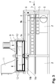
- a device for heat treatment is designed here as a clamping frame 1.
- This is composed of a plurality of here six chambers 2, which are constructed substantially the same.
- a textile web 3 in the direction of arrow 4 can be transported and guided by means of transport chains and clips.
- Each of the chambers 2 comprises means for blowing treatment gas onto the web 3, at least consisting of nozzle boxes 5, which are arranged below and above the web 3, a circulating air blower, means for heating the treatment gas and means for guiding and regulating the recycled treatment gas (Circulating air).
- the clamping frame 1 is largely surrounded by a housing 6; on an input side of the clamping frame 1, an input slot for the web 3 and an exit side an exit slot is arranged.
- the clamping frame 1 further comprises means for supplying fresh air and means for discharging exhaust air.
- a heat exchanger in the form of a heat wheel 7 is arranged.
- the means for supplying the fresh air comprise a fresh air blower 8, the suction side of which communicates with ambient air.
- a pressure side of the fresh air blower 8 is connected to the heat wheel 7 and then to a first channel 9.
- the first channel 9 is arranged in a ceiling region of a first of the chambers 2.1 in the transport direction.
- the first channel 9 is divided into two first sub-channels 9a, 9b of rectangular cross section, which extend parallel to the transport direction and are connected at the rear ends by a first connection 9c of rectangular cross-section.
- the first sub-channels 9a, 9b and the first connection 9c form a U in plan view, that is, the first channel 9 is thus U-shaped overall in plan view.
- the first connection 9c is partially open at the top; the housing 6, more precisely a cover of the housing 6, has in the plan view congruent with the opening of the first connection 9c a continuous first recess, so that the fresh air from the fresh air blower 8 through the heat wheel 7 in the first channel 9 can be conveyed.
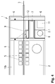
- the means for discharging the exhaust air comprise a second channel 10 which extends over the length of the clamping frame 1 with the exception of the first chamber 2.1.
- the second channel 10 is indirectly connected to a suction side of an exhaust fan 11, whose pressure side is connected to a chimney.
- the second channel 10 is divided into two second sub-channels 10a, 10b with rectangular cross-sections which extend parallel to the transport direction and are connected at the front ends by a second connection 10c of rectangular cross-section.
- the second sub-channels 10a, 10b and the second connection 10c form an elevated U in plan view, that is, the second channel 10 is U-shaped overall in plan view.
- the second connection 10c is open at the top; the housing 6 has in plan view congruent with the opening of the second connection 10c on a continuous second recess, so that the exhaust air from the exhaust fan 11 from the second channel 10 through the heat wheel 7 is conveyed into the chimney. So that the exhaust air can be withdrawn from each of the chambers 2, corresponding suction openings are introduced into the chambers 2 in the second sub-channels 10a, 10b.
- One size of these suction openings is variable by means of flaps or slides.
- the drivable heat wheel 7 is arranged on the housing 6 such that it can be rotated about a vertical axis.
- a housing 12 of the heat wheel 7 is connected with its lower side to the compounds 9 c, 10 c so tightly that flows of fresh air and the exhaust air through the corresponding channels 9, 10, the heat wheel 7 and the fans 8, 11 flow.
- the fans 8, 11 are connected so that from the first connection 9c through the heat wheel 7 there is a flow connection to the pressure side of the fresh air blower 8 and from the second connection 10c through the heat wheel 7 a flow connection to the suction side the exhaust fan 11.
- the housing 12 is thermally insulated.
- the heat wheel 7 is formed in a known manner. It comprises a centric shaft, are attached to the radial boundary webs; on its outer circumference, the heat wheel is enclosed by a ring which is attached to the boundary webs.
- the heat wheel 7 is supported on its outer periphery in the enclosure 12. Between the boundary webs and the ring material is attached, which has favorable properties in terms of heat absorption, storage and delivery.
- the shaft is rotatably mounted and connected to a drive.
- the heat wheel 7 is associated with a cleaning device, e.g. operated with compressed air and / or water at high pressure.
- the housing 12 has a drain line for condensate from the exhaust air and cleaning fluid.
- means for at least one-sided lifting of the heat wheel 7 including the enclosure 12 are arranged.
- the fans 8, 11 are arranged in the immediate vicinity of the heat wheel 7, so that only short lines are required here.
- the web 3 is transported by the transport chains through the chambers 2 of the clamping frame 1.
- uniformly tempered treatment gas here air
- a predetermined amount of exhaust air is withdrawn into the second channel 10.
- a corresponding supply air quantity is withdrawn from one of the chambers 2, which is arranged directly upstream in the transport direction.
- the first chamber 2.1 the fresh air is supplied.
- the exhaust air is sucked with the exhaust fan 11 through the heat wheel 7 from the second channel 10.
- the exhaust air releases a substantial part of its heat to the material of the heat wheel 7, which is stored here.
- the thus cooled exhaust air is discharged through the chimney to the outside.
- the fresh air blower 8 sucks in ambient air as fresh air and promotes it through the heat wheel 7 and the first channel 9 in the first chamber 2.
- the fresh air takes in this case from the heat wheel 7, the heat and is preheated.
- the heat wheel 7 Because the heat wheel 7 is rotated, its segments heated by the exhaust air are continuously brought into the area through which the fresh air flows, while the segments cooled by the fresh air pass into the area through which the exhaust air flows. In this way, there is an effective heat transfer from the exhaust air to the fresh air.
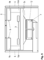
- the first channel 9 is executed here only as the first connection 9c, which is arranged directly above the heat wheel 7 on the housing 12, extends over a width of the web 3 and has nozzle openings for inflating the preheated fresh air to the web 3.
- the first sub-channels 9a, 9b omitted here.
- the fresh air blower 8 is arranged below the heat wheel 7.
- An intake port leads from the fresh air blower 8 to a passage in the housing 6.
- the second connection 10c of the second channel 10 is arranged parallel to the first connection 9c on the enclosure 12.
- Each of the second sub-channels 10a, 10b is connected to the second connection 10c by means of a substantially vertical connecting piece 10d, which is also a component of the second channel 10.
- the exhaust fan 11 is arranged next to the fresh air blower 8 below the heat wheel 7.
- a discharge nozzle of the exhaust fan 11 leads to the chimney.
- a part of the pressure nozzle is designed as a trough for collecting and draining condensate and cleaning fluids with a drain.
- two heat wheels 7, two fresh air blower 8, two first channels 9 and two exhaust fans 11 are arranged.
- a first of the heat wheels 7 is arranged as described above in the region of the first and the second chamber 2 on the housing 6 or in the first chamber 2.1 in the housing 6.
- a second of the heat wheels 7 is arranged substantially mirror-symmetrically in the region of a penultimate and a last of the chambers 2.
- a second of the first channels 9 is formed corresponding to that of the first chamber 2.1 in the last chamber 2.6.
- the second channel 10 has at its two ends the connection 10c.
- the preheated in the heat wheels 7 fresh air is conveyed separately by means of the two fresh air blower 8 in the first chamber 21 and in the last chamber 2.6.
- the exhaust air is distributed in a predetermined ratio to the two heat wheels 7.
Landscapes
- Engineering & Computer Science (AREA)
- Mechanical Engineering (AREA)
- General Engineering & Computer Science (AREA)
- Life Sciences & Earth Sciences (AREA)
- Sustainable Development (AREA)
- Textile Engineering (AREA)
- Treatment Of Fiber Materials (AREA)
Claims (7)
- Dispositif pour le traitement thermique d'une bande textile, comprenant :un boîtier (6),des moyens pour le guidage de la bande (3) dans le boîtier (6),des moyens pour l'insufflation de gaz de traitement réchauffé sur la bande (3),dans lequel un premier canal (9) est agencé pour l'amenée d'air frais qui est au moins une partie du gaz de traitement, et dans lequel un second canal (10) est agencé pour la dérivation de gaz d'échappement,et au moins une roue thermique (7) pour le préchauffage de l'air frais à l'aide du gaz d'échappement, dans lequel la roue thermique (7) est raccordée directement à des côtés chauds des canaux (9, 10) pour l'air frais et pour le gaz d'échappement, dans lequel les côtés chauds des canaux (9, 10) sont guidés exclusivement dans le boîtier (6).
- Dispositif selon la revendication 1, caractérisé en ce que chacun des canaux (9, 10) est divisé en deux canaux partiels espacés (9a, 9b, 10a, 10b) qui sont reliés en forme de U sur les extrémités où le premier canal (9) et le second canal (10) sont contigus, séparément pour chacun des canaux (9, 10).
- Dispositif selon la revendication 2, caractérisé en ce que la roue thermique (7) est agencée directement sur les liaisons (9c, 10c) des canaux (9, 10), dans lequel les liaisons (9c, 10c) sont ouvertes vers la roue thermique (7) et raccordées de manière étanche sur son enceinte (12).
- Dispositif selon l'une quelconque des revendications 1 à 3, caractérisé en ce que le premier canal (9) est associé à une première chambre (2.1) du dispositif.
- Dispositif selon l'une quelconque des revendications 1 à 4, caractérisé en ce que la roue thermique (7) est agencée au-dessus de la bande (3) dans la zone d'un plafond du boîtier (6).
- Dispositif selon l'une quelconque des revendications 1 à 4, caractérisé en ce que la roue thermique (7) est agencée sous la bande (3) dans le boîtier (6).
- Dispositif selon l'une quelconque des revendications 1 à 6, caractérisé en ce que la roue thermique (7) est logée de manière rotative autour d'un arbre perpendiculaire.
Applications Claiming Priority (2)
| Application Number | Priority Date | Filing Date | Title |
|---|---|---|---|
| DE102010033033A DE102010033033B3 (de) | 2010-08-02 | 2010-08-02 | Vorrichtung zur Wärmebehandlung einer textilen Warenbahn |
| PCT/EP2011/062257 WO2012016814A1 (fr) | 2010-08-02 | 2011-07-18 | Dispositif de traitement thermique d'une bande de matière textile |
Publications (2)
| Publication Number | Publication Date |
|---|---|
| EP2601467A1 EP2601467A1 (fr) | 2013-06-12 |
| EP2601467B1 true EP2601467B1 (fr) | 2016-11-16 |
Family
ID=44628730
Family Applications (1)
| Application Number | Title | Priority Date | Filing Date |
|---|---|---|---|
| EP11733846.7A Active EP2601467B1 (fr) | 2010-08-02 | 2011-07-18 | Dispositif de traitement thermique d'une bande de matière textile |
Country Status (8)
| Country | Link |
|---|---|
| EP (1) | EP2601467B1 (fr) |
| KR (1) | KR101492912B1 (fr) |
| CN (1) | CN102971598B (fr) |
| BR (1) | BR112013002635A2 (fr) |
| DE (1) | DE102010033033B3 (fr) |
| ES (1) | ES2616260T3 (fr) |
| HK (1) | HK1183093A1 (fr) |
| WO (1) | WO2012016814A1 (fr) |
Families Citing this family (4)
| Publication number | Priority date | Publication date | Assignee | Title |
|---|---|---|---|---|
| DE102014200751A1 (de) * | 2014-01-17 | 2015-07-23 | Robert Bosch Gmbh | Heißlufttunnel |
| CN105066623A (zh) * | 2015-08-20 | 2015-11-18 | 孙德敏 | 松式烘干机废气利用方法及装置 |
| DE102016109415A1 (de) * | 2016-05-23 | 2017-11-23 | Trützschler GmbH + Co KG Textilmaschinenfabrik | Trocknereinrichtung und Trockner für eine textile Warenbahn mit einer verbesserten Einrichtung zur Wärmeeinbringung |
| CN114505322B (zh) * | 2022-01-18 | 2023-09-26 | 河南车邦汽车用品制造有限公司 | 一种毛毯边角料回收系统及方法 |
Family Cites Families (10)
| Publication number | Priority date | Publication date | Assignee | Title |
|---|---|---|---|---|
| US4092100A (en) * | 1976-09-17 | 1978-05-30 | Granco Equipment, Inc. | Drying oven |
| DE2751284A1 (de) * | 1977-11-16 | 1979-05-17 | Bosch Siemens Hausgeraete | In ein gehaeuse eingebauter waeschetrockner |
| US4270283A (en) * | 1979-01-10 | 1981-06-02 | Ellis James F | Air recycling apparatus for drying a textile web |
| DE3151074A1 (de) * | 1981-12-23 | 1983-07-28 | A. Monforts GmbH & Co, 4050 Mönchengladbach | "heissbehandlungsmaschine" |
| DE3312226A1 (de) * | 1983-04-05 | 1984-10-11 | Babcock Textilmaschinen GmbH, 2105 Seevetal | Anordnung zur waermebehandlung laufender warenbahnen |
| DE3511950C3 (de) * | 1985-04-02 | 2000-04-06 | Babcock Textilmasch | Vorrichtung zum Trocknen von durchlaufenden Gewebe- und Gewirkebahnen oder dergleichen |
| US5915340A (en) * | 1996-10-02 | 1999-06-29 | Abb Air Preheater Inc. | Variable sector plate quad sector air preheater |
| JP3866919B2 (ja) * | 1998-05-07 | 2007-01-10 | メグテック・システムズ・インコーポレーテッド | 再生式熱源完全統合型ウェブ乾燥機 |
| DE29823493U1 (de) * | 1998-06-30 | 1999-07-01 | Babcock Textilmasch | Umlufttrockner |
| DE10333483B4 (de) * | 2003-07-22 | 2008-11-27 | Moenus Textilmaschinen Gmbh | Verfahren zur Wärmebehandlung einer Warenbahn und Behandlungsvorrichtung |
-
2010
- 2010-08-02 DE DE102010033033A patent/DE102010033033B3/de not_active Expired - Fee Related
-
2011
- 2011-07-18 EP EP11733846.7A patent/EP2601467B1/fr active Active
- 2011-07-18 CN CN201180031322.7A patent/CN102971598B/zh not_active Expired - Fee Related
- 2011-07-18 WO PCT/EP2011/062257 patent/WO2012016814A1/fr active Application Filing
- 2011-07-18 BR BR112013002635A patent/BR112013002635A2/pt not_active Application Discontinuation
- 2011-07-18 ES ES11733846.7T patent/ES2616260T3/es active Active
- 2011-07-18 KR KR20127031816A patent/KR101492912B1/ko active IP Right Grant
-
2013
- 2013-09-11 HK HK13110488A patent/HK1183093A1/xx not_active IP Right Cessation
Also Published As
| Publication number | Publication date |
|---|---|
| EP2601467A1 (fr) | 2013-06-12 |
| DE102010033033B3 (de) | 2012-01-05 |
| HK1183093A1 (en) | 2013-12-13 |
| WO2012016814A1 (fr) | 2012-02-09 |
| KR101492912B1 (ko) | 2015-02-12 |
| KR20130041811A (ko) | 2013-04-25 |
| CN102971598A (zh) | 2013-03-13 |
| BR112013002635A2 (pt) | 2017-12-05 |
| ES2616260T3 (es) | 2017-06-12 |
| CN102971598B (zh) | 2015-07-08 |
Similar Documents
| Publication | Publication Date | Title |
|---|---|---|
| EP0712481B1 (fr) | Procede et dispositif de sechage de panneaux | |
| EP0706021B1 (fr) | Séchoir pour une installation de peinture | |
| DE10125771C1 (de) | Trockner | |
| WO1995003517A1 (fr) | Procede et sechoir a air chaud pour secher des surfaces recouvertes d'un revetement | |
| EP3504363A1 (fr) | Four d'oxydation | |
| DE102005061973A1 (de) | Trockner | |
| EP1208341A1 (fr) | Sechoir de peinture et dispositif de sechage de peinture | |
| EP2601467B1 (fr) | Dispositif de traitement thermique d'une bande de matière textile | |
| CH652199A5 (de) | Vorrichtung zur entfernung von feuchtigkeit aus einem waessrigen schlamm und verfahren zum betrieb der vorrichtung. | |
| WO2017041774A1 (fr) | Dispositif de traitement de pièces métalliques avec du gaz de refroidissement | |
| DE1460709C3 (de) | Siebtrommeltrockner Ausscheidung aus 1281992 | |
| DE19858839A1 (de) | Verfahren und Vorrichtung zum Wärmebehandeln einer durchlaufenden Warenbahn durch Aufblasen von Dampf | |
| EP0486712B1 (fr) | Installation pour le traitement superficiel d'articles | |
| DE2607504A1 (de) | Vorrichtung zum trocknen von duennen materialien in stuecken oder bahnen im durchlauf | |
| DE10150041B4 (de) | Austrag-Kühleinrichtung für eine Druckmaschine | |
| DE2833119A1 (de) | Vorrichtung zum kaschieren von werkstuecken | |
| EP3719430A1 (fr) | Installation de séchage continu et procédé de séchage de pièces | |
| EP0971191A2 (fr) | Procédé et dispositif pour traiter des objets par un gaz chauffé | |
| DE102013223030B4 (de) | Backofen und Nachrüstsatz für Backöfen | |
| WO2007124827A1 (fr) | Finisseur à tunnel pour le traitement de pièces à usiner textiles comme finisseur plat | |
| DE102016223041A1 (de) | Backofen | |
| DD207113A3 (de) | Heissmuldenmangel, insbesondere mehrmuldenmangel | |
| DE2137377A1 (de) | Siebtrommel-trockeneinrichtung | |
| DE102006019152A1 (de) | Trocknereinheit sowie Trockner mit einer Mehrzahl solcher Einheiten | |
| DE2421723C2 (de) | Trocknungsvorrichtung |
Legal Events
| Date | Code | Title | Description |
|---|---|---|---|
| PUAI | Public reference made under article 153(3) epc to a published international application that has entered the european phase |
Free format text: ORIGINAL CODE: 0009012 |
|
| 17P | Request for examination filed |
Effective date: 20130304 |
|
| AK | Designated contracting states |
Kind code of ref document: A1 Designated state(s): AL AT BE BG CH CY CZ DE DK EE ES FI FR GB GR HR HU IE IS IT LI LT LU LV MC MK MT NL NO PL PT RO RS SE SI SK SM TR |
|
| DAX | Request for extension of the european patent (deleted) | ||
| GRAP | Despatch of communication of intention to grant a patent |
Free format text: ORIGINAL CODE: EPIDOSNIGR1 |
|
| INTG | Intention to grant announced |
Effective date: 20160721 |
|
| GRAS | Grant fee paid |
Free format text: ORIGINAL CODE: EPIDOSNIGR3 |
|
| GRAA | (expected) grant |
Free format text: ORIGINAL CODE: 0009210 |
|
| AK | Designated contracting states |
Kind code of ref document: B1 Designated state(s): AL AT BE BG CH CY CZ DE DK EE ES FI FR GB GR HR HU IE IS IT LI LT LU LV MC MK MT NL NO PL PT RO RS SE SI SK SM TR |
|
| REG | Reference to a national code |
Ref country code: GB Ref legal event code: FG4D Free format text: NOT ENGLISH |
|
| REG | Reference to a national code |
Ref country code: CH Ref legal event code: EP |
|
| REG | Reference to a national code |
Ref country code: IE Ref legal event code: FG4D Free format text: LANGUAGE OF EP DOCUMENT: GERMAN |
|
| REG | Reference to a national code |
Ref country code: AT Ref legal event code: REF Ref document number: 846321 Country of ref document: AT Kind code of ref document: T Effective date: 20161215 |
|
| REG | Reference to a national code |
Ref country code: DE Ref legal event code: R096 Ref document number: 502011011154 Country of ref document: DE |
|
| REG | Reference to a national code |
Ref country code: DE Ref legal event code: R096 Ref document number: 502011011154 Country of ref document: DE |
|
| PG25 | Lapsed in a contracting state [announced via postgrant information from national office to epo] |
Ref country code: LV Free format text: LAPSE BECAUSE OF FAILURE TO SUBMIT A TRANSLATION OF THE DESCRIPTION OR TO PAY THE FEE WITHIN THE PRESCRIBED TIME-LIMIT Effective date: 20161116 |
|
| REG | Reference to a national code |
Ref country code: NL Ref legal event code: MP Effective date: 20161116 |
|
| REG | Reference to a national code |
Ref country code: LT Ref legal event code: MG4D |
|
| PG25 | Lapsed in a contracting state [announced via postgrant information from national office to epo] |
Ref country code: NO Free format text: LAPSE BECAUSE OF FAILURE TO SUBMIT A TRANSLATION OF THE DESCRIPTION OR TO PAY THE FEE WITHIN THE PRESCRIBED TIME-LIMIT Effective date: 20170216 Ref country code: NL Free format text: LAPSE BECAUSE OF FAILURE TO SUBMIT A TRANSLATION OF THE DESCRIPTION OR TO PAY THE FEE WITHIN THE PRESCRIBED TIME-LIMIT Effective date: 20161116 Ref country code: SE Free format text: LAPSE BECAUSE OF FAILURE TO SUBMIT A TRANSLATION OF THE DESCRIPTION OR TO PAY THE FEE WITHIN THE PRESCRIBED TIME-LIMIT Effective date: 20161116 Ref country code: LT Free format text: LAPSE BECAUSE OF FAILURE TO SUBMIT A TRANSLATION OF THE DESCRIPTION OR TO PAY THE FEE WITHIN THE PRESCRIBED TIME-LIMIT Effective date: 20161116 Ref country code: GR Free format text: LAPSE BECAUSE OF FAILURE TO SUBMIT A TRANSLATION OF THE DESCRIPTION OR TO PAY THE FEE WITHIN THE PRESCRIBED TIME-LIMIT Effective date: 20170217 |
|
| PG25 | Lapsed in a contracting state [announced via postgrant information from national office to epo] |
Ref country code: RS Free format text: LAPSE BECAUSE OF FAILURE TO SUBMIT A TRANSLATION OF THE DESCRIPTION OR TO PAY THE FEE WITHIN THE PRESCRIBED TIME-LIMIT Effective date: 20161116 Ref country code: HR Free format text: LAPSE BECAUSE OF FAILURE TO SUBMIT A TRANSLATION OF THE DESCRIPTION OR TO PAY THE FEE WITHIN THE PRESCRIBED TIME-LIMIT Effective date: 20161116 Ref country code: PT Free format text: LAPSE BECAUSE OF FAILURE TO SUBMIT A TRANSLATION OF THE DESCRIPTION OR TO PAY THE FEE WITHIN THE PRESCRIBED TIME-LIMIT Effective date: 20170316 Ref country code: PL Free format text: LAPSE BECAUSE OF FAILURE TO SUBMIT A TRANSLATION OF THE DESCRIPTION OR TO PAY THE FEE WITHIN THE PRESCRIBED TIME-LIMIT Effective date: 20161116 Ref country code: FI Free format text: LAPSE BECAUSE OF FAILURE TO SUBMIT A TRANSLATION OF THE DESCRIPTION OR TO PAY THE FEE WITHIN THE PRESCRIBED TIME-LIMIT Effective date: 20161116 |
|
| REG | Reference to a national code |
Ref country code: ES Ref legal event code: FG2A Ref document number: 2616260 Country of ref document: ES Kind code of ref document: T3 Effective date: 20170612 |
|
| PG25 | Lapsed in a contracting state [announced via postgrant information from national office to epo] |
Ref country code: DK Free format text: LAPSE BECAUSE OF FAILURE TO SUBMIT A TRANSLATION OF THE DESCRIPTION OR TO PAY THE FEE WITHIN THE PRESCRIBED TIME-LIMIT Effective date: 20161116 Ref country code: EE Free format text: LAPSE BECAUSE OF FAILURE TO SUBMIT A TRANSLATION OF THE DESCRIPTION OR TO PAY THE FEE WITHIN THE PRESCRIBED TIME-LIMIT Effective date: 20161116 Ref country code: RO Free format text: LAPSE BECAUSE OF FAILURE TO SUBMIT A TRANSLATION OF THE DESCRIPTION OR TO PAY THE FEE WITHIN THE PRESCRIBED TIME-LIMIT Effective date: 20161116 Ref country code: CZ Free format text: LAPSE BECAUSE OF FAILURE TO SUBMIT A TRANSLATION OF THE DESCRIPTION OR TO PAY THE FEE WITHIN THE PRESCRIBED TIME-LIMIT Effective date: 20161116 Ref country code: SK Free format text: LAPSE BECAUSE OF FAILURE TO SUBMIT A TRANSLATION OF THE DESCRIPTION OR TO PAY THE FEE WITHIN THE PRESCRIBED TIME-LIMIT Effective date: 20161116 |
|
| REG | Reference to a national code |
Ref country code: DE Ref legal event code: R097 Ref document number: 502011011154 Country of ref document: DE |
|
| PG25 | Lapsed in a contracting state [announced via postgrant information from national office to epo] |
Ref country code: BG Free format text: LAPSE BECAUSE OF FAILURE TO SUBMIT A TRANSLATION OF THE DESCRIPTION OR TO PAY THE FEE WITHIN THE PRESCRIBED TIME-LIMIT Effective date: 20170216 Ref country code: SM Free format text: LAPSE BECAUSE OF FAILURE TO SUBMIT A TRANSLATION OF THE DESCRIPTION OR TO PAY THE FEE WITHIN THE PRESCRIBED TIME-LIMIT Effective date: 20161116 |
|
| PLBE | No opposition filed within time limit |
Free format text: ORIGINAL CODE: 0009261 |
|
| STAA | Information on the status of an ep patent application or granted ep patent |
Free format text: STATUS: NO OPPOSITION FILED WITHIN TIME LIMIT |
|
| 26N | No opposition filed |
Effective date: 20170817 |
|
| PG25 | Lapsed in a contracting state [announced via postgrant information from national office to epo] |
Ref country code: SI Free format text: LAPSE BECAUSE OF FAILURE TO SUBMIT A TRANSLATION OF THE DESCRIPTION OR TO PAY THE FEE WITHIN THE PRESCRIBED TIME-LIMIT Effective date: 20161116 |
|
| REG | Reference to a national code |
Ref country code: CH Ref legal event code: PL |
|
| GBPC | Gb: european patent ceased through non-payment of renewal fee |
Effective date: 20170718 |
|
| REG | Reference to a national code |
Ref country code: IE Ref legal event code: MM4A |
|
| REG | Reference to a national code |
Ref country code: FR Ref legal event code: ST Effective date: 20180330 |
|
| PG25 | Lapsed in a contracting state [announced via postgrant information from national office to epo] |
Ref country code: IE Free format text: LAPSE BECAUSE OF NON-PAYMENT OF DUE FEES Effective date: 20170718 Ref country code: LI Free format text: LAPSE BECAUSE OF NON-PAYMENT OF DUE FEES Effective date: 20170731 Ref country code: CH Free format text: LAPSE BECAUSE OF NON-PAYMENT OF DUE FEES Effective date: 20170731 Ref country code: GB Free format text: LAPSE BECAUSE OF NON-PAYMENT OF DUE FEES Effective date: 20170718 |
|
| PG25 | Lapsed in a contracting state [announced via postgrant information from national office to epo] |
Ref country code: FR Free format text: LAPSE BECAUSE OF NON-PAYMENT OF DUE FEES Effective date: 20170731 |
|
| REG | Reference to a national code |
Ref country code: BE Ref legal event code: MM Effective date: 20170731 |
|
| PG25 | Lapsed in a contracting state [announced via postgrant information from national office to epo] |
Ref country code: LU Free format text: LAPSE BECAUSE OF NON-PAYMENT OF DUE FEES Effective date: 20170718 |
|
| PG25 | Lapsed in a contracting state [announced via postgrant information from national office to epo] |
Ref country code: BE Free format text: LAPSE BECAUSE OF NON-PAYMENT OF DUE FEES Effective date: 20170731 |
|
| REG | Reference to a national code |
Ref country code: AT Ref legal event code: MM01 Ref document number: 846321 Country of ref document: AT Kind code of ref document: T Effective date: 20170718 |
|
| PG25 | Lapsed in a contracting state [announced via postgrant information from national office to epo] |
Ref country code: MT Free format text: LAPSE BECAUSE OF FAILURE TO SUBMIT A TRANSLATION OF THE DESCRIPTION OR TO PAY THE FEE WITHIN THE PRESCRIBED TIME-LIMIT Effective date: 20161116 |
|
| PG25 | Lapsed in a contracting state [announced via postgrant information from national office to epo] |
Ref country code: AT Free format text: LAPSE BECAUSE OF NON-PAYMENT OF DUE FEES Effective date: 20170718 |
|
| PG25 | Lapsed in a contracting state [announced via postgrant information from national office to epo] |
Ref country code: HU Free format text: LAPSE BECAUSE OF FAILURE TO SUBMIT A TRANSLATION OF THE DESCRIPTION OR TO PAY THE FEE WITHIN THE PRESCRIBED TIME-LIMIT; INVALID AB INITIO Effective date: 20110718 Ref country code: MC Free format text: LAPSE BECAUSE OF FAILURE TO SUBMIT A TRANSLATION OF THE DESCRIPTION OR TO PAY THE FEE WITHIN THE PRESCRIBED TIME-LIMIT Effective date: 20161116 |
|
| PG25 | Lapsed in a contracting state [announced via postgrant information from national office to epo] |
Ref country code: CY Free format text: LAPSE BECAUSE OF NON-PAYMENT OF DUE FEES Effective date: 20161116 |
|
| PG25 | Lapsed in a contracting state [announced via postgrant information from national office to epo] |
Ref country code: MK Free format text: LAPSE BECAUSE OF FAILURE TO SUBMIT A TRANSLATION OF THE DESCRIPTION OR TO PAY THE FEE WITHIN THE PRESCRIBED TIME-LIMIT Effective date: 20161116 |
|
| PG25 | Lapsed in a contracting state [announced via postgrant information from national office to epo] |
Ref country code: AL Free format text: LAPSE BECAUSE OF FAILURE TO SUBMIT A TRANSLATION OF THE DESCRIPTION OR TO PAY THE FEE WITHIN THE PRESCRIBED TIME-LIMIT Effective date: 20161116 Ref country code: IS Free format text: LAPSE BECAUSE OF FAILURE TO SUBMIT A TRANSLATION OF THE DESCRIPTION OR TO PAY THE FEE WITHIN THE PRESCRIBED TIME-LIMIT Effective date: 20170316 |
|
| PGFP | Annual fee paid to national office [announced via postgrant information from national office to epo] |
Ref country code: TR Payment date: 20200717 Year of fee payment: 10 Ref country code: ES Payment date: 20200804 Year of fee payment: 10 |
|
| PGFP | Annual fee paid to national office [announced via postgrant information from national office to epo] |
Ref country code: IT Payment date: 20200731 Year of fee payment: 10 |
|
| PG25 | Lapsed in a contracting state [announced via postgrant information from national office to epo] |
Ref country code: IT Free format text: LAPSE BECAUSE OF NON-PAYMENT OF DUE FEES Effective date: 20210718 |
|
| REG | Reference to a national code |
Ref country code: ES Ref legal event code: FD2A Effective date: 20221003 |
|
| PG25 | Lapsed in a contracting state [announced via postgrant information from national office to epo] |
Ref country code: ES Free format text: LAPSE BECAUSE OF NON-PAYMENT OF DUE FEES Effective date: 20210719 |
|
| PGFP | Annual fee paid to national office [announced via postgrant information from national office to epo] |
Ref country code: DE Payment date: 20230718 Year of fee payment: 13 |
|
| REG | Reference to a national code |
Ref country code: DE Ref legal event code: R082 Ref document number: 502011011154 Country of ref document: DE Representative=s name: PAUL & ALBRECHT PATENTANWAELTE PARTG MBB, DE |