EP2601112B1 - Schraubverschluss mit flexband - Google Patents
Schraubverschluss mit flexband Download PDFInfo
- Publication number
- EP2601112B1 EP2601112B1 EP11741200.7A EP11741200A EP2601112B1 EP 2601112 B1 EP2601112 B1 EP 2601112B1 EP 11741200 A EP11741200 A EP 11741200A EP 2601112 B1 EP2601112 B1 EP 2601112B1
- Authority
- EP
- European Patent Office
- Prior art keywords
- flexband
- portions
- section
- wall
- folded
- Prior art date
- Legal status (The legal status is an assumption and is not a legal conclusion. Google has not performed a legal analysis and makes no representation as to the accuracy of the status listed.)
- Not-in-force
Links
Images

Classifications
-
- B—PERFORMING OPERATIONS; TRANSPORTING
- B65—CONVEYING; PACKING; STORING; HANDLING THIN OR FILAMENTARY MATERIAL
- B65D—CONTAINERS FOR STORAGE OR TRANSPORT OF ARTICLES OR MATERIALS, e.g. BAGS, BARRELS, BOTTLES, BOXES, CANS, CARTONS, CRATES, DRUMS, JARS, TANKS, HOPPERS, FORWARDING CONTAINERS; ACCESSORIES, CLOSURES, OR FITTINGS THEREFOR; PACKAGING ELEMENTS; PACKAGES
- B65D41/00—Caps, e.g. crown caps or crown seals, i.e. members having parts arranged for engagement with the external periphery of a neck or wall defining a pouring opening or discharge aperture; Protective cap-like covers for closure members, e.g. decorative covers of metal foil or paper
- B65D41/32—Caps or cap-like covers with lines of weakness, tearing-strips, tags, or like opening or removal devices, e.g. to facilitate formation of pouring openings
- B65D41/34—Threaded or like caps or cap-like covers provided with tamper elements formed in, or attached to, the closure skirt
- B65D41/3423—Threaded or like caps or cap-like covers provided with tamper elements formed in, or attached to, the closure skirt with flexible tabs, or elements rotated from a non-engaging to an engaging position, formed on the tamper element or in the closure skirt
- B65D41/3428—Threaded or like caps or cap-like covers provided with tamper elements formed in, or attached to, the closure skirt with flexible tabs, or elements rotated from a non-engaging to an engaging position, formed on the tamper element or in the closure skirt the tamper element being integrally connected to the closure by means of bridges
-
- B—PERFORMING OPERATIONS; TRANSPORTING
- B65—CONVEYING; PACKING; STORING; HANDLING THIN OR FILAMENTARY MATERIAL
- B65D—CONTAINERS FOR STORAGE OR TRANSPORT OF ARTICLES OR MATERIALS, e.g. BAGS, BARRELS, BOTTLES, BOXES, CANS, CARTONS, CRATES, DRUMS, JARS, TANKS, HOPPERS, FORWARDING CONTAINERS; ACCESSORIES, CLOSURES, OR FITTINGS THEREFOR; PACKAGING ELEMENTS; PACKAGES
- B65D41/00—Caps, e.g. crown caps or crown seals, i.e. members having parts arranged for engagement with the external periphery of a neck or wall defining a pouring opening or discharge aperture; Protective cap-like covers for closure members, e.g. decorative covers of metal foil or paper
- B65D41/32—Caps or cap-like covers with lines of weakness, tearing-strips, tags, or like opening or removal devices, e.g. to facilitate formation of pouring openings
- B65D41/34—Threaded or like caps or cap-like covers provided with tamper elements formed in, or attached to, the closure skirt
- B65D41/348—Threaded or like caps or cap-like covers provided with tamper elements formed in, or attached to, the closure skirt the tamper element being rolled or pressed to conform to the shape of the container, e.g. metallic closures
-
- B—PERFORMING OPERATIONS; TRANSPORTING
- B65—CONVEYING; PACKING; STORING; HANDLING THIN OR FILAMENTARY MATERIAL
- B65D—CONTAINERS FOR STORAGE OR TRANSPORT OF ARTICLES OR MATERIALS, e.g. BAGS, BARRELS, BOTTLES, BOXES, CANS, CARTONS, CRATES, DRUMS, JARS, TANKS, HOPPERS, FORWARDING CONTAINERS; ACCESSORIES, CLOSURES, OR FITTINGS THEREFOR; PACKAGING ELEMENTS; PACKAGES
- B65D41/00—Caps, e.g. crown caps or crown seals, i.e. members having parts arranged for engagement with the external periphery of a neck or wall defining a pouring opening or discharge aperture; Protective cap-like covers for closure members, e.g. decorative covers of metal foil or paper
- B65D41/32—Caps or cap-like covers with lines of weakness, tearing-strips, tags, or like opening or removal devices, e.g. to facilitate formation of pouring openings
- B65D41/46—Snap-on caps or cap-like covers
- B65D41/48—Snap-on caps or cap-like covers non-metallic, e.g. made of paper or plastics
Definitions
- the present invention relates to a screw cap, consisting of a screw cap and a guarantee strip, wherein the screw cap has a top plate with a cylindrical cap coat, which is provided with an internal thread, and wherein the guarantee strip has a flex band and one or more easily tearable elements with the is connected to the lower edge of the cap skirt, wherein the flex band is formed as a continuous circumferential Flexband, which has distributed over its circumference several easily stretchable sections and relatively less easily stretchable sections between them, and wherein the more easily expandable sections a smaller wall cross-section, especially in the folded state have smaller measured in the radial direction wall thickness than the less easily stretchable sections, wherein the sections with the larger wall cross section have an upwardly widening, wedge-shaped cross section, wherein the upper edge of the umg folded Flexbandes includes the most radially inwardly projecting protrusions.
- Such screw caps are, in particular for container mouths or closure bottoms, the diameter of which is 38 mm or less in use.
- a flex-band closure in which more easily stretchable and less easily stretchable portions are joined together in a zigzag configuration, with narrow, in plan view triangular thin-walled portions on one side with the rear edge and on the other side with the front Edge of two adjacent less easily stretchable sections are connected, so that both the more expansible and the less easily stretchable sections vary in their distance from the axis.
- the furthest projecting corner of a less easily stretched portion forms a projection which engages behind a locking ring in the assembled state of the closure, while the remaining part of the less easily stretchable portion does not engage behind the retaining ring on a container neck.
- the hinged part of a guarantee strip which extends during and immediately after production approximately in the axial extension of the cap skirt and an outer guarantee band section, but which folds inwards and upwards (in the direction of the top plate) is and its free end a in the folded state upwardly facing bearing surface which applies when loosening a screw cap to the underside of a retaining ring when it is located on a closure bottom or a corresponding container neck below the mating to the screw external thread.
- Such flexbands are known in a variety of configurations, especially in the form of separate, individually foldable segments and with interruptions, which should facilitate the application of an intact closure and in particular the intact guarantee band on the container neck or a corresponding lower part.
- the free inner diameter of the flex band, which sets in the folded state must be significantly smaller than the outer diameter of the retaining ring on the container neck or closure bottom, which is to engage behind the Flexband.
- the flex band which is connected via a weak point acting as a hinge with the outer portion of the guarantee band, unrolls when acting on an axial force on the free end, specifically when engaging with the underside of the locking ring during unscrewing the screw simply down and folding back into a position in which it essentially forms an axial extension of the outer portion of the guarantee strip and in this way can slide over the retaining ring, it must on the one hand enough rigidity in itself, and it must be in the folded state under a extending relatively acute angle (relative to the cylindrical inner wall of the outer guarantee strap portion) upwards.
- an axial force acts predominantly in the longitudinal direction of the more or less cylindrical or slightly conical wall of the flex belt and exerts on the hinge portion a corresponding axial tensile force on the outer portion of the guarantee band, which is sufficient to rupture the easily breakable connection or connections between The guarantee strip and the lower edge of the screw cap leads.
- a screw cap and its flex band are sufficiently matched in their dimensions to a bottleneck or a corresponding closure bottom, so that the Flexband after applying the screw cap on a container neck or a closure base, if it is below the retaining ring rests against the outer circumference of the container neck, assumes a corresponding position in which the wall of the flex band with the wall of the outer portion of the guarantee strip or with the axis of the closure includes a sufficiently acute angle, which should not exceed 30 ° if possible.
- blow-molded container necks therefore often have significantly greater inaccuracies and typical tolerances of up to ⁇ 0.3% or more.
- This is particularly disadvantageous for large diameters of 35 mm and above, because in such a case screw caps with corresponding flex bands, which are placed on the nominal size of such container necks or closure bottoms, no longer fit exactly to the container necks thus produced.
- screw caps with corresponding flex bands which are placed on the nominal size of such container necks or closure bottoms, no longer fit exactly to the container necks thus produced.
- the effective softening of the diameter of the guarantee strip in the region of the hinge section and the outside diameter of the container neck below the retaining ring is 0.3 mm compared to the corresponding nominal dimension.
- the upper end of the flex band which is the smallest diameter of the flex band and rests with its inner upper edge on the outer surface of the bottle neck, can dodge further inwardly by 0.15 mm (tilting about the hinge portion) than at Compliance with the nominal dimensions.
- the axial length of the flex band from the hinge area to the free end of the order of only a few mm and z. B. 3 mm means a further tilting of the upper portion of the flex band to 0.15 mm inward, since even with compliance with the nominal dimensions of the wall of the flex belt is typically already tilted by up to 20 ° relative to the outer portion of the guarantee strip at more precise consideration of the concrete geometries an increase of the tilt angle (between flex band and axis) by up to 5 °, so that when exerting an axial force on the free end of the flex band, this force implemented to a considerable extent in a force acting perpendicular to the wall of the flex band force component is acting as a bending force with respect to the hinge section and a so-called "unrolling", ie Folding the Flexbandes around the hinge section, can lead.
- a guarantee strip which can be solved by unrolling the Flexbandes of a container neck without the guarantee strip tears from the screw cap, the risk of manipulation of the container contents increased, since then such a state could also be deliberately brought about to replace the container contents and / or change.
- WO00 / 23343 The closest prior art is the WO00 / 23343 considered.
- These less easily stretchable sections are in turn connected by thinner and thus more easily stretchable wall sections, in such a way that the more easily stretchable wall portion is connected on its one side to the radially outer edge of a less easily stretchable portion and on the other Side is connected to the radially inner edge of the adjacent, less easily stretchable portion.
- the present invention has the object to provide a screw with Flexband, which ensures even with larger tolerance deviations between closure and container neck still a safe tearing off the tamperproof and also provides greater tolerance deviations reliability and on the other hand, a grip behind a container locking ring essentially over the entire length of the less easily stretchable sections.
- the extensibility of the easily stretchable sections should be exploited for applying the closure to a container neck.
- the present invention with the subject matter of WO 00/23343 has in common, the easily stretchable and less easily stretched portions are arranged so that the radially outwardly located in the folded state wall of the flex strip (6) defines a cone-shaped circumferential wall portion.
- the cone-shaped circumferential wall section makes it imperative that an increase in the diameter of the flexible band is possible only by stretching the circumferential wall section, as far as such an expansion Everything is ensured by the easily stretchable sections.
- a zigzag arrangement of light and less easily stretchable sections in the case of WO 00/23343 is thereby avoided and the widening in cross-section wedge-shaped sections have substantially the same constant radius to the central axis and can thus rest over its entire length on the underside of a retaining ring.
- the elongation of the more easily stretchable portions provides a greater recoil force than just hinged pivoting between lighter and less easily stretched portions.
- the upper inner edge of the less extensible portions in the folded state of the flex band defines the smallest inner diameter of the flex band, so that this upper inner edge rests against the bottleneck in use below the locking ring.
- the less easily stretchable portions may have radially inwardly projecting projections defining the smallest inner diameter of the folded-over flex band.
- the radially inwardly projecting projections are provided at the upper free end of the flex band.
- triangular or nose-shaped projections are preferred, which form the upper end portion of the less easily stretchable portions and have their maximum radial extent at the free end of the flex band.
- the top of the protrusions then forms part of the surface engaging the underside of a locking ring. It is understood, however, that the projections can also have largely any, other cross-sectional shapes, for example, rectangular or with more complex, polygonal or rounded outlines can be configured.
- the more easily expandable sections are formed by sections having a smaller wall cross-section, in particular by sections which, in the folded-over state, have a smaller wall thickness measured in the radial direction than the remaining, less easily stretched sections.
- These less easily stretchable sections or the sections with the larger wall cross-section have an upwardly extending cross-section, wherein the upper edge of the folded-over Flexband includes the most radially inwardly projecting protrusions.
- the cross-sections mentioned here are always defined by cross-sectional planes which are defined by the axis of the screw cap and a radius extending from the axis.
- a Flexbandes distributed over its circumference several easily stretchable sections and between less easily stretchable sections, which also have radially inwardly projecting projections in the folded state is that such a Flexband is even better suited for capturing larger tolerance deviations .
- a flex band can be designed and manufactured from the outset with a smaller nominal dimension of its inside diameter, wherein this inside diameter of the flex band is the free inside diameter of the flex band, which adjusts itself in the folded-up state of the flex band.
- this inner diameter is defined by the respective inwardly projecting projections of the less easily stretched sections.
- the actual wall of the flex band which is through the connection from the hinge portion through the center of the latter, stands outgoing wall portion is defined, still relatively steep and at a very acute angle or nearly parallel to the outer wall of the guarantee strip or to the axis of the closure.
- the radially inwardly projecting protrusions are designed so that they are comparatively easily deformable and thus facilitate the push-away of the Flexbandes on the retaining ring in addition.
- the radially outboard wall of the flex band in the folded state defines, after the screw cap is seated to a desired pitch, an approximately tapered circumferential wall portion having a relatively acute cone angle corresponding to the angle between the wall of the flex band and the axial direction ,
- the radially outer wall of the flex band can additionally have a radially outwardly slightly thickened bead or bead edge at the upper end of the flex band in addition to this cone-shaped circumferential basic shape.
- the guarantee strip on its inner surface has a corresponding circumferential recess to accommodate this bead.
- the wall of the flex band extends nearly parallel to the outer portion of the guarantee band or parallel to the axial direction. This position is particularly important for the flex band when it is moved over the circlip and is maximally expanded.
- the outer wall of the flex band defined in the folded state, a cone wall or a cone wall as an envelope, expediently defined by the conical angle measured towards the axis.
- directed force when engaging the top of the flex band with the underside of the retaining ring is essential to the steep alignment of the outer wall portions of the flex band to a directed perpendicular to the wall of the flex belt bending force to avoid and to transmit the force predominantly as axial tensile force on the outer guarantee band section.
- a small angle between the conical outer wall of the flex strip and the axis of the screw cap is a good measure and an indication of the functioning of the guarantee strip.
- the thick-walled portions with the radially inwardly projecting projections in the circumferential direction occupy respectively two to ten times the corresponding peripheral portions of a stretchable or thin-walled portion.
- a total of nine more easily expandable sections are provided alternately with less extensible sections, the more easily expandable sections each occupying about one fifth of the peripheral sections each occupied by the less easily stretched sections ,
- the less easily stretchable sections can also be further structured in that, for example, each of the circumferentially lying end portions of the upper edge of the less easily stretchable peripheral portions each have something more pronounced and further radially inwardly projecting nose-shaped projections than the intermediate areas. These end sections can again make up about one-tenth to one-fourth of the corresponding peripheral section.
- the approximately nose-shaped projections have an approximately triangular basic shape, and set against the inside of an already wedge-shaped wall cross-section of the thicker-walled sections. If one already understands the spline of these sections as compared to the profile of the thin-walled, more easily stretchable sections as a projection in the sense of claim 1, one can also describe the cross-sectional profile of the less easily stretchable sections in a preferred embodiment in that the triangular projections inwardly, ie have in the triangle profile, kinked hypotenuse. This results in the upper end portion of the radially inwardly projecting protrusions being given a somewhat more acute cross section, i. the angle between the top of the flex band, which comprises the top of the nose-shaped projections, and the inside surface of the nose-shaped protrusions is still somewhat smaller than without a corresponding inwardly kinked hypotenuse.
- the invention is provided for screw caps whose nominal diameter is at least 35 mm, the advantages are even more pronounced when the nominal diameter of the screw cap is larger, that is in particular at least 50 mm.
- the invention is also directed to the combination of a container and a screw on the container neck screw cap, with a container neck and a molded thereto, the container neck surrounding and flange-like outwardly projecting circlip.
- the object underlying the invention is achieved in that the screw cap has the features of at least one of claims 1 to 11.
- the defined by the less easily stretchable portions of the ready folded folded Flexbandes inner diameter thereof should be smaller than the outer diameter of the bottle neck immediately below the retaining ring, which means that after applying the closure, the Flexband is kept expanded by the bottle neck below the retaining ring and under tension against the neck of the bottle. Furthermore, it is provided in the preferred variant of such a combination that the outer diameter of the bottle neck tapers below the securing ring and with increasing distance from this securing ring.
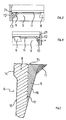
- the screw cap 1 designated overall by 10, consists of a screw cap 1 and a guarantee strip 5.
- the screw cap 1 in turn consists of a substantially flat and circular disk-shaped top plate 2 and an approximately cylindrical cap casing 3, which has an internal thread 4, which is for screwing on the appropriately sized external thread of a container neck is designed.
- a protruding edge which extends upwards from the top plate, but which is of subordinate importance for the present invention.
- the cap casing also has a cylindrical extension 3 ', to which the outer portion 12 of a guarantee band 5 connects via (not shown) easily tearable connections
- the Flexband 6 has a narrow, wedge-shaped cross-section in the lower region and in a region 9 of greater wall thickness. It is understood that this cross-section does not necessarily have to be narrow wedge-shaped, but could also be constant immediately above the hinge area with a uniform wall thickness over the length of time.
- the length or longitudinal direction k can be defined as the shortest connection from the hinge area 13 to the free end with the upper end face 15, in particular in FIG Fig. 2 recognizes the cross section of the flex belt 6 in a more easily stretchable portion 8, starting from the hinge area, a nearly constant, small thickness at the same time has significantly greater length and thus well defines the "longitudinal direction" of the flex belt 6.
- the conical outer wall 16 extends on the one hand in the circumferential direction and on the other hand in the just-defined longitudinal direction.
- the folded-over flex band 6 consists of different sections 8 and 9, the sections 8 having a smaller wall thickness (see sectional drawing of FIGS. 2 and 3 or 5 and 6 ), so that these sections are more easily stretchable due to the cross-sectional geometry than the other sections 9 whose cross-section, for example, in Fig. 3 (or FIG. 5 ) is recognizable.
- the sections 8 and 9 in are particularly well recognizable and distinguishable Fig. 4 , it can be seen that in the embodiment shown here (which also in the Fig.
- the sections 9 in turn still have an inner structure, namely by the circumferentially the ends of the section 9 forming portions or parts even more pronounced radially inwardly projecting, triangular in cross-section projections 11 a, 11 b have.
- the guarantee strip 5 is connected at 7 via easily rupturable elements or via a circumferential, continuous weak point with the lower, expanded edge 3 'of the cap skirt 3.
- the Flexband takes about in the FIGS. 2 and 3 (or FIGS. 5 and 6 ) well-recognizable position and inclination relative to the axis of the closure or with respect to the direction defined by the outer, cylindrical guarantee band portion 12 a.
- the nose-shaped projections 11 and 11a, 11b bear against the outer surface of the (not shown) of the bottle neck below the retaining ring and hold the flex band 6 in the illustrated, relatively upright position, in which the wall 16 and the longitudinal direction of the flex belt 6 below a comparatively acute angle ⁇ to the cylindrical wall of the outer guarantee strap portion 12 extends.
- the tension in the flex band 6 against which it bears against the outside of the bottle neck causes the flex band to slide down to this conical portion of the container neck, leaving a clearly visible distance between the guarantee strip 5 and the optionally screwed back cap remains and indicates that the closure has already been opened at least once.
- the guarantee band meets in intact, d. H. with the screw cap 3 firmly connected state, its function as a guarantee of the integrity of the container contents.
- Fig. 7 the cross section of the flex band is shown enlarged again.
- the more easily stretched, smaller wall thickness portions 8 have a cross section as represented by the left side outer wall 16 and the vertical dashed line 17, and this wall thickness tapers slightly downwardly toward the hinge portion 13 again.
- the longitudinal direction of the flex band in this cross-section is substantially the vertical or wall 16 which extends from the hinge region 13 up to the free end of the flex band 6 defined by the end face 15.
- the sections 9 with greater wall thickness have in addition to the wedge-shaped cross section, which is recognizable between the inner wall 18 and the outer wall 17 and would anyway form a kind of radial projection or a radially inwardly projecting tip at the upper end of the flex belt 6, yet the nose-shaped or triangular in cross-section additional projections 11.
- the wedge-shaped cross-section and the additional projections 11 cause the sections 9 are less easily stretchable than the sections eighth
- the narrow-hatched and the cross-hatched area in FIG. 7 describe as an approximately triangular projection, but which is not exactly triangular, but has an inwardly buckled hypotenuse.
- the nose angle ie the angle between the top 15 of the flex band and the lower or Inner surface 19 of the projection 11, which corresponds to a conical surface with a relatively large cone angle, a little smaller and sharper, causing the tip of the nose-shaped projection 11 to a radially outwardly acting pressure (such as during application and Hinwegbe Anlagens via a retaining ring) inwardly and upwardly relatively easily deformable, pointed lip ausformt.
- These nose-shaped projections 11 attach to the outer surface of a container neck below a retaining ring and can due to their flexibility and their projection relative to the longitudinal section defining wall portion greater tolerance deviations of container necks better than conventional flexbands, since the flexbands in this way with smaller nominal dimensions of their free Inside diameter can be produced and yet can be pushed over a locking ring away and can rest against the container neck.
- the outer guarantee strip section 12 does not have a constant wall thickness, but is somewhat tapered in the upper region, in order to form a recess 21 in which a bead 14, ie an outwardly projecting thickening of the flexible strip 6, is accommodated especially in the moment in which it has to be moved over the retaining ring when applying the closure, in the radial direction to expand sufficiently far, and the flexible, nose-like projections 11, at least then, if they are formed corresponding acute-angled, as described above, contribute due to their correspondingly easier deformability to the fact that the flex band can pass the securing ring intact when applied.
- the more easily stretchable sections 8 contribute to a corresponding radial expansion of the flexible strip 6, which allow an intact passing of the retaining ring.
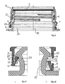
- FIGS. 8 to 10 “Yet another embodiment of the present invention is shown which in all essentials is identical to the embodiments already described, but here shown in section on a bottle neck 20.
- the bottle neck 20 has an external thread 21, onto which the cap 10 is screwed with its internal thread 4.
- the bottleneck has a locking ring 22 below the thread, the outer diameter is again greater than the outer diameter of the thread 21 and the underside, as can be seen in particular in the enlarged cutouts according to the FIGS. 9 and 10 recognizes, substantially flat and perpendicular to the common axis 30 of the bottle neck 20 and the screw cap 10 extends.
- the guarantee strip 5 is still connected via intact elements 7 connected to the lower portion 3 'of the cap skirt, wherein the flex band 6 is completely below the locking ring 22, so that its flat top 17 can come into contact with the flat bottom 24 of the retaining ring when the closure is moved upwards by unscrewing.
- the inwardly projecting projection of the flex band 6 does not overlap with the conical wall portion 23 of the bottle neck 20.
- the apparent overlap is only achieved in the figure in that the cutting plane of the screw cap 10 is slightly offset towards the back through the neck of the bottle.
- the FIGS. 9 and 10 each show enlarged sections of the lower left and right edge of the FIG. 8 , On the right side of the FIG.
- the guarantee strip 5 is shown separated from the lower portion 3 'of the cap skirt 3, ie the easily rupturable fasteners 7 are interrupted or destroyed.
- the flexible band 6 bears against the outside of the conical wall section 23 of the bottle neck under radial tension
- the guarantee strip 5 completely slides downwards until its lower edge rests on an extension of the bottle neck 20, as can be seen in FIG. 10 clearly recognizes.
- the remaining details of the flex band, especially with regard to the changing slightly stretchable and less easily stretched portions are consistent with the embodiments already described, wherein only the shape of the radially inwardly projecting nose-like projections due to an inner Kantenabrundung slightly different from the previously discussed embodiments.
Landscapes
- Engineering & Computer Science (AREA)
- Mechanical Engineering (AREA)
- Closures For Containers (AREA)
Applications Claiming Priority (2)
| Application Number | Priority Date | Filing Date | Title |
|---|---|---|---|
| DE102010039036A DE102010039036A1 (de) | 2010-08-06 | 2010-08-06 | Schraubverschluss mit Flexband |
| PCT/EP2011/063373 WO2012017011A1 (de) | 2010-08-06 | 2011-08-03 | Schraubverschluss mit flexband |
Publications (2)
| Publication Number | Publication Date |
|---|---|
| EP2601112A1 EP2601112A1 (de) | 2013-06-12 |
| EP2601112B1 true EP2601112B1 (de) | 2015-02-25 |
Family
ID=44508438
Family Applications (1)
| Application Number | Title | Priority Date | Filing Date |
|---|---|---|---|
| EP11741200.7A Not-in-force EP2601112B1 (de) | 2010-08-06 | 2011-08-03 | Schraubverschluss mit flexband |
Country Status (7)
| Country | Link |
|---|---|
| US (1) | US8684203B2 (zh) |
| EP (1) | EP2601112B1 (zh) |
| CN (1) | CN103097253B (zh) |
| BR (1) | BR112013001701A2 (zh) |
| DE (1) | DE102010039036A1 (zh) |
| ES (1) | ES2536054T3 (zh) |
| WO (1) | WO2012017011A1 (zh) |
Families Citing this family (6)
| Publication number | Priority date | Publication date | Assignee | Title |
|---|---|---|---|---|
| US20190375558A1 (en) * | 2012-11-01 | 2019-12-12 | Niagara Bottling, Llc. | Extended thread tamper band evidence |
| IT201600080146A1 (it) * | 2016-07-29 | 2018-01-29 | Guala Pack Spa | Chiusura con sigillo di garanzia |
| WO2018171886A1 (en) * | 2017-03-23 | 2018-09-27 | Aptar Freyung Gmbh | Dispensing closure for a fluid container |
| IT201700046734A1 (it) * | 2017-04-28 | 2018-10-28 | Bormioli Pharma S R L | Capsula di sicurezza con bandella |
| IT201900007809A1 (it) * | 2019-05-31 | 2020-12-01 | Sacmi | Tappo per un contenitore, e combinazione di un tappo e di un collo di contenitore. |
| US11059633B2 (en) | 2019-10-31 | 2021-07-13 | Cheer Pack North America | Flip-top closure for container |
Family Cites Families (12)
| Publication number | Priority date | Publication date | Assignee | Title |
|---|---|---|---|---|
| US4801031A (en) * | 1987-05-28 | 1989-01-31 | Owens-Illinois Closure Inc. | Tamper-indicating closures and packages |
| GB8906797D0 (en) * | 1989-03-23 | 1989-05-10 | Johnsen Jorgensen Plastics Ltd | Improvements in and relating to closure for containers |
| US5007545A (en) * | 1990-03-15 | 1991-04-16 | Seaquist Closures | Removal resistant member |
| FR2683509B1 (fr) | 1991-11-08 | 1994-01-28 | Astra Plastique | Bouchon a vis, en matiere synthetique, equipe d'une bague d'inviolabilite. |
| AU6193398A (en) * | 1997-04-17 | 1998-10-22 | Amcor Limited | A tamper indicating closure |
| US5913437A (en) * | 1997-08-01 | 1999-06-22 | Portola Packaging, Inc. | Tamper evident bottle cap |
| US6371317B1 (en) | 1998-08-07 | 2002-04-16 | Kerr Group, Inc. | Tamper indicating closure with foldable tab |
| US6119883A (en) * | 1998-12-07 | 2000-09-19 | Owens-Illinois Closure Inc. | Tamper-indicating closure and method of manufacture |
| US6405886B1 (en) * | 2001-02-08 | 2002-06-18 | Rexam Medical Packaging Inc. | Closure having a tamper indicating band |
| CA2592067A1 (en) * | 2004-12-23 | 2006-06-29 | Abacus (C.I.) Limited As Trustee Of The Bayview Trust | Tamper-evident closure and bead on container neck |
| GB0622398D0 (en) * | 2006-11-09 | 2006-12-20 | Carbonite Corp | Beverage containers |
| DE102007041365B4 (de) * | 2007-08-30 | 2014-07-17 | Bericap Gmbh & Co. Kg | Schraubverschluß mit Garantieband |
-
2010
- 2010-08-06 DE DE102010039036A patent/DE102010039036A1/de not_active Withdrawn
-
2011
- 2011-08-03 ES ES11741200.7T patent/ES2536054T3/es active Active
- 2011-08-03 WO PCT/EP2011/063373 patent/WO2012017011A1/de active Application Filing
- 2011-08-03 CN CN201180038576.1A patent/CN103097253B/zh not_active Expired - Fee Related
- 2011-08-03 EP EP11741200.7A patent/EP2601112B1/de not_active Not-in-force
- 2011-08-03 BR BR112013001701A patent/BR112013001701A2/pt not_active IP Right Cessation
- 2011-08-03 US US13/814,306 patent/US8684203B2/en not_active Expired - Fee Related
Also Published As
| Publication number | Publication date |
|---|---|
| WO2012017011A1 (de) | 2012-02-09 |
| ES2536054T3 (es) | 2015-05-20 |
| US8684203B2 (en) | 2014-04-01 |
| CN103097253A (zh) | 2013-05-08 |
| DE102010039036A1 (de) | 2012-02-09 |
| EP2601112A1 (de) | 2013-06-12 |
| US20130213923A1 (en) | 2013-08-22 |
| BR112013001701A2 (pt) | 2016-05-31 |
| CN103097253B (zh) | 2016-03-02 |
Similar Documents
| Publication | Publication Date | Title |
|---|---|---|
| EP3995410A1 (de) | Unverlierbarer verschluss mit stabilisiertem öffnungswinkel | |
| EP2601112B1 (de) | Schraubverschluss mit flexband | |
| EP2566768B1 (de) | Behältnis mit schraubverschluss | |
| EP0016419B1 (de) | Schraubverschlusskappe für flaschenartige Behälter | |
| WO2007031162A1 (de) | Garantieschraubverschluss für behälter und flaschen, insbesondere für kunststoffflaschen | |
| EP0786417B1 (de) | Kunststofftube mit einem Tubenkörper, sowie Verfahren zu deren Herstellung | |
| DE3422546C2 (de) | Behälter-Verschlußkappe | |
| WO2009027227A1 (de) | SCHRAUBVERSCHLUß MIT GARANTIEBAND | |
| WO2020099516A1 (de) | Angebundener verschluss | |
| DE102016009484B3 (de) | Behälterverschluss-System | |
| WO2008092903A1 (de) | Schraubverschluss mit definierter garantiebandablösung | |
| EP3938289B1 (de) | Verschlusskappe zum verschliessen eines behälters | |
| WO2021018772A1 (de) | Unverlierbarer verschluss mit stabilisiertem öffnungswinkel | |
| EP3292855A1 (de) | Verschlusskappe für einen kartuschenförmigen behälter | |
| DE202010004680U1 (de) | Allseitig geschlossene Verschlusskappe mit Ausgießer | |
| DE19712364A1 (de) | Schnappverschluß | |
| EP1529005B1 (de) | Verschluss/ausgiess-kombination mit originalit tssicherung | |
| DE2439414A1 (de) | Kunststoffverschluss fuer flaschen und behaelter | |
| WO2019197214A1 (de) | Fälschungssicherer schraubverschluss | |
| DE2426759A1 (de) | Kappenverschluss fuer flaschen | |
| EP0673849B1 (de) | Tubenverschluss aus Kunststoff mit Garantieband | |
| EP3838840B1 (de) | Adapter | |
| WO2008148230A1 (de) | Verschliessvorrichtunq mit verlängerungsstutzen | |
| DE19827242A1 (de) | Verschlußkappe, insbesondere Schraubkappe aus Kunststoff mit Garantieband | |
| DE102006005982A1 (de) | Kunststoffverschluss mit verbesserter Garantiebandhalterung |
Legal Events
| Date | Code | Title | Description |
|---|---|---|---|
| PUAI | Public reference made under article 153(3) epc to a published international application that has entered the european phase |
Free format text: ORIGINAL CODE: 0009012 |
|
| 17P | Request for examination filed |
Effective date: 20130116 |
|
| AK | Designated contracting states |
Kind code of ref document: A1 Designated state(s): AL AT BE BG CH CY CZ DE DK EE ES FI FR GB GR HR HU IE IS IT LI LT LU LV MC MK MT NL NO PL PT RO RS SE SI SK SM TR |
|
| DAX | Request for extension of the european patent (deleted) | ||
| 17Q | First examination report despatched |
Effective date: 20140129 |
|
| REG | Reference to a national code |
Ref country code: DE Ref legal event code: R079 Ref document number: 502011005987 Country of ref document: DE Free format text: PREVIOUS MAIN CLASS: B65D0041340000 Ipc: B65D0041480000 |
|
| RIC1 | Information provided on ipc code assigned before grant |
Ipc: B65D 41/48 20060101AFI20140904BHEP Ipc: B65D 41/34 20060101ALI20140904BHEP |
|
| GRAP | Despatch of communication of intention to grant a patent |
Free format text: ORIGINAL CODE: EPIDOSNIGR1 |
|
| INTG | Intention to grant announced |
Effective date: 20141013 |
|
| GRAS | Grant fee paid |
Free format text: ORIGINAL CODE: EPIDOSNIGR3 |
|
| GRAA | (expected) grant |
Free format text: ORIGINAL CODE: 0009210 |
|
| AK | Designated contracting states |
Kind code of ref document: B1 Designated state(s): AL AT BE BG CH CY CZ DE DK EE ES FI FR GB GR HR HU IE IS IT LI LT LU LV MC MK MT NL NO PL PT RO RS SE SI SK SM TR |
|
| REG | Reference to a national code |
Ref country code: GB Ref legal event code: FG4D Free format text: NOT ENGLISH |
|
| REG | Reference to a national code |
Ref country code: CH Ref legal event code: EP |
|
| REG | Reference to a national code |
Ref country code: IE Ref legal event code: FG4D Free format text: LANGUAGE OF EP DOCUMENT: GERMAN |
|
| REG | Reference to a national code |
Ref country code: DE Ref legal event code: R096 Ref document number: 502011005987 Country of ref document: DE Effective date: 20150409 |
|
| REG | Reference to a national code |
Ref country code: AT Ref legal event code: REF Ref document number: 711738 Country of ref document: AT Kind code of ref document: T Effective date: 20150415 |
|
| REG | Reference to a national code |
Ref country code: ES Ref legal event code: FG2A Ref document number: 2536054 Country of ref document: ES Kind code of ref document: T3 Effective date: 20150520 |
|
| REG | Reference to a national code |
Ref country code: NL Ref legal event code: VDEP Effective date: 20150225 |
|
| REG | Reference to a national code |
Ref country code: LT Ref legal event code: MG4D |
|
| PG25 | Lapsed in a contracting state [announced via postgrant information from national office to epo] |
Ref country code: SE Free format text: LAPSE BECAUSE OF FAILURE TO SUBMIT A TRANSLATION OF THE DESCRIPTION OR TO PAY THE FEE WITHIN THE PRESCRIBED TIME-LIMIT Effective date: 20150225 Ref country code: FI Free format text: LAPSE BECAUSE OF FAILURE TO SUBMIT A TRANSLATION OF THE DESCRIPTION OR TO PAY THE FEE WITHIN THE PRESCRIBED TIME-LIMIT Effective date: 20150225 Ref country code: LT Free format text: LAPSE BECAUSE OF FAILURE TO SUBMIT A TRANSLATION OF THE DESCRIPTION OR TO PAY THE FEE WITHIN THE PRESCRIBED TIME-LIMIT Effective date: 20150225 Ref country code: HR Free format text: LAPSE BECAUSE OF FAILURE TO SUBMIT A TRANSLATION OF THE DESCRIPTION OR TO PAY THE FEE WITHIN THE PRESCRIBED TIME-LIMIT Effective date: 20150225 Ref country code: NO Free format text: LAPSE BECAUSE OF FAILURE TO SUBMIT A TRANSLATION OF THE DESCRIPTION OR TO PAY THE FEE WITHIN THE PRESCRIBED TIME-LIMIT Effective date: 20150525 |
|
| PG25 | Lapsed in a contracting state [announced via postgrant information from national office to epo] |
Ref country code: RS Free format text: LAPSE BECAUSE OF FAILURE TO SUBMIT A TRANSLATION OF THE DESCRIPTION OR TO PAY THE FEE WITHIN THE PRESCRIBED TIME-LIMIT Effective date: 20150225 Ref country code: GR Free format text: LAPSE BECAUSE OF FAILURE TO SUBMIT A TRANSLATION OF THE DESCRIPTION OR TO PAY THE FEE WITHIN THE PRESCRIBED TIME-LIMIT Effective date: 20150526 Ref country code: IS Free format text: LAPSE BECAUSE OF FAILURE TO SUBMIT A TRANSLATION OF THE DESCRIPTION OR TO PAY THE FEE WITHIN THE PRESCRIBED TIME-LIMIT Effective date: 20150625 Ref country code: LV Free format text: LAPSE BECAUSE OF FAILURE TO SUBMIT A TRANSLATION OF THE DESCRIPTION OR TO PAY THE FEE WITHIN THE PRESCRIBED TIME-LIMIT Effective date: 20150225 |
|
| PG25 | Lapsed in a contracting state [announced via postgrant information from national office to epo] |
Ref country code: NL Free format text: LAPSE BECAUSE OF FAILURE TO SUBMIT A TRANSLATION OF THE DESCRIPTION OR TO PAY THE FEE WITHIN THE PRESCRIBED TIME-LIMIT Effective date: 20150225 |
|
| PG25 | Lapsed in a contracting state [announced via postgrant information from national office to epo] |
Ref country code: RO Free format text: LAPSE BECAUSE OF FAILURE TO SUBMIT A TRANSLATION OF THE DESCRIPTION OR TO PAY THE FEE WITHIN THE PRESCRIBED TIME-LIMIT Effective date: 20150225 Ref country code: CZ Free format text: LAPSE BECAUSE OF FAILURE TO SUBMIT A TRANSLATION OF THE DESCRIPTION OR TO PAY THE FEE WITHIN THE PRESCRIBED TIME-LIMIT Effective date: 20150225 Ref country code: DK Free format text: LAPSE BECAUSE OF FAILURE TO SUBMIT A TRANSLATION OF THE DESCRIPTION OR TO PAY THE FEE WITHIN THE PRESCRIBED TIME-LIMIT Effective date: 20150225 Ref country code: SK Free format text: LAPSE BECAUSE OF FAILURE TO SUBMIT A TRANSLATION OF THE DESCRIPTION OR TO PAY THE FEE WITHIN THE PRESCRIBED TIME-LIMIT Effective date: 20150225 Ref country code: EE Free format text: LAPSE BECAUSE OF FAILURE TO SUBMIT A TRANSLATION OF THE DESCRIPTION OR TO PAY THE FEE WITHIN THE PRESCRIBED TIME-LIMIT Effective date: 20150225 |
|
| REG | Reference to a national code |
Ref country code: DE Ref legal event code: R097 Ref document number: 502011005987 Country of ref document: DE |
|
| PG25 | Lapsed in a contracting state [announced via postgrant information from national office to epo] |
Ref country code: PL Free format text: LAPSE BECAUSE OF FAILURE TO SUBMIT A TRANSLATION OF THE DESCRIPTION OR TO PAY THE FEE WITHIN THE PRESCRIBED TIME-LIMIT Effective date: 20150225 |
|
| PG25 | Lapsed in a contracting state [announced via postgrant information from national office to epo] |
Ref country code: IT Free format text: LAPSE BECAUSE OF FAILURE TO SUBMIT A TRANSLATION OF THE DESCRIPTION OR TO PAY THE FEE WITHIN THE PRESCRIBED TIME-LIMIT Effective date: 20150225 |
|
| PLBE | No opposition filed within time limit |
Free format text: ORIGINAL CODE: 0009261 |
|
| STAA | Information on the status of an ep patent application or granted ep patent |
Free format text: STATUS: NO OPPOSITION FILED WITHIN TIME LIMIT |
|
| 26N | No opposition filed |
Effective date: 20151126 |
|
| PG25 | Lapsed in a contracting state [announced via postgrant information from national office to epo] |
Ref country code: SI Free format text: LAPSE BECAUSE OF FAILURE TO SUBMIT A TRANSLATION OF THE DESCRIPTION OR TO PAY THE FEE WITHIN THE PRESCRIBED TIME-LIMIT Effective date: 20150225 |
|
| PG25 | Lapsed in a contracting state [announced via postgrant information from national office to epo] |
Ref country code: MC Free format text: LAPSE BECAUSE OF FAILURE TO SUBMIT A TRANSLATION OF THE DESCRIPTION OR TO PAY THE FEE WITHIN THE PRESCRIBED TIME-LIMIT Effective date: 20150225 Ref country code: LU Free format text: LAPSE BECAUSE OF FAILURE TO SUBMIT A TRANSLATION OF THE DESCRIPTION OR TO PAY THE FEE WITHIN THE PRESCRIBED TIME-LIMIT Effective date: 20150803 |
|
| REG | Reference to a national code |
Ref country code: CH Ref legal event code: PL |
|
| GBPC | Gb: european patent ceased through non-payment of renewal fee |
Effective date: 20150803 |
|
| PG25 | Lapsed in a contracting state [announced via postgrant information from national office to epo] |
Ref country code: LI Free format text: LAPSE BECAUSE OF NON-PAYMENT OF DUE FEES Effective date: 20150831 Ref country code: CH Free format text: LAPSE BECAUSE OF NON-PAYMENT OF DUE FEES Effective date: 20150831 |
|
| REG | Reference to a national code |
Ref country code: IE Ref legal event code: MM4A |
|
| PG25 | Lapsed in a contracting state [announced via postgrant information from national office to epo] |
Ref country code: IE Free format text: LAPSE BECAUSE OF NON-PAYMENT OF DUE FEES Effective date: 20150803 Ref country code: GB Free format text: LAPSE BECAUSE OF NON-PAYMENT OF DUE FEES Effective date: 20150803 |
|
| REG | Reference to a national code |
Ref country code: FR Ref legal event code: PLFP Year of fee payment: 6 |
|
| PGFP | Annual fee paid to national office [announced via postgrant information from national office to epo] |
Ref country code: FR Payment date: 20160822 Year of fee payment: 6 |
|
| PGFP | Annual fee paid to national office [announced via postgrant information from national office to epo] |
Ref country code: ES Payment date: 20160810 Year of fee payment: 6 Ref country code: BE Payment date: 20160819 Year of fee payment: 6 |
|
| PGFP | Annual fee paid to national office [announced via postgrant information from national office to epo] |
Ref country code: DE Payment date: 20161028 Year of fee payment: 6 |
|
| PG25 | Lapsed in a contracting state [announced via postgrant information from national office to epo] |
Ref country code: MT Free format text: LAPSE BECAUSE OF FAILURE TO SUBMIT A TRANSLATION OF THE DESCRIPTION OR TO PAY THE FEE WITHIN THE PRESCRIBED TIME-LIMIT Effective date: 20150225 |
|
| PG25 | Lapsed in a contracting state [announced via postgrant information from national office to epo] |
Ref country code: BG Free format text: LAPSE BECAUSE OF FAILURE TO SUBMIT A TRANSLATION OF THE DESCRIPTION OR TO PAY THE FEE WITHIN THE PRESCRIBED TIME-LIMIT Effective date: 20150225 Ref country code: SM Free format text: LAPSE BECAUSE OF FAILURE TO SUBMIT A TRANSLATION OF THE DESCRIPTION OR TO PAY THE FEE WITHIN THE PRESCRIBED TIME-LIMIT Effective date: 20150225 Ref country code: HU Free format text: LAPSE BECAUSE OF FAILURE TO SUBMIT A TRANSLATION OF THE DESCRIPTION OR TO PAY THE FEE WITHIN THE PRESCRIBED TIME-LIMIT; INVALID AB INITIO Effective date: 20110803 |
|
| PG25 | Lapsed in a contracting state [announced via postgrant information from national office to epo] |
Ref country code: CY Free format text: LAPSE BECAUSE OF FAILURE TO SUBMIT A TRANSLATION OF THE DESCRIPTION OR TO PAY THE FEE WITHIN THE PRESCRIBED TIME-LIMIT Effective date: 20150225 |
|
| REG | Reference to a national code |
Ref country code: AT Ref legal event code: MM01 Ref document number: 711738 Country of ref document: AT Kind code of ref document: T Effective date: 20160803 |
|
| PG25 | Lapsed in a contracting state [announced via postgrant information from national office to epo] |
Ref country code: AT Free format text: LAPSE BECAUSE OF NON-PAYMENT OF DUE FEES Effective date: 20160803 |
|
| REG | Reference to a national code |
Ref country code: DE Ref legal event code: R119 Ref document number: 502011005987 Country of ref document: DE |
|
| REG | Reference to a national code |
Ref country code: FR Ref legal event code: ST Effective date: 20180430 |
|
| REG | Reference to a national code |
Ref country code: BE Ref legal event code: MM Effective date: 20170831 |
|
| PG25 | Lapsed in a contracting state [announced via postgrant information from national office to epo] |
Ref country code: PT Free format text: LAPSE BECAUSE OF FAILURE TO SUBMIT A TRANSLATION OF THE DESCRIPTION OR TO PAY THE FEE WITHIN THE PRESCRIBED TIME-LIMIT Effective date: 20150225 Ref country code: TR Free format text: LAPSE BECAUSE OF FAILURE TO SUBMIT A TRANSLATION OF THE DESCRIPTION OR TO PAY THE FEE WITHIN THE PRESCRIBED TIME-LIMIT Effective date: 20150225 Ref country code: MK Free format text: LAPSE BECAUSE OF FAILURE TO SUBMIT A TRANSLATION OF THE DESCRIPTION OR TO PAY THE FEE WITHIN THE PRESCRIBED TIME-LIMIT Effective date: 20150225 |
|
| PG25 | Lapsed in a contracting state [announced via postgrant information from national office to epo] |
Ref country code: DE Free format text: LAPSE BECAUSE OF NON-PAYMENT OF DUE FEES Effective date: 20180301 |
|
| PG25 | Lapsed in a contracting state [announced via postgrant information from national office to epo] |
Ref country code: FR Free format text: LAPSE BECAUSE OF NON-PAYMENT OF DUE FEES Effective date: 20170831 Ref country code: BE Free format text: LAPSE BECAUSE OF NON-PAYMENT OF DUE FEES Effective date: 20170831 |
|
| REG | Reference to a national code |
Ref country code: ES Ref legal event code: FD2A Effective date: 20181025 |
|
| PG25 | Lapsed in a contracting state [announced via postgrant information from national office to epo] |
Ref country code: AL Free format text: LAPSE BECAUSE OF FAILURE TO SUBMIT A TRANSLATION OF THE DESCRIPTION OR TO PAY THE FEE WITHIN THE PRESCRIBED TIME-LIMIT Effective date: 20150225 |
|
| PG25 | Lapsed in a contracting state [announced via postgrant information from national office to epo] |
Ref country code: ES Free format text: LAPSE BECAUSE OF NON-PAYMENT OF DUE FEES Effective date: 20170804 |