EP2601112B1 - Screw cap with flexible band - Google Patents
Screw cap with flexible band Download PDFInfo
- Publication number
- EP2601112B1 EP2601112B1 EP11741200.7A EP11741200A EP2601112B1 EP 2601112 B1 EP2601112 B1 EP 2601112B1 EP 11741200 A EP11741200 A EP 11741200A EP 2601112 B1 EP2601112 B1 EP 2601112B1
- Authority
- EP
- European Patent Office
- Prior art keywords
- flexband
- portions
- section
- wall
- folded
- Prior art date
- Legal status (The legal status is an assumption and is not a legal conclusion. Google has not performed a legal analysis and makes no representation as to the accuracy of the status listed.)
- Not-in-force
Links
Images

Classifications
-
- B—PERFORMING OPERATIONS; TRANSPORTING
- B65—CONVEYING; PACKING; STORING; HANDLING THIN OR FILAMENTARY MATERIAL
- B65D—CONTAINERS FOR STORAGE OR TRANSPORT OF ARTICLES OR MATERIALS, e.g. BAGS, BARRELS, BOTTLES, BOXES, CANS, CARTONS, CRATES, DRUMS, JARS, TANKS, HOPPERS, FORWARDING CONTAINERS; ACCESSORIES, CLOSURES, OR FITTINGS THEREFOR; PACKAGING ELEMENTS; PACKAGES
- B65D41/00—Caps, e.g. crown caps or crown seals, i.e. members having parts arranged for engagement with the external periphery of a neck or wall defining a pouring opening or discharge aperture; Protective cap-like covers for closure members, e.g. decorative covers of metal foil or paper
- B65D41/32—Caps or cap-like covers with lines of weakness, tearing-strips, tags, or like opening or removal devices, e.g. to facilitate formation of pouring openings
- B65D41/34—Threaded or like caps or cap-like covers provided with tamper elements formed in, or attached to, the closure skirt
- B65D41/3423—Threaded or like caps or cap-like covers provided with tamper elements formed in, or attached to, the closure skirt with flexible tabs, or elements rotated from a non-engaging to an engaging position, formed on the tamper element or in the closure skirt
- B65D41/3428—Threaded or like caps or cap-like covers provided with tamper elements formed in, or attached to, the closure skirt with flexible tabs, or elements rotated from a non-engaging to an engaging position, formed on the tamper element or in the closure skirt the tamper element being integrally connected to the closure by means of bridges
-
- B—PERFORMING OPERATIONS; TRANSPORTING
- B65—CONVEYING; PACKING; STORING; HANDLING THIN OR FILAMENTARY MATERIAL
- B65D—CONTAINERS FOR STORAGE OR TRANSPORT OF ARTICLES OR MATERIALS, e.g. BAGS, BARRELS, BOTTLES, BOXES, CANS, CARTONS, CRATES, DRUMS, JARS, TANKS, HOPPERS, FORWARDING CONTAINERS; ACCESSORIES, CLOSURES, OR FITTINGS THEREFOR; PACKAGING ELEMENTS; PACKAGES
- B65D41/00—Caps, e.g. crown caps or crown seals, i.e. members having parts arranged for engagement with the external periphery of a neck or wall defining a pouring opening or discharge aperture; Protective cap-like covers for closure members, e.g. decorative covers of metal foil or paper
- B65D41/32—Caps or cap-like covers with lines of weakness, tearing-strips, tags, or like opening or removal devices, e.g. to facilitate formation of pouring openings
- B65D41/34—Threaded or like caps or cap-like covers provided with tamper elements formed in, or attached to, the closure skirt
- B65D41/348—Threaded or like caps or cap-like covers provided with tamper elements formed in, or attached to, the closure skirt the tamper element being rolled or pressed to conform to the shape of the container, e.g. metallic closures
-
- B—PERFORMING OPERATIONS; TRANSPORTING
- B65—CONVEYING; PACKING; STORING; HANDLING THIN OR FILAMENTARY MATERIAL
- B65D—CONTAINERS FOR STORAGE OR TRANSPORT OF ARTICLES OR MATERIALS, e.g. BAGS, BARRELS, BOTTLES, BOXES, CANS, CARTONS, CRATES, DRUMS, JARS, TANKS, HOPPERS, FORWARDING CONTAINERS; ACCESSORIES, CLOSURES, OR FITTINGS THEREFOR; PACKAGING ELEMENTS; PACKAGES
- B65D41/00—Caps, e.g. crown caps or crown seals, i.e. members having parts arranged for engagement with the external periphery of a neck or wall defining a pouring opening or discharge aperture; Protective cap-like covers for closure members, e.g. decorative covers of metal foil or paper
- B65D41/32—Caps or cap-like covers with lines of weakness, tearing-strips, tags, or like opening or removal devices, e.g. to facilitate formation of pouring openings
- B65D41/46—Snap-on caps or cap-like covers
- B65D41/48—Snap-on caps or cap-like covers non-metallic, e.g. made of paper or plastics
Definitions
- the present invention relates to a screw cap, consisting of a screw cap and a guarantee strip, wherein the screw cap has a top plate with a cylindrical cap coat, which is provided with an internal thread, and wherein the guarantee strip has a flex band and one or more easily tearable elements with the is connected to the lower edge of the cap skirt, wherein the flex band is formed as a continuous circumferential Flexband, which has distributed over its circumference several easily stretchable sections and relatively less easily stretchable sections between them, and wherein the more easily expandable sections a smaller wall cross-section, especially in the folded state have smaller measured in the radial direction wall thickness than the less easily stretchable sections, wherein the sections with the larger wall cross section have an upwardly widening, wedge-shaped cross section, wherein the upper edge of the umg folded Flexbandes includes the most radially inwardly projecting protrusions.
- Such screw caps are, in particular for container mouths or closure bottoms, the diameter of which is 38 mm or less in use.
- a flex-band closure in which more easily stretchable and less easily stretchable portions are joined together in a zigzag configuration, with narrow, in plan view triangular thin-walled portions on one side with the rear edge and on the other side with the front Edge of two adjacent less easily stretchable sections are connected, so that both the more expansible and the less easily stretchable sections vary in their distance from the axis.
- the furthest projecting corner of a less easily stretched portion forms a projection which engages behind a locking ring in the assembled state of the closure, while the remaining part of the less easily stretchable portion does not engage behind the retaining ring on a container neck.
- the hinged part of a guarantee strip which extends during and immediately after production approximately in the axial extension of the cap skirt and an outer guarantee band section, but which folds inwards and upwards (in the direction of the top plate) is and its free end a in the folded state upwardly facing bearing surface which applies when loosening a screw cap to the underside of a retaining ring when it is located on a closure bottom or a corresponding container neck below the mating to the screw external thread.
- Such flexbands are known in a variety of configurations, especially in the form of separate, individually foldable segments and with interruptions, which should facilitate the application of an intact closure and in particular the intact guarantee band on the container neck or a corresponding lower part.
- the free inner diameter of the flex band, which sets in the folded state must be significantly smaller than the outer diameter of the retaining ring on the container neck or closure bottom, which is to engage behind the Flexband.
- the flex band which is connected via a weak point acting as a hinge with the outer portion of the guarantee band, unrolls when acting on an axial force on the free end, specifically when engaging with the underside of the locking ring during unscrewing the screw simply down and folding back into a position in which it essentially forms an axial extension of the outer portion of the guarantee strip and in this way can slide over the retaining ring, it must on the one hand enough rigidity in itself, and it must be in the folded state under a extending relatively acute angle (relative to the cylindrical inner wall of the outer guarantee strap portion) upwards.
- an axial force acts predominantly in the longitudinal direction of the more or less cylindrical or slightly conical wall of the flex belt and exerts on the hinge portion a corresponding axial tensile force on the outer portion of the guarantee band, which is sufficient to rupture the easily breakable connection or connections between The guarantee strip and the lower edge of the screw cap leads.
- a screw cap and its flex band are sufficiently matched in their dimensions to a bottleneck or a corresponding closure bottom, so that the Flexband after applying the screw cap on a container neck or a closure base, if it is below the retaining ring rests against the outer circumference of the container neck, assumes a corresponding position in which the wall of the flex band with the wall of the outer portion of the guarantee strip or with the axis of the closure includes a sufficiently acute angle, which should not exceed 30 ° if possible.
- blow-molded container necks therefore often have significantly greater inaccuracies and typical tolerances of up to ⁇ 0.3% or more.
- This is particularly disadvantageous for large diameters of 35 mm and above, because in such a case screw caps with corresponding flex bands, which are placed on the nominal size of such container necks or closure bottoms, no longer fit exactly to the container necks thus produced.
- screw caps with corresponding flex bands which are placed on the nominal size of such container necks or closure bottoms, no longer fit exactly to the container necks thus produced.
- the effective softening of the diameter of the guarantee strip in the region of the hinge section and the outside diameter of the container neck below the retaining ring is 0.3 mm compared to the corresponding nominal dimension.
- the upper end of the flex band which is the smallest diameter of the flex band and rests with its inner upper edge on the outer surface of the bottle neck, can dodge further inwardly by 0.15 mm (tilting about the hinge portion) than at Compliance with the nominal dimensions.
- the axial length of the flex band from the hinge area to the free end of the order of only a few mm and z. B. 3 mm means a further tilting of the upper portion of the flex band to 0.15 mm inward, since even with compliance with the nominal dimensions of the wall of the flex belt is typically already tilted by up to 20 ° relative to the outer portion of the guarantee strip at more precise consideration of the concrete geometries an increase of the tilt angle (between flex band and axis) by up to 5 °, so that when exerting an axial force on the free end of the flex band, this force implemented to a considerable extent in a force acting perpendicular to the wall of the flex band force component is acting as a bending force with respect to the hinge section and a so-called "unrolling", ie Folding the Flexbandes around the hinge section, can lead.
- a guarantee strip which can be solved by unrolling the Flexbandes of a container neck without the guarantee strip tears from the screw cap, the risk of manipulation of the container contents increased, since then such a state could also be deliberately brought about to replace the container contents and / or change.
- WO00 / 23343 The closest prior art is the WO00 / 23343 considered.
- These less easily stretchable sections are in turn connected by thinner and thus more easily stretchable wall sections, in such a way that the more easily stretchable wall portion is connected on its one side to the radially outer edge of a less easily stretchable portion and on the other Side is connected to the radially inner edge of the adjacent, less easily stretchable portion.
- the present invention has the object to provide a screw with Flexband, which ensures even with larger tolerance deviations between closure and container neck still a safe tearing off the tamperproof and also provides greater tolerance deviations reliability and on the other hand, a grip behind a container locking ring essentially over the entire length of the less easily stretchable sections.
- the extensibility of the easily stretchable sections should be exploited for applying the closure to a container neck.
- the present invention with the subject matter of WO 00/23343 has in common, the easily stretchable and less easily stretched portions are arranged so that the radially outwardly located in the folded state wall of the flex strip (6) defines a cone-shaped circumferential wall portion.
- the cone-shaped circumferential wall section makes it imperative that an increase in the diameter of the flexible band is possible only by stretching the circumferential wall section, as far as such an expansion Everything is ensured by the easily stretchable sections.
- a zigzag arrangement of light and less easily stretchable sections in the case of WO 00/23343 is thereby avoided and the widening in cross-section wedge-shaped sections have substantially the same constant radius to the central axis and can thus rest over its entire length on the underside of a retaining ring.
- the elongation of the more easily stretchable portions provides a greater recoil force than just hinged pivoting between lighter and less easily stretched portions.
- the upper inner edge of the less extensible portions in the folded state of the flex band defines the smallest inner diameter of the flex band, so that this upper inner edge rests against the bottleneck in use below the locking ring.
- the less easily stretchable portions may have radially inwardly projecting projections defining the smallest inner diameter of the folded-over flex band.
- the radially inwardly projecting projections are provided at the upper free end of the flex band.
- triangular or nose-shaped projections are preferred, which form the upper end portion of the less easily stretchable portions and have their maximum radial extent at the free end of the flex band.
- the top of the protrusions then forms part of the surface engaging the underside of a locking ring. It is understood, however, that the projections can also have largely any, other cross-sectional shapes, for example, rectangular or with more complex, polygonal or rounded outlines can be configured.
- the more easily expandable sections are formed by sections having a smaller wall cross-section, in particular by sections which, in the folded-over state, have a smaller wall thickness measured in the radial direction than the remaining, less easily stretched sections.
- These less easily stretchable sections or the sections with the larger wall cross-section have an upwardly extending cross-section, wherein the upper edge of the folded-over Flexband includes the most radially inwardly projecting protrusions.
- the cross-sections mentioned here are always defined by cross-sectional planes which are defined by the axis of the screw cap and a radius extending from the axis.
- a Flexbandes distributed over its circumference several easily stretchable sections and between less easily stretchable sections, which also have radially inwardly projecting projections in the folded state is that such a Flexband is even better suited for capturing larger tolerance deviations .
- a flex band can be designed and manufactured from the outset with a smaller nominal dimension of its inside diameter, wherein this inside diameter of the flex band is the free inside diameter of the flex band, which adjusts itself in the folded-up state of the flex band.
- this inner diameter is defined by the respective inwardly projecting projections of the less easily stretched sections.
- the actual wall of the flex band which is through the connection from the hinge portion through the center of the latter, stands outgoing wall portion is defined, still relatively steep and at a very acute angle or nearly parallel to the outer wall of the guarantee strip or to the axis of the closure.
- the radially inwardly projecting protrusions are designed so that they are comparatively easily deformable and thus facilitate the push-away of the Flexbandes on the retaining ring in addition.
- the radially outboard wall of the flex band in the folded state defines, after the screw cap is seated to a desired pitch, an approximately tapered circumferential wall portion having a relatively acute cone angle corresponding to the angle between the wall of the flex band and the axial direction ,
- the radially outer wall of the flex band can additionally have a radially outwardly slightly thickened bead or bead edge at the upper end of the flex band in addition to this cone-shaped circumferential basic shape.
- the guarantee strip on its inner surface has a corresponding circumferential recess to accommodate this bead.
- the wall of the flex band extends nearly parallel to the outer portion of the guarantee band or parallel to the axial direction. This position is particularly important for the flex band when it is moved over the circlip and is maximally expanded.
- the outer wall of the flex band defined in the folded state, a cone wall or a cone wall as an envelope, expediently defined by the conical angle measured towards the axis.
- directed force when engaging the top of the flex band with the underside of the retaining ring is essential to the steep alignment of the outer wall portions of the flex band to a directed perpendicular to the wall of the flex belt bending force to avoid and to transmit the force predominantly as axial tensile force on the outer guarantee band section.
- a small angle between the conical outer wall of the flex strip and the axis of the screw cap is a good measure and an indication of the functioning of the guarantee strip.
- the thick-walled portions with the radially inwardly projecting projections in the circumferential direction occupy respectively two to ten times the corresponding peripheral portions of a stretchable or thin-walled portion.
- a total of nine more easily expandable sections are provided alternately with less extensible sections, the more easily expandable sections each occupying about one fifth of the peripheral sections each occupied by the less easily stretched sections ,
- the less easily stretchable sections can also be further structured in that, for example, each of the circumferentially lying end portions of the upper edge of the less easily stretchable peripheral portions each have something more pronounced and further radially inwardly projecting nose-shaped projections than the intermediate areas. These end sections can again make up about one-tenth to one-fourth of the corresponding peripheral section.
- the approximately nose-shaped projections have an approximately triangular basic shape, and set against the inside of an already wedge-shaped wall cross-section of the thicker-walled sections. If one already understands the spline of these sections as compared to the profile of the thin-walled, more easily stretchable sections as a projection in the sense of claim 1, one can also describe the cross-sectional profile of the less easily stretchable sections in a preferred embodiment in that the triangular projections inwardly, ie have in the triangle profile, kinked hypotenuse. This results in the upper end portion of the radially inwardly projecting protrusions being given a somewhat more acute cross section, i. the angle between the top of the flex band, which comprises the top of the nose-shaped projections, and the inside surface of the nose-shaped protrusions is still somewhat smaller than without a corresponding inwardly kinked hypotenuse.
- the invention is provided for screw caps whose nominal diameter is at least 35 mm, the advantages are even more pronounced when the nominal diameter of the screw cap is larger, that is in particular at least 50 mm.
- the invention is also directed to the combination of a container and a screw on the container neck screw cap, with a container neck and a molded thereto, the container neck surrounding and flange-like outwardly projecting circlip.
- the object underlying the invention is achieved in that the screw cap has the features of at least one of claims 1 to 11.
- the defined by the less easily stretchable portions of the ready folded folded Flexbandes inner diameter thereof should be smaller than the outer diameter of the bottle neck immediately below the retaining ring, which means that after applying the closure, the Flexband is kept expanded by the bottle neck below the retaining ring and under tension against the neck of the bottle. Furthermore, it is provided in the preferred variant of such a combination that the outer diameter of the bottle neck tapers below the securing ring and with increasing distance from this securing ring.
- the screw cap 1 designated overall by 10, consists of a screw cap 1 and a guarantee strip 5.
- the screw cap 1 in turn consists of a substantially flat and circular disk-shaped top plate 2 and an approximately cylindrical cap casing 3, which has an internal thread 4, which is for screwing on the appropriately sized external thread of a container neck is designed.
- a protruding edge which extends upwards from the top plate, but which is of subordinate importance for the present invention.
- the cap casing also has a cylindrical extension 3 ', to which the outer portion 12 of a guarantee band 5 connects via (not shown) easily tearable connections
- the Flexband 6 has a narrow, wedge-shaped cross-section in the lower region and in a region 9 of greater wall thickness. It is understood that this cross-section does not necessarily have to be narrow wedge-shaped, but could also be constant immediately above the hinge area with a uniform wall thickness over the length of time.
- the length or longitudinal direction k can be defined as the shortest connection from the hinge area 13 to the free end with the upper end face 15, in particular in FIG Fig. 2 recognizes the cross section of the flex belt 6 in a more easily stretchable portion 8, starting from the hinge area, a nearly constant, small thickness at the same time has significantly greater length and thus well defines the "longitudinal direction" of the flex belt 6.
- the conical outer wall 16 extends on the one hand in the circumferential direction and on the other hand in the just-defined longitudinal direction.
- the folded-over flex band 6 consists of different sections 8 and 9, the sections 8 having a smaller wall thickness (see sectional drawing of FIGS. 2 and 3 or 5 and 6 ), so that these sections are more easily stretchable due to the cross-sectional geometry than the other sections 9 whose cross-section, for example, in Fig. 3 (or FIG. 5 ) is recognizable.
- the sections 8 and 9 in are particularly well recognizable and distinguishable Fig. 4 , it can be seen that in the embodiment shown here (which also in the Fig.
- the sections 9 in turn still have an inner structure, namely by the circumferentially the ends of the section 9 forming portions or parts even more pronounced radially inwardly projecting, triangular in cross-section projections 11 a, 11 b have.
- the guarantee strip 5 is connected at 7 via easily rupturable elements or via a circumferential, continuous weak point with the lower, expanded edge 3 'of the cap skirt 3.
- the Flexband takes about in the FIGS. 2 and 3 (or FIGS. 5 and 6 ) well-recognizable position and inclination relative to the axis of the closure or with respect to the direction defined by the outer, cylindrical guarantee band portion 12 a.
- the nose-shaped projections 11 and 11a, 11b bear against the outer surface of the (not shown) of the bottle neck below the retaining ring and hold the flex band 6 in the illustrated, relatively upright position, in which the wall 16 and the longitudinal direction of the flex belt 6 below a comparatively acute angle ⁇ to the cylindrical wall of the outer guarantee strap portion 12 extends.
- the tension in the flex band 6 against which it bears against the outside of the bottle neck causes the flex band to slide down to this conical portion of the container neck, leaving a clearly visible distance between the guarantee strip 5 and the optionally screwed back cap remains and indicates that the closure has already been opened at least once.
- the guarantee band meets in intact, d. H. with the screw cap 3 firmly connected state, its function as a guarantee of the integrity of the container contents.
- Fig. 7 the cross section of the flex band is shown enlarged again.
- the more easily stretched, smaller wall thickness portions 8 have a cross section as represented by the left side outer wall 16 and the vertical dashed line 17, and this wall thickness tapers slightly downwardly toward the hinge portion 13 again.
- the longitudinal direction of the flex band in this cross-section is substantially the vertical or wall 16 which extends from the hinge region 13 up to the free end of the flex band 6 defined by the end face 15.
- the sections 9 with greater wall thickness have in addition to the wedge-shaped cross section, which is recognizable between the inner wall 18 and the outer wall 17 and would anyway form a kind of radial projection or a radially inwardly projecting tip at the upper end of the flex belt 6, yet the nose-shaped or triangular in cross-section additional projections 11.
- the wedge-shaped cross-section and the additional projections 11 cause the sections 9 are less easily stretchable than the sections eighth
- the narrow-hatched and the cross-hatched area in FIG. 7 describe as an approximately triangular projection, but which is not exactly triangular, but has an inwardly buckled hypotenuse.
- the nose angle ie the angle between the top 15 of the flex band and the lower or Inner surface 19 of the projection 11, which corresponds to a conical surface with a relatively large cone angle, a little smaller and sharper, causing the tip of the nose-shaped projection 11 to a radially outwardly acting pressure (such as during application and Hinwegbe Anlagens via a retaining ring) inwardly and upwardly relatively easily deformable, pointed lip ausformt.
- These nose-shaped projections 11 attach to the outer surface of a container neck below a retaining ring and can due to their flexibility and their projection relative to the longitudinal section defining wall portion greater tolerance deviations of container necks better than conventional flexbands, since the flexbands in this way with smaller nominal dimensions of their free Inside diameter can be produced and yet can be pushed over a locking ring away and can rest against the container neck.
- the outer guarantee strip section 12 does not have a constant wall thickness, but is somewhat tapered in the upper region, in order to form a recess 21 in which a bead 14, ie an outwardly projecting thickening of the flexible strip 6, is accommodated especially in the moment in which it has to be moved over the retaining ring when applying the closure, in the radial direction to expand sufficiently far, and the flexible, nose-like projections 11, at least then, if they are formed corresponding acute-angled, as described above, contribute due to their correspondingly easier deformability to the fact that the flex band can pass the securing ring intact when applied.
- the more easily stretchable sections 8 contribute to a corresponding radial expansion of the flexible strip 6, which allow an intact passing of the retaining ring.
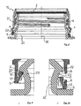
- FIGS. 8 to 10 “Yet another embodiment of the present invention is shown which in all essentials is identical to the embodiments already described, but here shown in section on a bottle neck 20.
- the bottle neck 20 has an external thread 21, onto which the cap 10 is screwed with its internal thread 4.
- the bottleneck has a locking ring 22 below the thread, the outer diameter is again greater than the outer diameter of the thread 21 and the underside, as can be seen in particular in the enlarged cutouts according to the FIGS. 9 and 10 recognizes, substantially flat and perpendicular to the common axis 30 of the bottle neck 20 and the screw cap 10 extends.
- the guarantee strip 5 is still connected via intact elements 7 connected to the lower portion 3 'of the cap skirt, wherein the flex band 6 is completely below the locking ring 22, so that its flat top 17 can come into contact with the flat bottom 24 of the retaining ring when the closure is moved upwards by unscrewing.
- the inwardly projecting projection of the flex band 6 does not overlap with the conical wall portion 23 of the bottle neck 20.
- the apparent overlap is only achieved in the figure in that the cutting plane of the screw cap 10 is slightly offset towards the back through the neck of the bottle.
- the FIGS. 9 and 10 each show enlarged sections of the lower left and right edge of the FIG. 8 , On the right side of the FIG.
- the guarantee strip 5 is shown separated from the lower portion 3 'of the cap skirt 3, ie the easily rupturable fasteners 7 are interrupted or destroyed.
- the flexible band 6 bears against the outside of the conical wall section 23 of the bottle neck under radial tension
- the guarantee strip 5 completely slides downwards until its lower edge rests on an extension of the bottle neck 20, as can be seen in FIG. 10 clearly recognizes.
- the remaining details of the flex band, especially with regard to the changing slightly stretchable and less easily stretched portions are consistent with the embodiments already described, wherein only the shape of the radially inwardly projecting nose-like projections due to an inner Kantenabrundung slightly different from the previously discussed embodiments.
Landscapes
- Engineering & Computer Science (AREA)
- Mechanical Engineering (AREA)
- Closures For Containers (AREA)
Description
Die vorliegende Erfindung betrifft einen Schraubverschluss, bestehend aus einer Schraubkappe und einem Garantieband, wobei die Schraubkappe eine Kopfplatte mit einem zylindrischen Kappenmantel aufweist, der mit einem Innengewinde versehen ist, und wobei das Garantieband ein Flexband aufweist und über ein oder mehrere leicht reißbare Elemente mit dem unteren Rand des Kappenmantels verbunden ist, wobei das Flexband als kontinuierlich umlaufendes Flexband ausgebildet ist, welches über seinen Umfang verteilt mehrere leichter dehnbare Abschnitte sowie dazwischen relativ weniger leicht dehnbare Abschnitte aufweist, und wobei die leichter dehnbaren Abschnitte einen geringeren Wandquerschnitt, insbesondere im umgeklappten Zustand eine geringere in radialer Richtung gemessene Wandstärke aufweisen als die weniger leicht dehnbaren Abschnitte, wobei die Abschnitte mit dem größeren Wandquerschnitt einen sich nach oben erweiternden, keilförmigen Querschnitt haben, wobei der obere Rand des umgeklappten Flexbandes die am weitesten radial nach innen ragenden Vorsprünge umfasst.The present invention relates to a screw cap, consisting of a screw cap and a guarantee strip, wherein the screw cap has a top plate with a cylindrical cap coat, which is provided with an internal thread, and wherein the guarantee strip has a flex band and one or more easily tearable elements with the is connected to the lower edge of the cap skirt, wherein the flex band is formed as a continuous circumferential Flexband, which has distributed over its circumference several easily stretchable sections and relatively less easily stretchable sections between them, and wherein the more easily expandable sections a smaller wall cross-section, especially in the folded state have smaller measured in the radial direction wall thickness than the less easily stretchable sections, wherein the sections with the larger wall cross section have an upwardly widening, wedge-shaped cross section, wherein the upper edge of the umg folded Flexbandes includes the most radially inwardly projecting protrusions.
Derartige Schraubverschlüsse sind, insbesondere für Behältermündungen oder Verschlussunterteile, deren Durchmesser bei 38 mm oder darunter liegt, in Gebrauch.Such screw caps are, in particular for container mouths or closure bottoms, the diameter of which is 38 mm or less in use.
Aus der
Als "Flexband" wird in der vorliegenden Patentanmeldung der umklappbare Teil eines Garantiebandes bezeichnet, der sich zwar bei und unmittelbar nach der Herstellung annähernd in axialer Verlängerung des Kappenmantels und eines äußeren Garantiebandabschnittes erstreckt, der jedoch nach innen und oben (in Richtung der Kopfplatte) umklappbar ist und dessen freies Ende eine im umgeklappten Zustand nach oben weisende Anlagefläche aufweist, die sich beim Lösen einer Schraubkappe an die Unterseite eines Sicherungsringes anlegt, wenn der sich an einem Verschlussunterteil oder einem entsprechenden Behälterhals unterhalb des zu der Schraubkappe passenden Außengewindes befindet.As a "flex band" is referred to in the present patent application, the hinged part of a guarantee strip, which extends during and immediately after production approximately in the axial extension of the cap skirt and an outer guarantee band section, but which folds inwards and upwards (in the direction of the top plate) is and its free end a in the folded state upwardly facing bearing surface which applies when loosening a screw cap to the underside of a retaining ring when it is located on a closure bottom or a corresponding container neck below the mating to the screw external thread.
Derartige Flexbänder sind in vielfältigen Ausgestaltungen bekannt, insbesondere auch in Form getrennter, einzeln umklappbarer Segmente und mit Unterbrechungen, welche das Aufbringen eines unversehrten Verschlusses und insbesondere des unversehrten Garantiebandes auf dem Behälterhals oder einem entsprechenden Unterteil erleichtern sollen. Für eine ordnungsgemäße Funktion muss der freie Innendurchmesser des Flexbandes, der sich im umgeklappten Zustand einstellt, deutlich kleiner sein als der Außendurchmesser des Sicherungsringes an dem Behälterhals oder Verschlussunterteil, welchen das Flexband hintergreifen soll. Damit das Flexband, welches über eine als Scharnier wirkende Schwachstelle mit dem äußeren Abschnitt des Garantiebandes verbunden ist, sich beim Einwirken einer axialen Kraft auf das freie Ende, konkret beim in Eingrifftreten mit der Unterseite des Sicherungsringes während des Abschraubens der Schraubkappe nicht einfach nach unten entrollt und in eine Position zurückklappt, in der es im Wesentlichen eine axiale Verlängerung des äußeren Abschnittes des Garantiebandes bildet und auf diese Weise über den Sicherungsring hinweg gleiten kann, muss es zum einen in sich genügend Steifigkeit aufweisen, und es muss sich im umgeklappten Zustand unter einem relativ spitzen Winkel (bezogen auf die zylindrische Innenwand des äußeren Garantiebandabschnittes) nach oben erstrecken. Bei entsprechend spitzem Winkel wirkt eine axiale Kraft überwiegend in Längsrichtung der mehr oder weniger zylindrischen oder leicht konischen Wand des Flexbandes und übt über den Scharnierabschnitt eine entsprechende axiale Zugkraft auf den äußeren Abschnitt des Garantiebandes aus, die zum Zerreißen der leicht zerreißbaren Verbindung bzw. Verbindungen zwischen Garantieband und dem unteren Rand der Schraubkappe führt.Such flexbands are known in a variety of configurations, especially in the form of separate, individually foldable segments and with interruptions, which should facilitate the application of an intact closure and in particular the intact guarantee band on the container neck or a corresponding lower part. For proper operation, the free inner diameter of the flex band, which sets in the folded state, must be significantly smaller than the outer diameter of the retaining ring on the container neck or closure bottom, which is to engage behind the Flexband. So that the flex band, which is connected via a weak point acting as a hinge with the outer portion of the guarantee band, unrolls when acting on an axial force on the free end, specifically when engaging with the underside of the locking ring during unscrewing the screw simply down and folding back into a position in which it essentially forms an axial extension of the outer portion of the guarantee strip and in this way can slide over the retaining ring, it must on the one hand enough rigidity in itself, and it must be in the folded state under a extending relatively acute angle (relative to the cylindrical inner wall of the outer guarantee strap portion) upwards. At a corresponding acute angle, an axial force acts predominantly in the longitudinal direction of the more or less cylindrical or slightly conical wall of the flex belt and exerts on the hinge portion a corresponding axial tensile force on the outer portion of the guarantee band, which is sufficient to rupture the easily breakable connection or connections between The guarantee strip and the lower edge of the screw cap leads.
Wird dieser Winkel zwischen Flexband und der Achse der Schraubkappe bzw. dem (zu der Achse im Wesentlichen parallelen) äußeren Garantiebandabschnitt jedoch zu groß, so wirkt eine erhebliche Komponente einer axial gerichteten Kraft auch senkrecht zu der Wand des Flexbandes und nicht in seine Längsrichtung, was das erwähnte "Entrollen" bzw. Umklappen des Flexbandes bewirkt, ohne dass die leicht reißbaren Verbindungen zwischen Garantieband und Schraubkappe abreißen.However, if this angle between the flex band and the axis of the screw cap or the (substantially parallel to the axis) outer guarantee band section is too large, a significant component of an axially directed force also acts perpendicular to the wall of the flex band and not in its longitudinal direction, which causes the mentioned "unrolling" or folding the Flexbandes, without tearing off the easily tearable connections between the guarantee strip and screw cap.
Es kommt also wesentlich darauf an, dass eine Schraubkappe und deren Flexband in ihren Maßen hinreichend genau auf einen Flaschenhals bzw. ein entsprechendes Verschlussunterteil abgestimmt sind, so dass das Flexband nach dem Aufbringen der Schraubkappe auf einen Behälterhals oder ein Verschlussunterteil, wenn es unterhalb des Sicherungsringes am Außenumfang des Behälterhalses anliegt, eine entsprechende Position einnimmt, in welcher die Wand des Flexbandes mit der Wand des äußeren Abschnittes des Garantiebandes bzw. mit der Achse des Verschlusses einen hinreichend spitzen Winkel einschließt, der nach Möglichkeit 30° nicht überschreiten sollte.It is therefore essential that a screw cap and its flex band are sufficiently matched in their dimensions to a bottleneck or a corresponding closure bottom, so that the Flexband after applying the screw cap on a container neck or a closure base, if it is below the retaining ring rests against the outer circumference of the container neck, assumes a corresponding position in which the wall of the flex band with the wall of the outer portion of the guarantee strip or with the axis of the closure includes a sufficiently acute angle, which should not exceed 30 ° if possible.
Grundsätzlich ist es zwar möglich, entsprechende Schraubverschlüsse und deren Flexbänder mit relativ kleinen Toleranzen herzustellen, die sich im Bereich von ± 0,1 mm bewegen, jedoch gibt es einige Behältertypen und Verschlusstypen, bei denen das entsprechende Gegenstück, nämlich ein Behälterhals oder aber auch ein Verschlussunterteil, nicht ebenfalls mit einer entsprechenden Genauigkeit hergestellt worden ist bzw. hergestellt werden kann.In principle, it is possible to produce corresponding screw caps and their flexible bands with relatively small tolerances, which are in the range of ± 0.1 mm, but there are some types of containers and types of closure, in which the corresponding counterpart, namely a container neck or even a Closure lower part, not also with a corresponding accuracy has been made or can be produced.
Dies gilt insbesondere für Behälter aus extrusionsgeblasenem Kunststoff (HDPE, PET etc.), bei denen der Flaschenhals zusammen mit dem Blasvorgang und teilweise auch durch den Blasvorgang geformt wird. Im Gegensatz zu durch Spritzguss hergestellten Behälterhälsen wird in diesem Fall zumindest der innere Teil der "Form" durch unter entsprechendem Druck stehendes Gas (im Allgemeinen Luft) ersetzt.This applies in particular to containers made of extrusion-blown plastic (HDPE, PET, etc.) in which the neck of the bottle is formed together with the blowing process and in part also by the blowing process. In contrast to injection-molded container necks, in this case at least the inner part of the "mold" is replaced by pressurized gas (generally air).
Die durch Blasformen hergestellten Behälterhälse haben daher oft wesentlich größere Ungenauigkeiten und typische Toleranzen von bis zu ± 0,3% oder mehr. Dies wirkt sich insbesondere bei großen Durchmessern von 35 mm und darüber nachteilig aus, weil in einem solchen Fall Schraubkappen mit entsprechenden Flexbändern, die auf das Sollmaß derartiger Behälterhälse oder auch Verschlussunterteile abgestellt sind, nicht mehr exakt zu den so hergestellten Behälterhälsen passen. Beispielsweise kann es geschehen, dass bei einem durch Blasformen hergestellten Behälterhals mit einem Nenndurchmesser von 63 mm der Außendurchmesser des Behälterhalses unterhalb des Sicherungsringes im Falle einer Toleranzabweichung von - 0,3% um bis zu 0,2 mm kleiner ist als das Sollmaß. Wenn dann umgekehrt der Durchmesser des Garantiebandes der zugehörigen Verschlusskappe eine Toleranzabweichung von +0,1 mm hat, so beträgt die effektive Anweichung des Durchmesser des Garantiebandes im Bereich des Scharnierabschnittes sowie des Außendurchmessers des Behälterhalses unterhalb des Sicherungsringes 0,3 mm gegenüber dem entsprechenden Sollmaß. Mit anderen Worten, das obere Ende des Flexbandes, welches den kleinsten Durchmesser des Flexbandes bildet und mit seinem inneren oberen Rand an der Außenfläche des Flaschenhalses anliegt, kann um 0,15 mm weiter radial einwärts ausweichen (und dabei um den Scharnierbereich verkippen) als bei Einhaltung der Sollmaße.The blow-molded container necks therefore often have significantly greater inaccuracies and typical tolerances of up to ± 0.3% or more. This is particularly disadvantageous for large diameters of 35 mm and above, because in such a case screw caps with corresponding flex bands, which are placed on the nominal size of such container necks or closure bottoms, no longer fit exactly to the container necks thus produced. For example, it may happen that in a produced by blow molding container neck with a nominal diameter of 63 mm, the outer diameter of the container neck below the retaining ring in the case of a tolerance deviation of - 0.3% by up to 0.2 mm smaller than the nominal size. If, conversely, the diameter of the guarantee strip of the associated closure cap has a tolerance deviation of +0.1 mm, then the effective softening of the diameter of the guarantee strip in the region of the hinge section and the outside diameter of the container neck below the retaining ring is 0.3 mm compared to the corresponding nominal dimension. In other words, the upper end of the flex band, which is the smallest diameter of the flex band and rests with its inner upper edge on the outer surface of the bottle neck, can dodge further inwardly by 0.15 mm (tilting about the hinge portion) than at Compliance with the nominal dimensions.
Wenn auch die axiale Länge des Flexbandes von dem Scharnierbereich bis zum freien Ende in der Größenordnung von nur wenigen mm liegt und z. B. 3 mm beträgt, bedeutet eine weitere Verkippung des oberen Abschnittes des Flexbandes um 0,15 mm nach innen, da auch bei Einhaltung der Sollmaße die Wand des Flexbandes typischerweise bereits um bis zu 20° gegenüber dem äußeren Abschnitt des Garantiebandes verkippt ist, bei genauer Berücksichtigung der konkreten Geometrien eine Vergrößerung des Kippwinkels (zwischen Flexband und Achse) um bis zu 5°, so dass beim Ausüben einer axialen Kraft auf das freie Ende des Flexbandes diese Kraft zu einem erheblichen Teil in eine senkrecht zur Wand des Flexbandes wirkende Kraftkomponente umgesetzt wird, die als Biegekraft bezüglich des Schamierabschnittes wirkt und zu einem sogenannten "Entrollen", d.h. Umklappen des Flexbandes um den Scharnierabschnitt, führen kann.Although the axial length of the flex band from the hinge area to the free end of the order of only a few mm and z. B. 3 mm, means a further tilting of the upper portion of the flex band to 0.15 mm inward, since even with compliance with the nominal dimensions of the wall of the flex belt is typically already tilted by up to 20 ° relative to the outer portion of the guarantee strip at more precise consideration of the concrete geometries an increase of the tilt angle (between flex band and axis) by up to 5 °, so that when exerting an axial force on the free end of the flex band, this force implemented to a considerable extent in a force acting perpendicular to the wall of the flex band force component is acting as a bending force with respect to the hinge section and a so-called "unrolling", ie Folding the Flexbandes around the hinge section, can lead.
Diese Gefahr wird noch dadurch vergrößert, dass unvermeidlich manche Abschnitte des Garantiebandes zuerst abreißen und dann unter der Wirkung der Schwerkraft am Behälterhals herabrutschen, der sich typischerweise unterhalb des Sicherungsringes und weg von dem Sicherungs-Diese Gefahr wird noch dadurch vergrößert, dass unvermeidlich manche Abschnitte des Garantiebandes zuerst abreißen und dann unter der Wirkung der Schwerkraft am Behälterhals herabrutschen, der sich typischerweise unterhalb des Sicherungsringes und weg von dem Sicherungsring verjüngt, so dass das Flexband noch mehr Spiel erhält und auf der gegenüberliegenden Seite noch leichter entrollt bzw. umgeklappt werden kann, ohne dass das Garantieband in diesem Bereich von dem Kappenmantel abreißt. Im Ergebnis führen also solche Toleranzabweichungen dazu, dass entweder das Flexband zurückgeklappt wird und sich überhaupt nicht von dem Kappenmantel ablöst, oder aber nur teilweise von der Kappe ablöst und zumindest in einem kleineren Bereich noch an dem Kappenmantel hängt. Der Verbraucher wird dann ein solches lose herabhängendes und bei der Wiederverwendung der Schraubkappe störendes Garantieband in der Regel abreißen, oder aber das Garantieband kann auch von selbst bei der weiteren Handhabung des Verschlusses abreißen, was wiederum die Gefahr in sich birgt, dass es in den Behälter fällt oder in einen anderen Behälter fällt, in welchen die in dem Behälter enthaltene Flüssigkeit ausgegossen werden soll. Beispielsweise könnte die Flüssigkeit bzw. Substanz, die sich in dem mit dem Schraubverschluss versehenen Behälter befindet, in einen Mischer oder eine Anlage zur Portionierung gefüllt werden, wobei ein unabsichtlich in den Mischer fallendes Garantieband zu erheblichen Betriebsstörungen führen kann.This danger is exacerbated by the inevitable breaking off of some portions of the tamper-evident band and then sliding down the container neck under the action of gravity, typically below the circlip and away from the circlip Danger is further increased by inevitably tearing off some portions of the tamper-evident band and then sliding down the container neck under the action of gravity, which typically tapers below the circlip and away from the circlip, giving the flexbelt even more clearance and on the opposite side Page even more easily unrolled or can be folded without the guarantee strip tears off in this area of the cap jacket. As a result, such tolerance deviations lead to either the flex band being folded back and not detaching from the cap casing at all, or being only partially detached from the cap and still hanging on the cap casing at least in a smaller area. The consumer will then tear off such a loosely hanging and annoying in the reuse of the screw cap guarantee strip, or the guarantee strip can tear off by itself in the further handling of the closure, which in turn carries the risk that it is in the container falls or falls into another container in which the liquid contained in the container is to be poured out. For example, the liquid or substance that is in the container provided with the screw cap could be filled into a mixer or a portioning system, wherein an unintentionally falling into the mixer guarantee band can lead to significant malfunction.
Außerdem würde durch ein Garantieband, das sich durch Entrollen des Flexbandes von einem Behälterhals lösen lässt, ohne dass das Garantieband von der Schraubkappe abreißt, die Gefahr von Manipulationen des Behälterinhaltes vergrößert, da dann ein solcher Zustand auch absichtlich herbeigeführt werden könnte, um den Behälterinhalt auszutauschen und/oder zu verändern.In addition, a guarantee strip, which can be solved by unrolling the Flexbandes of a container neck without the guarantee strip tears from the screw cap, the risk of manipulation of the container contents increased, since then such a state could also be deliberately brought about to replace the container contents and / or change.
Als nächstliegender Stand der Technik wird die
Durch diese Anordnung können allerdings jeweils nur die radial inneren Eckbereiche der weniger leicht dehnbaren Abschnitte einen Sicherungsring am Behälterhals hintergreifen. Die leichter dehnbaren Abschnitte bzw. deren jeweilige Verbindung mit den weniger leicht dehnbaren Abschnitten wirkt nun beim hinwegbewegen des Flexbandes über einen Sicherungsring, wie es beim Aufbringen des Verschlusses auf einen Behälterhals erforderlich ist, als eine Art Schanier, sodass die Zickzack-Anordnungder leichter und weniger leicht dehnbaren Abschnitt etwas gestreckt wird und dadurch einen durch die radial inneren Ecken der wenig leicht dehnbaren Abschnitte definierten Innenradius annehmen kann und sich somit relativ leicht über einen Sicherungsring hinwegschieben lässt. Die Vergrößerung des effektiven Innendurchmessers des Flexbandes erfolgt also durch eine Erstreckung der Zickzack-Anordnung der leichter und der weniger leicht dehnbaren Abschnitt und nicht in erster Linie durch eine stärkere Dehnung der leichter dehnbaren Abschnitte.By this arrangement, however, only the radially inner corner regions of the less easily stretchable sections can engage behind a retaining ring on the container neck. The more easily stretchable portions, or their respective connection to the less easily stretched portions, now act as a hinge in moving the flex band over a circlip, as required in applying the closure to a container neck, so that the zigzag arrangement is lighter and less slightly stretchable portion is slightly stretched and thereby can assume an inner radius defined by the radially inner corners of the slightly stretchy sections and thus relatively easy to push over a retaining ring. The enlargement of the effective inner diameter of the flex band thus takes place by an extension of the zigzag arrangement of the lighter and the less easily stretchable section and not primarily by a greater elongation of the more easily stretchable sections.
Diese Anordnung hat vor allem den Nachteil, dass nicht richtig sichergestellt ist, dass die weniger leicht dehnbaren Abschnitte des Flexbandes, die die eigentliche Rückhaltefunktion bewirken. nicht über ihre volle Länge hinweg an den entsprechenden Sicherungsring hintergreifen, da sie durch die Verbindung mit den benachbarten weniger leicht dehnbaren Abschnitten an einem in die jeweils in einem größeren radialen Abstand gehalten werden.This arrangement has the particular disadvantage that it is not properly ensured that the less easily stretchable portions of the flex band, which cause the actual retention function. do not engage over the full length of the corresponding locking ring, since they are held by the connection with the adjacent less easily stretchable sections at a in each case at a greater radial distance.
Gegenüber diesem Stand der Technik liegt der vorliegenden Erfindung die Aufgabe zugrunde einen Schraubverschluss mit Flexband zu schaffen, der auch bei größeren Toleranzabweichungen zwischen Verschluss und Behälterhals noch ein sicheres Abreißen des Garantiebandes gewährleistet und auch bei größeren Toleranzabweichungen Funktionssicherheit bietet und zum Anderen auch ein Hintergreifen eines Behältersicherungsringes im Wesentlichen über die gesamte Länge der weniger leicht dehnbaren Abschnitte hinweg ermöglicht. Dabei soll insbesondere die Dehnbarkeit der leichter dehnbaren abschnitte für das Aufbringen des Verschlusses auf einen Behältershals ausgenutzt werden.Compared to this prior art, the present invention has the object to provide a screw with Flexband, which ensures even with larger tolerance deviations between closure and container neck still a safe tearing off the tamperproof and also provides greater tolerance deviations reliability and on the other hand, a grip behind a container locking ring essentially over the entire length of the less easily stretchable sections. In particular, the extensibility of the easily stretchable sections should be exploited for applying the closure to a container neck.
Diese Aufgabe wird durch die Merkmale des Anspruchs 1 gelöst. Zuzüglich zu den oben bereits erwähnten Merkmalen, die die vorliegende Erfindung mit dem Gegenstand der
Zweckmäßigerweise definiert der obere innerer Rand der weniger stark dehnbaren Abschnitte im umgeklappten Zustand des Flexbandes den kleinsten Innendurchmesser des Flexbandes, so dass dieser obere innere Rand im Gebrauch unterhalb des Sicherungsringes an dem Flaschenhals anliegt.Conveniently, the upper inner edge of the less extensible portions in the folded state of the flex band defines the smallest inner diameter of the flex band, so that this upper inner edge rests against the bottleneck in use below the locking ring.
Insbesondere können die weniger leicht dehnbaren Abschnitte radial einwärts ragende Vorsprünge aufweisen, die den kleinsten Innendurchmesser des umgeklappten Flexbandes definieren.In particular, the less easily stretchable portions may have radially inwardly projecting projections defining the smallest inner diameter of the folded-over flex band.
Die radial einwärts ragenden Vorsprünge sind am oberen freien Ende des Flexbandes vorgesehen. Außerdem sind im Querschnitt dreieckige bzw. nasenförmige Vorsprünge bevorzugt, die den oberen Endabschnitt der weniger leicht dehnbaren Abschnitte bilden und ihre maximale radiale Ausdehnung am freien Ende des Flexbandes haben. Die Oberseite der Vorsprünge bildet dann einen Teil der mit der Unterseite eines Sicherungsringes in Eingriff tretenden Fläche. Es versteht sich jedoch, dass die Vorsprünge auch weitgehend beliebige, andere Querschnittsformen haben können, zum Beispiel rechteckig oder mit komplexeren, mehreckigen oder auch abgerundeten Umrissen ausgestaltet sein können.The radially inwardly projecting projections are provided at the upper free end of the flex band. In addition, in the cross-section triangular or nose-shaped projections are preferred, which form the upper end portion of the less easily stretchable portions and have their maximum radial extent at the free end of the flex band. The top of the protrusions then forms part of the surface engaging the underside of a locking ring. It is understood, however, that the projections can also have largely any, other cross-sectional shapes, for example, rectangular or with more complex, polygonal or rounded outlines can be configured.
Die leichter dehnbaren Abschnitte werden durch Abschnitte mit einem geringeren Wandquerschnitt gebildet, insbesondere durch Abschnitte, die im umgeklappten Zustand eine geringere, in radialer Richtung gemessene Wandstärke aufweisen als die übrigen, weniger leicht dehnbaren Abschnitte. Diese weniger leicht dehnbaren Abschnitte bzw. die Abschnitte mit dem größeren Wandquerschnitt haben einen sich nach oben erweiternden Querschnitt, wobei der obere Rand des umgeklappten Flexbandes die am weitesten radial nach innen ragenden Vorsprünge umfasst. Die hier angesprochenen Querschnitte sind im Übrigen immer durch Querschnittsebenen definiert, die durch die Achse der Schraubkappe und einen von der Achse ausgehenden Radius aufgespannt werden.The more easily expandable sections are formed by sections having a smaller wall cross-section, in particular by sections which, in the folded-over state, have a smaller wall thickness measured in the radial direction than the remaining, less easily stretched sections. These less easily stretchable sections or the sections with the larger wall cross-section have an upwardly extending cross-section, wherein the upper edge of the folded-over Flexband includes the most radially inwardly projecting protrusions. Incidentally, the cross-sections mentioned here are always defined by cross-sectional planes which are defined by the axis of the screw cap and a radius extending from the axis.
Die Vorsprünge bewirken also unvermeidlich auch eine effektive Vergrößerung des Querschnitts des Flexbandes, was wiederum zu der weniger leichten Dehnbarkeit dieser Abschnitte beiträgt.The projections thus inevitably also cause an effective enlargement of the cross section of the flex band, which in turn contributes to the less easy extensibility of these sections.
Dabei hat es sich als zweckmäßig erwiesen, wenn zwischen 5 und 15 leichter dehnbare Abschnitte alternierend mit jeweils dazwischen liegenden, weniger leicht dehnbaren Abschnitten über den Umfang des Flexbandes verteilt vorgesehen sind.It has proved to be useful if between 5 and 15 easily stretchable sections are provided alternately with each intervening, less easily stretchable sections distributed over the circumference of the flex band.
Der Vorteil eines Flexbandes, welches über seinen Umfang verteilt mehrere leichter dehnbare Abschnitte sowie dazwischen weniger leicht dehnbare Abschnitte aufweist, die im umgeklappten Zustand auch noch radial einwärts ragende Vorsprünge aufweisen, liegt darin, dass ein solches Flexband noch besser für das Auffangen größerer Toleranzabweichungen geeignet ist. Insbesondere kann ein solches Flexband von vornherein mit einem kleineren Sollmaß seines Innendurchmessers konzipiert und hergestellt werden, wobei dieser Innendurchmesser des Flexbandes der freie Innendurchmesser des Flexbandes ist, der sich im nach oben umgeklappten Zustand des Flexbandes einstellt. Im vorliegenden Fall wird dieser Innendurchmesser durch die jeweils einwärts ragenden Vorsprünge der weniger leicht dehnbaren Abschnitte definiert. Wenn diese Vorsprünge einen relativ kleinen Radius definieren, steht die eigentliche Wand des Flexbandes, die durch die Verbindung von dem Scharnierabschnitt durch das Zentrum des von dort ausgehenden Wandabschnittes definiert wird, noch immer relativ steil und unter einem sehr spitzen Winkel oder nahezu parallel zu der Außenwand des Garantiebandes bzw. zur Achse des Verschlusses.The advantage of a Flexbandes distributed over its circumference several easily stretchable sections and between less easily stretchable sections, which also have radially inwardly projecting projections in the folded state, is that such a Flexband is even better suited for capturing larger tolerance deviations , In particular, such a flex band can be designed and manufactured from the outset with a smaller nominal dimension of its inside diameter, wherein this inside diameter of the flex band is the free inside diameter of the flex band, which adjusts itself in the folded-up state of the flex band. In the present case, this inner diameter is defined by the respective inwardly projecting projections of the less easily stretched sections. When these protrusions define a relatively small radius, the actual wall of the flex band, which is through the connection from the hinge portion through the center of the latter, stands outgoing wall portion is defined, still relatively steep and at a very acute angle or nearly parallel to the outer wall of the guarantee strip or to the axis of the closure.
Dabei sorgen die leichter dehnbaren Abschnitte dafür, dass trotz dieses relativ geringen Innendurchmessers des Flexbandes selbiges dennoch ohne zu Zerreißen über den Sicherungsring hinweg bewegt werden kann, der einen deutlich größeren Außendurchmesser hat.The more easily stretched sections ensure that, despite this relatively small inner diameter of the flex band, the same can nevertheless be moved without tearing over the securing ring, which has a significantly larger outside diameter.
Die radial am weitesten einwärts ragenden Vorsprünge sind dabei so gestaltet, dass sie vergleichweise leicht verformbar sind und so das Hinwegschieben des Flexbandes über den Sicherungsring zusätzlich erleichtern.The radially inwardly projecting protrusions are designed so that they are comparatively easily deformable and thus facilitate the push-away of the Flexbandes on the retaining ring in addition.
In einer Ausführeungsform definiert die im umgeklappten Zustand radial außen liegende Wand des Flexbandes, nachdem die Schraubkappe auf einen Behälterschluss mit Sollmaß aufgesetzt ist, einen in etwa konusförmigen umlaufenden Wandabschnitt mit einem relativ spitzen Konuswinkel, der dem Winkel zwischen der Wand des Flexbandes und der Axialrichtung entspricht. Die im umgeklappten Zustand radial außen liegende Wand des Flexbandes kann zusätzlich zu dieser konusförmig umlaufenden Grundform am oberen Ende des Flexbandes noch einen radial nach außen leicht verdickten Wulst bzw. Wulstrand aufweisen. Passend hierzu hat in der bevorzugten Ausführungsform der Erfindung das Garantieband auf seiner Innenfläche eine entsprechende, umlaufende Aussparung, um diesen Wulstrand aufzunehmen. Wenn der Wulstrand vollständig in die Aussparung hineingedrückt ist, erstreckt sich die Wand des Flexbandes nahezu parallel zu dem äußeren Abschnitt des Garantiebandes bzw. parallel zur axialen Richtung. Diese Position nimmt das Flexband vor allem dann ein, wenn es über den Sicherungsring hinweg bewegt wird und dabei maximal aufgeweitet wird.In one embodiment, the radially outboard wall of the flex band in the folded state defines, after the screw cap is seated to a desired pitch, an approximately tapered circumferential wall portion having a relatively acute cone angle corresponding to the angle between the wall of the flex band and the axial direction , In the folded-over state, the radially outer wall of the flex band can additionally have a radially outwardly slightly thickened bead or bead edge at the upper end of the flex band in addition to this cone-shaped circumferential basic shape. Fits thereto, in the preferred embodiment of the invention, the guarantee strip on its inner surface has a corresponding circumferential recess to accommodate this bead. When the bead edge is fully pressed into the recess, the wall of the flex band extends nearly parallel to the outer portion of the guarantee band or parallel to the axial direction. This position is particularly important for the flex band when it is moved over the circlip and is maximally expanded.
Der spitze Winkel zwischen Flexband und Achse des Verschlusses wird, soweit gemäß einer bevorzugten Ausführungsform die Außenwand des Flexbandes im umgeklappten Zustand eine Konuswand definiert bzw. eine Konuswand als Einhüllende aufweist, zweckmäßigerweise durch den zur Achse hin gemessenen Konuswinkel definiert. Für die im Wesentlichen entlang der Flexbandwand vom freien Ende zum Scharnierabschnitt gerichtete Kraftaufnahme beim in Eingriff Treten der Oberseite des Flexbandes mit der Unterseite des Sicherungsringes kommt es wesentlich auf die steile Ausrichtung der äußeren Wandabschnitte des Flexbandes an, um eine senkrecht zur Wand des Flexbandes gerichtete Biegekraft zu vermeiden und die Kraft überwiegend als axiale Zugkraft auf den äußeren Garantiebandabschnitt zu übertragen. Ein kleiner Winkel zwischen der konischen Außenwand des Flexbandes und der Achse der Schraubkappe ist insofern ein gutes Maß und Indiz für die Funktionsfähigkeit des Garantiebandes.The acute angle between the flex band and the axis of the closure, as far as according to a preferred embodiment, the outer wall of the flex band defined in the folded state, a cone wall or a cone wall as an envelope, expediently defined by the conical angle measured towards the axis. For the substantially along the flex band wall from the free end to the hinge portion directed force when engaging the top of the flex band with the underside of the retaining ring is essential to the steep alignment of the outer wall portions of the flex band to a directed perpendicular to the wall of the flex belt bending force to avoid and to transmit the force predominantly as axial tensile force on the outer guarantee band section. A small angle between the conical outer wall of the flex strip and the axis of the screw cap is a good measure and an indication of the functioning of the guarantee strip.
In einer bevorzugten Ausführungsform der Erfindung nehmen die dickwandigen Abschnitte mit den radial einwärts ragenden Vorsprüngen in Umfangsrichtung jeweils das Zwei- bis Zehnfache der entsprechenden Umfangsabschnitte eines dehnbaren bzw. dünnwandigen Abschnittes ein.In a preferred embodiment of the invention, the thick-walled portions with the radially inwardly projecting projections in the circumferential direction occupy respectively two to ten times the corresponding peripheral portions of a stretchable or thin-walled portion.
In einer konkreten Variante eines Verschlusses mit 65 mm Nenndurchmesser sind insgesamt neun leichter dehnbare Abschnitte abwechselnd mit weniger dehnbaren Abschnitten vorgesehen, wobei die leichter dehnbaren Abschnitte jeweils etwa ein Fünftel derjenigen Umfangsabschnitte in Anspruch nehmen, die jeweils von den weniger leicht dehnbaren Abschnitten in Anspruch genommen werden.In a specific variant of a closure with a nominal diameter of 65 mm, a total of nine more easily expandable sections are provided alternately with less extensible sections, the more easily expandable sections each occupying about one fifth of the peripheral sections each occupied by the less easily stretched sections ,
Auch die weniger leicht dehnbaren Abschnitte können in sich noch weiter strukturiert sein, indem beispielsweise die jeweils in Umfangsrichtung liegenden Endabschnitte des oberen Randes der weniger leicht dehnbaren Umfangsabschnitte jeweils noch etwas ausgeprägtere und weiter radial einwärts ragende nasenförmige Vorsprünge haben als die dazwischen liegenden Bereiche. Auch diese Endabschnitte können wiederum etwa ein Zehntel bis ein Viertel des entsprechenden Umfangsabschnittes ausmachen.The less easily stretchable sections can also be further structured in that, for example, each of the circumferentially lying end portions of the upper edge of the less easily stretchable peripheral portions each have something more pronounced and further radially inwardly projecting nose-shaped projections than the intermediate areas. These end sections can again make up about one-tenth to one-fourth of the corresponding peripheral section.
Wie bereits erwähnt, haben die näherungsweise nasenförmigen Vorsprünge eine in etwa dreieckige Grundform, und setzen an der Innenseite eines bereits keilförmigen Wandquerschnittes der dickwandigeren Abschnitte an. Wenn man bereits das Keilprofil dieser Abschnitte im Vergleich zum Profil der dünnwandigen, leichter dehnbaren Abschnitten als Vorsprung im Sinne des Anspruchs 1 versteht, kann man das Querschnittsprofil der weniger leicht dehnbaren Abschnitte in einer bevorzugten Ausführungsform auch dahingehend beschreiben dass die dreieckigen Vorsprünge eine nach innen, d.h. in das Dreiecksprofil hinein, abgeknickte Hypotenuse aufweisen. Dies führt dazu, dass der obere Endabschnitt der radial einwärts ragenden Vorsprünge einen noch etwas spitzwinkligeren Querschnitt erhält, d.h. der Winkel zwischen der Oberseite des Flexbandes, die die Oberseite der nasenförmigen Vorsprünge umfasst, und der Innenfläche der nasenförmigen Vorsprünge wird noch etwas kleiner als ohne eine entsprechend einwärts abgeknickte Hypotenuse.As already mentioned, the approximately nose-shaped projections have an approximately triangular basic shape, and set against the inside of an already wedge-shaped wall cross-section of the thicker-walled sections. If one already understands the spline of these sections as compared to the profile of the thin-walled, more easily stretchable sections as a projection in the sense of claim 1, one can also describe the cross-sectional profile of the less easily stretchable sections in a preferred embodiment in that the triangular projections inwardly, ie have in the triangle profile, kinked hypotenuse. This results in the upper end portion of the radially inwardly projecting protrusions being given a somewhat more acute cross section, i. the angle between the top of the flex band, which comprises the top of the nose-shaped projections, and the inside surface of the nose-shaped protrusions is still somewhat smaller than without a corresponding inwardly kinked hypotenuse.
Vorzugsweise ist die Erfindung vorgesehen für Schraubkappen, deren Nenndurchmesser mindestens 35 mm beträgt, wobei die Vorteile noch stärker zur Geltung kommen, wenn der Nenndurchmesser der Schraubkappe größer wird, also insbesondere mindestens 50 mm beträgt.Preferably, the invention is provided for screw caps whose nominal diameter is at least 35 mm, the advantages are even more pronounced when the nominal diameter of the screw cap is larger, that is in particular at least 50 mm.
Die Erfindung ist außerdem gerichtet auf die Kombination eines Behälters und einer auf den Behälterhals aufschraubbaren Schraubkappe, mit einem Behälterhals und einem daran angeformten, den Behälterhals umgebenden und flanschartig nach außen ragenden Sicherungsring. Hinsichtlich dieser Kombination wird die der Erfindung zugrunde liegende Aufgabe dadurch gelöst, dass die Schraubkappe die Merkmale mindestens eines der Ansprüche 1 bis 11 aufweist.The invention is also directed to the combination of a container and a screw on the container neck screw cap, with a container neck and a molded thereto, the container neck surrounding and flange-like outwardly projecting circlip. Regarding this combination, the object underlying the invention is achieved in that the screw cap has the features of at least one of claims 1 to 11.
Dabei sollte der durch die weniger leicht dehnbaren Abschnitte des gebrauchsfertig umgeklappten Flexbandes definierte Innendurchmesser desselben insbesondere kleiner sein als der Außendurchmesser des Flaschenhalses unmittelbar unterhalb des Sicherungsringes, was bedeutet, dass nach dem Aufbringen des Verschlusses das Flexband durch den Flaschenhals unterhalb des Sicherungsringes aufgeweitet gehalten wird und unter Spannung an dem Flaschenhals anliegt. Weiterhin ist in der bevorzugten Variante einer solchen Kombination vorgesehen, dass sich der Außendurchmesser des Flaschenhalses unterhalb des Sicherungsringes und mit zunehmendem Abstand von diesem Sicherungsring verjüngt. Diese im Wesentlichen konische Verjüngung nach unten bewirkt, dass sich das abgelöste Garantieband wegen der Spannung, mit welcher das Flexband an dieser konischen Fläche anliegt, entlang des Flaschenhalses nach unten bewegt und nicht nach oben verschoben werden kann, um beispielsweise in manipulativer Absicht ein mit der Schraubkappe noch fest verbundenes Garantieband vorzutäuschen.In this case, the defined by the less easily stretchable portions of the ready folded folded Flexbandes inner diameter thereof should be smaller than the outer diameter of the bottle neck immediately below the retaining ring, which means that after applying the closure, the Flexband is kept expanded by the bottle neck below the retaining ring and under tension against the neck of the bottle. Furthermore, it is provided in the preferred variant of such a combination that the outer diameter of the bottle neck tapers below the securing ring and with increasing distance from this securing ring. This substantially conical taper downwards causes the detached guarantee strip to move down the neck of the bottle, due to the tension with which the flex band abuts against this conical surface, and can not be displaced upwardly, for example to intervene in a manipulative manner To pretend screw cap still firmly connected guarantee band.
Weitere Merkmale, Vorteile und Anwendungsmöglichkeiten der vorliegenden Erfindung werden deutlich anhand der folgenden Beschreibung einer bevorzugten Ausführungsform und der dazu gehörigen Figuren. Es zeigen:
-
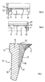
Fig. 1 einen axialen Querschnitt durch einen erfindungsgemäßen Verschluss mit einem gebrauchsfertig umgeklappten Flexband, -
Fig. 2 eine Vergrößerung ausFig. 1 entsprechend dem inFig. 1 eingezeichneten Kreis A, -
Fig. 3 eine Vergrößerung des Ausschnittes B inFig. 1 , -
Fig. 4 eine perspektivische Innenansicht des unteren Abschnittes des Schraubverschlusses mit dem gebrauchsfertig umgeklappten Flexband, -
Fig. 5 eine weitere vergrößerte Darstellung eines Ausschnittes des gebrauchsfertig umgeklappten Flexbandes, teilweise im Schnitt gemäß einer zweiten Ausführungsform, -
Fig. 6 eine weitere teilweise im Schnitt dargestellte perspektivische Ansicht eines Flexbandabschnittes mit einer Schnittlinie durch einen leichter dehnbaren Abschnitt, -
Fig. 7 schematisch den nochmals vergrößerten Querschnitt eines Flexbandes, und -
Figuren 8bis 10
-
Fig. 1 an axial cross section through a closure according to the invention with a ready-folded folded Flexband, -
Fig. 2 an enlargementFig. 1 according to the inFig. 1 drawn circle A, -
Fig. 3 an enlargement of the section B inFig. 1 . -
Fig. 4 an interior perspective view of the lower portion of the screw with the ready-folded folded Flexband, -
Fig. 5 a further enlarged view of a section of the ready-folded folded Flexband, partially in section according to a second embodiment, -
Fig. 6 FIG. 2 a further perspective view, partly in section, of a flexband section with a section line through a section which can be easily stretched, FIG. -
Fig. 7 schematically the again enlarged cross section of a Flexbandes, and -
FIGS. 8 to 10 different views of another embodiment.
Man erkennt in
In den vergrößerten Ausschnitten der
Wie man sieht, hat das Flexband 6 im unteren Bereich und in einem Bereich 9 größerer Wandstärke einen schmalen, keilförmigen Querschnitt. Es versteht sich, dass dieser Querschnitt nicht notwendigerweise schmal keilförmig sein muss, sondern auch unmittelbar oberhalb des Scharnierbereiches konstant sein könnte mit einer gleichmäßigen Wandstärke über die Länge hinweg. Die Länge bzw Längsrichtung kkann definiert werden als die kürzeste Verbindung vom Scharnierbereich 13 zu dem freien Ende mit der oberen Stirnfläche 15 Insbesondere in
Man erkennt in
In der Ausführungsform der
Das Garantieband 5 ist bei 7 über leicht reißbare Elemente bzw. über eine umlaufende, durchgehende Schwachstelle mit dem unteren, erweiterten Rand 3' des Kappenmantels 3 verbunden.The
Wenn die Schraubkappe 1 von einem Behälterhals durch Abschrauben gelöst wird, bewegt sich der gesamte Schraubverschluss 1 zusammen mit dem Garantieband in axialer Richtung nach oben, wobei die Oberseite 15 sich an die Unterseite eines Sicherungsringes (nicht dargestellt) anlegt.When the screw cap 1 is released from a container neck by unscrewing, the entire screw 1 moves together with the guarantee strip in the axial direction upward, the top 15 is applied to the underside of a retaining ring (not shown).
Dabei nimmt das Flexband in etwa die in den
In dieser Position werden die von oben nahezu senkrecht auf die Fläche 15 wirkenden axialen Druckkräfte zwischen Flexband 6 und Sicherungsring im Wesentlichen in Längsrichtung des Flexbandes 6 und durch dessen Wand auf den Scharnierbereich 13 und von dort auf den äußeren Garantiebandabschnitt 12 übertragen, so dass eine entsprechende Zugkraft auf die leicht reißbaren Elemente 7 wirkt, die beim Erhöhen der Kraft durch weiteres Abschrauben der Schraubkappe 1 schließlich zerreißen. Dabei sollten im Verlauf des Abschraubvorganges sämtliche leicht reißbaren Elemente bzw. die Schwächungslinie zwischen Garantieband 5 und Kappenmantel 3 entlang des gesamt Umfanges des Grarantiebandes 5 abreißen, so dass das Garantieband 5 vollständig von der Schraubkappe 1 bzw. dem Kappenmantel 3 getrennt ist und unterhalb des Sicherungsringes am Behälterhals hängen bleibt.In this position, the axial pressure forces between the
Wenn die Außenfläche des Behälterhalses unterhalb des Sicherungsringes sich nach unten konisch verjüngt, sorgt die Spannung im Flexband 6, mit welcher dieses an der Außenseite des Flaschenhalses anliegt, für ein Herabrutschen des Flexbandes an diesen konischen Abschnitt des Behälterhalses, so dass ein deutlich sichtbarer Abstand zwischen dem Garantieband 5 und der gegebenenfalls wieder aufgeschraubten Verschlusskappe verbleibt und anzeigt, dass der Verschluss bereits zumindest einmal geöffnet worden ist. Auf diese Weise erfüllt das Garantieband im intakten, d. h. mit der Schraubkappe 3 fest verbundenen Zustand, seine Funktion als Garantie für die Unversehrtheit des Behälterinhaltes.When the outer surface of the container neck tapers conically downwardly below the circlip, the tension in the
In
Dabei ist jedoch zu betonen, dass die relativen Abmessungen, insbesondere die in dieser Querschnittsdarstellung erkennbaren Wandstärken nicht notwendigerweise mit den tatsächlichen Maßen übereinstimmen müssen, auch wenn sie den tatsächlichen Verhältnissen nahekommmen mögen.However, it should be emphasized that the relative dimensions, in particular the wall thicknesses which can be discerned in this cross-sectional representation, do not necessarily have to correspond to the actual dimensions, even if they may be close to the actual conditions.
Die leichter dehnbaren, eine geringere Wandstärke aufweisenden Abschnitte 8 haben einen Querschnitt, wie er durch die linkseitige Außenwand 16 und die vertikale gestrichelte Linie 17 wiedergegeben wird, wobei sich diese Wandstärke nach unten hin zu dem Scharnierbereich 13 nochmals leicht verjüngt. Die Längsrichtung des Flexbandes ist in diesem Querschnittes im Wesentlichen die Vertikale bzw. die Wand 16, die sich vom Scharnierbereich 13 nach oben zu dem freien Ende des Flexbandes 6 erstreckt, dass durch die Stirnfläche 15 definiert wird.The more easily stretched, smaller
Die Abschnitte 9 mit größerer Wandstärke haben zusätzlich zu dem keilförmigen Querschnitt, der zwischen der Innenwand 18 und der Außenwand 17 erkennbar ist und so ohnehin bereits eine Art radialen Vorsprung bzw. eine radial nach innen vorstehende Spitze am oberen Ende des Flexbandes 6 bilden würde, noch die nasenförmigen oder im Querschnitt dreieckigen zusätzlichen Vorsprünge 11. Der keilförmige Querschnitt und die zusätzlichen Vorsprünge 11 bewirken, dass die Abschnitte 9 weniger leicht dehnbar sind als die Abschnitte 8.The
Alternativ könnte man auch den engschraffierten und den kreuzschraffierten Bereich in
Es versteht sich, dass statt des geknickten Querschnittsverlaufes die rechte Flanke bzw. Innenfläche 18, 19 auch bogenförmig gekrümmt nach unten verlaufen könnte, wodurch man im Wesentlichen den gleichen Effekt erzielen würde.It is understood that instead of the kinked cross-sectional profile, the right flank or
Diese nasenförmigen Vorsprünge 11 legen sich an die Außenfläche eines Behälterhalses unterhalb eines Sicherungsringes an und können aufgrund ihrer Flexibilität und ihres Vorspringens gegenüber dem die Längsrichtung definierenden Wandabschnitt größere Toleranzabweichungen von Behälterhälsen besser ausgleichen als herkömmliche Flexbänder, da die Flexbänder auf diese Weise mit geringeren Sollmaßen ihres freien Innendurchmessers hergestellt werden können und dennoch über einen Sicherungsring hinweg geschoben werden können und an dem Behälterhals anliegen können.These nose-shaped
In den
In den
In der linken Hälfte der
Für Zwecke der ursprünglichen Offenbarung wird darauf hingewiesen, dass sämtliche Merkmale, wie sie sich aus der vorliegenden Beschreibung, den Zeichnungen und den abhängigen Ansprüchen für einen Fachmann erschließen, auch wenn sie konkret nur im Zusammenhang mit bestimmten weiteren Merkmalen beschrieben wurden, sowohl einzeln als auch in beliebigen Zusammenstellungen mit anderen der hier offenbarten Merkmale oder Merkmalsgruppen kombinierbar sind, soweit dies nicht ausdrücklich ausgeschlossen wurde oder technische Gegebenheiten derartige Kombinationen unmöglich oder sinnlos machen. Auf die umfassende, explizite Darstellung sämtlicher denkbarer Merkmalskombinationen und die Betonung der Unabhängigkeit der einzelnen Merkmale voneinander wird hier nur der Kürze und der Lesbarkeit der Beschreibung wegen verzichtet.For purposes of the original disclosure, it is to be understood that all such features as will become apparent to those skilled in the art from the present description, drawings and dependent claims, even though they have been specifically described only in connection with certain further features, both individually and can be combined in any combination with other features or feature groups disclosed herein, unless this has been expressly excluded or technical conditions make such combinations impossible or pointless. On the comprehensive, explicit representation of all conceivable combinations of features and the emphasis on the independence of the individual characteristics of each other is omitted here only for the sake of brevity and readability of the description.
Claims (13)
- A screw closure (10) comprising a screw cap (1) and a tamperproof band (5), wherein the screw cap (1) has a top plate (2) with a cylindrical cap peripheral wall portion (3) provided with a female thread (4) and wherein the tamperproof band (5) has a flexband (6) and is connected to the lower edge of the cap peripheral wall portion (3) by way of one or more easily tearable elements (7), wherein the flexband (6) is in the form of a continuously peripherally extending flexband which distributed over its periphery has a plurality of more easily stretchable portions (8) and therebetween relatively less easily stretchable portions (9), and wherein the more easily stretchable portions (8) are of a smaller wall cross-section, in particular in the folded-over condition, a smaller wall thickness as measured in the radial direction, than the less easily stretchable portions (9), wherein the portions with the larger wall cross-section are of an upwardly enlarging, wedge-shaped cross-section, wherein the upper edge of the folded-over flexband includes the furthest radially inwardly protruding projections (11), characterized in that the wall of the flexband (6), that is radially outwards in the folded-over condition, defines an approximately conically peripherally extending wall portion (16).
- A screw closure (10) according to claim 1, characterized in that the upper inner edge of the less stretchable portions (9) in the folded-over condition of the flexband (6) defines the smallest inside diameter of the flexband.
- A screw closure according to claim 1, characterized in that the less easily stretchable portions have radially inwardly protruding projections (11) which define the smallest inside diameter of the folded-over flexband (6) and are preferably arranged at the upper edge of said portions.
- A screw closure according to one of the preceding claims, characterized in that there are provided between 5 and 15 more easily stretchable portions (8) alternating with respectively interposed less easily stretchable portions (9) distributed over the periphery of the fl flexband.
- A screw closure according to one of the preceding claims, characterized in that the wall (16) of the flexband, that is radially outward in the folded-over condition, in addition to its conically peripherally extending basic shape, at the upper end of the flexband has a radially outwardly slightly thickened bead edge (14).
- A screw closure according to one of the preceding claims, characterized in that the thick-walled portions (9) with the inwardly protruding projections (11) as measured in the peripheral direction respectively take up between three and ten times the peripheral portion of one of the stretchable thin-walled portions (8).
- A screw closure according to one of the preceding claims, characterized in that the peripheral portions (9) of larger wall cross-section have at their respective ends in the peripheral direction upper end portions with respective still somewhat more pronounced and further radially inwardly protruding nose-shaped projections (11 a, 11 b), than the regions disposed therebetween.
- A screw closure according to one of the preceding claims, characterized in that the less stretchable wall portions (9) of larger wall cross-section differ from the more easily stretchable portions (8) of smaller wall cross-section only by additional radially inwardly protruding nose-shaped projections which are approximately triangular in cross-section in the upper region of the folded-over flexband, which are formed for example by a wedge-shaped cross-section of the less stretchable wall portions (9).
- A screw closure according to one of the preceding claims, characterized in that the nose-shaped projections, deviating from their basic triangular shape, have an inwardly kinked hypotenuse.
- A screw closure according to one of the preceding claims, characterized in that the nominal diameter of the screw cap is at least 30 mm, preferably at least 50 mm.
- A combination comprising a bottle and a screw cap which can be screwed onto the bottle neck, having a bottle neck and a securing ring which is formed thereon and which surrounds the bottle neck and which projects flange-like outwardly, characterized in that the screw cap has the features of at least one of claims 1 to 10.
- A combination according to claim 11, characterized in that the inside diameter of the flexband, that is defined by the thick-walled portions of the flexband which is folded over ready for use is less than the outside diameter of the bottle neck directly below the securing ring.
- A combination according to claim 12, characterized in that the outside diameter of the bottle neck decreases below the securing ring with an increasing distance from the securing ring.
Applications Claiming Priority (2)
| Application Number | Priority Date | Filing Date | Title |
|---|---|---|---|
| DE102010039036A DE102010039036A1 (en) | 2010-08-06 | 2010-08-06 | Screw cap with Flexband |
| PCT/EP2011/063373 WO2012017011A1 (en) | 2010-08-06 | 2011-08-03 | Screw closure with flexible band |
Publications (2)
| Publication Number | Publication Date |
|---|---|
| EP2601112A1 EP2601112A1 (en) | 2013-06-12 |
| EP2601112B1 true EP2601112B1 (en) | 2015-02-25 |
Family
ID=44508438
Family Applications (1)
| Application Number | Title | Priority Date | Filing Date |
|---|---|---|---|
| EP11741200.7A Not-in-force EP2601112B1 (en) | 2010-08-06 | 2011-08-03 | Screw cap with flexible band |
Country Status (7)
| Country | Link |
|---|---|
| US (1) | US8684203B2 (en) |
| EP (1) | EP2601112B1 (en) |
| CN (1) | CN103097253B (en) |
| BR (1) | BR112013001701A2 (en) |
| DE (1) | DE102010039036A1 (en) |
| ES (1) | ES2536054T3 (en) |
| WO (1) | WO2012017011A1 (en) |
Families Citing this family (6)
| Publication number | Priority date | Publication date | Assignee | Title |
|---|---|---|---|---|
| US20190375558A1 (en) * | 2012-11-01 | 2019-12-12 | Niagara Bottling, Llc. | Extended thread tamper band evidence |
| IT201600080146A1 (en) * | 2016-07-29 | 2018-01-29 | Guala Pack Spa | CLOSURE WITH A GUARANTEE SEAL |
| ES2877276T3 (en) * | 2017-03-23 | 2021-11-16 | Aptar Freyung Gmbh | Dispenser closure for a fluid container |
| IT201700046734A1 (en) * | 2017-04-28 | 2018-10-28 | Bormioli Pharma S R L | SAFETY CAP WITH BAND |
| IT201900007809A1 (en) * | 2019-05-31 | 2020-12-01 | Sacmi | Cap for a container, and a combination of a cap and a container neck. |
| US11059633B2 (en) | 2019-10-31 | 2021-07-13 | Cheer Pack North America | Flip-top closure for container |
Family Cites Families (12)
| Publication number | Priority date | Publication date | Assignee | Title |
|---|---|---|---|---|
| US4801031A (en) * | 1987-05-28 | 1989-01-31 | Owens-Illinois Closure Inc. | Tamper-indicating closures and packages |
| GB8906797D0 (en) * | 1989-03-23 | 1989-05-10 | Johnsen Jorgensen Plastics Ltd | Improvements in and relating to closure for containers |
| US5007545A (en) * | 1990-03-15 | 1991-04-16 | Seaquist Closures | Removal resistant member |
| FR2683509B1 (en) * | 1991-11-08 | 1994-01-28 | Astra Plastique | SCREW CAP, IN SYNTHETIC MATERIAL, EQUIPPED WITH A RING OF INVIOLABILITY. |
| AU6193398A (en) | 1997-04-17 | 1998-10-22 | Amcor Limited | A tamper indicating closure |
| US5913437A (en) * | 1997-08-01 | 1999-06-22 | Portola Packaging, Inc. | Tamper evident bottle cap |
| US6371317B1 (en) * | 1998-08-07 | 2002-04-16 | Kerr Group, Inc. | Tamper indicating closure with foldable tab |
| US6119883A (en) * | 1998-12-07 | 2000-09-19 | Owens-Illinois Closure Inc. | Tamper-indicating closure and method of manufacture |
| US6405886B1 (en) | 2001-02-08 | 2002-06-18 | Rexam Medical Packaging Inc. | Closure having a tamper indicating band |
| GB2451775A (en) * | 2004-12-23 | 2009-02-11 | Abacus | A dispensing closure assembly |
| GB0622398D0 (en) * | 2006-11-09 | 2006-12-20 | Carbonite Corp | Beverage containers |
| DE102007041365B4 (en) * | 2007-08-30 | 2014-07-17 | Bericap Gmbh & Co. Kg | Screw cap with guarantee band |
-
2010
- 2010-08-06 DE DE102010039036A patent/DE102010039036A1/en not_active Withdrawn
-
2011
- 2011-08-03 ES ES11741200.7T patent/ES2536054T3/en active Active
- 2011-08-03 CN CN201180038576.1A patent/CN103097253B/en not_active Expired - Fee Related
- 2011-08-03 US US13/814,306 patent/US8684203B2/en not_active Expired - Fee Related
- 2011-08-03 BR BR112013001701A patent/BR112013001701A2/en not_active IP Right Cessation
- 2011-08-03 EP EP11741200.7A patent/EP2601112B1/en not_active Not-in-force
- 2011-08-03 WO PCT/EP2011/063373 patent/WO2012017011A1/en active Application Filing
Also Published As
| Publication number | Publication date |
|---|---|
| CN103097253A (en) | 2013-05-08 |
| US8684203B2 (en) | 2014-04-01 |
| US20130213923A1 (en) | 2013-08-22 |
| EP2601112A1 (en) | 2013-06-12 |
| CN103097253B (en) | 2016-03-02 |
| ES2536054T3 (en) | 2015-05-20 |
| DE102010039036A1 (en) | 2012-02-09 |
| BR112013001701A2 (en) | 2016-05-31 |
| WO2012017011A1 (en) | 2012-02-09 |
Similar Documents
| Publication | Publication Date | Title |
|---|---|---|
| EP3995410A1 (en) | Undetachable closure with stabilized opening angle | |
| EP2601112B1 (en) | Screw cap with flexible band | |
| EP2566768B1 (en) | Packaging with threaded closure | |
| WO2007031162A1 (en) | Tamper-evident screw closure for containers and bottles, in particular for plastic bottles | |
| EP0786417B1 (en) | Plastic tube presenting a tube body and method of making it | |
| DE3422546C2 (en) | Container cap | |
| WO2009027227A1 (en) | Screw top having a tamper-proof strip | |
| DE2910178B1 (en) | Original screw cap for bottles and the like. | |
| WO2020099516A1 (en) | Attached closure | |
| DE102016009484B3 (en) | Container closure system | |
| WO2008092903A1 (en) | Screw-type closure with defined tamper-proof strip | |
| EP3938289B1 (en) | Closure cap for closing a container | |
| CH716103B1 (en) | Twist-lock closure with a tamper-proof band and a captive cap. | |
| WO2021018772A1 (en) | Captive closure having a stabilized opening angle | |
| EP3292855A1 (en) | Closure cap for a cartridge shaped container. | |
| DE202010004680U1 (en) | All-round closed cap with spout | |
| DE19712364A1 (en) | Bottle snap closure cap | |
| EP1529005B1 (en) | Sealing/pouring combination with security seal | |
| DE2439414A1 (en) | Plastics bottle stopper for bottles subject to internal pressure - is made from flexible plastic with raised tear off resistance between cap and ring | |
| EP3774568A1 (en) | Tamper-proof screw cap | |
| DE2426759A1 (en) | CAP CLOSURE FOR BOTTLES | |
| EP0673849B1 (en) | Tube closure made of plastic with garantee strip | |
| EP3838840B1 (en) | Adapter | |
| WO2008148230A1 (en) | Closing device with threaded extension piece | |
| DE19827242A1 (en) | Sealing cap, in particular screw cap made of plastic with a guarantee band |
Legal Events
| Date | Code | Title | Description |
|---|---|---|---|
| PUAI | Public reference made under article 153(3) epc to a published international application that has entered the european phase |
Free format text: ORIGINAL CODE: 0009012 |
|
| 17P | Request for examination filed |
Effective date: 20130116 |
|
| AK | Designated contracting states |
Kind code of ref document: A1 Designated state(s): AL AT BE BG CH CY CZ DE DK EE ES FI FR GB GR HR HU IE IS IT LI LT LU LV MC MK MT NL NO PL PT RO RS SE SI SK SM TR |
|
| DAX | Request for extension of the european patent (deleted) | ||
| 17Q | First examination report despatched |
Effective date: 20140129 |
|
| REG | Reference to a national code |
Ref country code: DE Ref legal event code: R079 Ref document number: 502011005987 Country of ref document: DE Free format text: PREVIOUS MAIN CLASS: B65D0041340000 Ipc: B65D0041480000 |
|
| RIC1 | Information provided on ipc code assigned before grant |
Ipc: B65D 41/48 20060101AFI20140904BHEP Ipc: B65D 41/34 20060101ALI20140904BHEP |
|
| GRAP | Despatch of communication of intention to grant a patent |
Free format text: ORIGINAL CODE: EPIDOSNIGR1 |
|
| INTG | Intention to grant announced |
Effective date: 20141013 |
|
| GRAS | Grant fee paid |
Free format text: ORIGINAL CODE: EPIDOSNIGR3 |
|
| GRAA | (expected) grant |
Free format text: ORIGINAL CODE: 0009210 |
|
| AK | Designated contracting states |
Kind code of ref document: B1 Designated state(s): AL AT BE BG CH CY CZ DE DK EE ES FI FR GB GR HR HU IE IS IT LI LT LU LV MC MK MT NL NO PL PT RO RS SE SI SK SM TR |
|
| REG | Reference to a national code |
Ref country code: GB Ref legal event code: FG4D Free format text: NOT ENGLISH |
|
| REG | Reference to a national code |
Ref country code: CH Ref legal event code: EP |
|
| REG | Reference to a national code |
Ref country code: IE Ref legal event code: FG4D Free format text: LANGUAGE OF EP DOCUMENT: GERMAN |
|
| REG | Reference to a national code |
Ref country code: DE Ref legal event code: R096 Ref document number: 502011005987 Country of ref document: DE Effective date: 20150409 |
|
| REG | Reference to a national code |
Ref country code: AT Ref legal event code: REF Ref document number: 711738 Country of ref document: AT Kind code of ref document: T Effective date: 20150415 |
|
| REG | Reference to a national code |
Ref country code: ES Ref legal event code: FG2A Ref document number: 2536054 Country of ref document: ES Kind code of ref document: T3 Effective date: 20150520 |
|
| REG | Reference to a national code |
Ref country code: NL Ref legal event code: VDEP Effective date: 20150225 |
|
| REG | Reference to a national code |
Ref country code: LT Ref legal event code: MG4D |
|
| PG25 | Lapsed in a contracting state [announced via postgrant information from national office to epo] |
Ref country code: SE Free format text: LAPSE BECAUSE OF FAILURE TO SUBMIT A TRANSLATION OF THE DESCRIPTION OR TO PAY THE FEE WITHIN THE PRESCRIBED TIME-LIMIT Effective date: 20150225 Ref country code: FI Free format text: LAPSE BECAUSE OF FAILURE TO SUBMIT A TRANSLATION OF THE DESCRIPTION OR TO PAY THE FEE WITHIN THE PRESCRIBED TIME-LIMIT Effective date: 20150225 Ref country code: LT Free format text: LAPSE BECAUSE OF FAILURE TO SUBMIT A TRANSLATION OF THE DESCRIPTION OR TO PAY THE FEE WITHIN THE PRESCRIBED TIME-LIMIT Effective date: 20150225 Ref country code: HR Free format text: LAPSE BECAUSE OF FAILURE TO SUBMIT A TRANSLATION OF THE DESCRIPTION OR TO PAY THE FEE WITHIN THE PRESCRIBED TIME-LIMIT Effective date: 20150225 Ref country code: NO Free format text: LAPSE BECAUSE OF FAILURE TO SUBMIT A TRANSLATION OF THE DESCRIPTION OR TO PAY THE FEE WITHIN THE PRESCRIBED TIME-LIMIT Effective date: 20150525 |
|
| PG25 | Lapsed in a contracting state [announced via postgrant information from national office to epo] |
Ref country code: RS Free format text: LAPSE BECAUSE OF FAILURE TO SUBMIT A TRANSLATION OF THE DESCRIPTION OR TO PAY THE FEE WITHIN THE PRESCRIBED TIME-LIMIT Effective date: 20150225 Ref country code: GR Free format text: LAPSE BECAUSE OF FAILURE TO SUBMIT A TRANSLATION OF THE DESCRIPTION OR TO PAY THE FEE WITHIN THE PRESCRIBED TIME-LIMIT Effective date: 20150526 Ref country code: IS Free format text: LAPSE BECAUSE OF FAILURE TO SUBMIT A TRANSLATION OF THE DESCRIPTION OR TO PAY THE FEE WITHIN THE PRESCRIBED TIME-LIMIT Effective date: 20150625 Ref country code: LV Free format text: LAPSE BECAUSE OF FAILURE TO SUBMIT A TRANSLATION OF THE DESCRIPTION OR TO PAY THE FEE WITHIN THE PRESCRIBED TIME-LIMIT Effective date: 20150225 |
|
| PG25 | Lapsed in a contracting state [announced via postgrant information from national office to epo] |
Ref country code: NL Free format text: LAPSE BECAUSE OF FAILURE TO SUBMIT A TRANSLATION OF THE DESCRIPTION OR TO PAY THE FEE WITHIN THE PRESCRIBED TIME-LIMIT Effective date: 20150225 |
|
| PG25 | Lapsed in a contracting state [announced via postgrant information from national office to epo] |
Ref country code: RO Free format text: LAPSE BECAUSE OF FAILURE TO SUBMIT A TRANSLATION OF THE DESCRIPTION OR TO PAY THE FEE WITHIN THE PRESCRIBED TIME-LIMIT Effective date: 20150225 Ref country code: CZ Free format text: LAPSE BECAUSE OF FAILURE TO SUBMIT A TRANSLATION OF THE DESCRIPTION OR TO PAY THE FEE WITHIN THE PRESCRIBED TIME-LIMIT Effective date: 20150225 Ref country code: DK Free format text: LAPSE BECAUSE OF FAILURE TO SUBMIT A TRANSLATION OF THE DESCRIPTION OR TO PAY THE FEE WITHIN THE PRESCRIBED TIME-LIMIT Effective date: 20150225 Ref country code: SK Free format text: LAPSE BECAUSE OF FAILURE TO SUBMIT A TRANSLATION OF THE DESCRIPTION OR TO PAY THE FEE WITHIN THE PRESCRIBED TIME-LIMIT Effective date: 20150225 Ref country code: EE Free format text: LAPSE BECAUSE OF FAILURE TO SUBMIT A TRANSLATION OF THE DESCRIPTION OR TO PAY THE FEE WITHIN THE PRESCRIBED TIME-LIMIT Effective date: 20150225 |
|
| REG | Reference to a national code |
Ref country code: DE Ref legal event code: R097 Ref document number: 502011005987 Country of ref document: DE |
|
| PG25 | Lapsed in a contracting state [announced via postgrant information from national office to epo] |
Ref country code: PL Free format text: LAPSE BECAUSE OF FAILURE TO SUBMIT A TRANSLATION OF THE DESCRIPTION OR TO PAY THE FEE WITHIN THE PRESCRIBED TIME-LIMIT Effective date: 20150225 |
|
| PG25 | Lapsed in a contracting state [announced via postgrant information from national office to epo] |
Ref country code: IT Free format text: LAPSE BECAUSE OF FAILURE TO SUBMIT A TRANSLATION OF THE DESCRIPTION OR TO PAY THE FEE WITHIN THE PRESCRIBED TIME-LIMIT Effective date: 20150225 |
|
| PLBE | No opposition filed within time limit |
Free format text: ORIGINAL CODE: 0009261 |
|
| STAA | Information on the status of an ep patent application or granted ep patent |
Free format text: STATUS: NO OPPOSITION FILED WITHIN TIME LIMIT |
|
| 26N | No opposition filed |
Effective date: 20151126 |
|
| PG25 | Lapsed in a contracting state [announced via postgrant information from national office to epo] |
Ref country code: SI Free format text: LAPSE BECAUSE OF FAILURE TO SUBMIT A TRANSLATION OF THE DESCRIPTION OR TO PAY THE FEE WITHIN THE PRESCRIBED TIME-LIMIT Effective date: 20150225 |
|
| PG25 | Lapsed in a contracting state [announced via postgrant information from national office to epo] |
Ref country code: MC Free format text: LAPSE BECAUSE OF FAILURE TO SUBMIT A TRANSLATION OF THE DESCRIPTION OR TO PAY THE FEE WITHIN THE PRESCRIBED TIME-LIMIT Effective date: 20150225 Ref country code: LU Free format text: LAPSE BECAUSE OF FAILURE TO SUBMIT A TRANSLATION OF THE DESCRIPTION OR TO PAY THE FEE WITHIN THE PRESCRIBED TIME-LIMIT Effective date: 20150803 |
|
| REG | Reference to a national code |
Ref country code: CH Ref legal event code: PL |
|
| GBPC | Gb: european patent ceased through non-payment of renewal fee |
Effective date: 20150803 |
|
| PG25 | Lapsed in a contracting state [announced via postgrant information from national office to epo] |
Ref country code: LI Free format text: LAPSE BECAUSE OF NON-PAYMENT OF DUE FEES Effective date: 20150831 Ref country code: CH Free format text: LAPSE BECAUSE OF NON-PAYMENT OF DUE FEES Effective date: 20150831 |
|
| REG | Reference to a national code |
Ref country code: IE Ref legal event code: MM4A |
|
| PG25 | Lapsed in a contracting state [announced via postgrant information from national office to epo] |
Ref country code: IE Free format text: LAPSE BECAUSE OF NON-PAYMENT OF DUE FEES Effective date: 20150803 Ref country code: GB Free format text: LAPSE BECAUSE OF NON-PAYMENT OF DUE FEES Effective date: 20150803 |
|
| REG | Reference to a national code |
Ref country code: FR Ref legal event code: PLFP Year of fee payment: 6 |
|
| PGFP | Annual fee paid to national office [announced via postgrant information from national office to epo] |
Ref country code: FR Payment date: 20160822 Year of fee payment: 6 |
|
| PGFP | Annual fee paid to national office [announced via postgrant information from national office to epo] |
Ref country code: ES Payment date: 20160810 Year of fee payment: 6 Ref country code: BE Payment date: 20160819 Year of fee payment: 6 |
|
| PGFP | Annual fee paid to national office [announced via postgrant information from national office to epo] |
Ref country code: DE Payment date: 20161028 Year of fee payment: 6 |
|
| PG25 | Lapsed in a contracting state [announced via postgrant information from national office to epo] |
Ref country code: MT Free format text: LAPSE BECAUSE OF FAILURE TO SUBMIT A TRANSLATION OF THE DESCRIPTION OR TO PAY THE FEE WITHIN THE PRESCRIBED TIME-LIMIT Effective date: 20150225 |
|
| PG25 | Lapsed in a contracting state [announced via postgrant information from national office to epo] |
Ref country code: BG Free format text: LAPSE BECAUSE OF FAILURE TO SUBMIT A TRANSLATION OF THE DESCRIPTION OR TO PAY THE FEE WITHIN THE PRESCRIBED TIME-LIMIT Effective date: 20150225 Ref country code: SM Free format text: LAPSE BECAUSE OF FAILURE TO SUBMIT A TRANSLATION OF THE DESCRIPTION OR TO PAY THE FEE WITHIN THE PRESCRIBED TIME-LIMIT Effective date: 20150225 Ref country code: HU Free format text: LAPSE BECAUSE OF FAILURE TO SUBMIT A TRANSLATION OF THE DESCRIPTION OR TO PAY THE FEE WITHIN THE PRESCRIBED TIME-LIMIT; INVALID AB INITIO Effective date: 20110803 |
|
| PG25 | Lapsed in a contracting state [announced via postgrant information from national office to epo] |
Ref country code: CY Free format text: LAPSE BECAUSE OF FAILURE TO SUBMIT A TRANSLATION OF THE DESCRIPTION OR TO PAY THE FEE WITHIN THE PRESCRIBED TIME-LIMIT Effective date: 20150225 |
|
| REG | Reference to a national code |
Ref country code: AT Ref legal event code: MM01 Ref document number: 711738 Country of ref document: AT Kind code of ref document: T Effective date: 20160803 |
|
| PG25 | Lapsed in a contracting state [announced via postgrant information from national office to epo] |
Ref country code: AT Free format text: LAPSE BECAUSE OF NON-PAYMENT OF DUE FEES Effective date: 20160803 |
|
| REG | Reference to a national code |
Ref country code: DE Ref legal event code: R119 Ref document number: 502011005987 Country of ref document: DE |
|
| REG | Reference to a national code |
Ref country code: FR Ref legal event code: ST Effective date: 20180430 |
|
| REG | Reference to a national code |
Ref country code: BE Ref legal event code: MM Effective date: 20170831 |
|
| PG25 | Lapsed in a contracting state [announced via postgrant information from national office to epo] |
Ref country code: PT Free format text: LAPSE BECAUSE OF FAILURE TO SUBMIT A TRANSLATION OF THE DESCRIPTION OR TO PAY THE FEE WITHIN THE PRESCRIBED TIME-LIMIT Effective date: 20150225 Ref country code: TR Free format text: LAPSE BECAUSE OF FAILURE TO SUBMIT A TRANSLATION OF THE DESCRIPTION OR TO PAY THE FEE WITHIN THE PRESCRIBED TIME-LIMIT Effective date: 20150225 Ref country code: MK Free format text: LAPSE BECAUSE OF FAILURE TO SUBMIT A TRANSLATION OF THE DESCRIPTION OR TO PAY THE FEE WITHIN THE PRESCRIBED TIME-LIMIT Effective date: 20150225 |
|
| PG25 | Lapsed in a contracting state [announced via postgrant information from national office to epo] |
Ref country code: DE Free format text: LAPSE BECAUSE OF NON-PAYMENT OF DUE FEES Effective date: 20180301 |
|
| PG25 | Lapsed in a contracting state [announced via postgrant information from national office to epo] |
Ref country code: FR Free format text: LAPSE BECAUSE OF NON-PAYMENT OF DUE FEES Effective date: 20170831 Ref country code: BE Free format text: LAPSE BECAUSE OF NON-PAYMENT OF DUE FEES Effective date: 20170831 |
|
| REG | Reference to a national code |
Ref country code: ES Ref legal event code: FD2A Effective date: 20181025 |
|
| PG25 | Lapsed in a contracting state [announced via postgrant information from national office to epo] |
Ref country code: AL Free format text: LAPSE BECAUSE OF FAILURE TO SUBMIT A TRANSLATION OF THE DESCRIPTION OR TO PAY THE FEE WITHIN THE PRESCRIBED TIME-LIMIT Effective date: 20150225 |
|
| PG25 | Lapsed in a contracting state [announced via postgrant information from national office to epo] |
Ref country code: ES Free format text: LAPSE BECAUSE OF NON-PAYMENT OF DUE FEES Effective date: 20170804 |