EP3292855A1 - Closure cap for a cartridge shaped container. - Google Patents
Closure cap for a cartridge shaped container. Download PDFInfo
- Publication number
- EP3292855A1 EP3292855A1 EP17187367.2A EP17187367A EP3292855A1 EP 3292855 A1 EP3292855 A1 EP 3292855A1 EP 17187367 A EP17187367 A EP 17187367A EP 3292855 A1 EP3292855 A1 EP 3292855A1
- Authority
- EP
- European Patent Office
- Prior art keywords
- closure cap
- cartridge
- cap
- shaped container
- surface portion
- Prior art date
- Legal status (The legal status is an assumption and is not a legal conclusion. Google has not performed a legal analysis and makes no representation as to the accuracy of the status listed.)
- Pending
Links
Images


Classifications
-
- A—HUMAN NECESSITIES
- A61—MEDICAL OR VETERINARY SCIENCE; HYGIENE
- A61J—CONTAINERS SPECIALLY ADAPTED FOR MEDICAL OR PHARMACEUTICAL PURPOSES; DEVICES OR METHODS SPECIALLY ADAPTED FOR BRINGING PHARMACEUTICAL PRODUCTS INTO PARTICULAR PHYSICAL OR ADMINISTERING FORMS; DEVICES FOR ADMINISTERING FOOD OR MEDICINES ORALLY; BABY COMFORTERS; DEVICES FOR RECEIVING SPITTLE
- A61J1/00—Containers specially adapted for medical or pharmaceutical purposes
- A61J1/14—Details; Accessories therefor
- A61J1/18—Arrangements for indicating condition of container contents, e.g. sterile condition
-
- A—HUMAN NECESSITIES
- A61—MEDICAL OR VETERINARY SCIENCE; HYGIENE
- A61M—DEVICES FOR INTRODUCING MEDIA INTO, OR ONTO, THE BODY; DEVICES FOR TRANSDUCING BODY MEDIA OR FOR TAKING MEDIA FROM THE BODY; DEVICES FOR PRODUCING OR ENDING SLEEP OR STUPOR
- A61M1/00—Suction or pumping devices for medical purposes; Devices for carrying-off, for treatment of, or for carrying-over, body-liquids; Drainage systems
- A61M1/14—Dialysis systems; Artificial kidneys; Blood oxygenators ; Reciprocating systems for treatment of body fluids, e.g. single needle systems for hemofiltration or pheresis
- A61M1/16—Dialysis systems; Artificial kidneys; Blood oxygenators ; Reciprocating systems for treatment of body fluids, e.g. single needle systems for hemofiltration or pheresis with membranes
- A61M1/1654—Dialysates therefor
- A61M1/1656—Apparatus for preparing dialysates
- A61M1/1666—Apparatus for preparing dialysates by dissolving solids
-
- A—HUMAN NECESSITIES
- A61—MEDICAL OR VETERINARY SCIENCE; HYGIENE
- A61J—CONTAINERS SPECIALLY ADAPTED FOR MEDICAL OR PHARMACEUTICAL PURPOSES; DEVICES OR METHODS SPECIALLY ADAPTED FOR BRINGING PHARMACEUTICAL PRODUCTS INTO PARTICULAR PHYSICAL OR ADMINISTERING FORMS; DEVICES FOR ADMINISTERING FOOD OR MEDICINES ORALLY; BABY COMFORTERS; DEVICES FOR RECEIVING SPITTLE
- A61J1/00—Containers specially adapted for medical or pharmaceutical purposes
- A61J1/14—Details; Accessories therefor
- A61J1/1412—Containers with closing means, e.g. caps
- A61J1/1425—Snap-fit type
-
- A—HUMAN NECESSITIES
- A61—MEDICAL OR VETERINARY SCIENCE; HYGIENE
- A61J—CONTAINERS SPECIALLY ADAPTED FOR MEDICAL OR PHARMACEUTICAL PURPOSES; DEVICES OR METHODS SPECIALLY ADAPTED FOR BRINGING PHARMACEUTICAL PRODUCTS INTO PARTICULAR PHYSICAL OR ADMINISTERING FORMS; DEVICES FOR ADMINISTERING FOOD OR MEDICINES ORALLY; BABY COMFORTERS; DEVICES FOR RECEIVING SPITTLE
- A61J1/00—Containers specially adapted for medical or pharmaceutical purposes
- A61J1/14—Details; Accessories therefor
- A61J1/1475—Inlet or outlet ports
-
- A—HUMAN NECESSITIES
- A61—MEDICAL OR VETERINARY SCIENCE; HYGIENE
- A61M—DEVICES FOR INTRODUCING MEDIA INTO, OR ONTO, THE BODY; DEVICES FOR TRANSDUCING BODY MEDIA OR FOR TAKING MEDIA FROM THE BODY; DEVICES FOR PRODUCING OR ENDING SLEEP OR STUPOR
- A61M1/00—Suction or pumping devices for medical purposes; Devices for carrying-off, for treatment of, or for carrying-over, body-liquids; Drainage systems
- A61M1/14—Dialysis systems; Artificial kidneys; Blood oxygenators ; Reciprocating systems for treatment of body fluids, e.g. single needle systems for hemofiltration or pheresis
- A61M1/16—Dialysis systems; Artificial kidneys; Blood oxygenators ; Reciprocating systems for treatment of body fluids, e.g. single needle systems for hemofiltration or pheresis with membranes
- A61M1/1654—Dialysates therefor
- A61M1/1656—Apparatus for preparing dialysates
- A61M1/1668—Details of containers
-
- A—HUMAN NECESSITIES
- A61—MEDICAL OR VETERINARY SCIENCE; HYGIENE
- A61M—DEVICES FOR INTRODUCING MEDIA INTO, OR ONTO, THE BODY; DEVICES FOR TRANSDUCING BODY MEDIA OR FOR TAKING MEDIA FROM THE BODY; DEVICES FOR PRODUCING OR ENDING SLEEP OR STUPOR
- A61M39/00—Tubes, tube connectors, tube couplings, valves, access sites or the like, specially adapted for medical use
- A61M39/20—Closure caps or plugs for connectors or open ends of tubes
-
- B—PERFORMING OPERATIONS; TRANSPORTING
- B65—CONVEYING; PACKING; STORING; HANDLING THIN OR FILAMENTARY MATERIAL
- B65D—CONTAINERS FOR STORAGE OR TRANSPORT OF ARTICLES OR MATERIALS, e.g. BAGS, BARRELS, BOTTLES, BOXES, CANS, CARTONS, CRATES, DRUMS, JARS, TANKS, HOPPERS, FORWARDING CONTAINERS; ACCESSORIES, CLOSURES, OR FITTINGS THEREFOR; PACKAGING ELEMENTS; PACKAGES
- B65D41/00—Caps, e.g. crown caps or crown seals, i.e. members having parts arranged for engagement with the external periphery of a neck or wall defining a pouring opening or discharge aperture; Protective cap-like covers for closure members, e.g. decorative covers of metal foil or paper
- B65D41/32—Caps or cap-like covers with lines of weakness, tearing-strips, tags, or like opening or removal devices, e.g. to facilitate formation of pouring openings
- B65D41/325—Caps or cap-like covers with lines of weakness, tearing-strips, tags, or like opening or removal devices, e.g. to facilitate formation of pouring openings with integral internal sealing means
Definitions
- the invention relates to a cartridge-shaped container / cartridge for an extracorporeal blood treatment machine, which / which has at least one a fluid inlet and / or a fluid outlet forming, in particular rohrstutzenförmigen, port and at least one cap for closing the at least one connection port.
- bicarbonate buffer solution is suitable.
- the bicarbonate buffer solution is preferably prepared for dialysis only immediately before or during the treatment.
- the known cartridge-shaped containers / cartridges basically have a fluid inlet connection port / connector and a fluid outlet connection port / connector, to each of which a fluid inlet line and a fluid outlet line can be attached.
- the connection ports / connectors basically consist of short pipe sections or pipe sockets which project axially from the container.
- the EP 0 532 835 B1 a cartridge-shaped container / a cartridge with a connection port on which a cap with sealing function is placed or plugged known.
- the DE 42 17 352 C2 a cap which is screwed onto a port of a cartridge-shaped container / a cartridge and includes a silicone seal.
- the caps of the EP 0 532 835 B1 and DE 42 17 352 C2 have the disadvantage that they are not sealed to the container / cartridge / port. Thus, a user can not determine whether the container / cartridge is still originally sealed, in particular has a tamper-evident closure, or has already been opened.
- the cap of the DE 42 17 352 C2 also has handling disadvantages, since it must be screwed onto the connection port and can not be plugged.
- the invention relates to a first, in particular a shock-absorbing effect, having closure cap which is prepared for fastening, in particular for attachment to a, in particular rohrstutzenförmigen, connection port / connector of a cartridge-shaped container / a cartridge and serves in a mounted state, a closing of the connection port, with a, in particular round / circular / circular-shaped, cover surface portion, a, in particular perpendicular, adjoining the top surface portion, preferably substantially cylindrical extending lateral surface portion, and adjoining the lateral surface portion, in particular annular, preferably end side of the lateral surface portion of the Jacket surface portion perpendicular and radially outwardly extending, flange portion, wherein the flange portion has a sealing portion, via which the closure cap on the cartridge-shaped container he / the cartridge is fixable and sealable, and a predetermined breaking / tear portion at which the closure flap on removal of the cap of the cartridge-shaped container / cartridge tears and / or predefined breaks,
- a closure cap in the form of a cylinder hole-like recessed cylinder, which at its open end has a flange section which extends radially, preferably vertically, outwardly from the lateral surface section.
- the cap can be easily attached by plugging onto a port of a cartridge-shaped container / cartridge containing powder particles such as bicarbonate, sodium chloride or the like, so that in particular a closed, ie sealed and / or sealed cartridge system can arise with the help or through the closure cap / cap / cap according to the invention.
- the cap also has a Protection function for the connection port and prevents it from being damaged in any way.
- the predetermined breaking / cracking section of the flange section is provided at a transition area to the lateral surface section and designed as at least one predetermined breaking point and / or a predetermined tear line at which the closure cap thus tears off from the cartridge-shaped container / cartridge during removal of the closure cap and / or or breaks the sealing portion of the closure cap remaining on the cartridge-shaped container / cartridge and the remaining closure cap consisting of lateral surface and top surface portions is detachable from the cartridge-shaped container / cartridge.
- the predetermined breaking / cracking section can thus be designed as a continuous, circumferential, in particular perforated or pierced, predetermined tear line or as a predetermined breaking point / a plurality of predetermined breaking points.
- the predetermined break / tear section constitutes a weakened section of the flange section. This is generally accomplished by providing less material / wall thickness / perforations / recesses / holes or the like at the break / tear section. This has the effect that when a force is applied to remove the closure cap, a defined crack occurs at a predetermined location on the flange portion and at the same time the sealing portion remains fixed to the cartridge-shaped container / cartridge.
- a force required to pull / remove the seal portion from the cartridge-shaped container / cartridge is greater than a force required to rupture / break the closure cap at the rupture portion.
- a user thus knows that the cap can or should break only at a predetermined location, thereby greatly facilitating visual inspection.
- a user can also conclude that the cartridge-shaped container / cartridge has been suitably sealed before opening the same when the sealing ring / seal portion is still firmly fixed / fixed to the cartridge-shaped container after opening the container Cartridge / the connection port is present.
- the sealing portion has a plurality of recesses, in such a way, that it consists of a circumferential sealing ring portion and a plurality of, in particular triangular, connecting portions, wherein the connecting portions are selectively connected to the lateral surface portion and the predetermined breaking / -rissabêt is formed by the plurality of punctiform connections.
- a circumferential annular portion / sealing ring portion is fixed / attached to the cartridge-shaped container / cartridge / port.
- This ring portion is located on a radial outer side of the flange portion.
- triangular connecting portions extend to the lateral surface portion and contact the lateral surface portion selectively with a triangular point. This results in many, in particular eight, selective connections between the flange portion and the lateral surface portion.
- the entirety of the punctiform connections of this embodiment forms the predetermined break / tear section according to the invention.
- the predetermined breaking / cracking section can also be continuously perforated or unperforated, for example by a reduced material thickness. Such an embodiment results in an improved sealing or sealing effect.
- the predetermined breaking / cracking section represents, as in all embodiments of the present invention, an at least partially weak point on the flange portion of the closure cap.
- the cap is designed as a Aufsteckkappe, no elaborate screwing the same is needed. Handling is simplified. If the sealing section, which is designed in particular as a crushing seal, is positively received / secured in a receptacle provided on the cartridge-shaped receptacle / cartridge / connection port, fixing / sealing of the closure cap to the cartridge-shaped receptacle / cartridge can take place in a single process step, preferably fully automatic, done.
- the closure cap is preferably fastened to the cartridge-shaped container / cartridge as part of a fully automatic production system. The cap is then plugged onto the connection port in a first step.
- the seal is realized according to the invention by one piece / einmaterialig formed on a cap inside sealing elements.
- the sealing elements are formed by a suitable structural design or material selection of the closure cap according to the invention.
- at least one circumferential sealing lip is provided on the lateral surface section on the inner side of the closure cap, which can be implemented constructively, for example, by increasing / enlarging the wall thickness of the lateral surface section in sections.
- two, three, four or more circumferential sealing lips or sealing elements may also be provided on the lateral surface section.
- sealing elements are conceivable according to the invention. However, it is important that the sealing elements are manufactured in one piece / one-material, in particular by injection molding, in a process step with the closure cap and are integrally formed on a closure cap inside. In particular, a functional elasticity and material elasticity of the sealing elements should be generated or provided by their geometry and the material used.
- a sealing effect according to the invention can also be realized by means of a stop-like, central middle part, which is formed integrally and in one material with the closure cap and is likewise provided on the inside of the closure cap.
- the cap according to the invention is intended to seal the connection port only by a plug / Aufstecktagen and thus without thread.
- At least one, preferably at least two, web-like projections are provided on the cover surface section on a closure cap inside, which in a mounted state of the closure cap represent a bearing surface section of the closure cap on an end face of the connection port, in particular a pipe connection.
- the lateral surface portion of the closure cap on a cap outside has at least one wing-shaped projecting handle portion for improved handling of the cap.
- Wing-shaped, protruding or outstanding grip sections improve handling and thus removal of the cap / cap.
- One or more wing-shaped grip sections can be provided.
- wing-shaped projections and cross-shaped projections according to the invention are conceivable.
- a top surface of the closure cap may be grooved or gummed to improve a grip of the cap.
- closure cap is formed from an elastic plastic material, in particular an elastomer or a thermoplastic elastomer, and / or is formed as a one-piece and one-piece plastic component produced by injection molding.
- Elastic material properties of the closure cap are required according to the invention in many respects and thus also constitute a central aspect of the present invention.
- both a tightness of the cap is improved, as well as an optimized protection of the connection port achieved as well as a shock-absorbing effect of the cap improved ,
- the entire closure cap is preferably produced in a single process step as a one-piece and one-piece or integral plastic component by injection molding.
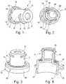
- the flange section 10 consists of a sealing section / sealing ring 14 and eight triangular connecting sections 16 which are integrally formed integrally with a triangular side on the sealing ring 14, tapering towards the lateral surface section 8 with an opposite triangular point and around the circumference of the Flange portion are evenly distributed.
- the eight triangular tips enter into punctual connections / point connections 18 with the lateral surface section 8.
- the predetermined breaking / cracking section is realized in the present embodiment.
- the predetermined breaking / cracking section is thus located on the flange section 10.
- the cover surface section 6 has a central blind hole 22 on the closure cap outer side 4.
- Fig. 2 is a perspective view of the cap 2, in particular a cap inside 20 shown. It becomes clear here first that the in Fig. 1 shown blind hole 22 on the cap inside 20 as a plug-like projection 24 is formed.
- the cover surface portion 6 has on the closure cap inside 20 two web portions / web-like projections 26, of which in Fig. 2 however, only one is visible.
- the web portions 26 are formed narrow and elongated and extend from a radial outer side of the cover surface portion 6 toward the plug-like projection 24.
- the web portions 26 are formed with respect to the cover surface portion 6 protruding / protruding.
- the second, non-visible web portion 26 is located opposite to the first web portion 26.
- the two web portions 26 are thus arranged uniformly distributed around the circumference of the cover surface portion 6.
- the closure cap 2 is in one piece in a process step and einmaterialig made by injection molding of an elastic plastic.
- Fig. 3 shows a perspective view of a fixed to a connection port 30 of a cartridge-shaped container / a cartridge cap 2.
- the connection port 30 has here a socket-like portion 34 and a pipe socket-shaped portion 36.
- the closure cap 2 is plugged onto the pipe socket-shaped section 36 of the connection port 30 and accommodated via its sealing ring 14 in a receptacle 38 of the socket-like section 34 or fastened to the socket-like section 34 of the connection port 30.
- Fig. 4 shows a perspective sectional view of the attached to the connection port 30 of the cartridge-shaped container / the cartridge cap 2.
- the web portions 26 are located on an end face 40 of the pipe socket-shaped portion 36 of the connection port 30.
- the plug-like projection 24 protrudes into the opening of the connection port 30 and seals the connection port 30 to the outside.
- no film for sealing the connection port 30 is provided.
- the sealing portion 28 fulfills an additional sealing function and abuts fully on an outer side of the pipe socket-shaped portion 36 of the connection port 30.
- a double seal is preferably provided by the sealing section 28 on the one hand and by the plug-like projection 24 on the other hand.
- the sealing ring 14 can be pressed according to this preferred embodiment, on the one hand in the annular receptacle 38 / moved.
- an outer ring portion 42 of the socket-like portion 34 is elastically displaced radially outward and springs after the signing ring is snapped or clipped, radially inwardly back, so that the signing ring is thereby positively received in the annular receptacle 38.
- the sealing ring 14 can be inserted without power into the annular receptacle and is subsequently realized by forming or bending the outer annular section 42 radially inwards, a form-locking fixation.
- FIG. 5 A second embodiment of the closure cap 2 according to the invention is shown in FIG Fig. 5 and Fig. 6 shown. How out Fig. 5 shows, the top surface portion 6 in this embodiment also has a blind hole 22. Rounded edges between the top surface portion 6 and the blind hole 22 and between the Cover surface portion 6 and the lateral surface portion 8 improve handling of the cap. 2
- the cover surface section 6 merges on the outer side of the cap 4 into a radially outwardly projecting upper outer section 44 of the lateral surface section 8.
- a radially recessed middle outer section 46 of the lateral surface section 8 adjoins the upper outer section 44 at the bottom.
- the upper, radially projecting outer portion 44 can thus be easily gripped by a user in this embodiment, whereby a removal of the cap 2 is simplified / improved by a cartridge.
- a key area polygonal profile
- the flange portion 10 of Fig. 5 has subsequent to the corrugated outer portion 48 a first radially outwardly projecting flange portion 50 which approximately forms a perimeter about the corrugated outer portion 48.
- the first radially outwardly projecting flange portion 50 is followed by triangular connecting portions 16.
- An inventive circumferential breakaway / tear section is formed between the first radially outwardly projecting flange section 50 and the triangular connection sections 16.
- the adjoining the triangular connecting portions 16 sealing portion 14 has an upper, circumferential and recessed corner portion 52, in which, for example, the in Fig. 4 shown ring portion 42 can engage.
Abstract
Die Erfindung betrifft eine Verschlusskappe (2), welche zum Befestigen, insbesondere zum Aufstecken, an einem, insbesondere rohrstutzenförmigen, Anschlussport (30) eines kartuschenförmigen Behälters vorbereitet ist und in einem montierten Zustand einem Verschließen des Anschlussports (30) dient, mit einem, insbesondere kreisförmig ausgebildeten, Deckflächenabschnitt (6), einem sich, insbesondere senkrecht und zylindrisch, an den Deckflächenabschnitt (6) anschließenden Mantelflächenabschnitt (8), und einem sich an den Mantelflächenabschnitt (8) anschließenden, insbesondere ringförmigen, Flanschabschnitt (10), wobei der Flanschabschnitt (10) einen Versiegelungsabschnitt (14), über welchen die Verschlusskappe (2) an dem kartuschenförmigen Behälter fixierbar und versiegelbar ist, und einen Sollbruch-/ - rissabschnitt (18), an welchem die Verschlussklappe (2) beim Entfernen der Verschlusskappe (2) von dem kartuschenförmigen Behälter vordefiniert reißt und/oder bricht, aufweist und/oder ausbildet.The invention relates to a closure cap (2) which is prepared for fastening, in particular for attachment, to a connection port (30) of a cartridge-shaped container, in particular in a tubular connection, and in a mounted state serves to close the connection port (30) with one, in particular circular shaped, cover surface portion (6), a, in particular perpendicular and cylindrical, to the cover surface portion (6) adjoining lateral surface portion (8), and a to the lateral surface portion (8) adjoining, in particular annular flange portion (10), wherein the flange portion (10) a sealing portion (14), via which the closure cap (2) is fixable and sealable on the cartridge-shaped container, and a predetermined breaking / tear portion (18) on which the closure flap (2) upon removal of the closure cap (2) predefined rips from the cartridge-shaped container and / or breaks, up is and / or trains.
Description
Die Erfindung betrifft eine Verschlusskappe, welche zum Befestigen an einem, insbesondere rohrstutzenförmigen, Anschlussport/ Konnektor eines kartuschenförmigen Behälters/ einer Kartusche vorbereitet ist und in einem montierten Zustand einem Verschließen des Anschlussports dient, mit einem, insbesondere rund/ kreisförmig ausgebildeten, Deckflächenabschnitt, einem sich, insbesondere senkrecht und zylindrisch, an den Deckflächenabschnitt anschließenden Mantelflächenabschnitt, und einem sich an den Mantelflächenabschnitt anschließenden, insbesondere ringförmigen, Flanschabschnitt. Außerdem betrifft die Erfindung einen kartuschenförmigen Behälter/ eine Kartusche für eine extrakorporale Blutbehandlungsmaschine, welcher/ welche zumindest einen einen Fluideinlass und/oder einen Fluidauslass bildenden, insbesondere rohrstutzenförmigen, Anschlussport und zumindest eine Verschlusskappe zum Verschließen des zumindest einen Anschlussports aufweist.The invention relates to a closure cap, which is prepared for attachment to a, in particular pipe socket-shaped, port / connector of a cartridge-shaped container / cartridge and in a mounted state serves to close the connection port, with a, in particular round / circular shaped, cover surface portion, a , in particular perpendicular and cylindrical, on the top surface portion adjoining lateral surface portion, and a subsequent to the lateral surface portion, in particular annular flange portion. In addition, the invention relates to a cartridge-shaped container / cartridge for an extracorporeal blood treatment machine, which / which has at least one a fluid inlet and / or a fluid outlet forming, in particular rohrstutzenförmigen, port and at least one cap for closing the at least one connection port.
Der Therapieerfolg der verschiedensten Dialyseverfahren beruht unter anderem auf dem Einsatz verschiedener Puffersubstanzen, mit Hilfe derer ein veränderter Säure-Basen-Haushalt von niereninsuffizienten Patienten korrigiert werden kann. Vor dem Hintergrund, dass sich der Säure-Basen-Haushalt nicht durch Diffusion während der Dialyse korrigieren lässt, ist häufig eine Zufuhr von Puffersubstanzen erforderlich. Zum Ausgleichen des Gefälles zwischen Säuren und Basen eignet sich insbesondere Bikarbonat bzw. eine Bikarbonat-Pufferlösung. Die Bikarbonat-Pufferlösung wird für die Dialyse bevorzugt erst unmittelbar vor bzw. während der Behandlung hergestellt. Dabei wird ein Behälter, insbesondere ein kartuschenförmiger Behälter/ eine Kartusche, welcher/ welche ein Bikarbonatkonzentratpulver enthält, an eine Fluidquelle, beispielsweise eine Wasserquelle angeschlossen, wobei das den Behälter durchströmende Wasser das in dem Behälter befindliche Bikarbonatkonzentratpulver auflöst und dieses in die Dialysierflüssigkeit ausschwemmt.The therapeutic success of a variety of dialysis based, inter alia, on the use of various buffer substances, with the help of which an altered acid-base balance of renal insufficiency patients can be corrected. In light of the fact that the acid-base balance can not be corrected by diffusion during dialysis, it is often necessary to introduce buffer substances. To balance the gradient between acids and bases, in particular bicarbonate or a bicarbonate buffer solution is suitable. The bicarbonate buffer solution is preferably prepared for dialysis only immediately before or during the treatment. In this case, a container, in particular a cartridge-shaped container / cartridge containing a bicarbonate concentrate powder, is connected to a fluid source, for example a water source, wherein the water flowing through the container dissolves the bicarbonate concentrate powder contained in the container and flours it into the dialysis fluid.
Die bekannten kartuschenförmigen Behälter/ Kartuschen weisen dabei grundsätzlich einen Fluideinlass-Anschlussport/ Konnektor und einen Fluidauslass-Anschlussport/ Konnektor auf, an welche jeweils eine Fluideinlassleitung und eine Fluidauslassleitung anbringbar sind. Die Anschlussports/ Konnektoren bestehen dabei grundsätzlich aus kurzen, von dem Behälter axial hervorragenden Rohrabschnitten oder Rohrstutzen. Um eine weltweit einheitliche, das heißt temperatur-, druck- und luftfeuchtigkeitsunabhängige Haltbarkeit bei Bikarbonat-Kartuschen sicherstellen bzw. garantieren zu können, ist es aus dem Stand der Technik bekannt, Verschlusskappen mit Dichtfunktion auf die rohrstutzenförmigen Anschlussports/ Konnektoren aufzustecken bzw. aufzuschrauben.The known cartridge-shaped containers / cartridges basically have a fluid inlet connection port / connector and a fluid outlet connection port / connector, to each of which a fluid inlet line and a fluid outlet line can be attached. The connection ports / connectors basically consist of short pipe sections or pipe sockets which project axially from the container. In order to ensure or guarantee worldwide uniform, ie temperature, pressure and humidity-independent durability in bicarbonate cartridges, it is known from the prior art, aufzustecken or screw caps with sealing function on the pipe socket-shaped connection ports / connectors.
Beispielsweise ist aus der
Um sicherstellen zu können, dass der kartuschenförmige Behälter/ die Kartusche noch original verschlossen ist bzw. einen Originalitätsverschluss aufweist, ist es aus dem Stand der Technik grundsätzlich bekannt, den rohrstutzenförmigen Anschlussport des Behälters/ der Kartusche mit einer Folie/ einem Foliensiegel abzudichten. Wird jedoch lediglich eine Folie zum Versiegeln an dem Anschlussport angebracht, hat dies den Nachteil, dass diese bei einer Lagerung und/ oder einem Transport beschädigt und durchstoßen werden kann. Daher wird beispielsweise in der
In der
In der
Vor diesem Hintergrund ist es Aufgabe der vorliegenden Erfindung, die Nachteile aus dem Stand der Technik zu vermeiden oder wenigstens zu mildern. Insbesondere soll eine Verschlusskappe für einen, insbesondere kartuschenförmigen, Behälter/ eine Kartusche bereitgestellt werden, welche in einfacher Weise handhabbar ist und einen für einen Anwender schnell und einfach zu überprüfenden, versiegelten Originalitätsverschluss bereitstellt. Insbesondere ist es Aufgabe der Erfindung, eine sofortige Sichtprüfung des Originalitätsverschlusses zu ermöglichen. Zudem soll ein erneutes Anbringen der Verschlusskappe zu Entsorgungszwecken verbessert werden. Diese Aufgabe wird durch eine Verschlussklappe nach Anspruch 1 und einen kartuschenförmigen Behälter/ eine Kartusche nach Anspruch 10 gelöst. Vorteilhafte Ausführungsformen und Weiterbildungen sind in den Unteransprüchen beansprucht und/ oder nachfolgend erläutert.Against this background, it is an object of the present invention to avoid or at least mitigate the disadvantages of the prior art. In particular, a closure cap for a, in particular cartridge-shaped, container / a cartridge is to be provided which can be handled in a simple manner and provides a quick and easy to check for a user, sealed tamper-evident closure. In particular, it is an object of the invention to enable an immediate visual inspection of the tamper-evident closure. In addition, a re-attaching the cap for disposal purposes should be improved. This object is achieved by a closure flap according to claim 1 and a cartridge-shaped container / a cartridge according to
Die Erfindung betrifft zunächst eine, insbesondere eine stoßdämpfende Wirkung aufweisende, Verschlusskappe, welche zum Befestigen, insbesondere zum Aufstecken, an einem, insbesondere rohrstutzenförmigen, Anschlussport/ Konnektor eines kartuschenförmigen Behälters/ einer Kartusche vorbereitet ist und in einem montierten Zustand einem Verschließen des Anschlussports dient, mit einem, insbesondere runden/ rund/kreisförmig ausgebildeten, Deckflächenabschnitt, einem sich, insbesondere senkrecht, an den Deckflächenabschnitt anschließenden, bevorzugt im Wesentlichen zylindrisch verlaufenden, Mantelflächenabschnitt, und einem sich an den Mantelflächenabschnitt anschließenden, insbesondere ringförmigen, bevorzugt sich endseitig des Mantelflächenabschnitts von dem Mantelflächenabschnitt senkrecht und radial nach außen weg erstreckenden, Flanschabschnitt, wobei der Flanschabschnitt einen Versiegelungsabschnitt, über welchen die Verschlusskappe an dem kartuschenförmigen Behälter/ der Kartusche fixierbar und versiegelbar ist, und einen Sollbruch-/ -rissabschnitt, an welchem die Verschlussklappe beim Entfernen der Verschlusskappe von dem kartuschenförmigen Behälter/ der Kartusche vordefiniert reißt und/oder bricht, aufweist und/oder ausbildet.The invention relates to a first, in particular a shock-absorbing effect, having closure cap which is prepared for fastening, in particular for attachment to a, in particular rohrstutzenförmigen, connection port / connector of a cartridge-shaped container / a cartridge and serves in a mounted state, a closing of the connection port, with a, in particular round / circular / circular-shaped, cover surface portion, a, in particular perpendicular, adjoining the top surface portion, preferably substantially cylindrical extending lateral surface portion, and adjoining the lateral surface portion, in particular annular, preferably end side of the lateral surface portion of the Jacket surface portion perpendicular and radially outwardly extending, flange portion, wherein the flange portion has a sealing portion, via which the closure cap on the cartridge-shaped container he / the cartridge is fixable and sealable, and a predetermined breaking / tear portion at which the closure flap on removal of the cap of the cartridge-shaped container / cartridge tears and / or predefined breaks, has and / or forms.
Es wird somit in anderen Worten erfindungsgemäß eine Verschlusskappe in der Form eines sacklochartig ausgenommenen Zylinders bereitgestellt, welche an ihrem offenen Ende einen, sich insbesondere von dem Mantelflächenabschnitt radial, vorzugsweise senkrecht, nach außen erstreckenden, Flanschabschnitt aufweist. Die Verschlusskappe kann in einfacher Weise durch Aufstecken auf einen Anschlussport eines kartuschenförmigen Behälters/ einer Kartusche, welcher/ welche Pulverpartikel, etwa Bikarbonat, Natriumchlorid oder Ähnliches, beinhaltet, angebracht werden, so dass insbesondere ein geschlossenes, das heißt versiegeltes und/oder abgedichtetes, Kartuschensystem mit Hilfe bzw. durch die erfindungsgemäße Verschlusskappe/ Kappe/ Abdeckkappe entstehen kann. Die Verschlusskappe hat zudem eine Schutzfunktion für den Anschlussport und verhindert, dass dieser in irgendeiner Weise beschädigt werden kann.In other words, according to the invention, there is thus provided a closure cap in the form of a cylinder hole-like recessed cylinder, which at its open end has a flange section which extends radially, preferably vertically, outwardly from the lateral surface section. The cap can be easily attached by plugging onto a port of a cartridge-shaped container / cartridge containing powder particles such as bicarbonate, sodium chloride or the like, so that in particular a closed, ie sealed and / or sealed cartridge system can arise with the help or through the closure cap / cap / cap according to the invention. The cap also has a Protection function for the connection port and prevents it from being damaged in any way.
Der Flanschabschnitt weist dabei einen Versiegelungsabschnitt, insbesondere Siegelring, auf, über welchen die Verschlusskappe an dem kartuschenförmigen Behälter/ der Kartusche bzw. dem Anschlussport versiegelt und befestigt/ fixiert werden kann. Der Versiegelungsabschnitt dient in anderen Worten einem Befestigen und einem Versiegeln der Verschlusskappe an dem kartuschenförmigen Behälter/ der Kartusche/ dem Anschlussport. Im an dem kartuschenförmigen Behälter/ der Kartusche fixierten/ befestigten Zustand der Verschlusskappe wird dadurch ein Originalitätsverschluss bereitgestellt. Der Versiegelungsabschnitt ist vorzugsweise an einer radialen Außenseite des Flanschabschnitts vorgesehen. Der Versiegelungsabschnitt/ der Siegelring kann erfindungsgemäß zinnenförmig ausgebildet sein.In this case, the flange section has a sealing section, in particular a sealing ring, via which the closure cap can be sealed and fixed / fixed to the cartridge-shaped container / cartridge or the connection port. In other words, the sealing portion serves to attach and seal the closure cap to the cartridge-shaped container / cartridge / port. In the state of the closure cap fixed / fastened to the cartridge-shaped container / cartridge, a tamper-evident closure is thereby provided. The sealing portion is preferably provided on a radial outside of the flange portion. The sealing portion / the sealing ring may be crenellated according to the invention.
Wenn nun der Flanschabschnitt neben dem/ zusätzlich zu dem Versiegelungsabschnitt einen Sollbruch-/ -rissabschnitt, an welchem die Verschlusskappe beim Entfernen der Verschlusskappe von dem kartuschenförmigen Behälter/ der Kartusche vordefiniert reißt und/oder bricht, aufweist und/oder ausbildet, dann kann ein Anwender sofort bei Betrachtung des sich radial nach außen erstreckenden Flanschabschnitts, das heißt auf den ersten Blick, erkennen, ob der kartuschenförmige Behälter/ die Kartusche noch original verschlossen ist oder bereits geöffnet wurde. In anderen Worten ist der Kerngedanke der Erfindung der, dass ein Sollbruch-/ -rissabschnitt, an welchem die Verschlusskappe bei deren Entfernen von dem kartuschenförmigen Behälter/ der Kartusche vordefiniert reißen oder brechen soll, an dem Flanschabschnitt vorgesehen ist. Dadurch kann ein Anwender einfacher und schneller als bei einem an einer Mantelfläche/ einem Mantelflächenabschnitt vorgesehenen Sollbruch-/ -rissabschnitt erkennen, ob der kartuschenförmige Behälter/ die Kartusche noch original verschlossen ist oder nicht, was mit einer verbesserten Handhabung des Behälters/ der Kartusche einhergeht. Insbesondere bei axialer Betrachtung des kartuschenförmigen Behälters/ der Kartusche wird somit ein leichteres Erkennen eines vorliegenden Originalitätsverschlusses ermöglicht.Now, if the flange portion adjacent to / in addition to the seal portion has a break / tear portion at which the closure cap tears and / or breaks, pre-defines and / or breaks upon removal of the closure cap from the cartridge-shaped container / cartridge, then a user may Immediately upon viewing the radially outwardly extending flange portion, that is, at first glance, recognize whether the cartridge-shaped container / the cartridge is still originally closed or has already been opened. In other words, the gist of the invention is that a predetermined break / tear portion at which the closure cap is predefined to tear or break when removed from the cartridge-shaped container / cartridge is provided on the flange portion. As a result, a user can recognize more easily and more quickly than in the case of a predetermined break / tear section provided on a lateral surface / lateral surface section as to whether the cartridge-shaped container / cartridge is still originally sealed or not, which results in improved handling of the container / cartridge. In particular, when the cartridge-shaped container / cartridge is viewed axially, an easier detection of a present tamper-evident closure is thus made possible.
In vorteilhafter Weise ist der Sollbruch-/ -rissabschnitt des Flanschabschnitts an einem Übergangsbereich zu dem Mantelflächenabschnitt vorgesehenen und als zumindest eine Sollbruchstelle und/oder eine Sollrisslinie ausgebildet, an welcher die Verschlusskappe beim Entfernen der Verschlusskappe von dem kartuschenförmigen Behälter/ der Kartusche derart abreißt und/oder bricht, dass der Versiegelungsabschnitt der Verschlusskappe an dem kartuschenförmigen Behälter/ der Kartusche verbleibt und die übrige Verschlusskappe bestehend aus Mantelflächen-/ und Deckflächenabschnitt von dem kartuschenförmigen Behälter/ der Kartusche lösbar ist.In an advantageous manner, the predetermined breaking / cracking section of the flange section is provided at a transition area to the lateral surface section and designed as at least one predetermined breaking point and / or a predetermined tear line at which the closure cap thus tears off from the cartridge-shaped container / cartridge during removal of the closure cap and / or or breaks the sealing portion of the closure cap remaining on the cartridge-shaped container / cartridge and the remaining closure cap consisting of lateral surface and top surface portions is detachable from the cartridge-shaped container / cartridge.
Der Sollbruch-/ -rissabschnitt kann somit als durchgehende, umlaufende, insbesondere perforierte oder durchlochte, Sollrisslinie oder als eine Sollbruchstelle/ eine Vielzahl von Sollbruchstellen ausgebildet sein. Insbesondere stellt der Sollbruch-/ -rissabschnitt einen geschwächten Abschnitt des Flanschabschnitts dar. Dies wird generell dadurch erreicht, dass an dem Sollbruch-/ -rissabschnitt weniger Material/ eine geringere Wandstärke/ Perforationen/ Ausnehmungen/ Löcher oder Ähnliches vorgesehen sind. Dies hat den Effekt, dass bei einem Aufbringen einer Kraft zum Entfernen der Verschlusskappe ein definierter Riss/ Bruch an einer vorbestimmten Stelle an dem Flanschabschnitt erfolgt und gleichzeitig der Versiegelungsabschnitt weiterhin fixiert/ befestigt an dem kartuschenförmigen Behälter/ der Kartusche verbleibt.The predetermined breaking / cracking section can thus be designed as a continuous, circumferential, in particular perforated or pierced, predetermined tear line or as a predetermined breaking point / a plurality of predetermined breaking points. In particular, the predetermined break / tear section constitutes a weakened section of the flange section. This is generally accomplished by providing less material / wall thickness / perforations / recesses / holes or the like at the break / tear section. This has the effect that when a force is applied to remove the closure cap, a defined crack occurs at a predetermined location on the flange portion and at the same time the sealing portion remains fixed to the cartridge-shaped container / cartridge.
Erfindungsgemäß ist somit eine erforderliche Kraft zum Herausreißen/ Entfernen des Versiegelungsabschnitts von dem kartuschenförmigen Behälter/ der Kartusche größer als eine Kraft, welche zum Reißen/ Brechen der Verschlusskappe an dem Sollbruch-/ - rissabschnitt vonnöten ist. Ein Anwender weiß somit, dass die Verschlusskappe nur an einer vorbestimmten Stelle brechen bzw. reißen kann bzw. sollte, wodurch eine Sichtprüfung in großem Maße erleichtert wird. Vor diesem Hintergrund kann ein Anwender auch darauf schließen, dass der kartuschenförmige Behälter/ die Kartusche vor dem Öffnen desselben/ derselben in geeigneter Weise versiegelt war, wenn der Siegelring/ Versiegelungsabschnitt nach dem Öffnen des Behälters noch fest befestigt/ fixiert an dem kartuschenförmigen Behälter/ der Kartusche/ dem Anschlussport vorliegt.Thus, in accordance with the present invention, a force required to pull / remove the seal portion from the cartridge-shaped container / cartridge is greater than a force required to rupture / break the closure cap at the rupture portion. A user thus knows that the cap can or should break only at a predetermined location, thereby greatly facilitating visual inspection. In view of this, a user can also conclude that the cartridge-shaped container / cartridge has been suitably sealed before opening the same when the sealing ring / seal portion is still firmly fixed / fixed to the cartridge-shaped container after opening the container Cartridge / the connection port is present.
Ein vorteilhaftes Ausführungsbeispiel ist dadurch gekennzeichnet, dass der Versiegelungsabschnitt eine Vielzahl von Ausnehmungen aufweist, und zwar derart, dass er aus einem umlaufenden Versiegelungsringabschnitt und einer Vielzahl von, insbesondere dreieckförmigen, Verbindungsabschnitten besteht, wobei die Verbindungsabschnitte punktuell mit dem Mantelflächenabschnitt verbunden sind und der Sollbruch-/ -rissabschnitt durch die Vielzahl an punktuellen Verbindungen ausgebildet ist.An advantageous embodiment is characterized in that the sealing portion has a plurality of recesses, in such a way, that it consists of a circumferential sealing ring portion and a plurality of, in particular triangular, connecting portions, wherein the connecting portions are selectively connected to the lateral surface portion and the predetermined breaking / -rissabschnitt is formed by the plurality of punctiform connections.
Gemäß einer bevorzugten erfindungsgemäßen Ausführungsform ist somit ein umlaufender Ringabschnitt/ Versiegelungsringabschnitt an dem kartuschenförmigen Behälter/ der Kartusche/ dem Anschlussport fixiert/ befestigt. Dieser Ringabschnitt befindet sich an einer radialen Außenseite des Flanschabschnitts. Von dem Ringabschnitt erstrecken sich viele, insbesondere acht, dreieckförmige Verbindungsabschnitte zu dem Mantelflächenabschnitt hin und kontaktieren den Mantelflächenabschnitt punktuell mit einer Dreiecksspitze. Dadurch entstehen viele, insbesondere acht, punktuelle Verbindungen zwischen dem Flanschabschnitt und dem Mantelflächenabschnitt. Die Gesamtheit der punktuellen Verbindungen dieser Ausführungsform bildet den erfindungsgemäßen Sollbruch-/ -rissabschnitt. Wird die Verschlusskappe dieser Ausführungsform gedreht und/ oder an dieser gezogen, reißen/ brechen die punktuellen Verbindungen, so dass die Verschlusskappe, nunmehr bestehend aus Mantelflächenabschnitt und Deckflächenabschnitt, abgezogen werden kann und der Versiegelungsabschnitt an dem kartuschenförmigen Behälter/ der Kartusche/ dem Anschlussport verbleibt.Thus, according to a preferred embodiment of the invention, a circumferential annular portion / sealing ring portion is fixed / attached to the cartridge-shaped container / cartridge / port. This ring portion is located on a radial outer side of the flange portion. From the ring portion, many, in particular eight, triangular connecting portions extend to the lateral surface portion and contact the lateral surface portion selectively with a triangular point. This results in many, in particular eight, selective connections between the flange portion and the lateral surface portion. The entirety of the punctiform connections of this embodiment forms the predetermined break / tear section according to the invention. When the closure cap of this embodiment is rotated and / or pulled, the punctiform connections rupture, so that the closure cap, now consisting of lateral surface portion and top surface portion, can be pulled off and the sealing portion remains on the cartridge-shaped container / cartridge / connection port.
Außerdem kann es vorgesehen sein, dass der Sollbruch-/ -rissabschnitt als eine perforierte, insbesondere durchlochte, umlaufende Sollrisslinie, insbesondere Perforationssollrisslinie, ausgebildet ist.In addition, it can be provided that the predetermined breaking / cracking section is designed as a perforated, in particular perforated, peripheral tear line, in particular perforation tear line.
Gemäß einer zweiten bevorzugten erfindungsgemäßen Ausführungsform ist der Flanschabschnitt somit von dem Mantelflächenabschnitt bis hin zu seiner radialen Außenseite als durchgehender Vollmaterialabschnitt ausgebildet und weist lediglich an oder nahe einem Übergangsbereich zu dem Mantelflächenabschnitt eine perforierte Sollrisslinie auf. In anderen Worten wird der Sollbruch-/ -rissabschnitt gemäß dieser Ausführungsform durch viele, eng aneinander gereihte/ liegende Perforationen/ kleine Löcher ausgebildet.According to a second preferred embodiment of the invention, the flange portion is thus formed from the lateral surface portion to its radial outer side as a continuous solid material portion and has only at or near a transition region to the lateral surface portion on a perforated predetermined tear. In other words, the frangible breaking / cracking portion according to this embodiment is formed by many closely spaced / lying perforations / small holes.
Ferner kann erfindungsgemäß der Sollbruch-/ -rissabschnitt auch durchgehend undurchlocht bzw. unperforiert, beispielsweise durch eine verringerte Materialdicke, ausgebildet sein. Eine derartige Ausführungsform hat eine verbesserte Abdichtung bzw. Abdichtwirkung zur Folge. Der Sollbruch-/ rissabschnitt stellt jedoch in jedem Fall - wie in allen Ausführungsformen der vorliegenden Erfindung - eine zumindest abschnittsweise Schwachstelle an dem Flanschabschnitt der Verschlusskappe dar.Furthermore, according to the invention, the predetermined breaking / cracking section can also be continuously perforated or unperforated, for example by a reduced material thickness. Such an embodiment results in an improved sealing or sealing effect. However, the predetermined breaking / cracking section represents, as in all embodiments of the present invention, an at least partially weak point on the flange portion of the closure cap.
Es kann außerdem vorgesehen sein, dass sowohl der Flanschabschnitt als auch der Mantelflächenabschnitt jeweils zumindest einen Sollbruch-/ -rissabschnitt aufweisen und die Sollbruch-/ -rissabschnitte des Flanschabschnitts und des Mantelflächenabschnitts umlaufend ineinander übergehen. Gemäß dieser Ausführungsform ist somit eine umlaufende Sollrisslinie vorgesehen, welche abwechselnd von dem Flanschabschnitt zu dem Mantelflächenabschnitt übergeht und umgekehrt. Weiter bevorzugt liegt genau ein Sollbruch-/ -rissabschnitt an dem Flanschabschnitt vor, welcher nach einer 180°-Drehung zu einem Sollbruch-/ - rissabschnitt an dem Mantelflächenabschnitt übergeht. Nach einer 180°-Drehung des Sollbruch-/ -rissabschnitts an dem Mantelflächenabschnitt erfolgt wieder ein Übergang zu dem Sollbruch-/ -rissabschnitt an dem Flanschabschnitt.It may also be provided that both the flange portion and the lateral surface portion each have at least one predetermined breaking / cracking section and the predetermined breaking / cracking portions of the flange portion and the lateral surface portion circumferentially merge into one another. According to this embodiment, therefore, a circumferential tear line is provided, which alternates from the flange portion to the lateral surface portion and vice versa. More preferably, exactly one predetermined breaking / cracking section is present at the flange section which, after a 180 ° turn, merges into a predetermined breaking / cracking section on the lateral surface section. After a 180 ° rotation of the predetermined breaking / tear section on the lateral surface section, there is again a transition to the predetermined breaking / cracking section on the flange section.
Es ist von Vorteil, wenn die Verschlusskappe als eine Aufsteckkappe ausgeführt ist und der Versiegelungsabschnitt des Flanschabschnitts formschlüssig in einer an dem kartuschenförmigen Behälter/ der Kartusche vorgesehenen Aufnahme, insbesondere durch Bördeln oder Einpressen, aufgenommen und/oder an dem kartuschenförmigen Behälter/ der Kartusche befestigt ist.It is advantageous if the closure cap is designed as a slip-on cap and the sealing portion of the flange portion is positively received in a receptacle provided on the cartridge-shaped container / cartridge, in particular by crimping or pressing, and / or attached to the cartridge-shaped container / cartridge ,
Dadurch dass die Verschlusskappe als eine Aufsteckkappe ausgeführt ist, ist kein aufwändiges Aufschrauben derselben vonnöten. Eine Handhabung wird dadurch vereinfacht. Wird der Versiegelungsabschnitt, welcher insbesondere als ein Brechsiegel ausgebildet ist, formschlüssig in einer an dem kartuschenförmigen Behälter/ der Kartusche/ dem Anschlussport vorgesehenen Aufnahme aufgenommen/ befestigt, kann ein Fixieren/ Versiegeln der Verschlusskappe an dem kartuschenförmigen Behälter/ der Kartusche in einem einzigen Prozessschritt, vorzugsweise vollautomatisch, erfolgen. Bevorzugt wird die Verschlusskappe im Rahmen einer vollautomatischen Produktionsanlage an dem kartuschenförmigen Behälter/ der Kartusche befestigt. Dabei wird die Verschlusskappe in einem ersten Schritt auf den Anschlussport aufgesteckt. In einem zweiten Schritt wird der Versiegelungsabschnitt mit Hilfe eines Einpresswerkzeugs/ eines umformenden/ umwölbenden Werkzeugs, insbesondere Bördelwerkzeugs, in die Aufnahme gedrückt/ gepresst/ umgeformt/ eingerastet/ geschweißt/ aufgeklipst und damit formschlüssig in der Aufnahme aufgenommen. Außerdem kann der Formschluss durch ein Umformen von Abschnitten des kartuschenförmigen Behälters/ der Kartusche/ des Anschlussports und ein dadurch bewirktes Einklemmen des Versiegelungsabschnitts bewirkt werden.The fact that the cap is designed as a Aufsteckkappe, no elaborate screwing the same is needed. Handling is simplified. If the sealing section, which is designed in particular as a crushing seal, is positively received / secured in a receptacle provided on the cartridge-shaped receptacle / cartridge / connection port, fixing / sealing of the closure cap to the cartridge-shaped receptacle / cartridge can take place in a single process step, preferably fully automatic, done. The closure cap is preferably fastened to the cartridge-shaped container / cartridge as part of a fully automatic production system. The cap is then plugged onto the connection port in a first step. In a second step, the sealing portion is pressed / pressed / formed / locked / welded / clipped with the aid of a press tool / a deforming / bulging tool, in particular crimping tool into the receptacle and thus positively received in the receptacle. In addition, the positive engagement may be effected by reshaping portions of the cartridge-shaped container / cartridge / port and thereby pinching the sealing portion.
Es sei angeführt, dass erfindungsgemäß eine formschlüssige Verbindung des Versiegelungsabschnitt mit der an dem kartuschenförmigen Behälter/ der Kartusche vorgesehenen Aufnahme durch Bördeln oder Einpressen zwar bevorzugt ist, jedoch auch eine stoffschlüssige Verbindung durch Schweißen oder eine kraft- und formschlüssige Verbindung durch Nieten vorgesehen sein kann. Insbesondere soll eine von vielen denkbaren Verbindungsarten gewählt werden, welche die Verschlusskappe geeignet an dem kartuschenförmigen Behälter/ der Kartusche/ dem Anschlussport befestigen und versiegeln kann und die Verschlusskappe gegen ein Abrutschen bzw. Lösen von dem Anschlussport schützt.It should be noted that according to the invention a positive connection of the sealing portion with the provided on the cartridge-shaped container / cartridge receptacle by crimping or pressing is indeed preferred, but also a cohesive connection by welding or a non-positive and positive connection can be provided by rivets. In particular, one of many conceivable types of connection is to be selected, which can attach and seal the cap suitably to the cartridge-shaped container / cartridge / the port and protects the cap against slipping or loosening of the connection port.
Außerdem ist es zweckmäßig, wenn die Verschlusskappe an einer Verschlusskappeninnenseite an dem Deckflächenabschnitt und/oder dem Mantelflächenabschnitt zumindest ein Dichtelement zum Abdichten des Anschlussports des kartuschenförmigen Behälters aufweist.In addition, it is expedient for the closure cap to have at least one sealing element for sealing the connection port of the cartridge-shaped container on a closure cap inside the top surface section and / or the lateral surface section.
Um das geschlossene Kartuschensystem der vorliegenden Erfindung bereitstellen zu können, ist es essentiell, für eine geeignete Abdichtung nach außen zu sorgen, damit die Haltbarkeit des kartuschenförmigen Behälters/ der Kartusche unabhängig von der Klimazone ist, in welcher sie verwendet wird. Bei einer erhöhten Außentemperatur, Druck und Luftfeuchtigkeit kann nämlich bei Bikarbonatkartuschen der Karbonatwert schneller ansteigen, was mit einer verkürzten Haltbarkeit einhergehen würde. Daher ist die Abdichtung ein grundlegender Aspekt der vorliegenden Erfindung.In order to be able to provide the closed cartridge system of the present invention, it is essential to provide a suitable seal to the outside, so that the durability of the cartridge-shaped container / cartridge is independent of the climatic zone in which it is used. With increased outside temperature, pressure and humidity, bicarbonate cartridges can increase the carbonate value faster, which would be accompanied by a shortened shelf life. Therefore, the seal is a fundamental aspect of the present invention.
Die Abdichtung wird erfindungsgemäß durch einstückig/ einmaterialig an einer Verschlusskappeninnenseite angeformte Dichtelemente realisiert. In anderen Worten werden die Dichtelemente durch eine geeignete konstruktive Gestaltung bzw. Materialauswahl der erfindungsgemäßen Verschlusskappe ausgebildet. Bevorzugt ist zumindest eine umlaufende Dichtlippe an dem Mantelflächenabschnitt an der Verschlusskappeninnenseite vorgesehen, welche zum Beispiel durch ein abschnittsweises Erhöhen/ Vergrößern der Wandstärke des Mantelflächenabschnitts konstruktiv umsetzbar ist. Es können jedoch auch zwei, drei, vier oder mehr umflaufende Dichtlippen bzw. Dichtelemente an dem Mantelflächenabschnitt vorgesehen sein.The seal is realized according to the invention by one piece / einmaterialig formed on a cap inside sealing elements. In other words, the sealing elements are formed by a suitable structural design or material selection of the closure cap according to the invention. Preferably, at least one circumferential sealing lip is provided on the lateral surface section on the inner side of the closure cap, which can be implemented constructively, for example, by increasing / enlarging the wall thickness of the lateral surface section in sections. However, two, three, four or more circumferential sealing lips or sealing elements may also be provided on the lateral surface section.
Erfindungsgemäß sind verschiedene Ausführungsarten von Dichtelementen denkbar. Wichtig ist jedoch, dass die Dichtelemente einstückig/ einmaterialig, insbesondere im Spritzgussverfahren, in einem Prozessschritt mit der Verschlusskappe gefertigt werden und an einer Verschlusskappeninnenseite angeformt sind. Insbesondere soll eine Funktionselastizität und Materialelastizität der Dichtelemente durch deren Geometrie und dem verwendeten Material erzeugt bzw. bereitgestellt werden.Various embodiments of sealing elements are conceivable according to the invention. However, it is important that the sealing elements are manufactured in one piece / one-material, in particular by injection molding, in a process step with the closure cap and are integrally formed on a closure cap inside. In particular, a functional elasticity and material elasticity of the sealing elements should be generated or provided by their geometry and the material used.
Eine Dichtwirkung kann erfindungsgemäß auch durch ein an dem Deckflächenabschnitt angeformtes, stopfenartiges, zentrales Mittelteil, welches einstückig und einmaterialig mit der Verschlusskappe ausgeführt ist und ebenso an der Verschlusskappeninnenseite vorgesehen ist, realisiert werden. Die Verschlusskappe soll erfindungsgemäß den Anschlussport lediglich durch eine Steck-/ Aufsteckverbindung und somit ohne Gewinde abdichten.A sealing effect according to the invention can also be realized by means of a stop-like, central middle part, which is formed integrally and in one material with the closure cap and is likewise provided on the inside of the closure cap. The cap according to the invention is intended to seal the connection port only by a plug / Aufsteckverbindung and thus without thread.
In vorteilhafter Weise sind an dem Deckflächenabschnitt an einer Verschlusskappeninnenseite zumindest ein, vorzugsweise zumindest zwei, stegartige Vorsprünge vorgesehen, welche in einem montierten Zustand der Verschlusskappe einen Auflageflächenabschnitt der Verschlusskappe auf einer Stirnfläche des, insbesondere rohrstutzenförmigen, Anschlussports darstellen.In an advantageous manner, at least one, preferably at least two, web-like projections are provided on the cover surface section on a closure cap inside, which in a mounted state of the closure cap represent a bearing surface section of the closure cap on an end face of the connection port, in particular a pipe connection.
Durch die an dem Deckflächenabschnitt der Verschlusskappe vorgesehenen und somit oben liegenden, radialen Kunststoffstege, welche vorzugsweise schmal/ langgestreckt ausgebildet und einstückig/ einmaterialig an der Verschlusskappe angeformt sind, wird eine geeignete Stoßdämpfung bereitgestellt und somit der Anschlussport des kartuschenförmigen Behälters/ der Kartusche in deutlich verbesserter Weise geschützt. Es hat sich in Versuchsreihen herausgestellt, dass dadurch, dass lediglich einzelne stegartige Vorsprünge der Verschlusskappe an der Stirnfläche des Anschlussports anliegen, die Schutzwirkung und Stoßdämpfung der Verschlusskappe deutlich verbessert wird und somit eine Beschädigung des Anschlussports verhindert wird.By provided on the top surface portion of the cap and thus overhead radial plastic webs, which are preferably formed narrow / elongated and integrally molded / einmaterialig on the cap, a suitable shock absorption is provided and thus the port of the cartridge-shaped container / cartridge in significantly improved Way protected. It has been found in test series that the fact that only individual web-like projections of the cap abut the end face of the connection port, the protective effect and shock absorption of the cap is significantly improved and thus damage to the connection port is prevented.
Ferner ist es von Vorteil, wenn der Mantelflächenabschnitt der Verschlusskappe an einer Verschlusskappenaußenseite zumindest einen flügelförmig ausgebildeten, vorstehenden Griffabschnitt zur verbesserten Handhabung der Verschlusskappe aufweist.Further, it is advantageous if the lateral surface portion of the closure cap on a cap outside has at least one wing-shaped projecting handle portion for improved handling of the cap.
Flügelförmig ausgebildete, vorstehende bzw. hervorragende Griffabschnitte verbessern eine Handhabbarkeit und damit ein Abziehen der Kappe/ Verschlusskappe. Es können dabei einer oder mehrere flügelförmige Griffabschnitte vorgesehen sein. Neben flügelförmigen Vorsprüngen sind auch kreuzförmige Vorsprünge erfindungsgemäß denkbar. Außerdem kann eine Deckflächen- bzw. Mantelflächenaußenseite der Verschlusskappe geriffelt oder gummiert ausgebildet sein, um eine Griffigkeit der Kappe zu verbessern.Wing-shaped, protruding or outstanding grip sections improve handling and thus removal of the cap / cap. One or more wing-shaped grip sections can be provided. In addition to wing-shaped projections and cross-shaped projections according to the invention are conceivable. In addition, a top surface of the closure cap may be grooved or gummed to improve a grip of the cap.
Es ist zweckmäßig, wenn die Verschlusskappe aus einem elastischen Kunststoffmaterial, insbesondere einem Elastomer oder einem thermoplastischen Elastomer, ausgebildet ist und/oder als einstückiges und einmaterialiges im Spritzgussverfahren hergestelltes Kunststoffbauteil ausgebildet ist.It is expedient if the closure cap is formed from an elastic plastic material, in particular an elastomer or a thermoplastic elastomer, and / or is formed as a one-piece and one-piece plastic component produced by injection molding.
Elastische Materialeigenschaften der Verschlusskappe sind dabei erfindungsgemäß in vielerlei Hinsicht vonnöten und stellen somit ebenfalls einen zentralen Aspekt der vorliegenden Erfindung dar. Insbesondere wird dadurch sowohl eine Dichtigkeit der Verschlusskappe verbessert, als auch ein optimierter Schutz des Anschlussports erreicht, als auch eine stoßdämpfende Wirkung der Verschlusskappe verbessert.Elastic material properties of the closure cap are required according to the invention in many respects and thus also constitute a central aspect of the present invention. In particular, both a tightness of the cap is improved, as well as an optimized protection of the connection port achieved as well as a shock-absorbing effect of the cap improved ,
Die gesamte Verschlusskappe wird vorzugsweise in einem einzigen Prozessschritt als einmaterialiges und einstückiges bzw. integrales Kunststoffbauteil im Spritzgussverfahren hergestellt.The entire closure cap is preferably produced in a single process step as a one-piece and one-piece or integral plastic component by injection molding.
Gemäß einem weiteren Aspekt der vorliegenden Erfindung kann zusätzlich ein Etikett abschnittsweise an der Verschlusskappe und abschnittsweise an dem kartuschenförmigen Behälter/ der Kartusche/ dem Anschlussport vorgesehen/ angebracht sein, über welches eine zusätzliche Versiegelung erfolgt und ein vorliegender Originalitätsverschluss auf den ersten Blick sichtbar wird.In accordance with a further aspect of the present invention, a label may additionally be provided / mounted in sections on the closure cap and in sections on the cartridge-shaped container / cartridge / port, via which an additional sealing takes place and an existing tamper evident closure becomes visible at first glance.
Außerdem betrifft die Erfindung einen kartuschenförmigen Behälter/ eine Kartusche für eine extrakorporale Blutbehandlungsmaschine, welcher/ welche zumindest einen einen Fluideinlass und/oder einen Fluidauslass bildenden, insbesondere rohrstutzenförmigen, Anschlussport/ Konnektor aufweist, und zumindest einer Verschlusskappe wie voranstehend beschrieben zum Verschließen und Versiegeln des zumindest einen Anschlussports.In addition, the invention relates to a cartridge-shaped container / cartridge for an extracorporeal blood treatment machine, which / has at least one connection port / connector forming a fluid inlet and / or a fluid outlet, in particular rohrstutzenförmigen, and at least one cap as described above for sealing and sealing the at least a connection port.
Die Erfindung wird nachfolgend mit Hilfe von Figuren weiter erläutert. Es zeigen:
- Fig. 1
- eine perspektivische Ansicht einer Verschlusskappenaußenseite der erfindungsgemäßen Verschlusskappe;
- Fig. 2
- eine perspektivische Ansicht einer Verschlusskappeninnenseite der erfindungsgemäßen Verschlusskappe;
- Fig. 3
- eine perspektivische Ansicht einer an einem Anschlussport eines kartuschenförmigen Behälters/ einer Kartusche fixierten erfindungsgemäßen Verschlusskappe;
- Fig. 4
- eine perspektivische Schnittansicht der an dem Anschlussport des kartuschenförmigen Behälters/ der Kartusche fixierten erfindungsgemäßen Verschlusskappe;
- Fig. 5
- eine perspektivische Ansicht einer zweiten Ausführungsform der erfindungsgemäßen Verschlusskappe; und
- Fig. 6
- eine perspektivische Schnittansicht der Verschlusskappe der
Fig. 5 .
- Fig. 1
- a perspective view of a cap outside the cap of the invention;
- Fig. 2
- a perspective view of a cap inside the cap according to the invention;
- Fig. 3
- a perspective view of a fixed to a connection port of a cartridge-shaped container / a cartridge cap according to the invention;
- Fig. 4
- a perspective sectional view of the attached to the port of the cartridge-shaped container / cartridge closure cap according to the invention;
- Fig. 5
- a perspective view of a second embodiment of the closure cap according to the invention; and
- Fig. 6
- a sectional perspective view of the cap of the
Fig. 5 ,
Die Figuren sind lediglich schematischer Natur und dienen ausschließlich dem Verständnis der Erfindung. Gleiche Elemente sind dabei mit denselben Bezugszeichen versehen. Die Merkmale der einzelnen Ausführungsformen/ -beispiele können untereinander ausgetauscht werden.The figures are merely schematic in nature and are for the sole purpose of understanding the invention. The same elements are provided with the same reference numerals. The features of the individual embodiments / examples can be interchanged.
In
Der Flanschabschnitt 10 besteht in dieser bevorzugten erfindungsgemäßen Ausführungsform aus einem Versiegelungsabschnitt/ Siegelring 14 und acht dreieckigen Verbindungsabschnitten 16, welche jeweils mit einer Dreiecksseite an dem Siegelring 14 einstückig anliegend angeformt, mit einer gegenüberliegenden Dreiecksspitze auf den Mantelflächenabschnitt 8 zulaufend ausgebildet sind und um den Umfang des Flanschabschnitts gleichmäßig verteilt sind. Die acht Dreiecksspitzen gehen punktuelle Verbindungen/ Punktverbindungen 18 mit dem Mantelflächenabschnitt 8 ein. Durch die Gesamtheit der acht punktuellen Verbindungen 18 wird in der vorliegenden Ausführungsform der erfindungsgemäße Sollbruch-/ - rissabschnitt realisiert. Der Sollbruch-/ -rissabschnitt befindet sich somit an dem Flanschabschnitt 10. Der Deckflächenabschnitt 6 weist an der Verschlusskappenaußenseite 4 ein zentrales Sackloch 22 auf.In this preferred embodiment according to the invention, the
In
An einem Mittelabschnitt des Mantelflächenabschnitts 8 ist an der Verschlusskappeninnenseite 20 ein umlaufender Dichtabschnitt 28 vorgesehen, welcher nach Art einer Dichtlippe ausgebildet ist. Es können jedoch auch zwei, drei, vier oder mehr umlaufende Dichtabschnitte 28 zur Verbesserung der Dichtwirkung vorgesehen sein.At a central portion of the
Die Verschlusskappe 2 ist in einem Prozessschritt einstückig und einmaterialig im Spritzgussverfahren aus einem elastischen Kunststoff hergestellt.The
In dem in
Der Siegelring 14 kann gemäß diesem bevorzugten Ausführungsbeispiel zum einen in die ringförmige Aufnahme 38 gepresst/ gerückt werden. Dabei wird ein äußerer Ringabschnitt 42 des sockelartigen Abschnitts 34 elastisch radial nach außen verdrängt und federt, nachdem der Siegelring eingerastet bzw. aufgeklipst ist, radial nach innen zurück, so dass der Siegelring dadurch formschlüssig in die ringförmige Aufnahme 38 aufgenommen ist. Zum anderen kann es gemäß diesem bevorzugten Ausführungsbeispiel auch vorgesehen sein, dass der Siegelring 14 kraftlos in die ringförmige Aufnahme eingelegt werden kann und anschließend durch Umformen bzw. Biegen des äußeren Ringabschnitts 42 radial nach innen, eine formschlüssige Fixierung realisiert wird.The sealing
Eine zweite Ausführungsform der erfindungsgemäßen Verschlusskappe 2 ist in
Der Deckflächenabschnitt 6 geht an der Verschlusskappenaußenseite 4 in einen radial nach außen vorstehenden oberen Außenabschnitt 44 des Mantelflächenabschnitts 8 über. An den oberen Außenabschnitt 44 schließt sich nach unten ein radial zurückgenommener mittlerer Außenabschnitt 46 des Mantelflächenabschnitts 8 an. Der obere, radial vorstehende Außenabschnitt 44 kann somit in dieser Ausführungsform in einfacher Weise von einem Anwender gegriffen werden, wodurch ein Abziehen der Verschlusskappe 2 von einer Kartusche vereinfacht/ verbessert wird. Im Übrigen kann am Außenabschnitt 46 zur besseren Drehmomentaufnahme eine Schlüsselfläche (Mehrkantprofil) vorgesehen sein.The
An den mittleren Außenabschnitt 44 schließt sich nach unten ein unterer geriffelter Außenabschnitt 48 des Mantelflächenabschnitts 8 an. Der untere geriffelte Außenabschnitt 48 ist eckig, beispielsweise achteckig, ausgebildet und weist konkav nach innen gewölbte Seitenabschnitte auf. Es liegt somit eine grobe Riffelung vor, durch welche ein Drehen der Verschlusskappe 2 und somit ein Öffnen der Verschlusskappe 2 vereinfacht wird.At the middle
Der Flanschabschnitt 10 der
In
- 22
- Verschlusskappecap
- 44
- VerschlusskappenaußenseiteCap outside
- 66
- DeckflächenabschnittCover surface section
- 88th
- MantelflächenabschnittLateral surface section
- 1010
- Flanschabschnittflange
- 1212
- flügelförmige Griffabschnittewing-shaped grip sections
- 1414
- Siegelringsignet ring
- 1616
- Verbindungsabschnittconnecting portion
- 1818
- Punktverbindungpoint connection
- 2020
- VerschlusskappeninnenseiteCap inside
- 2222
- Sacklochblind
- 2424
- stopfenartiger Vorsprungplug-like projection
- 2626
- Stegabschnittweb section
- 2828
- Dichtabschnittsealing portion
- 3030
- Anschlussportconnection port
- 3434
- sockelartiger Abschnittpedestal section
- 3636
- rohrstutzenförmiger Abschnittpipe socket-shaped section
- 3838
- Aufnahmeadmission
- 4040
- Stirnflächeface
- 4242
- äußerer Ringabschnittouter ring section
- 4444
- oberer Außenabschnittupper outer section
- 4646
- mittlerer Außenabschnittmiddle outer section
- 4848
- unterer geriffelter Außenabschnittlower ribbed outer section
- 5050
- erster Flanschabschnittfirst flange section
- 5252
- Eckabschnittcorner
- 5454
- InnendichtabschnittInside sealing portion
- 5656
- unterer Innenabschnittlower interior section
Claims (10)
einem runden Deckflächenabschnitt (6);
einem sich senkrecht an den Deckflächenabschnitt (6) anschließenden, im Wesentlichen zylindrisch verlaufenden Mantelflächenabschnitt (8); und
einem sich an den Mantelflächenabschnitt (8) anschließenden, sich endseitig des Mantelflächenabschnitts von dem Mantelflächenabschnitt senkrecht und radial nach außen weg erstreckenden Flanschabschnitt (10),
dadurch gekennzeichnet, dass
der Flanschabschnitt (10) einen Versiegelungsabschnitt (14), über welchen die Verschlusskappe (2) an dem kartuschenförmigen Behälter fixierbar und versiegelbar ist, und einen Sollbruch-/ -rissabschnitt (18), an welchem die Verschlusskappe (2) beim Entfernen der Verschlusskappe (2) von dem kartuschenförmigen Behälter vordefiniert reißt und/oder bricht, aufweist und/oder ausbildet.A closure cap (2), which is prepared for fastening to a connection port (30) of a cartridge-shaped container and in a mounted state serves to close the connection port (30), with
a round top surface portion (6);
a substantially cylindrically extending lateral surface section (8) adjoining the cover surface section (6) perpendicularly; and
one at the lateral surface portion (8) adjoining to the end of the M Antel surface portion of the lateral surface portion perpendicular and radially outwardly extending flange portion away (10)
characterized in that
the flange section (10) has a sealing section (14) by means of which the closure cap (2) can be fixed and sealed to the cartridge-shaped container, and a predetermined break / tear section (18) on which the closure cap (2) is removed when the closure cap is removed ( 2) from the cartridge-shaped container predefined breaks and / or breaks, has and / or forms.
Applications Claiming Priority (1)
| Application Number | Priority Date | Filing Date | Title |
|---|---|---|---|
| DE102016116098.9A DE102016116098A1 (en) | 2016-08-30 | 2016-08-30 | Cap for a cartridge-shaped container |
Publications (1)
| Publication Number | Publication Date |
|---|---|
| EP3292855A1 true EP3292855A1 (en) | 2018-03-14 |
Family
ID=59699529
Family Applications (1)
| Application Number | Title | Priority Date | Filing Date |
|---|---|---|---|
| EP17187367.2A Pending EP3292855A1 (en) | 2016-08-30 | 2017-08-22 | Closure cap for a cartridge shaped container. |
Country Status (4)
| Country | Link |
|---|---|
| US (1) | US10617604B2 (en) |
| EP (1) | EP3292855A1 (en) |
| CN (2) | CN208823584U (en) |
| DE (1) | DE102016116098A1 (en) |
Families Citing this family (3)
| Publication number | Priority date | Publication date | Assignee | Title |
|---|---|---|---|---|
| DE102016116098A1 (en) * | 2016-08-30 | 2018-03-01 | B. Braun Avitum Ag | Cap for a cartridge-shaped container |
| JP6911212B2 (en) * | 2018-05-01 | 2021-07-28 | フレセニウス メディカル ケア ホールディングス インコーポレーテッド | Multipurpose cap for fluid ports on medical devices |
| CN111135453A (en) * | 2020-03-06 | 2020-05-12 | 安徽天康医疗科技股份有限公司 | Small-caliber connector for gastrointestinal tract application is with opening and destroy cap promptly |
Citations (5)
| Publication number | Priority date | Publication date | Assignee | Title |
|---|---|---|---|---|
| US4015400A (en) * | 1973-03-07 | 1977-04-05 | American Hospital Supply Corporation | Method of opening medical liquid container with separable outer and inner closures |
| DE4029832A1 (en) * | 1990-09-20 | 1992-03-26 | Duschek Dieter | Closure esp. for pharmaceutical bottles - comprises stopper connected to bottle neck and enclosed by closure cap contg. rupture disc supported by spacer |
| US20050051572A1 (en) * | 2003-09-05 | 2005-03-10 | Vogel James E. | Blow fill sealed container with twist off top operated by overcap and method of forming the same |
| EP2712603A1 (en) * | 2012-09-28 | 2014-04-02 | B. Braun Avitum AG | Medical container |
| WO2015145902A1 (en) * | 2014-03-25 | 2015-10-01 | 株式会社大塚製薬工場 | Medical fluid container |
Family Cites Families (14)
| Publication number | Priority date | Publication date | Assignee | Title |
|---|---|---|---|---|
| GB1439460A (en) * | 1972-07-19 | 1976-06-16 | Parsons Bros Ltd | Tamperproof closures for containers |
| US4153174A (en) * | 1975-11-17 | 1979-05-08 | The Klm Company | Tamper-proof closure |
| US3994412A (en) | 1976-03-11 | 1976-11-30 | Abbott Laboratories | Tamperproof breakaway port |
| DE3018447A1 (en) * | 1980-05-14 | 1981-11-19 | Robert Finke Kunststoff-Spritzguss-Werk, 5950 Finnentrop | Screw top closure for container - includes securing element to ensure originality of contents, cooperating with holding cam and break open point |
| US4534479A (en) * | 1984-08-15 | 1985-08-13 | American Safety Closure Corp. | Tamper evident container closure |
| US5190178A (en) * | 1990-08-09 | 1993-03-02 | Cap Snap Co | Snap-on, screw-off cap and container neck |
| DE9111524U1 (en) | 1991-09-15 | 1991-12-05 | Zaunbauer, Peter, Dr., 3000 Hannover, De | |
| DE9112569U1 (en) | 1991-10-09 | 1992-02-13 | Kahn, Wolfgang, Dipl.-Ing., 4793 Bueren, De | |
| US5807345A (en) | 1995-06-30 | 1998-09-15 | Abbott Laboratories | Luer cap for terminally sterilized syringe |
| SE508379C2 (en) | 1996-01-22 | 1998-09-28 | Gambro Dialysatoren | Double seal cover |
| JP2002340095A (en) * | 2001-05-15 | 2002-11-27 | Exedy Corp | Damper mechanism |
| DE10223560B4 (en) | 2002-05-27 | 2006-01-19 | Fresenius Kabi Deutschland Gmbh | Connector for medical fluid containing packaging and packaging for medical fluids |
| US9676525B2 (en) * | 2013-12-17 | 2017-06-13 | Aptar Radolfzell Gmbh | Protective cap for a dispenser, and discharge device for discharging pharmaceutical and/or cosmetical liquids |
| DE102016116098A1 (en) * | 2016-08-30 | 2018-03-01 | B. Braun Avitum Ag | Cap for a cartridge-shaped container |
-
2016
- 2016-08-30 DE DE102016116098.9A patent/DE102016116098A1/en active Pending
-
2017
- 2017-08-22 EP EP17187367.2A patent/EP3292855A1/en active Pending
- 2017-08-25 US US15/686,856 patent/US10617604B2/en active Active
- 2017-08-30 CN CN201721100552.5U patent/CN208823584U/en active Active
- 2017-08-30 CN CN201710763909.6A patent/CN107789689B/en active Active
Patent Citations (5)
| Publication number | Priority date | Publication date | Assignee | Title |
|---|---|---|---|---|
| US4015400A (en) * | 1973-03-07 | 1977-04-05 | American Hospital Supply Corporation | Method of opening medical liquid container with separable outer and inner closures |
| DE4029832A1 (en) * | 1990-09-20 | 1992-03-26 | Duschek Dieter | Closure esp. for pharmaceutical bottles - comprises stopper connected to bottle neck and enclosed by closure cap contg. rupture disc supported by spacer |
| US20050051572A1 (en) * | 2003-09-05 | 2005-03-10 | Vogel James E. | Blow fill sealed container with twist off top operated by overcap and method of forming the same |
| EP2712603A1 (en) * | 2012-09-28 | 2014-04-02 | B. Braun Avitum AG | Medical container |
| WO2015145902A1 (en) * | 2014-03-25 | 2015-10-01 | 株式会社大塚製薬工場 | Medical fluid container |
Also Published As
| Publication number | Publication date |
|---|---|
| CN107789689B (en) | 2021-08-27 |
| US10617604B2 (en) | 2020-04-14 |
| CN107789689A (en) | 2018-03-13 |
| US20180055733A1 (en) | 2018-03-01 |
| CN208823584U (en) | 2019-05-07 |
| DE102016116098A1 (en) | 2018-03-01 |
Similar Documents
| Publication | Publication Date | Title |
|---|---|---|
| EP1986926B1 (en) | Syringe | |
| DE102007041365B4 (en) | Screw cap with guarantee band | |
| DE60034988T2 (en) | Safety closure for containers and manufacturing processes | |
| DE60311893T2 (en) | VERSCHLUSSKAPPE | |
| DE3320676A1 (en) | LIQUID FLACON | |
| DE2363054A1 (en) | DEVICE FOR CLOSING BOTTLES AND THE LIKE. USING SCREW CAP AND BREAKABLE CONTAINERS FOR INITIAL SEPARATE STORAGE OF THE COMPONENTS OF THE PACKAGED PRODUCT | |
| EP1926669A1 (en) | Tamper-evident screw closure for containers and bottles, in particular for plastic bottles | |
| DE102010028522A1 (en) | Screw cap for soft packaging | |
| EP3292855A1 (en) | Closure cap for a cartridge shaped container. | |
| EP2601112B1 (en) | Screw cap with flexible band | |
| DE3346928A1 (en) | ORIGINAL ASSURED LOCKING ARRANGEMENT | |
| DE19858715B4 (en) | Removal device for fixed arrangement on the closed neck of a medicament, in particular an infusion container | |
| WO2020229134A1 (en) | Screw cap made of plastic for bottles | |
| EP2421597B1 (en) | Frangible closure to obstruct a flexible tube | |
| DE202010004680U1 (en) | All-round closed cap with spout | |
| DE102019203855A1 (en) | Packaging system for multi-component product preparations | |
| EP1757528B1 (en) | Tamper evident closure | |
| EP1529005B1 (en) | Sealing/pouring combination with security seal | |
| AT519129B1 (en) | Screw cap with orientation and orientation tool | |
| EP1700790A1 (en) | Tube for paste-like media or the like | |
| DE202009017321U1 (en) | Container for pasty or semi-solid products | |
| DE102021000404A1 (en) | Plastic tamper-evident cap | |
| DE19822563C1 (en) | Rotary closure for container mouth | |
| DE4033965B4 (en) | Device for sealing containers | |
| DE2941915A1 (en) | Container with tamper indicating system - has pipe-shaped outlet closed by plastics cap secured by safety ring with tear open strap fitting behind ring projection |
Legal Events
| Date | Code | Title | Description |
|---|---|---|---|
| PUAI | Public reference made under article 153(3) epc to a published international application that has entered the european phase |
Free format text: ORIGINAL CODE: 0009012 |
|
| STAA | Information on the status of an ep patent application or granted ep patent |
Free format text: STATUS: THE APPLICATION HAS BEEN PUBLISHED |
|
| AK | Designated contracting states |
Kind code of ref document: A1 Designated state(s): AL AT BE BG CH CY CZ DE DK EE ES FI FR GB GR HR HU IE IS IT LI LT LU LV MC MK MT NL NO PL PT RO RS SE SI SK SM TR |
|
| AX | Request for extension of the european patent |
Extension state: BA ME |
|
| STAA | Information on the status of an ep patent application or granted ep patent |
Free format text: STATUS: REQUEST FOR EXAMINATION WAS MADE |
|
| 17P | Request for examination filed |
Effective date: 20180831 |
|
| STAA | Information on the status of an ep patent application or granted ep patent |
Free format text: STATUS: EXAMINATION IS IN PROGRESS |
|
| 17Q | First examination report despatched |
Effective date: 20200928 |
|
| STAA | Information on the status of an ep patent application or granted ep patent |
Free format text: STATUS: EXAMINATION IS IN PROGRESS |