EP2600962B2 - Fluidfilter - Google Patents
Fluidfilter Download PDFInfo
- Publication number
- EP2600962B2 EP2600962B2 EP11738692.0A EP11738692A EP2600962B2 EP 2600962 B2 EP2600962 B2 EP 2600962B2 EP 11738692 A EP11738692 A EP 11738692A EP 2600962 B2 EP2600962 B2 EP 2600962B2
- Authority
- EP
- European Patent Office
- Prior art keywords
- fluid
- filter
- heating device
- pot
- filter housing
- Prior art date
- Legal status (The legal status is an assumption and is not a legal conclusion. Google has not performed a legal analysis and makes no representation as to the accuracy of the status listed.)
- Not-in-force
Links
Images
Classifications
-
- F—MECHANICAL ENGINEERING; LIGHTING; HEATING; WEAPONS; BLASTING
- F02—COMBUSTION ENGINES; HOT-GAS OR COMBUSTION-PRODUCT ENGINE PLANTS
- F02M—SUPPLYING COMBUSTION ENGINES IN GENERAL WITH COMBUSTIBLE MIXTURES OR CONSTITUENTS THEREOF
- F02M37/00—Apparatus or systems for feeding liquid fuel from storage containers to carburettors or fuel-injection apparatus; Arrangements for purifying liquid fuel specially adapted for, or arranged on, internal-combustion engines
- F02M37/22—Arrangements for purifying liquid fuel specially adapted for, or arranged on, internal-combustion engines, e.g. arrangements in the feeding system
- F02M37/30—Arrangements for purifying liquid fuel specially adapted for, or arranged on, internal-combustion engines, e.g. arrangements in the feeding system characterised by heating means
-
- B—PERFORMING OPERATIONS; TRANSPORTING
- B01—PHYSICAL OR CHEMICAL PROCESSES OR APPARATUS IN GENERAL
- B01D—SEPARATION
- B01D35/00—Filtering devices having features not specifically covered by groups B01D24/00 - B01D33/00, or for applications not specifically covered by groups B01D24/00 - B01D33/00; Auxiliary devices for filtration; Filter housing constructions
- B01D35/005—Filters specially adapted for use in internal-combustion engine lubrication or fuel systems
-
- B—PERFORMING OPERATIONS; TRANSPORTING
- B01—PHYSICAL OR CHEMICAL PROCESSES OR APPARATUS IN GENERAL
- B01D—SEPARATION
- B01D35/00—Filtering devices having features not specifically covered by groups B01D24/00 - B01D33/00, or for applications not specifically covered by groups B01D24/00 - B01D33/00; Auxiliary devices for filtration; Filter housing constructions
- B01D35/18—Heating or cooling the filters
-
- F—MECHANICAL ENGINEERING; LIGHTING; HEATING; WEAPONS; BLASTING
- F02—COMBUSTION ENGINES; HOT-GAS OR COMBUSTION-PRODUCT ENGINE PLANTS
- F02M—SUPPLYING COMBUSTION ENGINES IN GENERAL WITH COMBUSTIBLE MIXTURES OR CONSTITUENTS THEREOF
- F02M37/00—Apparatus or systems for feeding liquid fuel from storage containers to carburettors or fuel-injection apparatus; Arrangements for purifying liquid fuel specially adapted for, or arranged on, internal-combustion engines
- F02M37/22—Arrangements for purifying liquid fuel specially adapted for, or arranged on, internal-combustion engines, e.g. arrangements in the feeding system
- F02M37/32—Arrangements for purifying liquid fuel specially adapted for, or arranged on, internal-combustion engines, e.g. arrangements in the feeding system characterised by filters or filter arrangements
-
- B—PERFORMING OPERATIONS; TRANSPORTING
- B01—PHYSICAL OR CHEMICAL PROCESSES OR APPARATUS IN GENERAL
- B01D—SEPARATION
- B01D2201/00—Details relating to filtering apparatus
- B01D2201/29—Filter cartridge constructions
- B01D2201/291—End caps
- B01D2201/295—End caps with projections extending in a radial outward direction, e.g. for use as a guide, spacing means
-
- F—MECHANICAL ENGINEERING; LIGHTING; HEATING; WEAPONS; BLASTING
- F01—MACHINES OR ENGINES IN GENERAL; ENGINE PLANTS IN GENERAL; STEAM ENGINES
- F01N—GAS-FLOW SILENCERS OR EXHAUST APPARATUS FOR MACHINES OR ENGINES IN GENERAL; GAS-FLOW SILENCERS OR EXHAUST APPARATUS FOR INTERNAL-COMBUSTION ENGINES
- F01N2610/00—Adding substances to exhaust gases
- F01N2610/02—Adding substances to exhaust gases the substance being ammonia or urea
-
- F—MECHANICAL ENGINEERING; LIGHTING; HEATING; WEAPONS; BLASTING
- F01—MACHINES OR ENGINES IN GENERAL; ENGINE PLANTS IN GENERAL; STEAM ENGINES
- F01N—GAS-FLOW SILENCERS OR EXHAUST APPARATUS FOR MACHINES OR ENGINES IN GENERAL; GAS-FLOW SILENCERS OR EXHAUST APPARATUS FOR INTERNAL-COMBUSTION ENGINES
- F01N2610/00—Adding substances to exhaust gases
- F01N2610/10—Adding substances to exhaust gases the substance being heated, e.g. by heating tank or supply line of the added substance
-
- F—MECHANICAL ENGINEERING; LIGHTING; HEATING; WEAPONS; BLASTING
- F01—MACHINES OR ENGINES IN GENERAL; ENGINE PLANTS IN GENERAL; STEAM ENGINES
- F01N—GAS-FLOW SILENCERS OR EXHAUST APPARATUS FOR MACHINES OR ENGINES IN GENERAL; GAS-FLOW SILENCERS OR EXHAUST APPARATUS FOR INTERNAL-COMBUSTION ENGINES
- F01N2610/00—Adding substances to exhaust gases
- F01N2610/14—Arrangements for the supply of substances, e.g. conduits
- F01N2610/1426—Filtration means
-
- F—MECHANICAL ENGINEERING; LIGHTING; HEATING; WEAPONS; BLASTING
- F01—MACHINES OR ENGINES IN GENERAL; ENGINE PLANTS IN GENERAL; STEAM ENGINES
- F01N—GAS-FLOW SILENCERS OR EXHAUST APPARATUS FOR MACHINES OR ENGINES IN GENERAL; GAS-FLOW SILENCERS OR EXHAUST APPARATUS FOR INTERNAL-COMBUSTION ENGINES
- F01N2610/00—Adding substances to exhaust gases
- F01N2610/14—Arrangements for the supply of substances, e.g. conduits
- F01N2610/1486—Means to prevent the substance from freezing
Definitions
- the present invention relates to a fluid filter with a filter housing formed by a pot and a lid, in which a radially flowed through ring filter element is arranged, according to the preamble of claim 1.
- Generic fluid filters are known from the prior art, which are designed, for example, as fuel filters or urea solution filters.
- such filters when using diesel fuel or urea solution as a fluid such filters usually also have a heater to prevent thickening of the fuel, in the case of diesel, or freezing in the case of urea solution, at cold outdoor temperatures and thereby the filter function of the fluid filter over a to maintain a wide temperature range.
- heating the fluid to be filtered is essential for maintaining the filter function, it also involves difficulties, such as, for example, difficult to control interactive processes between the heating device and the fluid to be filtered, for example deposition processes or corrosion processes on the heating device.
- the present invention is concerned with the problem of providing a fluid filter of the generic type an improved or at least one alternative embodiment, which is characterized in particular by a high reliability.
- the present invention is based on the general idea, in a designed as a urea solution filter fluid filter with a heater for heating the fluid to be filtered, to arrange the latter in a heat-transmitting receptacle so that it is not in direct contact with the fluid to be heated and thus no interactive processes between the heating device and the fluid to be filtered are to be feared.
- Such interactive processes play a major role, especially when the fluid filter is designed as a urea solution filter, since the urea solution on the heating device usually favors corrosion processes which adversely affect the service life of the heating device and thus also of the fluid filter.
- the fluid filter according to the invention which is designed as a urea solution filter, has a pot and a lid, which together form a filter housing in which a radially flowed through ring filter element is arranged.
- a heat-transmitting receptacle in the manner of a pocket is now provided on the filter housing, in particular on the pot of the filter housing, into which the heating device can be inserted.
- the pot of the filter housing is firmly mounted on the vehicle.
- This receptacle forms a fluidic separation between the heating device and the fluid to be heated, so that they never come into direct contact with each other at any time.
- the filter housing is made of plastic and the receptacle is molded onto the filter housing, in particular on the pot thereof.
- the pot of the filter housing is integrally formed,
- the recording may also be fluidly sealed in the bottom or on the side walls of the pot of the filter housing.
- the receptacle can be designed to be open on the outside, so that the heating device can generally be inserted from the outside into the receptacle or pulled out of it without the filter housing itself having to be opened in this case.
- the plastic chosen for the recording is so temperature-resistant that it can absorb the generated temperatures of the heater and long term harmless.
- the receptacle extends into an interior of the ring filter element.
- the crude space of the fluid filter is located in the interior of the ring filter element, wherein the heater is therefore arranged on the raw side of the ring filter element and there heats the still to be filtered fluid.
- the arrangement of the receptacle in the interior of the ring filter element a particularly space-optimized solution can be found, which requires no additional space requirements. As a result, the available filter surface is optimally utilized.
- the heating device introduced into the receptacle can have an inlet and a discharge connection for cooling water coming from the engine, and a flow conductor which ensures that the intake optimally flows through the heating fluid.
- the shape of the flow conductor is chosen so that the warming fluid has the best possible thermal contact with the wall of the receptacle.
- the heating device introduced into the receptacle can have an electrical heating device, wherein the heating elements should have the best possible thermal contact with the wall of the receptacle.
- the heating elements Preferably, self-regulating PTC heating elements or resistance heaters are used.
- the heating elements may be integrated in the wall of the receptacle or have a heat-conducting contact with the wall of the receptacle.
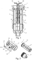
- An inventive fluid filter 1 which is designed as a urea solution filter, a formed by a pot 3 and a cover 2 filter housing 4, in which a radially from the inside to the outside flowed through ring filter element 5 is arranged.
- the ring filter element 5 separates an internal raw space 6 from an outer clean room 7, wherein the ring filter element 5 also has a lower end disk 8 and an upper end disk 9.
- a heating device 10 is provided, which allows heating of the fluid to be filtered, in particular of the urea solution to be heated.
- a receptacle 11 is now provided on the filter housing 4, in particular on the pot 3, into which the heating device 10 can be inserted, this receptacle 11 fluidically separating the heating device 10 from the fluid to be heated, that is, from the urea solution to be heated that the heating device 10 has no direct contact with the fluid. Since the urea solution, in particular when heated, has a highly corrosive effect, a corrosion process on the heating device 10 can be reliably prevented with the receptacle 11 provided according to the invention, since the heating device 10 is not in direct contact with the urea solution at any time. Under urea solution is understood to be an approximately 32.5% aqueous solution of urea (H 4 N 2 O).
- the filter housing 4 and in particular the cover 2 and the pot 3 may be formed of plastic, wherein the receptacle 11 to the filter housing 4, that is, in particular to the pot 3 thereof may be formed.
- the pot 3 of the filter housing 4 is preferably fixedly mounted in the vehicle. At the pot is 3 In this case, both an inlet channel 12 and an outlet channel 13 are arranged, wherein the outlet channel 13 is arranged on a lateral surface of the pot 3 or alternatively on the cover 2.
- a circumferentially extending and radially inwardly directed depth stop 14 can be formed on the filter housing 4, to the one hand, the ring filter element 5 tightly applies its end plate 9 and thereby the crude space 6 separates from the clean room 7 and on the other hand, a too deep insertion of the ring filter element 5 in the filter housing 4 is reliably prevented.
- the ring filter element 5 abuts with an end face of its upper end disk 9 on the depth stop 14.
- an O-ring seal 15 may be provided which seals the end plate 9 with respect to a lateral surface of the pot 3 and thereby also ensures a reliable separation of the raw space 6 from the clean room 7.
- the O-ring seal 15 is preferably received in a groove of the upper end plate 9.
- other forms of sealing between the ring filter element 5 and pot 3 of the filter housing 4, such as, for example, a sealing lip surrounding the upper end disk 9 or a molded seal molded onto the upper end disk 9 may be provided.
- Fig. 1 is outlined with the arrows, the way the urea solution through the filter device 1.
- the urea solution pumped out of the urea solution tank passes into the filter device 1.
- the urea solution then flows around the receptacle 11, which is located inside the ring filter element 5. Then, the urea solution passes through the filter medium and leaves the filter device 1 via the outlet 13 again.
- the pocket-like receptacle 11 may be formed such that it is open from the outside, so that the heater 10 from outside the filter housing 4 in the receptacle 11 can be inserted. How the particular Fig. 1 can be seen, it extends the receptacle 11 into an interior of the ring filter element 5 and is thus arranged to save space.
- the heating device 10 can be connected to the receptacle 11 or to the pot 3 of the filter housing 4 of the fluid filter 1 via a latching connection, a clamping connection, a screw connection, a welded connection, a bayonet connection or a clip connection.
- the heater 10 is sealed to the filter housing 4. However, if one wishes to be able to replace the heater 10, a detachable connection of the heater 10 to the filter housing is necessary.
- the heating device 10 is composed of the receptacle 11 into which the respectively selected configuration is inserted and the inserted configuration, i. the receptacle 11 can be removed together with the heater 10 from the filter housing 4 or individually.
- the heating device 10 itself can be traversed by a warming fluid as required in the Figures 1 and 2 illustrated or alternatively have electrical heating elements (not shown).
- a warming fluid for example, warm cooling water coming from the engine
- the heating device 10 has a supply port 20 and an outlet connection 21.
- the heater 10 further comprises a means 22 for flow guidance.
- This flow-directing means 22 can, as in Fig. 2 shown to be sword-like, but it can also have any other arbitrary shape. In the example shown are still guides for insertion of the flow control means 22 on the outer wall of the receptacle 11 is provided.
- electrical heating elements can also be provided in the heating device 10. It should be ensured in this case that the heating elements lie close to the wall of the receptacle 11 in order to achieve the best possible heat transfer through the wall to the urea solution located in the filter housing 4.
- the heating elements and their electrical leads can be integrated in the wall of the receptacle 11. It may also be small attachment means mounted on the side facing away from the fluid of the wall, in which the heating elements are inserted.
- the recording 11 can be like in Fig. 1
- the cover 2 of the filter housing 4 can for maintenance a drain plug for discharging the fluid contained in the filter housing 4, for example, the urea solution, have shown approximately two-thirds of the ring filter element 5 penetrate, or more or less, depending on the requirements of the filter device.
- the fluid is then drained off via the drain plug and then the filter element 5 is removed with the cover 2 of the filter housing.
- the lower, closed end disk 8 latching means which cooperate with counter-locking means in the lid 2.
- the fluid located in the filter housing 4 can be particularly effective and fast be heated, since there are only small liquid spaces in which the fluid can freeze.
- the fluid filter 1 in particular its life can be significantly extended and thus increase the reliability, since a direct contact between the heater 10 and the fluid to be filtered, that is, the urea solution to be filtered, can be reliably excluded by the inventively provided recording 11. As a result, in particular the corrosion processes on the heating device 10 which shorten the service life can be avoided.
Landscapes
- Engineering & Computer Science (AREA)
- Chemical & Material Sciences (AREA)
- Combustion & Propulsion (AREA)
- Mechanical Engineering (AREA)
- General Engineering & Computer Science (AREA)
- Chemical Kinetics & Catalysis (AREA)
- Exhaust Gas After Treatment (AREA)
Applications Claiming Priority (2)
| Application Number | Priority Date | Filing Date | Title |
|---|---|---|---|
| DE102010033682A DE102010033682A1 (de) | 2010-08-06 | 2010-08-06 | Fluidfilter |
| PCT/EP2011/062709 WO2012016871A1 (de) | 2010-08-06 | 2011-07-25 | Fluidfilter |
Publications (3)
| Publication Number | Publication Date |
|---|---|
| EP2600962A1 EP2600962A1 (de) | 2013-06-12 |
| EP2600962B1 EP2600962B1 (de) | 2016-05-11 |
| EP2600962B2 true EP2600962B2 (de) | 2019-03-20 |
Family
ID=44503800
Family Applications (1)
| Application Number | Title | Priority Date | Filing Date |
|---|---|---|---|
| EP11738692.0A Not-in-force EP2600962B2 (de) | 2010-08-06 | 2011-07-25 | Fluidfilter |
Country Status (5)
| Country | Link |
|---|---|
| US (1) | US20130199979A1 (pl) |
| EP (1) | EP2600962B2 (pl) |
| DE (1) | DE102010033682A1 (pl) |
| PL (1) | PL2600962T3 (pl) |
| WO (1) | WO2012016871A1 (pl) |
Families Citing this family (12)
| Publication number | Priority date | Publication date | Assignee | Title |
|---|---|---|---|---|
| US9468875B2 (en) | 2014-01-14 | 2016-10-18 | Caterpillar Inc. | Filter system and filtration method for fluid reservoirs |
| US9248390B2 (en) | 2014-01-14 | 2016-02-02 | Caterpillar Inc. | Filter system and filtration method for fluid reservoirs |
| DE102014216385A1 (de) | 2014-08-19 | 2016-02-25 | Mahle International Gmbh | Fluidfilter |
| US10245534B2 (en) * | 2015-05-28 | 2019-04-02 | Shaw Development, Llc | Filter inline heater |
| CN107228037B (zh) * | 2016-03-23 | 2020-10-27 | 上海欧菲滤清器有限公司 | 燃油滤清器 |
| US10100697B2 (en) | 2016-04-11 | 2018-10-16 | Tenneco Automotive Operating Company Inc. | Fluid delivery system for exhaust aftertreatment system |
| CN207470267U (zh) * | 2017-02-08 | 2018-06-08 | 天纳克(苏州)排放系统有限公司 | 尿素加热过滤系统以及后处理系统组件 |
| CN108397264A (zh) * | 2017-02-08 | 2018-08-14 | 天纳克(苏州)排放系统有限公司 | 加热过滤组件以及后处理系统组件 |
| JP7270367B2 (ja) * | 2018-12-04 | 2023-05-10 | ヤマシンフィルタ株式会社 | フィルタ装置 |
| CN110302581A (zh) * | 2019-07-26 | 2019-10-08 | 潍坊派克汉尼汾过滤系统有限公司 | 一种尿素滤清器 |
| DE102020214869B4 (de) | 2020-11-26 | 2024-11-07 | Vitesco Technologies GmbH | Fördervorrichtung mit Filterelement |
| CN114483262B (zh) * | 2021-12-29 | 2023-05-23 | 潍柴动力股份有限公司 | 尿素泵、尿素泵的控制方法及控制系统 |
Family Cites Families (39)
| Publication number | Priority date | Publication date | Assignee | Title |
|---|---|---|---|---|
| BE458247A (pl) | 1944-02-26 | |||
| US2529698A (en) * | 1946-07-13 | 1950-11-14 | Earl T Julius | Filter apparatus |
| US2635759A (en) | 1950-01-26 | 1953-04-21 | William C Schwalge | Oil reclaimer for internal-combustion engines |
| US3235084A (en) * | 1962-01-30 | 1966-02-15 | Stewart Warner Corp | Fuel filter with heating unit |
| GB1270665A (en) | 1968-08-30 | 1972-04-12 | Plough Contracts Ltd | Improvements in or relating to liquid separators |
| US4059520A (en) | 1976-06-01 | 1977-11-22 | Eastman Kodak Company | Apparatus for filtering and heating a liquid |
| FR2487432A1 (fr) * | 1980-07-24 | 1982-01-29 | Diry Andre | Filtre pour le filtrage et le rechauffage simultanes du carburant |
| JPS5896161A (ja) | 1981-12-04 | 1983-06-08 | Tokyo Roki Kk | エンジンの燃料加熱装置 |
| US4476028A (en) | 1983-04-25 | 1984-10-09 | Stant Inc. | Heater and water probe |
| FR2549148B1 (fr) | 1983-07-13 | 1987-08-21 | Diry Andre | Dispositif combine pour le chauffage et le filtration d'un combustible liquide tel que du gazole |
| US4585924A (en) * | 1983-08-08 | 1986-04-29 | Ford Motor Company | Self-contained electric diesel engine fuel filter assembly heater |
| US4580542A (en) * | 1984-02-14 | 1986-04-08 | Aisin Seiki Kabushiki Kaisha | Fuel heater and fuel contamination detecting apparatus |
| DE3514053A1 (de) * | 1985-04-18 | 1986-10-23 | Lacrex Brevetti S.A., Orselina | Vorrichtung zum vorwaermen von fluessigkeiten, insbesondere von fluessigen brenn- oder kraftstoffen |
| IT1182747B (it) * | 1985-06-10 | 1987-10-05 | Ital Idee Srl | Dispositivo di alimentazione di combustibile, particolarmente per motori a ciclo diesel, con organi di filtraggio, riscaldamento ed emulsionamento del combustibile stesso |
| DE3741281A1 (de) | 1987-08-29 | 1989-03-09 | Fritz Dipl Ing Mueller | Dieselheizer |
| DE3832679A1 (de) * | 1988-09-27 | 1990-03-29 | Boll & Kirch Filter | Rueckspuelfilter |
| US5084170A (en) | 1989-09-08 | 1992-01-28 | Stanadyne Automotive Corp. | Fuel filter |
| DE4118417A1 (de) * | 1990-06-15 | 1992-01-09 | Josef Wittmann | Vorrichtung zum vorwaermen von dieselkraftstoffen |
| US5378358A (en) * | 1993-05-10 | 1995-01-03 | Park; Robert | Fuel processing unit |
| US5443053A (en) * | 1993-07-27 | 1995-08-22 | Johnson; Jack E. | Fuel heater |
| EP1036930B1 (de) * | 1999-03-18 | 2004-09-22 | David + Baader DBK Spezialfabrik Elektrischer Apparate und Heizwiderstände GmbH | Heizeinrichtung für Dieselkraftstoff und beheiztes Dieselfiltersystem |
| ITRE20020022A1 (it) | 2002-03-08 | 2003-09-08 | Ufi Universal Filter Int Spa | Filtro per carburante con dispositivo di autoriscaldamento |
| ITRE20030090A1 (it) | 2003-09-29 | 2005-03-30 | Ufi Filters Spa | Filtro per gasolio |
| ITRE20030024U1 (it) | 2003-10-31 | 2005-05-01 | Ufi Filters Spa | Filtro carburante con dispositivo riscaldatore |
| US6974537B2 (en) * | 2003-11-19 | 2005-12-13 | Ali Hasan Hamdan Abdelqader | Diesel fuel purifier |
| ITRE20040066A1 (it) * | 2004-06-01 | 2004-09-01 | Ufi Filters Spa | Gruppo filtrante perfezionato per motori endotermici a gasolio |
| JP3756921B1 (ja) * | 2004-10-18 | 2006-03-22 | 日産ディーゼル工業株式会社 | 還元剤容器の構造 |
| DE102005011182A1 (de) * | 2005-03-09 | 2006-09-14 | Mann + Hummel Gmbh | Heizeinrichtung für Kraftstoffe |
| DE102005026292A1 (de) | 2005-06-08 | 2006-12-14 | Robert Bosch Gmbh | Filtereinrichtung mit einem Filterelement |
| DE102005037201A1 (de) * | 2005-08-06 | 2007-02-22 | Eichenauer Heizelemente Gmbh & Co. Kg | Heizsystem |
| DE102006034077A1 (de) * | 2005-08-16 | 2007-02-22 | Robert Bosch Gmbh | Filtereinrichtung mit einer Heizung |
| ITRE20050139A1 (it) * | 2005-12-13 | 2007-06-14 | Ufi Filters Spa | Filtro per carburante diesel con riscaldatore |
| DE202006007960U1 (de) * | 2006-05-18 | 2006-08-17 | Infiltec Gmbh | Filter für die Ölfiltration |
| DE102007005771B4 (de) * | 2007-02-06 | 2017-07-06 | Robert Bosch Gmbh | Filtereinrichtung, insbesondere Flüssigkeitsfilter, mit einer Heizung |
| DE102007010503B4 (de) * | 2007-03-05 | 2017-12-07 | Robert Bosch Gmbh | Bauteil für einen Flüssigkeitsfilter und Flüssigkeitsfilter |
| US8496816B2 (en) * | 2007-09-24 | 2013-07-30 | Cummins Filtration Ip, Inc. | Modular fuel filter assembly |
| DE202008016623U1 (de) * | 2008-12-17 | 2010-04-29 | Mann+Hummel Gmbh | Filtereinrichtung für Fluide mit einer elektrischen Heizung |
| EP2236185B1 (en) | 2009-04-03 | 2012-01-04 | Delphi Technologies Holding S.à.r.l. | Filter Assembly |
| DE102009016601B4 (de) * | 2009-04-08 | 2025-07-17 | Mann+Hummel Gmbh | Filtereinrichtung für Fluide, insbesondere für Kraftstoffe |
-
2010
- 2010-08-06 DE DE102010033682A patent/DE102010033682A1/de not_active Withdrawn
-
2011
- 2011-07-25 US US13/814,452 patent/US20130199979A1/en not_active Abandoned
- 2011-07-25 PL PL11738692.0T patent/PL2600962T3/pl unknown
- 2011-07-25 WO PCT/EP2011/062709 patent/WO2012016871A1/de not_active Ceased
- 2011-07-25 EP EP11738692.0A patent/EP2600962B2/de not_active Not-in-force
Also Published As
| Publication number | Publication date |
|---|---|
| EP2600962A1 (de) | 2013-06-12 |
| US20130199979A1 (en) | 2013-08-08 |
| EP2600962B1 (de) | 2016-05-11 |
| WO2012016871A1 (de) | 2012-02-09 |
| DE102010033682A1 (de) | 2012-02-09 |
| PL2600962T3 (pl) | 2016-12-30 |
Similar Documents
| Publication | Publication Date | Title |
|---|---|---|
| EP2600962B2 (de) | Fluidfilter | |
| DE102010004614B4 (de) | Vorrichtung zur Bereitstellung von flüssigem Reduktionsmittel | |
| EP1766207B1 (de) | Öl-kühlmittel-modul mit kühllmittelpflegesystem | |
| EP2295886B1 (de) | Vorrichtung zum Erwärmen von Flüssigkeiten | |
| EP3011153B2 (de) | Vorratstank mit heizvorrichtung | |
| DE102009050696A1 (de) | Wärmetauscher mit Umgehungsventil | |
| EP2171250B1 (de) | Filterelement und kraftstofffilter | |
| DE102009058159B4 (de) | Filtereinrichtung für Fluide mit einer elektrischen Heizung und Heizung für eine Filtereinrichtung | |
| DE102008052918A1 (de) | Heizeinrichtung für Kraftstoff | |
| EP2514958B1 (de) | Kraftstofffilter für eine Brennkraftmaschine | |
| DE102014010389A1 (de) | Filter für Flüssigkeit mit wenigstens einer Heizeinrichtung und Verfahren zur Herstellung eines Filters | |
| DE3522024C2 (de) | Kraftstoffheizvorrichtung | |
| WO2006094996A1 (de) | Flüssigkeitsfilter-wärmetauscher-einheit | |
| EP3036423B1 (de) | Fluidsystem mit wenigstens einer heizvorrichtung für fluid und heizvorrichtung | |
| DE102012007762A1 (de) | Ölfilter einer Brennkraftmaschine und Ölfilterelement eines Ölfilters | |
| DE102016003521A1 (de) | Filterelement eines Filters, Filter und Fluidsystem mit wenigstens einem Filterelement | |
| DE102012212782A1 (de) | Filtereinrichtung mit einem Partikelfilter | |
| DE202005014632U1 (de) | Wärmetauscher mit Zwischenbauteil und Parallelventil | |
| DE102014015613A1 (de) | Hohlfilterelement und Filter mit einem Hohlfilterelement | |
| DE102010033742A1 (de) | Fluidfilter | |
| DE102019215060B3 (de) | Flüssigkeitsfilter und Tankfiltersystem mit einem Flüssigkeitsfilter | |
| DE102007049582B4 (de) | Vorrichtung zum Anschluß eines Dieselmotors an zwei Tanks | |
| DE102014216385A1 (de) | Fluidfilter | |
| DE102013013309A1 (de) | Behältnis für Fluid mit einer Heizeinrichtung | |
| DE102014008249A1 (de) | Öl-Kühlmittel-Modul, insbesondere für eine Verbrennungskraftmaschine |
Legal Events
| Date | Code | Title | Description |
|---|---|---|---|
| PUAI | Public reference made under article 153(3) epc to a published international application that has entered the european phase |
Free format text: ORIGINAL CODE: 0009012 |
|
| 17P | Request for examination filed |
Effective date: 20130116 |
|
| AK | Designated contracting states |
Kind code of ref document: A1 Designated state(s): AL AT BE BG CH CY CZ DE DK EE ES FI FR GB GR HR HU IE IS IT LI LT LU LV MC MK MT NL NO PL PT RO RS SE SI SK SM TR |
|
| DAX | Request for extension of the european patent (deleted) | ||
| GRAP | Despatch of communication of intention to grant a patent |
Free format text: ORIGINAL CODE: EPIDOSNIGR1 |
|
| RIC1 | Information provided on ipc code assigned before grant |
Ipc: B01D 35/18 20060101AFI20160107BHEP Ipc: F02M 37/22 20060101ALI20160107BHEP |
|
| INTG | Intention to grant announced |
Effective date: 20160119 |
|
| GRAS | Grant fee paid |
Free format text: ORIGINAL CODE: EPIDOSNIGR3 |
|
| GRAA | (expected) grant |
Free format text: ORIGINAL CODE: 0009210 |
|
| AK | Designated contracting states |
Kind code of ref document: B1 Designated state(s): AL AT BE BG CH CY CZ DE DK EE ES FI FR GB GR HR HU IE IS IT LI LT LU LV MC MK MT NL NO PL PT RO RS SE SI SK SM TR |
|
| REG | Reference to a national code |
Ref country code: GB Ref legal event code: FG4D Free format text: NOT ENGLISH |
|
| REG | Reference to a national code |
Ref country code: CH Ref legal event code: EP |
|
| REG | Reference to a national code |
Ref country code: AT Ref legal event code: REF Ref document number: 798186 Country of ref document: AT Kind code of ref document: T Effective date: 20160515 |
|
| REG | Reference to a national code |
Ref country code: IE Ref legal event code: FG4D Free format text: LANGUAGE OF EP DOCUMENT: GERMAN |
|
| REG | Reference to a national code |
Ref country code: DE Ref legal event code: R096 Ref document number: 502011009743 Country of ref document: DE |
|
| REG | Reference to a national code |
Ref country code: FR Ref legal event code: PLFP Year of fee payment: 6 |
|
| REG | Reference to a national code |
Ref country code: LT Ref legal event code: MG4D |
|
| REG | Reference to a national code |
Ref country code: NL Ref legal event code: MP Effective date: 20160511 |
|
| PG25 | Lapsed in a contracting state [announced via postgrant information from national office to epo] |
Ref country code: NL Free format text: LAPSE BECAUSE OF FAILURE TO SUBMIT A TRANSLATION OF THE DESCRIPTION OR TO PAY THE FEE WITHIN THE PRESCRIBED TIME-LIMIT Effective date: 20160511 Ref country code: FI Free format text: LAPSE BECAUSE OF FAILURE TO SUBMIT A TRANSLATION OF THE DESCRIPTION OR TO PAY THE FEE WITHIN THE PRESCRIBED TIME-LIMIT Effective date: 20160511 Ref country code: NO Free format text: LAPSE BECAUSE OF FAILURE TO SUBMIT A TRANSLATION OF THE DESCRIPTION OR TO PAY THE FEE WITHIN THE PRESCRIBED TIME-LIMIT Effective date: 20160811 Ref country code: LT Free format text: LAPSE BECAUSE OF FAILURE TO SUBMIT A TRANSLATION OF THE DESCRIPTION OR TO PAY THE FEE WITHIN THE PRESCRIBED TIME-LIMIT Effective date: 20160511 |
|
| PG25 | Lapsed in a contracting state [announced via postgrant information from national office to epo] |
Ref country code: SE Free format text: LAPSE BECAUSE OF FAILURE TO SUBMIT A TRANSLATION OF THE DESCRIPTION OR TO PAY THE FEE WITHIN THE PRESCRIBED TIME-LIMIT Effective date: 20160511 Ref country code: PT Free format text: LAPSE BECAUSE OF FAILURE TO SUBMIT A TRANSLATION OF THE DESCRIPTION OR TO PAY THE FEE WITHIN THE PRESCRIBED TIME-LIMIT Effective date: 20160912 Ref country code: HR Free format text: LAPSE BECAUSE OF FAILURE TO SUBMIT A TRANSLATION OF THE DESCRIPTION OR TO PAY THE FEE WITHIN THE PRESCRIBED TIME-LIMIT Effective date: 20160511 Ref country code: ES Free format text: LAPSE BECAUSE OF FAILURE TO SUBMIT A TRANSLATION OF THE DESCRIPTION OR TO PAY THE FEE WITHIN THE PRESCRIBED TIME-LIMIT Effective date: 20160511 Ref country code: RS Free format text: LAPSE BECAUSE OF FAILURE TO SUBMIT A TRANSLATION OF THE DESCRIPTION OR TO PAY THE FEE WITHIN THE PRESCRIBED TIME-LIMIT Effective date: 20160511 Ref country code: LV Free format text: LAPSE BECAUSE OF FAILURE TO SUBMIT A TRANSLATION OF THE DESCRIPTION OR TO PAY THE FEE WITHIN THE PRESCRIBED TIME-LIMIT Effective date: 20160511 Ref country code: GR Free format text: LAPSE BECAUSE OF FAILURE TO SUBMIT A TRANSLATION OF THE DESCRIPTION OR TO PAY THE FEE WITHIN THE PRESCRIBED TIME-LIMIT Effective date: 20160812 |
|
| PG25 | Lapsed in a contracting state [announced via postgrant information from national office to epo] |
Ref country code: BE Free format text: LAPSE BECAUSE OF NON-PAYMENT OF DUE FEES Effective date: 20160731 |
|
| PG25 | Lapsed in a contracting state [announced via postgrant information from national office to epo] |
Ref country code: EE Free format text: LAPSE BECAUSE OF FAILURE TO SUBMIT A TRANSLATION OF THE DESCRIPTION OR TO PAY THE FEE WITHIN THE PRESCRIBED TIME-LIMIT Effective date: 20160511 Ref country code: DK Free format text: LAPSE BECAUSE OF FAILURE TO SUBMIT A TRANSLATION OF THE DESCRIPTION OR TO PAY THE FEE WITHIN THE PRESCRIBED TIME-LIMIT Effective date: 20160511 Ref country code: CZ Free format text: LAPSE BECAUSE OF FAILURE TO SUBMIT A TRANSLATION OF THE DESCRIPTION OR TO PAY THE FEE WITHIN THE PRESCRIBED TIME-LIMIT Effective date: 20160511 Ref country code: SK Free format text: LAPSE BECAUSE OF FAILURE TO SUBMIT A TRANSLATION OF THE DESCRIPTION OR TO PAY THE FEE WITHIN THE PRESCRIBED TIME-LIMIT Effective date: 20160511 Ref country code: RO Free format text: LAPSE BECAUSE OF FAILURE TO SUBMIT A TRANSLATION OF THE DESCRIPTION OR TO PAY THE FEE WITHIN THE PRESCRIBED TIME-LIMIT Effective date: 20160511 |
|
| REG | Reference to a national code |
Ref country code: DE Ref legal event code: R026 Ref document number: 502011009743 Country of ref document: DE |
|
| PLBI | Opposition filed |
Free format text: ORIGINAL CODE: 0009260 |
|
| PG25 | Lapsed in a contracting state [announced via postgrant information from national office to epo] |
Ref country code: SM Free format text: LAPSE BECAUSE OF FAILURE TO SUBMIT A TRANSLATION OF THE DESCRIPTION OR TO PAY THE FEE WITHIN THE PRESCRIBED TIME-LIMIT Effective date: 20160511 |
|
| REG | Reference to a national code |
Ref country code: CH Ref legal event code: PL |
|
| PLAX | Notice of opposition and request to file observation + time limit sent |
Free format text: ORIGINAL CODE: EPIDOSNOBS2 |
|
| 26 | Opposition filed |
Opponent name: MANN + HUMMEL GMBH Effective date: 20170208 |
|
| PG25 | Lapsed in a contracting state [announced via postgrant information from national office to epo] |
Ref country code: MC Free format text: LAPSE BECAUSE OF FAILURE TO SUBMIT A TRANSLATION OF THE DESCRIPTION OR TO PAY THE FEE WITHIN THE PRESCRIBED TIME-LIMIT Effective date: 20160511 |
|
| GBPC | Gb: european patent ceased through non-payment of renewal fee |
Effective date: 20160811 |
|
| PG25 | Lapsed in a contracting state [announced via postgrant information from national office to epo] |
Ref country code: CH Free format text: LAPSE BECAUSE OF NON-PAYMENT OF DUE FEES Effective date: 20160731 Ref country code: LI Free format text: LAPSE BECAUSE OF NON-PAYMENT OF DUE FEES Effective date: 20160731 |
|
| REG | Reference to a national code |
Ref country code: IE Ref legal event code: MM4A |
|
| PG25 | Lapsed in a contracting state [announced via postgrant information from national office to epo] |
Ref country code: SI Free format text: LAPSE BECAUSE OF FAILURE TO SUBMIT A TRANSLATION OF THE DESCRIPTION OR TO PAY THE FEE WITHIN THE PRESCRIBED TIME-LIMIT Effective date: 20160511 |
|
| PLBB | Reply of patent proprietor to notice(s) of opposition received |
Free format text: ORIGINAL CODE: EPIDOSNOBS3 |
|
| REG | Reference to a national code |
Ref country code: FR Ref legal event code: PLFP Year of fee payment: 7 |
|
| PG25 | Lapsed in a contracting state [announced via postgrant information from national office to epo] |
Ref country code: GB Free format text: LAPSE BECAUSE OF NON-PAYMENT OF DUE FEES Effective date: 20160811 Ref country code: IE Free format text: LAPSE BECAUSE OF NON-PAYMENT OF DUE FEES Effective date: 20160725 |
|
| PG25 | Lapsed in a contracting state [announced via postgrant information from national office to epo] |
Ref country code: LU Free format text: LAPSE BECAUSE OF NON-PAYMENT OF DUE FEES Effective date: 20160725 |
|
| REG | Reference to a national code |
Ref country code: AT Ref legal event code: MM01 Ref document number: 798186 Country of ref document: AT Kind code of ref document: T Effective date: 20160725 |
|
| PG25 | Lapsed in a contracting state [announced via postgrant information from national office to epo] |
Ref country code: AT Free format text: LAPSE BECAUSE OF NON-PAYMENT OF DUE FEES Effective date: 20160725 |
|
| PG25 | Lapsed in a contracting state [announced via postgrant information from national office to epo] |
Ref country code: HU Free format text: LAPSE BECAUSE OF FAILURE TO SUBMIT A TRANSLATION OF THE DESCRIPTION OR TO PAY THE FEE WITHIN THE PRESCRIBED TIME-LIMIT; INVALID AB INITIO Effective date: 20110725 Ref country code: CY Free format text: LAPSE BECAUSE OF FAILURE TO SUBMIT A TRANSLATION OF THE DESCRIPTION OR TO PAY THE FEE WITHIN THE PRESCRIBED TIME-LIMIT Effective date: 20160511 |
|
| PG25 | Lapsed in a contracting state [announced via postgrant information from national office to epo] |
Ref country code: TR Free format text: LAPSE BECAUSE OF FAILURE TO SUBMIT A TRANSLATION OF THE DESCRIPTION OR TO PAY THE FEE WITHIN THE PRESCRIBED TIME-LIMIT Effective date: 20160511 Ref country code: MK Free format text: LAPSE BECAUSE OF FAILURE TO SUBMIT A TRANSLATION OF THE DESCRIPTION OR TO PAY THE FEE WITHIN THE PRESCRIBED TIME-LIMIT Effective date: 20160511 Ref country code: IS Free format text: LAPSE BECAUSE OF FAILURE TO SUBMIT A TRANSLATION OF THE DESCRIPTION OR TO PAY THE FEE WITHIN THE PRESCRIBED TIME-LIMIT Effective date: 20160511 Ref country code: MT Free format text: LAPSE BECAUSE OF FAILURE TO SUBMIT A TRANSLATION OF THE DESCRIPTION OR TO PAY THE FEE WITHIN THE PRESCRIBED TIME-LIMIT Effective date: 20160511 |
|
| REG | Reference to a national code |
Ref country code: FR Ref legal event code: PLFP Year of fee payment: 8 |
|
| PG25 | Lapsed in a contracting state [announced via postgrant information from national office to epo] |
Ref country code: BG Free format text: LAPSE BECAUSE OF FAILURE TO SUBMIT A TRANSLATION OF THE DESCRIPTION OR TO PAY THE FEE WITHIN THE PRESCRIBED TIME-LIMIT Effective date: 20160511 |
|
| PG25 | Lapsed in a contracting state [announced via postgrant information from national office to epo] |
Ref country code: AL Free format text: LAPSE BECAUSE OF FAILURE TO SUBMIT A TRANSLATION OF THE DESCRIPTION OR TO PAY THE FEE WITHIN THE PRESCRIBED TIME-LIMIT Effective date: 20160511 |
|
| PGFP | Annual fee paid to national office [announced via postgrant information from national office to epo] |
Ref country code: IT Payment date: 20180723 Year of fee payment: 8 Ref country code: FR Payment date: 20180726 Year of fee payment: 8 |
|
| PGFP | Annual fee paid to national office [announced via postgrant information from national office to epo] |
Ref country code: PL Payment date: 20180713 Year of fee payment: 8 |
|
| PGFP | Annual fee paid to national office [announced via postgrant information from national office to epo] |
Ref country code: DE Payment date: 20180928 Year of fee payment: 8 |
|
| PUAH | Patent maintained in amended form |
Free format text: ORIGINAL CODE: 0009272 |
|
| STAA | Information on the status of an ep patent application or granted ep patent |
Free format text: STATUS: PATENT MAINTAINED AS AMENDED |
|
| 27A | Patent maintained in amended form |
Effective date: 20190320 |
|
| AK | Designated contracting states |
Kind code of ref document: B2 Designated state(s): AL AT BE BG CH CY CZ DE DK EE ES FI FR GB GR HR HU IE IS IT LI LT LU LV MC MK MT NL NO PL PT RO RS SE SI SK SM TR |
|
| REG | Reference to a national code |
Ref country code: DE Ref legal event code: R102 Ref document number: 502011009743 Country of ref document: DE |
|
| REG | Reference to a national code |
Ref country code: DE Ref legal event code: R119 Ref document number: 502011009743 Country of ref document: DE |
|
| PG25 | Lapsed in a contracting state [announced via postgrant information from national office to epo] |
Ref country code: DE Free format text: LAPSE BECAUSE OF NON-PAYMENT OF DUE FEES Effective date: 20200201 |
|
| PG25 | Lapsed in a contracting state [announced via postgrant information from national office to epo] |
Ref country code: FR Free format text: LAPSE BECAUSE OF NON-PAYMENT OF DUE FEES Effective date: 20190731 |
|
| PG25 | Lapsed in a contracting state [announced via postgrant information from national office to epo] |
Ref country code: IT Free format text: LAPSE BECAUSE OF NON-PAYMENT OF DUE FEES Effective date: 20190725 |
|
| PG25 | Lapsed in a contracting state [announced via postgrant information from national office to epo] |
Ref country code: PL Free format text: THE PATENT HAS BEEN ANNULLED BY A DECISION OF A NATIONAL AUTHORITY Effective date: 20190620 |
|
| PG25 | Lapsed in a contracting state [announced via postgrant information from national office to epo] |
Ref country code: PL Free format text: THE PATENT HAS BEEN ANNULLED BY A DECISION OF A NATIONAL AUTHORITY Effective date: 20190620 |