EP2600022A1 - Leerlaufsteuerungsvorrichtung - Google Patents
Leerlaufsteuerungsvorrichtung Download PDFInfo
- Publication number
- EP2600022A1 EP2600022A1 EP11812244.9A EP11812244A EP2600022A1 EP 2600022 A1 EP2600022 A1 EP 2600022A1 EP 11812244 A EP11812244 A EP 11812244A EP 2600022 A1 EP2600022 A1 EP 2600022A1
- Authority
- EP
- European Patent Office
- Prior art keywords
- coasting control
- turning
- clutch
- vehicle
- engine
- Prior art date
- Legal status (The legal status is an assumption and is not a legal conclusion. Google has not performed a legal analysis and makes no representation as to the accuracy of the status listed.)
- Granted
Links
- 230000007423 decrease Effects 0.000 claims description 9
- 101100400452 Caenorhabditis elegans map-2 gene Proteins 0.000 description 19
- 239000000446 fuel Substances 0.000 description 17
- 230000001133 acceleration Effects 0.000 description 8
- 238000010586 diagram Methods 0.000 description 6
- 230000005540 biological transmission Effects 0.000 description 5
- 230000000694 effects Effects 0.000 description 5
- 239000011248 coating agent Substances 0.000 description 4
- 238000000576 coating method Methods 0.000 description 4
- 230000006641 stabilisation Effects 0.000 description 3
- 238000011105 stabilization Methods 0.000 description 3
- 230000006399 behavior Effects 0.000 description 2
- 238000005266 casting Methods 0.000 description 1
- 238000012508 change request Methods 0.000 description 1
- 238000002474 experimental method Methods 0.000 description 1
- 238000000034 method Methods 0.000 description 1
- 230000007935 neutral effect Effects 0.000 description 1
Images


Classifications
-
- B—PERFORMING OPERATIONS; TRANSPORTING
- B60—VEHICLES IN GENERAL
- B60W—CONJOINT CONTROL OF VEHICLE SUB-UNITS OF DIFFERENT TYPE OR DIFFERENT FUNCTION; CONTROL SYSTEMS SPECIALLY ADAPTED FOR HYBRID VEHICLES; ROAD VEHICLE DRIVE CONTROL SYSTEMS FOR PURPOSES NOT RELATED TO THE CONTROL OF A PARTICULAR SUB-UNIT
- B60W10/00—Conjoint control of vehicle sub-units of different type or different function
- B60W10/02—Conjoint control of vehicle sub-units of different type or different function including control of driveline clutches
-
- B—PERFORMING OPERATIONS; TRANSPORTING
- B60—VEHICLES IN GENERAL
- B60W—CONJOINT CONTROL OF VEHICLE SUB-UNITS OF DIFFERENT TYPE OR DIFFERENT FUNCTION; CONTROL SYSTEMS SPECIALLY ADAPTED FOR HYBRID VEHICLES; ROAD VEHICLE DRIVE CONTROL SYSTEMS FOR PURPOSES NOT RELATED TO THE CONTROL OF A PARTICULAR SUB-UNIT
- B60W30/00—Purposes of road vehicle drive control systems not related to the control of a particular sub-unit, e.g. of systems using conjoint control of vehicle sub-units
- B60W30/18—Propelling the vehicle
- B60W30/18009—Propelling the vehicle related to particular drive situations
- B60W30/18072—Coasting
-
- B—PERFORMING OPERATIONS; TRANSPORTING
- B60—VEHICLES IN GENERAL
- B60W—CONJOINT CONTROL OF VEHICLE SUB-UNITS OF DIFFERENT TYPE OR DIFFERENT FUNCTION; CONTROL SYSTEMS SPECIALLY ADAPTED FOR HYBRID VEHICLES; ROAD VEHICLE DRIVE CONTROL SYSTEMS FOR PURPOSES NOT RELATED TO THE CONTROL OF A PARTICULAR SUB-UNIT
- B60W30/00—Purposes of road vehicle drive control systems not related to the control of a particular sub-unit, e.g. of systems using conjoint control of vehicle sub-units
- B60W30/18—Propelling the vehicle
- B60W30/18009—Propelling the vehicle related to particular drive situations
- B60W30/18145—Cornering
-
- F—MECHANICAL ENGINEERING; LIGHTING; HEATING; WEAPONS; BLASTING
- F16—ENGINEERING ELEMENTS AND UNITS; GENERAL MEASURES FOR PRODUCING AND MAINTAINING EFFECTIVE FUNCTIONING OF MACHINES OR INSTALLATIONS; THERMAL INSULATION IN GENERAL
- F16D—COUPLINGS FOR TRANSMITTING ROTATION; CLUTCHES; BRAKES
- F16D48/00—External control of clutches
- F16D48/06—Control by electric or electronic means, e.g. of fluid pressure
- F16D48/066—Control of fluid pressure, e.g. using an accumulator
-
- B—PERFORMING OPERATIONS; TRANSPORTING
- B60—VEHICLES IN GENERAL
- B60W—CONJOINT CONTROL OF VEHICLE SUB-UNITS OF DIFFERENT TYPE OR DIFFERENT FUNCTION; CONTROL SYSTEMS SPECIALLY ADAPTED FOR HYBRID VEHICLES; ROAD VEHICLE DRIVE CONTROL SYSTEMS FOR PURPOSES NOT RELATED TO THE CONTROL OF A PARTICULAR SUB-UNIT
- B60W2510/00—Input parameters relating to a particular sub-units
- B60W2510/02—Clutches
- B60W2510/0283—Clutch input shaft speed
-
- B—PERFORMING OPERATIONS; TRANSPORTING
- B60—VEHICLES IN GENERAL
- B60W—CONJOINT CONTROL OF VEHICLE SUB-UNITS OF DIFFERENT TYPE OR DIFFERENT FUNCTION; CONTROL SYSTEMS SPECIALLY ADAPTED FOR HYBRID VEHICLES; ROAD VEHICLE DRIVE CONTROL SYSTEMS FOR PURPOSES NOT RELATED TO THE CONTROL OF A PARTICULAR SUB-UNIT
- B60W2520/00—Input parameters relating to overall vehicle dynamics
- B60W2520/06—Direction of travel
-
- B—PERFORMING OPERATIONS; TRANSPORTING
- B60—VEHICLES IN GENERAL
- B60W—CONJOINT CONTROL OF VEHICLE SUB-UNITS OF DIFFERENT TYPE OR DIFFERENT FUNCTION; CONTROL SYSTEMS SPECIALLY ADAPTED FOR HYBRID VEHICLES; ROAD VEHICLE DRIVE CONTROL SYSTEMS FOR PURPOSES NOT RELATED TO THE CONTROL OF A PARTICULAR SUB-UNIT
- B60W2520/00—Input parameters relating to overall vehicle dynamics
- B60W2520/14—Yaw
-
- B—PERFORMING OPERATIONS; TRANSPORTING
- B60—VEHICLES IN GENERAL
- B60W—CONJOINT CONTROL OF VEHICLE SUB-UNITS OF DIFFERENT TYPE OR DIFFERENT FUNCTION; CONTROL SYSTEMS SPECIALLY ADAPTED FOR HYBRID VEHICLES; ROAD VEHICLE DRIVE CONTROL SYSTEMS FOR PURPOSES NOT RELATED TO THE CONTROL OF A PARTICULAR SUB-UNIT
- B60W2520/00—Input parameters relating to overall vehicle dynamics
- B60W2520/28—Wheel speed
-
- B—PERFORMING OPERATIONS; TRANSPORTING
- B60—VEHICLES IN GENERAL
- B60W—CONJOINT CONTROL OF VEHICLE SUB-UNITS OF DIFFERENT TYPE OR DIFFERENT FUNCTION; CONTROL SYSTEMS SPECIALLY ADAPTED FOR HYBRID VEHICLES; ROAD VEHICLE DRIVE CONTROL SYSTEMS FOR PURPOSES NOT RELATED TO THE CONTROL OF A PARTICULAR SUB-UNIT
- B60W2540/00—Input parameters relating to occupants
- B60W2540/10—Accelerator pedal position
- B60W2540/106—Rate of change
-
- B—PERFORMING OPERATIONS; TRANSPORTING
- B60—VEHICLES IN GENERAL
- B60W—CONJOINT CONTROL OF VEHICLE SUB-UNITS OF DIFFERENT TYPE OR DIFFERENT FUNCTION; CONTROL SYSTEMS SPECIALLY ADAPTED FOR HYBRID VEHICLES; ROAD VEHICLE DRIVE CONTROL SYSTEMS FOR PURPOSES NOT RELATED TO THE CONTROL OF A PARTICULAR SUB-UNIT
- B60W2710/00—Output or target parameters relating to a particular sub-units
- B60W2710/06—Combustion engines, Gas turbines
- B60W2710/0644—Engine speed
- B60W2710/0655—Coasting condition
-
- B—PERFORMING OPERATIONS; TRANSPORTING
- B60—VEHICLES IN GENERAL
- B60W—CONJOINT CONTROL OF VEHICLE SUB-UNITS OF DIFFERENT TYPE OR DIFFERENT FUNCTION; CONTROL SYSTEMS SPECIALLY ADAPTED FOR HYBRID VEHICLES; ROAD VEHICLE DRIVE CONTROL SYSTEMS FOR PURPOSES NOT RELATED TO THE CONTROL OF A PARTICULAR SUB-UNIT
- B60W30/00—Purposes of road vehicle drive control systems not related to the control of a particular sub-unit, e.g. of systems using conjoint control of vehicle sub-units
- B60W30/02—Control of vehicle driving stability
-
- B—PERFORMING OPERATIONS; TRANSPORTING
- B60—VEHICLES IN GENERAL
- B60Y—INDEXING SCHEME RELATING TO ASPECTS CROSS-CUTTING VEHICLE TECHNOLOGY
- B60Y2300/00—Purposes or special features of road vehicle drive control systems
- B60Y2300/18—Propelling the vehicle
- B60Y2300/18008—Propelling the vehicle related to particular drive situations
- B60Y2300/18066—Coasting
- B60Y2300/18083—Coasting without torque flow between driveshaft and engine, e.g. with clutch disengaged or transmission in neutral
-
- F—MECHANICAL ENGINEERING; LIGHTING; HEATING; WEAPONS; BLASTING
- F16—ENGINEERING ELEMENTS AND UNITS; GENERAL MEASURES FOR PRODUCING AND MAINTAINING EFFECTIVE FUNCTIONING OF MACHINES OR INSTALLATIONS; THERMAL INSULATION IN GENERAL
- F16D—COUPLINGS FOR TRANSMITTING ROTATION; CLUTCHES; BRAKES
- F16D48/00—External control of clutches
- F16D48/02—Control by fluid pressure
- F16D2048/0227—Source of pressure producing the clutch engagement or disengagement action within a circuit; Means for initiating command action in power assisted devices
- F16D2048/023—Source of pressure producing the clutch engagement or disengagement action within a circuit; Means for initiating command action in power assisted devices by pedal actuation
-
- F—MECHANICAL ENGINEERING; LIGHTING; HEATING; WEAPONS; BLASTING
- F16—ENGINEERING ELEMENTS AND UNITS; GENERAL MEASURES FOR PRODUCING AND MAINTAINING EFFECTIVE FUNCTIONING OF MACHINES OR INSTALLATIONS; THERMAL INSULATION IN GENERAL
- F16D—COUPLINGS FOR TRANSMITTING ROTATION; CLUTCHES; BRAKES
- F16D48/00—External control of clutches
- F16D48/02—Control by fluid pressure
- F16D2048/0227—Source of pressure producing the clutch engagement or disengagement action within a circuit; Means for initiating command action in power assisted devices
- F16D2048/0254—Double actuation, i.e. two actuation means can produce independently an engagement or disengagement of the clutch
-
- F—MECHANICAL ENGINEERING; LIGHTING; HEATING; WEAPONS; BLASTING
- F16—ENGINEERING ELEMENTS AND UNITS; GENERAL MEASURES FOR PRODUCING AND MAINTAINING EFFECTIVE FUNCTIONING OF MACHINES OR INSTALLATIONS; THERMAL INSULATION IN GENERAL
- F16D—COUPLINGS FOR TRANSMITTING ROTATION; CLUTCHES; BRAKES
- F16D2500/00—External control of clutches by electric or electronic means
- F16D2500/50—Problem to be solved by the control system
- F16D2500/508—Relating driving conditions
- F16D2500/5085—Coasting
-
- F—MECHANICAL ENGINEERING; LIGHTING; HEATING; WEAPONS; BLASTING
- F16—ENGINEERING ELEMENTS AND UNITS; GENERAL MEASURES FOR PRODUCING AND MAINTAINING EFFECTIVE FUNCTIONING OF MACHINES OR INSTALLATIONS; THERMAL INSULATION IN GENERAL
- F16D—COUPLINGS FOR TRANSMITTING ROTATION; CLUTCHES; BRAKES
- F16D2500/00—External control of clutches by electric or electronic means
- F16D2500/50—Problem to be solved by the control system
- F16D2500/51—Relating safety
-
- F—MECHANICAL ENGINEERING; LIGHTING; HEATING; WEAPONS; BLASTING
- F16—ENGINEERING ELEMENTS AND UNITS; GENERAL MEASURES FOR PRODUCING AND MAINTAINING EFFECTIVE FUNCTIONING OF MACHINES OR INSTALLATIONS; THERMAL INSULATION IN GENERAL
- F16D—COUPLINGS FOR TRANSMITTING ROTATION; CLUTCHES; BRAKES
- F16D2500/00—External control of clutches by electric or electronic means
- F16D2500/70—Details about the implementation of the control system
- F16D2500/704—Output parameters from the control unit; Target parameters to be controlled
- F16D2500/70422—Clutch parameters
- F16D2500/70424—Outputting a clutch engaged-disengaged signal
-
- F—MECHANICAL ENGINEERING; LIGHTING; HEATING; WEAPONS; BLASTING
- F16—ENGINEERING ELEMENTS AND UNITS; GENERAL MEASURES FOR PRODUCING AND MAINTAINING EFFECTIVE FUNCTIONING OF MACHINES OR INSTALLATIONS; THERMAL INSULATION IN GENERAL
- F16D—COUPLINGS FOR TRANSMITTING ROTATION; CLUTCHES; BRAKES
- F16D2500/00—External control of clutches by electric or electronic means
- F16D2500/70—Details about the implementation of the control system
- F16D2500/71—Actions
- F16D2500/7105—Inhibit control automatically
-
- Y—GENERAL TAGGING OF NEW TECHNOLOGICAL DEVELOPMENTS; GENERAL TAGGING OF CROSS-SECTIONAL TECHNOLOGIES SPANNING OVER SEVERAL SECTIONS OF THE IPC; TECHNICAL SUBJECTS COVERED BY FORMER USPC CROSS-REFERENCE ART COLLECTIONS [XRACs] AND DIGESTS
- Y02—TECHNOLOGIES OR APPLICATIONS FOR MITIGATION OR ADAPTATION AGAINST CLIMATE CHANGE
- Y02T—CLIMATE CHANGE MITIGATION TECHNOLOGIES RELATED TO TRANSPORTATION
- Y02T10/00—Road transport of goods or passengers
- Y02T10/60—Other road transportation technologies with climate change mitigation effect
Definitions
- the present invention relates to a coasting control device that suppresses fuel consumption by disengaging a clutch during running and returning an engine to an idle state, and more particularly to a coasting control device capable of avoiding coasting control during turning.
- the accelerator pedal of a vehicle When the accelerator pedal of a vehicle is pressed while the clutch is disengaged, the accelerator is opened to cause the engine to run at "idle" and the engine RPM is stabilized at the engine RPM corresponding to the accelerator opening degree. At that point of time, the driving force generated by the engine and the internal resistance (friction) of the engine are in equilibrium and the engine output torque is 0. That is, the engine does no work for the outside the engine and fuel is wasted. Assuming that the engine runs at idle at the engine RPM of 2000 rpm, a driver can hear loud engine noise and recognize that a considerable amount of fuel is wasted.
- the engine does no work for the outside not only during idling caused by disengagement of the clutch as described above but also while the vehicle is in motion. That is, the engine only revolves at an engine RPM corresponding to the accelerator opening degree as in idling and does not contribute to acceleration or deceleration of the vehicle. At this time, the fuel is consumed only in causing the engine to revolve uselessly, which is highly wasteful.
- the present applicant has proposed a coasting control device that performs coasting control (also referred to as fuel cost running control) that disengages the clutch and places the engine in idle state to save fuel consumption while the engine is running but is doing no work for the outside the engine (Patent Literature 1).
- coasting control also referred to as fuel cost running control
- Roads include curves, each having a constant radius of curvature or a constant change rate of radius of curvature as a junction (ramp) on a highway or the like, on which high-speed running is possible.
- coasting control is not preferable even if conditions are met. That is because, lateral acceleration caused by a centrifugal force, that is, a so-called lateral G acts on a turning vehicle and causes an unstable element for vehicle behaviors, and thus, stabilization control such as ABS (Ant-Lock Braking System) control or the like has been executed. While such delicate vehicle control is being executed, it is necessary to connect the clutch so that the engine driving force or the engine brake can be used for stabilization of the vehicle behaviors.
- ABS Advanced-Lock Braking System
- the present invention has an object to solve the above problem and to provide a coasting control device capable of avoiding coasting control during turning.
- the present invention has been made to achieve the above object and is provided with a coasting control execution unit that disengages a clutch in a driving situation in which the engine does no work for the outside and lowers the engine RPM so as to start coasting control, a turning recognition unit that recognizes that the vehicle is turning, and a unit for prohibiting coasting control during turning that prohibits coasting control when the turning recognition unit recognizes that the vehicle is turning.
- the turning recognition unit may recognize that the vehicle is turning from a difference in rotation speeds between right and left wheels.
- the turning recognition unit may recognize that the vehicle starts turning when the difference in rotation speeds between the right and left wheels exceeds a first threshold value and recognize that the vehicle terminates turning when the difference in rotation speeds between the right and left wheels lowers to a second threshold value, which is smaller than the first threshold value, or less after that.
- the coasting control execution unit may start coasting control by disengaging the clutch and lowering the engine RPM when plotted points of the clutch rotation speed and the accelerator opening degree on the coasting control determination map are within a region capable of coasting control, an accelerator pedal operation speed is within a predetermined range, and plotted points of the clutch rotation speed and the accelerator opening degree pass a coasting control threshold line in a direction where the accelerator opening degree decreases and terminate coasting control when the accelerator pedal opening speed goes out of the predetermined range or the plotted points go out of the region capable of coasting control.
- the present invention exerts the following excellent effect.
- a coasting control device 1 As illustrated in FIG. 1 , a coasting control device 1 according to the present invention is provided with a coasting control execution unit 3 which disengages a clutch in a driving situation in which the engine does no work for the outside and lowers the engine RPM so as to start coasting control, a turning recognition unit 4 which recognizes that a vehicle is turning, and a unit 5 for prohibiting coasting control during turning that prohibits coasting control when the turning recognition unit recognizes that the vehicle is turning.
- a coasting control execution unit 3 which disengages a clutch in a driving situation in which the engine does no work for the outside and lowers the engine RPM so as to start coasting control
- a turning recognition unit 4 which recognizes that a vehicle is turning
- a unit 5 for prohibiting coasting control during turning that prohibits coasting control when the turning recognition unit recognizes that the vehicle is turning.
- the coasting control device 1 is provided with a coasting control determination map 2 to be referred to by a clutch rotation speed and an accelerator opening degree
- the coasting control execution unit 3 starts coasting control by disengaging the clutch and lowering the engine RPM when plotted points of the clutch rotation speed and the accelerator opening degree on the coasting control determination map 2 are within a region capable of coasting control, an accelerator pedal operation speed is within a predetermined range, and plotted points of the clutch rotation speed and the accelerator opening degree pass a coasting control threshold line in a direction where the accelerator opening degree decreases and terminates coasting control when the accelerator pedal opening speed goes out of the predetermined range or the plotted points go out of the region capable of coasting control.
- the turning recognition unit 4 reads information of rotation speeds of right and left wheels from an ABS control unit conventionally mounted on a vehicle and recognizes that the vehicle is turning from a difference in rotation speeds between the right and left wheels.
- a vehicle on which a steering sensor which detects an operation angle of a steering shaft is mounted a vehicle on which a yaw rate sensor which detects a yaw angle of the vehicle is mounted, a vehicle on which a G sensor which detects lateral acceleration of the vehicle is mounted and the like are capable of recognition that the vehicle is turning from these sensor outputs.
- the coasting control determination map 2, the coasting control execution unit 3, the turning recognition unit 4, and the unit 5 for prohibiting coasting control during turning constituting the coasting control device 1 are preferably mounted on an ECU (not shown), for example.
- a clutch system 101 of a vehicle on which the coasting control device 1 of the present invention is mounted is a manual and automatic dual-mode type by means of ECU control.
- a clutch master cylinder 103 mechanically connected to a clutch pedal 102 supplies operation oil to an intermediate cylinder (also referred to as clutch-free operating cylinder and switching cylinder) in accordance with a stepping-in/returning operation of the clutch pedal 102 by a driver.
- a clutch-free actuator unit 105 controlled by the ECU (not shown) supplies operation oil to an intermediate cylinder 104 in accordance with an instruction of clutch engagement/disengagement.
- the intermediate cylinder 104 supplies operation oil to a clutch slave cylinder 106.
- a piston 107 of the clutch slave cylinder 106 is mechanically connected to a movable unit of a clutch 108.
- the actuator 110 is provided with a clutch-free actuator 111.
- the clutch-free actuator 111 is provided with the intermediate cylinder 104 and the clutch-free actuator unit 105.
- the clutch-free actuator unit 105 is provided with a solenoid valve 112, a relief valve 113, and a hydraulic pump 114.
- the intermediate cylinder 104 is composed of a primary piston 116 and a secondary piston 117 arranged in series, and when the primary piston 116 strokes due to the operation oil from the clutch master cylinder 103, the secondary piston 117 is configured to stroke with that.
- the intermediate cylinder 104 is configured such that the secondary piston 117 strokes due to the operation oil form the clutch-free actuator unit 105.
- the coasting control device 1 of the present invention can be applied also to a clutch system only with the automatic type and not having the manual type.
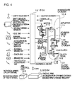
- an ECU 121 which mainly controls a transmission/clutch, an ECM 122 which mainly controls an engine, and an ABS control unit 123.
- input signal lines of a shift knob switch, a shift sensor of the transmission, a select sensor, a neutral switch, a T/M revolution sensor, a vehicle speed sensor, an idle switch, a manual selector switch, a parking brake switch, a door switch, a brake switch, a half-clutch adjustment switch, an accelerator operation amount sensor, a clutch sensor, and an oil pressure switch are connected.
- output signal lines of a motor of the hydraulic pump 114 of the clutch system 101, the solenoid valve 112, a valve for aiding hill start, and warning & meter are connected to the ECM 122.
- various input signal lines and output signal lines used for engine control are connected to the ECM 122.
- the ECM 122 can transmit signals of an engine RPM, an accelerator opening degree, and an engine RPM change request to the ECU 121 through CAN (Controller Area Network) transmission path.
- the ABS control unit 123 can transmit signals of a rotation speed of each of the right and left wheels, a steering shaft operation angle, a yaw angle, and lateral acceleration to the ECU 121 through the CAN transmission path.
- the clutch rotation speed used in the present invention is the number of rotations of clutch on the driven side and is equal to the number of rotations of the input shaft of the transmission.
- the clutch rotation speed can be acquired from the number of input shaft rotations detected by an input shaft rotation number sensor, not shown.
- a clutch rotation speed can be acquired by using a gear ratio of the current gear position from a vehicle speed detected by the vehicle speed sensor.
- the clutch rotation speed indicates the engine RPM corresponding to the vehicle speed.
- the operation principle of coasting control will be described with reference to FIG. 5 .
- the horizontal axis represents time and a flow of control and the vertical axis represents the engine RPM.
- an accelerator pedal 141 is largely pressed down from the idle rotation state and the accelerator opening degree stays at 70%, the engine RPM 142 increases to accelerate the vehicle.
- the engine RPM 142 stabilizes and the amount of depression of the accelerator pedal 141 decreases to reduce the accelerator opening degree to 35%, conditions for starting coasting control, which will be described later, are considered to be satisfied.
- coasting control is started, the clutch is disengaged and the engine RPM 142 is controlled to the idle RPM. The vehicle runs on coasting control.
- coasting control reduces the engine RPM 142 to the idle RPM, thereby saving fuel.
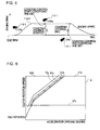
- FIG. 6 illustrates a graph image of the coasting control determination map 2.
- the coasting control determination map 2 is a map with the horizontal axis representing the accelerator opening degree and the vertical axis representing the clutch rotation speed.
- the coasting control determination map 2 can be divided into two regions: a negative region MA where the engine output torque is negative and a positive region PA where the engine output torque is positive.
- the negative region MA is a region where the engine output torque is negative because the friction of the engine is greater than a demanded engine torque.
- the positive region PA is a region where the engine output torque is positive because the demanded engine torque is greater than the friction of the engine.
- the engine output torque zero line ZL which is a boundary between the negative region MA and the positive region PA represents a state in which the engine is doing no work for the outside the engine and fuel is being wasted as described in the Background Art.
- the coasting control threshold line TL is set slightly to the left of the engine output torque zero line ZL (on the side where the accelerator opening degree is small) on the coasting control determination map 2.
- a coasting control available region CA having a finite width including the coasting control threshold line TL is set between the negative region MA and the position region PA on the coasting control determination map 2.
- a clutch rotation speed lower threshold line UL is set on the coasting control determination map 2.
- the lower threshold line UL defines the lower threshold value of the clutch rotation speed independently of the accelerator opening degree. As illustrated, the lower threshold line UL is set slightly above the clutch rotation speed in the idle state.
- the coasting control device 1 starts casting control when all of the following four coasting control start conditions are satisfied.
- the coasting control device 1 ends coasting control when at least one of the following two coasting control end conditions is satisfied.
- the coasting control execution unit 3 monitors the accelerator opening degree on the basis of the accelerator pedal operation amount and the clutch rotation speed acquired from the input shaft rotation number or the vehicle speed all the time and plots coordinate points of the accelerator opening degree and the clutch rotation speed on the coasting control determination map 2 in FIG. 6 .
- the coordinate points move with elapse of time.
- the coasting control execution unit 3 determines whether or not to start coasting control. If the coordinate point is not present in the coasting control available region CA, the coasting control execution unit 3 does not determine whether or not to start coasting control.
- the coasting control execution unit 3 starts coasting control. That is, the coasting control device 1 disengages the clutch and controls the control accelerator opening degree that the ECM 122 instructs to the engine so as to correspond to idling. As a result, the clutch is disengaged, and the engine enters the idle state.
- the direction where the accelerator opening degree decreases is the left direction in illustration. Even if the coordinate point passes the coasting control threshold line TL, if the moving direction of the coordinate point has a component of the right direction in illustration, the accelerator opening degree increases and thus, the coasting control execution unit 3 does not start coasting control.
- the coasting control execution unit 3 monitors the accelerator opening degree and the clutch rotation speed all the time even after the coasting control is started and plots the coordinate points of the accelerator opening degree and the clutch rotation speed on the coasting control determination map 2. If the coordinate point goes out of the coasting control available region CA, the coasting control execution unit 3 ends coasting control.
- the coasting control execution unit 3 does not start coasting control if the coordinate point is present below the lower threshold line UL (the clutch rotation speed is lower than the lower threshold value). That is because even if the clutch is disengaged when the engine is in the idle state, an effect to suppress fuel consumption cannot be expected much. Thus, the coasting control execution unit 3 starts coasting control only when the coordinate point is present above the lower threshold line UL.
- the engine RPM changes within a range of 1600 to 1700 rpm from approximately 30 s to approximately 200 s and lowers from approximately 1700 rpm to approximately 700 rpm (idle RPM) from approximately 200 s to approximately 260 s.
- the engine torque increases from approximately 30 s to approximately 100 s but after that, it changes to decrease and continuously decreases until approximately 150 s.
- the engine torque is substantially 0 Nm from approximately 150 s to approximately 160 s and increases from approximately 160 s to approximately 200 s but becomes substantially 0 Nm at approximately 200 s.
- a period during which the engine torque is substantially 0 Nm occurs at three spots, that is, from approximately 150 s to approximately 160 s (oval B1), from approximately 200 s to approximately 210 s (oval B2), and from approximately 220 s to approximately 260 s (oval B3).
- the fuel consumption amount (no vertical axis scale: arranged so as to overlap with the engine torque for convenience) changes substantially in compliance with the change of the engine torque from approximately 50 s to approximately 200 s. Even if the engine torque is substantially 0 Nm, the fuel consumption amount is not 0.
- the engine rpm is controlled to the idle RPM.
- a line of the engine RPM (bold solid line) during coasting control is indicated as branching from a line of the engine RPM (solid line) when coasting control is not executed.
- the coating control was executed three times at the ovals B1, B2, and B3. The fuel consumption amount during the period when coasting control is executed falls under the fuel consumption amount when coasting control is not executed, and it is known that the fuel consumption is saved.
- the actually measured engine output torque zero line ZL can be drawn.
- the entire left side from the engine output torque zero line ZL is the negative region MA, and the entire right side is the positive region PA.
- the coasting control threshold line TL is defined and drawn slightly to the left of the engine output torque zero line ZL.
- a deceleration zero threshold line TLg is estimated and drawn slightly to the left of the coasting control threshold line TL.
- An acceleration zero threshold line TLk is estimated and drawn slightly to the right of the engine output torque zero line ZL.
- a region sandwiched by the deceleration zero threshold line TLg and the acceleration zero threshold line TLk is defined as the coasting control available region CA.
- the lower threshold line UL is set to 880 rpm in this example.
- the deceleration zero threshold line TLg and the acceleration zero threshold line TLk are set to such a degree that the driver does not drive with difficulty, but since it is a matter of human senses and cannot be digitalized in design, it is tuned on an actual vehicle.
- the coasting control threshold line TL is set at the center between the deceleration zero threshold line TLg and the acceleration zero threshold line TLk.
- the graph in Fig. 8 created as above is digitalized (discretized) as appropriate and written in a storage device, and the coasting control determination map 2 that can be used by the coasting control execution unit 3 for its calculation processing can be obtained.
- the turning recognition unit 4 reads the rotation speeds of the right and left wheels from the ABS control unit 123 and calculates a rotation speed difference ⁇ R. Then, at Step S92, the turning recognition unit 4 determines whether the rotation speed difference ⁇ R exceeds a first threshold value Th1. If YES, since the rotation speed difference ⁇ R between the right and left wheels exceeds the first threshold value Th1, it can be recognized that the vehicle is turning. In this case, the routine proceeds to Step S93. At Step S93, the unit 5 for prohibiting coasting control during turning prohibits coasting control.
- the rotation speed difference ⁇ R is larger than the second threshold value Th2. If this determination is reached in a state where coasting control is allowed, it means that the rotation speed difference ⁇ R becomes the second threshold value Th2 or less once and coating control is allowed and then, becomes larger than the second threshold value Th2, and thus, the routine proceeds to end in order to maintain allowed coasting control. If this determination is reached in a state where coasting control is prohibited, the rotation speed difference ⁇ R exceeds the first threshold value Th1 once and coasting control is prohibited and then, the rotation speed difference ⁇ R does not become the second threshold value Th2 or less yet, and thus, the routine proceeds to end in order to maintain prohibition of coasting control.
- coasting control is prohibited while the vehicle is turning, even if the coasting control start conditions as described in FIG. 6 are satisfied, coasting control is not started. Moreover, even if the vehicle starts turning while coasting control has been already executed, coasting control is prohibited, and even if the coasting control end conditions as described in FIG. 6 are not satisfied, coasting control is terminated.
- the coasting control device 1 of the present invention is configured such that, when it is recognized that the vehicle is turning, the coating control is prohibited, and thus, coasting control does not coincide with or give a bad influence on stabilization control such as ABS control which is important during turning.
- the turning recognition unit 4 can read information of the rotation speeds of the right and left wheels from the ABS control unit 123 and recognize that the vehicle is turning from the difference in the rotation speeds between the right and left wheels.
- the steering sensor, yaw rate sensor, G sensor and the like which can be used for recognition of turning are employed for vehicles of relatively high-order models or so-called luxury vehicles, while the ABS control unit 123 is mounted also on vehicles of low-order models or so-called popular vehicles and thus, the present invention can be applied without adding a new sensor.
- the coasting control device 1 of the present invention recognition of during turning is not made only by comparison between the rotation speed difference ⁇ R between the right and left wheels and one threshold value but if the rotation speed difference ⁇ R between the right and left wheels exceeds the first threshold value Th1, it is recognized that the vehicle is turning and then, if the rotation speed difference between the right and left wheels falls to the second threshold value Th2, smaller than the first threshold value Th1, or less, it is recognized that the vehicle is not turning any more. And thus, so-called hysteresis is realized, and hunting that prohibition and allowing of coasting control are frequently repeated is prevented.
Landscapes
- Engineering & Computer Science (AREA)
- Mechanical Engineering (AREA)
- Transportation (AREA)
- Automation & Control Theory (AREA)
- Physics & Mathematics (AREA)
- Fluid Mechanics (AREA)
- General Engineering & Computer Science (AREA)
- Chemical & Material Sciences (AREA)
- Combustion & Propulsion (AREA)
- Hydraulic Clutches, Magnetic Clutches, Fluid Clutches, And Fluid Joints (AREA)
- Control Of Driving Devices And Active Controlling Of Vehicle (AREA)
- Control Of Vehicle Engines Or Engines For Specific Uses (AREA)
Applications Claiming Priority (2)
| Application Number | Priority Date | Filing Date | Title |
|---|---|---|---|
| JP2010172562A JP5985142B2 (ja) | 2010-07-30 | 2010-07-30 | 惰行制御装置 |
| PCT/JP2011/065565 WO2012014652A1 (ja) | 2010-07-30 | 2011-07-07 | 惰行制御装置 |
Publications (3)
| Publication Number | Publication Date |
|---|---|
| EP2600022A1 true EP2600022A1 (de) | 2013-06-05 |
| EP2600022A4 EP2600022A4 (de) | 2018-03-28 |
| EP2600022B1 EP2600022B1 (de) | 2020-10-07 |
Family
ID=45529870
Family Applications (1)
| Application Number | Title | Priority Date | Filing Date |
|---|---|---|---|
| EP11812244.9A Active EP2600022B1 (de) | 2010-07-30 | 2011-07-07 | Leerlaufsteuerungsvorrichtung |
Country Status (6)
| Country | Link |
|---|---|
| US (1) | US8855887B2 (de) |
| EP (1) | EP2600022B1 (de) |
| JP (1) | JP5985142B2 (de) |
| CN (1) | CN103038532B (de) |
| AU (1) | AU2011283966B2 (de) |
| WO (1) | WO2012014652A1 (de) |
Cited By (3)
| Publication number | Priority date | Publication date | Assignee | Title |
|---|---|---|---|---|
| FR3027078A1 (fr) * | 2014-10-13 | 2016-04-15 | Valeo Embrayages | Actionneur pour systeme de transmission |
| EP2600021A4 (de) * | 2010-07-30 | 2018-07-18 | Isuzu Motors, Ltd. | Leerlaufsteuerungsvorrichtung |
| WO2018145918A1 (de) * | 2017-02-10 | 2018-08-16 | Bayerische Motoren Werke Aktiengesellschaft | Verfahren zum erkennen eines fahrzustandes eines fahrzeugs |
Families Citing this family (20)
| Publication number | Priority date | Publication date | Assignee | Title |
|---|---|---|---|---|
| JP5897388B2 (ja) * | 2012-04-20 | 2016-03-30 | 日野自動車株式会社 | 車両の制御装置 |
| DE112012007222B4 (de) | 2012-12-13 | 2018-08-16 | Toyota Jidosha Kabushiki Kaisha | Fahrzeugsteuersystem |
| JP2015231767A (ja) * | 2014-06-09 | 2015-12-24 | トヨタ自動車株式会社 | 車両の制御装置及び車両の制御方法 |
| KR20160071011A (ko) | 2014-12-11 | 2016-06-21 | 현대자동차주식회사 | 급선회 여부에 따른 ssc 제어방법 및 제어장치 |
| KR20160131649A (ko) | 2015-05-08 | 2016-11-16 | 현대자동차주식회사 | Ssc 해제시 재시동방법 및 장치 |
| KR101673766B1 (ko) | 2015-05-08 | 2016-11-07 | 현대자동차주식회사 | Ssc 진입 또는 해제 지연방법 및 장치 |
| KR101673765B1 (ko) | 2015-05-08 | 2016-11-07 | 현대자동차주식회사 | Ssc 해제시 기어단수 선정방법 및 선정장치 |
| US10125829B2 (en) * | 2015-06-09 | 2018-11-13 | Wonkwang E&Tech Co., Ltd. | Fuel reducing clutch control apparatus and method for fuel reduction using the same |
| JP6582685B2 (ja) * | 2015-07-30 | 2019-10-02 | 日産自動車株式会社 | 車両走行制御方法及び車両走行制御装置 |
| JP6606989B2 (ja) * | 2015-11-13 | 2019-11-20 | 株式会社デンソー | 車両制御装置 |
| KR20170107245A (ko) | 2016-03-15 | 2017-09-25 | 현대자동차주식회사 | Ssc-크루즈 시스템의 주행제어방법 및 장치 |
| KR20170110844A (ko) | 2016-03-24 | 2017-10-12 | 현대자동차주식회사 | Scc를 이용하여 ssc 거리를 증대하는 ssc-scc 시스템 및 그 제어방법 |
| JP2018122819A (ja) * | 2017-02-03 | 2018-08-09 | いすゞ自動車株式会社 | 走行制御装置および走行制御方法 |
| JP2018122818A (ja) * | 2017-02-03 | 2018-08-09 | いすゞ自動車株式会社 | 走行制御装置および走行制御方法 |
| JP2019031153A (ja) * | 2017-08-07 | 2019-02-28 | いすゞ自動車株式会社 | 走行制御装置、車両および走行制御方法 |
| CN111201171B (zh) * | 2017-10-10 | 2023-03-21 | 日产自动车株式会社 | 车辆的控制方法以及控制装置 |
| KR20210003350A (ko) | 2019-07-01 | 2021-01-12 | 현대자동차주식회사 | 차량의 엔진 재시동제어 방법 |
| JP6828779B2 (ja) * | 2019-08-19 | 2021-02-10 | 株式会社デンソー | 車両制御装置 |
| KR20220036441A (ko) | 2020-09-15 | 2022-03-23 | 현대자동차주식회사 | Ssc 긴급 해제 방법 |
| KR102455915B1 (ko) | 2021-04-12 | 2022-10-19 | 주식회사 현대케피코 | 마일드 하이브리드 시스템의 SSC 및 Coast Regeneration 제어 방법 및 장치 |
Family Cites Families (25)
| Publication number | Priority date | Publication date | Assignee | Title |
|---|---|---|---|---|
| US4702843A (en) * | 1985-06-21 | 1987-10-27 | Standard Manufacturing Co., Inc. | Control system for an adverse terrain vehicle |
| JP2726896B2 (ja) * | 1988-08-31 | 1998-03-11 | アイシン精機株式会社 | 4輪駆動車の駆動力制御方法及び装置 |
| JP2969874B2 (ja) * | 1990-09-17 | 1999-11-02 | 日産自動車株式会社 | 舵角制御装置 |
| JP3239538B2 (ja) * | 1993-06-10 | 2001-12-17 | 日産自動車株式会社 | 自動変速機のエンジンブレーキ制御装置 |
| JP2899511B2 (ja) * | 1993-09-29 | 1999-06-02 | 日産ディーゼル工業株式会社 | 車両の自動変速装置 |
| JP3331772B2 (ja) | 1994-08-31 | 2002-10-07 | スズキ株式会社 | エンジンの制御装置 |
| US5642283A (en) * | 1995-10-27 | 1997-06-24 | Ford Motor Company | Multiple ratio transmission with swap-shift controls |
| JP2002502754A (ja) * | 1998-02-07 | 2002-01-29 | コンティネンタル・テーベス・アクチエンゲゼルシヤフト・ウント・コンパニー・オッフェネ・ハンデルスゲゼルシヤフト | カーブ走行特にオーバーステアのカーブ走行を検出し、オーバーステアのカーブ走行時に車両を安定させる方法と装置 |
| DE19920065C2 (de) * | 1999-05-03 | 2003-04-10 | Daimler Chrysler Ag | Verfahren zur Durchführung einer automatisierten Kupplungsbetätigung |
| JP2001304305A (ja) * | 2000-04-18 | 2001-10-31 | Mitsubishi Motors Corp | 機械式自動変速機の変速制御装置 |
| JP3783562B2 (ja) * | 2000-12-28 | 2006-06-07 | 日産自動車株式会社 | 車両の走行制御装置 |
| JP2004017721A (ja) * | 2002-06-13 | 2004-01-22 | Hitachi Unisia Automotive Ltd | 四輪駆動車の制御装置 |
| JP4176430B2 (ja) * | 2002-09-18 | 2008-11-05 | 富士重工業株式会社 | 車外監視装置、及び、この車外監視装置を備えた走行制御装置 |
| JP3915699B2 (ja) * | 2002-12-27 | 2007-05-16 | アイシン・エィ・ダブリュ株式会社 | ハイブリッド車輌の制御装置 |
| US7264574B2 (en) * | 2004-10-01 | 2007-09-04 | Nissan Motor Co., Ltd. | Torque converter lockup capacity control device |
| US20060231301A1 (en) * | 2005-04-19 | 2006-10-19 | Rose Timothy L | Coast control for motorized pallet truck |
| JP2006342832A (ja) * | 2005-06-07 | 2006-12-21 | Isuzu Motors Ltd | 走行体の制御装置及び制御方法 |
| RU2415039C2 (ru) * | 2005-09-08 | 2011-03-27 | Вольво Ластвагнар Аб | Способ приведения в действие функции свободного хода автомобиля |
| JP2007182177A (ja) * | 2006-01-10 | 2007-07-19 | Toyota Motor Corp | 車両の旋回状態判定装置 |
| JP2008223861A (ja) * | 2007-03-12 | 2008-09-25 | Toyota Motor Corp | 車両の制御装置 |
| JP2008230513A (ja) * | 2007-03-22 | 2008-10-02 | Toyota Motor Corp | 車輪速度補正装置 |
| JP4661823B2 (ja) * | 2007-04-16 | 2011-03-30 | 日産自動車株式会社 | エンジン制御装置 |
| US8195366B2 (en) * | 2007-09-13 | 2012-06-05 | The Raymond Corporation | Control system for a pallet truck |
| JP2010023803A (ja) * | 2008-07-24 | 2010-02-04 | Toyota Motor Corp | 車両の制御装置および制御方法 |
| US20130158838A1 (en) * | 2011-12-15 | 2013-06-20 | Ego-Gear, Llc | Device to Increase Fuel Economy |
-
2010
- 2010-07-30 JP JP2010172562A patent/JP5985142B2/ja not_active Expired - Fee Related
-
2011
- 2011-07-07 EP EP11812244.9A patent/EP2600022B1/de active Active
- 2011-07-07 WO PCT/JP2011/065565 patent/WO2012014652A1/ja active Application Filing
- 2011-07-07 AU AU2011283966A patent/AU2011283966B2/en not_active Ceased
- 2011-07-07 US US13/812,964 patent/US8855887B2/en active Active
- 2011-07-07 CN CN201180037236.7A patent/CN103038532B/zh active Active
Non-Patent Citations (1)
| Title |
|---|
| See references of WO2012014652A1 * |
Cited By (5)
| Publication number | Priority date | Publication date | Assignee | Title |
|---|---|---|---|---|
| EP2600021A4 (de) * | 2010-07-30 | 2018-07-18 | Isuzu Motors, Ltd. | Leerlaufsteuerungsvorrichtung |
| FR3027078A1 (fr) * | 2014-10-13 | 2016-04-15 | Valeo Embrayages | Actionneur pour systeme de transmission |
| WO2016058892A1 (fr) * | 2014-10-13 | 2016-04-21 | Valeo Embrayages | Actionneur pour systeme de transmission |
| WO2018145918A1 (de) * | 2017-02-10 | 2018-08-16 | Bayerische Motoren Werke Aktiengesellschaft | Verfahren zum erkennen eines fahrzustandes eines fahrzeugs |
| US11242058B2 (en) | 2017-02-10 | 2022-02-08 | Bayerische Motoren Werke Aktiengesellschaft | Method for detecting a driving state of a vehicle |
Also Published As
| Publication number | Publication date |
|---|---|
| AU2011283966B2 (en) | 2014-11-27 |
| AU2011283966A1 (en) | 2013-03-14 |
| EP2600022A4 (de) | 2018-03-28 |
| CN103038532A (zh) | 2013-04-10 |
| JP5985142B2 (ja) | 2016-09-06 |
| JP2012031945A (ja) | 2012-02-16 |
| US20130131948A1 (en) | 2013-05-23 |
| WO2012014652A1 (ja) | 2012-02-02 |
| EP2600022B1 (de) | 2020-10-07 |
| US8855887B2 (en) | 2014-10-07 |
| CN103038532B (zh) | 2015-07-29 |
Similar Documents
| Publication | Publication Date | Title |
|---|---|---|
| EP2600022B1 (de) | Leerlaufsteuerungsvorrichtung | |
| US9045140B2 (en) | Coasting control device | |
| JP5694693B2 (ja) | 惰行制御装置 | |
| JP6089504B2 (ja) | 車両の制御装置 | |
| US8781700B2 (en) | Coasting control device | |
| JP5545736B2 (ja) | 惰行制御装置 | |
| JP5462091B2 (ja) | 惰行制御装置 | |
| JP5778396B2 (ja) | 惰行制御装置 | |
| JP5546988B2 (ja) | 惰行制御装置 | |
| JP5602522B2 (ja) | 惰行制御装置 | |
| JP5462103B2 (ja) | 惰行制御装置 | |
| JP5602533B2 (ja) | 惰行制御装置 | |
| JP5705474B2 (ja) | 惰行制御装置 | |
| JP5462092B2 (ja) | 惰行制御装置 | |
| JP5240062B2 (ja) | 惰行制御装置 | |
| WO2019111397A1 (ja) | 車両の制御方法及び制御装置 | |
| JP5462102B2 (ja) | 惰行制御装置 |
Legal Events
| Date | Code | Title | Description |
|---|---|---|---|
| PUAI | Public reference made under article 153(3) epc to a published international application that has entered the european phase |
Free format text: ORIGINAL CODE: 0009012 |
|
| 17P | Request for examination filed |
Effective date: 20130226 |
|
| AK | Designated contracting states |
Kind code of ref document: A1 Designated state(s): AL AT BE BG CH CY CZ DE DK EE ES FI FR GB GR HR HU IE IS IT LI LT LU LV MC MK MT NL NO PL PT RO RS SE SI SK SM TR |
|
| DAX | Request for extension of the european patent (deleted) | ||
| RA4 | Supplementary search report drawn up and despatched (corrected) |
Effective date: 20180222 |
|
| RIC1 | Information provided on ipc code assigned before grant |
Ipc: B60W 10/02 20060101ALI20180217BHEP Ipc: B60W 30/02 20120101ALI20180217BHEP Ipc: F16D 48/02 20060101AFI20180217BHEP Ipc: B60W 30/18 20120101ALI20180217BHEP Ipc: F16D 48/06 20060101ALI20180217BHEP |
|
| STAA | Information on the status of an ep patent application or granted ep patent |
Free format text: STATUS: EXAMINATION IS IN PROGRESS |
|
| 17Q | First examination report despatched |
Effective date: 20190122 |
|
| GRAP | Despatch of communication of intention to grant a patent |
Free format text: ORIGINAL CODE: EPIDOSNIGR1 |
|
| STAA | Information on the status of an ep patent application or granted ep patent |
Free format text: STATUS: GRANT OF PATENT IS INTENDED |
|
| INTG | Intention to grant announced |
Effective date: 20200504 |
|
| GRAS | Grant fee paid |
Free format text: ORIGINAL CODE: EPIDOSNIGR3 |
|
| GRAA | (expected) grant |
Free format text: ORIGINAL CODE: 0009210 |
|
| STAA | Information on the status of an ep patent application or granted ep patent |
Free format text: STATUS: THE PATENT HAS BEEN GRANTED |
|
| AK | Designated contracting states |
Kind code of ref document: B1 Designated state(s): AL AT BE BG CH CY CZ DE DK EE ES FI FR GB GR HR HU IE IS IT LI LT LU LV MC MK MT NL NO PL PT RO RS SE SI SK SM TR |
|
| REG | Reference to a national code |
Ref country code: GB Ref legal event code: FG4D |
|
| REG | Reference to a national code |
Ref country code: CH Ref legal event code: EP Ref country code: AT Ref legal event code: REF Ref document number: 1321463 Country of ref document: AT Kind code of ref document: T Effective date: 20201015 |
|
| REG | Reference to a national code |
Ref country code: IE Ref legal event code: FG4D |
|
| REG | Reference to a national code |
Ref country code: DE Ref legal event code: R096 Ref document number: 602011068865 Country of ref document: DE |
|
| REG | Reference to a national code |
Ref country code: NL Ref legal event code: MP Effective date: 20201007 |
|
| REG | Reference to a national code |
Ref country code: AT Ref legal event code: MK05 Ref document number: 1321463 Country of ref document: AT Kind code of ref document: T Effective date: 20201007 |
|
| PG25 | Lapsed in a contracting state [announced via postgrant information from national office to epo] |
Ref country code: NL Free format text: LAPSE BECAUSE OF FAILURE TO SUBMIT A TRANSLATION OF THE DESCRIPTION OR TO PAY THE FEE WITHIN THE PRESCRIBED TIME-LIMIT Effective date: 20201007 Ref country code: NO Free format text: LAPSE BECAUSE OF FAILURE TO SUBMIT A TRANSLATION OF THE DESCRIPTION OR TO PAY THE FEE WITHIN THE PRESCRIBED TIME-LIMIT Effective date: 20210107 Ref country code: PT Free format text: LAPSE BECAUSE OF FAILURE TO SUBMIT A TRANSLATION OF THE DESCRIPTION OR TO PAY THE FEE WITHIN THE PRESCRIBED TIME-LIMIT Effective date: 20210208 Ref country code: FI Free format text: LAPSE BECAUSE OF FAILURE TO SUBMIT A TRANSLATION OF THE DESCRIPTION OR TO PAY THE FEE WITHIN THE PRESCRIBED TIME-LIMIT Effective date: 20201007 Ref country code: RS Free format text: LAPSE BECAUSE OF FAILURE TO SUBMIT A TRANSLATION OF THE DESCRIPTION OR TO PAY THE FEE WITHIN THE PRESCRIBED TIME-LIMIT Effective date: 20201007 Ref country code: GR Free format text: LAPSE BECAUSE OF FAILURE TO SUBMIT A TRANSLATION OF THE DESCRIPTION OR TO PAY THE FEE WITHIN THE PRESCRIBED TIME-LIMIT Effective date: 20210108 |
|
| REG | Reference to a national code |
Ref country code: LT Ref legal event code: MG4D |
|
| PG25 | Lapsed in a contracting state [announced via postgrant information from national office to epo] |
Ref country code: BG Free format text: LAPSE BECAUSE OF FAILURE TO SUBMIT A TRANSLATION OF THE DESCRIPTION OR TO PAY THE FEE WITHIN THE PRESCRIBED TIME-LIMIT Effective date: 20210107 Ref country code: AT Free format text: LAPSE BECAUSE OF FAILURE TO SUBMIT A TRANSLATION OF THE DESCRIPTION OR TO PAY THE FEE WITHIN THE PRESCRIBED TIME-LIMIT Effective date: 20201007 Ref country code: ES Free format text: LAPSE BECAUSE OF FAILURE TO SUBMIT A TRANSLATION OF THE DESCRIPTION OR TO PAY THE FEE WITHIN THE PRESCRIBED TIME-LIMIT Effective date: 20201007 Ref country code: IS Free format text: LAPSE BECAUSE OF FAILURE TO SUBMIT A TRANSLATION OF THE DESCRIPTION OR TO PAY THE FEE WITHIN THE PRESCRIBED TIME-LIMIT Effective date: 20210207 Ref country code: SE Free format text: LAPSE BECAUSE OF FAILURE TO SUBMIT A TRANSLATION OF THE DESCRIPTION OR TO PAY THE FEE WITHIN THE PRESCRIBED TIME-LIMIT Effective date: 20201007 Ref country code: PL Free format text: LAPSE BECAUSE OF FAILURE TO SUBMIT A TRANSLATION OF THE DESCRIPTION OR TO PAY THE FEE WITHIN THE PRESCRIBED TIME-LIMIT Effective date: 20201007 Ref country code: LV Free format text: LAPSE BECAUSE OF FAILURE TO SUBMIT A TRANSLATION OF THE DESCRIPTION OR TO PAY THE FEE WITHIN THE PRESCRIBED TIME-LIMIT Effective date: 20201007 |
|
| PG25 | Lapsed in a contracting state [announced via postgrant information from national office to epo] |
Ref country code: HR Free format text: LAPSE BECAUSE OF FAILURE TO SUBMIT A TRANSLATION OF THE DESCRIPTION OR TO PAY THE FEE WITHIN THE PRESCRIBED TIME-LIMIT Effective date: 20201007 |
|
| REG | Reference to a national code |
Ref country code: DE Ref legal event code: R097 Ref document number: 602011068865 Country of ref document: DE |
|
| PG25 | Lapsed in a contracting state [announced via postgrant information from national office to epo] |
Ref country code: CZ Free format text: LAPSE BECAUSE OF FAILURE TO SUBMIT A TRANSLATION OF THE DESCRIPTION OR TO PAY THE FEE WITHIN THE PRESCRIBED TIME-LIMIT Effective date: 20201007 Ref country code: EE Free format text: LAPSE BECAUSE OF FAILURE TO SUBMIT A TRANSLATION OF THE DESCRIPTION OR TO PAY THE FEE WITHIN THE PRESCRIBED TIME-LIMIT Effective date: 20201007 Ref country code: SM Free format text: LAPSE BECAUSE OF FAILURE TO SUBMIT A TRANSLATION OF THE DESCRIPTION OR TO PAY THE FEE WITHIN THE PRESCRIBED TIME-LIMIT Effective date: 20201007 Ref country code: SK Free format text: LAPSE BECAUSE OF FAILURE TO SUBMIT A TRANSLATION OF THE DESCRIPTION OR TO PAY THE FEE WITHIN THE PRESCRIBED TIME-LIMIT Effective date: 20201007 Ref country code: RO Free format text: LAPSE BECAUSE OF FAILURE TO SUBMIT A TRANSLATION OF THE DESCRIPTION OR TO PAY THE FEE WITHIN THE PRESCRIBED TIME-LIMIT Effective date: 20201007 Ref country code: LT Free format text: LAPSE BECAUSE OF FAILURE TO SUBMIT A TRANSLATION OF THE DESCRIPTION OR TO PAY THE FEE WITHIN THE PRESCRIBED TIME-LIMIT Effective date: 20201007 |
|
| PLBE | No opposition filed within time limit |
Free format text: ORIGINAL CODE: 0009261 |
|
| STAA | Information on the status of an ep patent application or granted ep patent |
Free format text: STATUS: NO OPPOSITION FILED WITHIN TIME LIMIT |
|
| PG25 | Lapsed in a contracting state [announced via postgrant information from national office to epo] |
Ref country code: DK Free format text: LAPSE BECAUSE OF FAILURE TO SUBMIT A TRANSLATION OF THE DESCRIPTION OR TO PAY THE FEE WITHIN THE PRESCRIBED TIME-LIMIT Effective date: 20201007 |
|
| 26N | No opposition filed |
Effective date: 20210708 |
|
| PG25 | Lapsed in a contracting state [announced via postgrant information from national office to epo] |
Ref country code: IT Free format text: LAPSE BECAUSE OF FAILURE TO SUBMIT A TRANSLATION OF THE DESCRIPTION OR TO PAY THE FEE WITHIN THE PRESCRIBED TIME-LIMIT Effective date: 20201007 Ref country code: AL Free format text: LAPSE BECAUSE OF FAILURE TO SUBMIT A TRANSLATION OF THE DESCRIPTION OR TO PAY THE FEE WITHIN THE PRESCRIBED TIME-LIMIT Effective date: 20201007 |
|
| PGFP | Annual fee paid to national office [announced via postgrant information from national office to epo] |
Ref country code: FR Payment date: 20210721 Year of fee payment: 11 |
|
| PG25 | Lapsed in a contracting state [announced via postgrant information from national office to epo] |
Ref country code: SI Free format text: LAPSE BECAUSE OF FAILURE TO SUBMIT A TRANSLATION OF THE DESCRIPTION OR TO PAY THE FEE WITHIN THE PRESCRIBED TIME-LIMIT Effective date: 20201007 |
|
| PGFP | Annual fee paid to national office [announced via postgrant information from national office to epo] |
Ref country code: DE Payment date: 20210825 Year of fee payment: 11 Ref country code: GB Payment date: 20210722 Year of fee payment: 11 |
|
| REG | Reference to a national code |
Ref country code: CH Ref legal event code: PL |
|
| PG25 | Lapsed in a contracting state [announced via postgrant information from national office to epo] |
Ref country code: MC Free format text: LAPSE BECAUSE OF FAILURE TO SUBMIT A TRANSLATION OF THE DESCRIPTION OR TO PAY THE FEE WITHIN THE PRESCRIBED TIME-LIMIT Effective date: 20201007 |
|
| REG | Reference to a national code |
Ref country code: BE Ref legal event code: MM Effective date: 20210731 |
|
| PG25 | Lapsed in a contracting state [announced via postgrant information from national office to epo] |
Ref country code: LI Free format text: LAPSE BECAUSE OF NON-PAYMENT OF DUE FEES Effective date: 20210731 Ref country code: CH Free format text: LAPSE BECAUSE OF NON-PAYMENT OF DUE FEES Effective date: 20210731 |
|
| PG25 | Lapsed in a contracting state [announced via postgrant information from national office to epo] |
Ref country code: IS Free format text: LAPSE BECAUSE OF FAILURE TO SUBMIT A TRANSLATION OF THE DESCRIPTION OR TO PAY THE FEE WITHIN THE PRESCRIBED TIME-LIMIT Effective date: 20210207 Ref country code: LU Free format text: LAPSE BECAUSE OF NON-PAYMENT OF DUE FEES Effective date: 20210707 |
|
| PG25 | Lapsed in a contracting state [announced via postgrant information from national office to epo] |
Ref country code: IE Free format text: LAPSE BECAUSE OF NON-PAYMENT OF DUE FEES Effective date: 20210707 Ref country code: BE Free format text: LAPSE BECAUSE OF NON-PAYMENT OF DUE FEES Effective date: 20210731 |
|
| REG | Reference to a national code |
Ref country code: DE Ref legal event code: R119 Ref document number: 602011068865 Country of ref document: DE |
|
| GBPC | Gb: european patent ceased through non-payment of renewal fee |
Effective date: 20220707 |
|
| PG25 | Lapsed in a contracting state [announced via postgrant information from national office to epo] |
Ref country code: FR Free format text: LAPSE BECAUSE OF NON-PAYMENT OF DUE FEES Effective date: 20220731 |
|
| PG25 | Lapsed in a contracting state [announced via postgrant information from national office to epo] |
Ref country code: HU Free format text: LAPSE BECAUSE OF FAILURE TO SUBMIT A TRANSLATION OF THE DESCRIPTION OR TO PAY THE FEE WITHIN THE PRESCRIBED TIME-LIMIT; INVALID AB INITIO Effective date: 20110707 Ref country code: GB Free format text: LAPSE BECAUSE OF NON-PAYMENT OF DUE FEES Effective date: 20220707 Ref country code: DE Free format text: LAPSE BECAUSE OF NON-PAYMENT OF DUE FEES Effective date: 20230201 Ref country code: CY Free format text: LAPSE BECAUSE OF FAILURE TO SUBMIT A TRANSLATION OF THE DESCRIPTION OR TO PAY THE FEE WITHIN THE PRESCRIBED TIME-LIMIT Effective date: 20201007 |
|
| PG25 | Lapsed in a contracting state [announced via postgrant information from national office to epo] |
Ref country code: MK Free format text: LAPSE BECAUSE OF FAILURE TO SUBMIT A TRANSLATION OF THE DESCRIPTION OR TO PAY THE FEE WITHIN THE PRESCRIBED TIME-LIMIT Effective date: 20201007 |