EP2599669B1 - Airbag de protection des piétons - Google Patents
Airbag de protection des piétons Download PDFInfo
- Publication number
- EP2599669B1 EP2599669B1 EP11191104.6A EP11191104A EP2599669B1 EP 2599669 B1 EP2599669 B1 EP 2599669B1 EP 11191104 A EP11191104 A EP 11191104A EP 2599669 B1 EP2599669 B1 EP 2599669B1
- Authority
- EP
- European Patent Office
- Prior art keywords
- airbag
- tethering member
- tethering
- pedestrian protection
- deployed
- Prior art date
- Legal status (The legal status is an assumption and is not a legal conclusion. Google has not performed a legal analysis and makes no representation as to the accuracy of the status listed.)
- Active
Links
- 238000000034 method Methods 0.000 claims description 24
- 230000002093 peripheral effect Effects 0.000 claims description 7
- 230000006641 stabilisation Effects 0.000 description 7
- 238000011105 stabilization Methods 0.000 description 7
- 230000003116 impacting effect Effects 0.000 description 5
- 239000000463 material Substances 0.000 description 4
- 230000000295 complement effect Effects 0.000 description 3
- 238000006073 displacement reaction Methods 0.000 description 2
- 230000001681 protective effect Effects 0.000 description 2
- 238000004026 adhesive bonding Methods 0.000 description 1
- 238000010276 construction Methods 0.000 description 1
- 238000005516 engineering process Methods 0.000 description 1
- 230000010354 integration Effects 0.000 description 1
- 230000002452 interceptive effect Effects 0.000 description 1
- 238000005304 joining Methods 0.000 description 1
- 230000004807 localization Effects 0.000 description 1
- 238000004519 manufacturing process Methods 0.000 description 1
- 239000002184 metal Substances 0.000 description 1
- 238000012856 packing Methods 0.000 description 1
- 229920003023 plastic Polymers 0.000 description 1
- 239000004033 plastic Substances 0.000 description 1
- 230000000630 rising effect Effects 0.000 description 1
- 230000000087 stabilizing effect Effects 0.000 description 1
- 239000004753 textile Substances 0.000 description 1
- 238000003466 welding Methods 0.000 description 1
Images


Classifications
-
- B—PERFORMING OPERATIONS; TRANSPORTING
- B60—VEHICLES IN GENERAL
- B60R—VEHICLES, VEHICLE FITTINGS, OR VEHICLE PARTS, NOT OTHERWISE PROVIDED FOR
- B60R21/00—Arrangements or fittings on vehicles for protecting or preventing injuries to occupants or pedestrians in case of accidents or other traffic risks
- B60R21/34—Protecting non-occupants of a vehicle, e.g. pedestrians
- B60R21/36—Protecting non-occupants of a vehicle, e.g. pedestrians using airbags
-
- B—PERFORMING OPERATIONS; TRANSPORTING
- B60—VEHICLES IN GENERAL
- B60R—VEHICLES, VEHICLE FITTINGS, OR VEHICLE PARTS, NOT OTHERWISE PROVIDED FOR
- B60R21/00—Arrangements or fittings on vehicles for protecting or preventing injuries to occupants or pedestrians in case of accidents or other traffic risks
- B60R21/02—Occupant safety arrangements or fittings, e.g. crash pads
- B60R21/16—Inflatable occupant restraints or confinements designed to inflate upon impact or impending impact, e.g. air bags
- B60R21/23—Inflatable members
- B60R21/231—Inflatable members characterised by their shape, construction or spatial configuration
- B60R21/2334—Expansion control features
- B60R21/2338—Tethers
-
- B—PERFORMING OPERATIONS; TRANSPORTING
- B60—VEHICLES IN GENERAL
- B60R—VEHICLES, VEHICLE FITTINGS, OR VEHICLE PARTS, NOT OTHERWISE PROVIDED FOR
- B60R21/00—Arrangements or fittings on vehicles for protecting or preventing injuries to occupants or pedestrians in case of accidents or other traffic risks
- B60R21/02—Occupant safety arrangements or fittings, e.g. crash pads
- B60R21/16—Inflatable occupant restraints or confinements designed to inflate upon impact or impending impact, e.g. air bags
- B60R21/23—Inflatable members
- B60R21/231—Inflatable members characterised by their shape, construction or spatial configuration
- B60R21/2334—Expansion control features
- B60R21/2342—Tear seams
-
- B—PERFORMING OPERATIONS; TRANSPORTING
- B60—VEHICLES IN GENERAL
- B60R—VEHICLES, VEHICLE FITTINGS, OR VEHICLE PARTS, NOT OTHERWISE PROVIDED FOR
- B60R21/00—Arrangements or fittings on vehicles for protecting or preventing injuries to occupants or pedestrians in case of accidents or other traffic risks
- B60R21/02—Occupant safety arrangements or fittings, e.g. crash pads
- B60R21/16—Inflatable occupant restraints or confinements designed to inflate upon impact or impending impact, e.g. air bags
- B60R21/23—Inflatable members
- B60R21/231—Inflatable members characterised by their shape, construction or spatial configuration
- B60R21/2334—Expansion control features
- B60R21/2338—Tethers
- B60R2021/23382—Internal tether means
-
- B—PERFORMING OPERATIONS; TRANSPORTING
- B60—VEHICLES IN GENERAL
- B60R—VEHICLES, VEHICLE FITTINGS, OR VEHICLE PARTS, NOT OTHERWISE PROVIDED FOR
- B60R21/00—Arrangements or fittings on vehicles for protecting or preventing injuries to occupants or pedestrians in case of accidents or other traffic risks
- B60R21/02—Occupant safety arrangements or fittings, e.g. crash pads
- B60R21/16—Inflatable occupant restraints or confinements designed to inflate upon impact or impending impact, e.g. air bags
- B60R21/23—Inflatable members
- B60R21/231—Inflatable members characterised by their shape, construction or spatial configuration
- B60R21/2334—Expansion control features
- B60R21/2338—Tethers
- B60R2021/23386—External tether means
Definitions
- the present disclosure relates to a pedestrian protection airbag for a vehicle.
- the disclosure further relates to a vehicle comprising such a pedestrian protection airbag and a method of deployment of such a pedestrian protection airbag.
- a vehicle such as a car
- the pedestrian/cyclist may be thrown towards the windscreen and/or the A-pillars.
- an inflatable pedestrian protection airbag which deploys and at least partly covers the windscreen and/or the A-pillars, so that the pedestrian/cyclist instead hits the softer airbag.
- the airbag is stored in a housing under the bonnet of the vehicle.
- the airbag is deployed, i.e. inflated, in order to at least partly cover the windscreen and/or the A-pillars.
- Document US 2006/0151228 A1 discloses a pedestrian protection airbag system for protecting pedestrians and cyclists.
- the airbag is deployable to protect a pedestrian or a cyclist who impacts with the vehicle.
- the airbag which is deployed from a housing below the bonnet, includes a section or a chamber near the hinges of the bonnet. As a result, the airbag is deployable above the bonnet along the entire width of the vehicle in front of the lower area of the windscreen and the A-pillars.
- the lateral ends of the airbag extend over the A-pillars in such a way that they are upwardly oriented and are additionally fixed by a tethering member in the form of a strap after deployment.
- a number of embodiments disclose various arrangements of the tethering members, e.g. connecting an upper corner of the airbag to the bonnet or to the housing.
- the suggested airbag of US 2006/0151228 A1 has a rather complex shape, in particular due to the section or chamber near the hinges of the bonnet.
- the illustrated tethering members risk getting tangled during deployment.
- an impacting pedestrian/ cyclist can get tangled in the tethering member and be injured by the tethering member.
- the object of the present disclosure is to overcome or ameliorate at least one of the disadvantages of the prior art, or to provide a useful alternative.
- a pedestrian protection airbag for a vehicle.
- the airbag is adapted to be deployed along a windscreen and/ or A-pillars of the vehicle, is inflatable to a deployed state and has a projected periphery.
- the airbag comprises at least one tethering member connecting a first region of the airbag with a second region of the airbag along a path, the path being arranged within the projected periphery of the airbag when in the deployed state.
- the term projected periphery of the airbag relates to when the airbag, in its deployed state, is projected to a plane forming a main plane of the windscreen of the vehicle.
- the projected periphery is thus substantially a 2-dimensional feature.
- a peripheral seam of the airbag substantially coincides, at least partly, with the projected periphery.
- path relates to the airbag in the deployed state and describes the path along which the tethering member extends when the airbag is in its deployed state.
- the airbag is stored in a housing below a bonnet of the vehicle.
- the bonnet is in American English often called the hood.
- the path is herein used to define the active part of the tethering member, i.e. the part forming an effective length of the tethering member.
- both ends of the tethering member are attached to the airbag, such that the full length of the tethering member forms an effective length making up the path.
- the tethering member may not be attached at its end, but a distance away from the end, such that there is a loose end. In that case, the loose end will be inactive as regards stabilizing the deploying/ deployed airbag, and thus the loose end does not form part of the path.
- the at least one tethering member may extend inside the airbag or along the outer surface of the airbag.
- the path does not extend outside the projected periphery of the airbag.
- the tethering member of the proposed invention does not extend in the free air between two portions of the airbag, as disclosed in US 2006/0151228 A1 , wherein a strap is shown to extend between an upper corner of the airbag and an upper edge of the central region.
- a strap is attached at its ends to the airbag, but extends for essentially its whole length in the free air outside the projected periphery of the airbag, when the airbag is deployed.
- the strap of US 2006/0151228 A1 neither extends inside of the airbag, nor along the outer surface of the airbag.
- the tethering member does not extend to an attachment position outside of the airbag, such as a housing for the pedestrian protection airbag located below the bonnet of the vehicle, the bonnet itself, a location in an engine compartment or in a plenum area of the vehicle.
- the pedestrian protection airbag may form part of a pedestrian protection airbag system, which optionally may contain at least one external stabilization member, connecting the airbag to any of the above-mentioned positions outside of the airbag.
- external stabilization members are known by the skilled person and will not be discussed in any further detail herein. Further, such an external stabilization member extending at least partly outside of the projected periphery of the airbag should be distinguished from the tethering member forming part of this disclosure, which extends within the projected periphery of the airbag.
- the integration of the pedestrian protection airbag in the vehicle is made easier as compared to a conventional pedestrian protection airbag.
- the pedestrian protection airbag according to the disclosure is further easier to pack in a housing and easier to mount in a vehicle than a conventional pedestrian protection airbag, due to the localization of the tethering member.
- the tethering member of this disclosure may further be useful during deployment of the airbag in order to control the process of deployment.
- the tethering member will help to keep the airbag in the intended position, wherein it at least partly covers the windscreen and/or the A-pillars of the vehicle. If no tethering member was used, the airbag would risk being pushed out of position.
- the tethering member of the disclosure may be made shorter than tethering members of prior art, e.g. as in US 2006/0151228 A1 . They are therefore cheaper to produce and easier to handle during manufacturing and during mounting.
- the risk that the tethering member is tangled during deployment of the airbag, e.g. in a wiper arm, is reduced as compared to prior art tethering members. Further, the risk that an impacting pedestrian/ cyclist gets tangled in the tethering member and thereby is injured is also reduced.
- front, rear and lateral used herein refer to the vehicle seen from the position of a driver.
- terms regarding the airbag like upper corner, upper region, upper edge, lower region, lower edge, left-hand, right hand etc, as well as percentage measures of the airbag, refer to the airbag in its deployed state.
- the first region of the airbag may be an upper region, and the second region of the airbag may be a lower region.
- the upper region of the airbag is defined as the region of the deployed airbag situated above an imaginary line L in lateral direction going through the deployed airbag at half of its height h along the windscreen at a centre line.
- the lower region is defined as situated below the imaginary line L.
- the centre line divides the airbag in a right-hand and a left-hand half.
- the halves are commonly mirror-images of each other.
- any number of tethering members may be used, such as one, two, three, four or five. For symmetry reasons, it is generally preferred to use the same number of tethering members for the left-hand half and the right-hand half of the airbag, but the number may also differ between the halves.
- the attachment points may vary between the tethering members for one or both ends of the tethering members.
- Suitable materials for the tethering members are textile, plastics and/ or metal wire.
- the tethering member is preferably a belt or a strap. It may be of the same material as the airbag itself and may be made as an integral unit with the main part of the airbag.
- the pedestrian protection airbag may be sold and used as a spare part, or as part of a vehicle.
- the at least one tethering member has a first end and a second end and both ends are attached to the airbag. Thereby, the full length of the tethering member forms the path and loose ends are avoided.
- At least one end of the tethering member may be attached at or adjacent to the projected periphery of the airbag, e.g. at a lower or upper edge. Further, by attaching the tethering member at or adjacent to the projected periphery, it may get a maximal extension within the projected periphery of the airbag in that particular section of the airbag.
- the end may be attached in a peripheral seam of the airbag. Thereby the attachment may be done when making the peripheral seam.
- seam is herein used to include actual seeming, but also other joining technologies such as welding or gluing.
- the at least one tethering member may comprise a tear seam attaching the at least one tethering member to itself or to the airbag.
- the tear seam may be designed such that it tears at a desired selectable applied force.
- the tear seam may provide a means for controlling the active length of the tethering member, e.g. by forming a loop of the tethering member, such that when the tear seam is intact the tethering member has a certain length, and when the tear seam is torn, the tethering member will have another, more extended active length.
- the tear seam may be used to control the shape of the airbag during deployment, by successively inflating different portions of the airbag.
- the at least one tethering member is arranged inside of the airbag. It thus extends through the interior of the airbag.
- the tethering member may then contribute to form the shape of the airbag both during deployment and when deployed, giving the airbag a more stable shape.
- the tethering member may be pretensioned.
- the tethering member may take the shortest way between its attachment points.
- the tethering member When extending inside the airbag, the tethering member is protected from the environment. This reduces the risk that the tethering member is damaged during deployment or when packing the airbag into the housing. The reduced risk of damage makes it possible to make the tethering member simpler, lighter and cheaper than a conventional tethering member. The risk that the impacting pedestrian/cyclist will get tangled and possibly injured by the tethering member is avoided, when the tethering member only extends internally within the airbag.
- the at least one tethering member may be attached to the interior of the airbag at at least one additional location being different from the projected periphery of the airbag.
- the deployment process may be controlled by influencing the successive shape of the inflating airbag, e.g. at which moment during the deployment process the corner portions are to be inflated.
- the at least one tethering member may be attached to the interior of the airbag at the at least one additional location by means of at least one tear seam.
- the tethering member may in addition, or as an alternative, comprise a tear seam attaching the tethering member to itself. By controlling at which moment during deployment the tear seam is torn, the inflation process can be controlled.
- a tethering member may comprise one or more tear seams. There may be a plurality of tethering members comprising tear seams. The tear seams may be arranged to tear at different moments, thereby controlling the shape of the airbag during deployment. This may help to prevent the deploying airbag from interfering with the housing, wipers, bonnet, bonnet hinges etc.
- the tear seams may be arranged such that at first only a first portion of the airbag is inflated, resulting in a good expansion out of the housing. Thereafter, the tear seam tears, and the airbag extends to its final deployed shape.
- This arrangement may be used both for tear seams attaching the tethering member to itself, as well as for tear seams attaching the tethering member to the airbag, or a combination of such tear seams.
- the deployment process may also be performed in a plurality of steps inflating successive portions of the airbag.
- the at least one tethering member may be arranged along the outer surface of the airbag.
- Such a tethering member anyway extends within the projected periphery of the airbag. It may be used to control the shape of the airbag by influencing its curvature.
- Such a tethering member may be attached to the outer surface of the airbag at at least one additional location being different from the projected periphery of the airbag. It may be attached at one, two, three, four or more extra locations, e.g. by at least one distinct attachment means, such as a tab, a strap a loop or a Velcro-type attachment. Alternatively, or as a complement, the tethering member may be at least partly continuously attached along the outer surface of the airbag, e.g. by being glued.
- the at least one tethering member may be arranged from an upper corner of the airbag to a lower edge of the airbag or from an upper edge of a central region to a lower corner of the airbag.
- the central region is defined as the region covering the windscreen, while the upper corners are substantially located over or adjacent to the A pillars.
- the at least one tethering member may extend over less than half the width of the airbag, preferably less than 40% and most preferably less than 30%. Thereby the tethering member can be made relatively short as compared to known tethering members.
- a pedestrian protection airbag system comprising the above-mentioned pedestrian protection airbag and the housing adapted to store the airbag.
- the housing is further adapted to be located below a bonnet of the vehicle.
- the pedestrian protection airbag system may be sold and used as a spare part.
- a vehicle comprising the above-mentioned pedestrian protection airbag or pedestrian protection airbag system.
- the at least one tethering member may further be used for preventing sideways swaying of the deployed airbag.
- a method of deployment of a pedestrian protection airbag along the windscreen and/or A-pillars of a vehicle has a projected periphery, is inflatable to a deployed state and comprises at least one tethering member, connecting a first region of the airbag with a second region of the airbag along a path, the path being arranged within the projected periphery of the airbag, when in the deployed state, wherein the shape of the airbag is controlled during the deployment process by means of the at least one tethering member, which may be pretensioned.
- the tethering member may comprise at least one tear seam connecting the at least one tethering member to the airbag and/or to itself, the method comprises the following steps for controlling the shape of the airbag during the deployment process:
- the at least one tear seem is thus used to control the order in which different portions of the airbag are inflated.
- the inflation process can be controlled.
- the inflation of a first portion of the airbag results in a good expansion out of the housing. Thereafter the tear seam/s may tear, and the airbag may extend to its final deployed shape.
- the protective action of the lower region of the airbag may be reached in a quicker way as compared to a normal airbag deployment process, since the lower region reaches its working pressure in less time.
- This arrangement may be used both for tear seams being part of the tethering member, as well as for tear seams attaching the tethering member to the interior of the airbag, or a combination of such tear seams.
- the deployment process may also be performed in a plurality of steps inflating successive portions of the airbag.
- FIG 1 is a schematic overview of a vehicle 1 equipped with a pedestrian protection airbag system 3 comprising a pedestrian protection airbag 5 according to a first embodiment of the invention.
- the airbag 5 is stored in a housing 7 during normal conditions.
- a sensor system not illustrated
- the airbag 5 is deployed, i.e. inflated to a deployed state, as seen in the Figure 1 .
- the purpose of the deployed airbag is to prevent the pedestrian/ cyclist from directly hitting the windscreen 9 and/or the A-pillars 11 of the vehicle. Instead the pedestrian/ cyclist impacts with the much softer airbag.
- the same sensor system may also be used to initiate a deployment of the bonnet 13, i.e.
- the airbag may deploy through the rear bonnet opening 17, which results from raising the rear end of the bonnet 13.
- FIG 2 a more detailed view of the pedestrian protection airbag system 3 according to the first embodiment of the invention is illustrated with the airbag 5 in its deployed state.
- the deployed airbag 5 is connected to the housing 7 by means of an inflating channel 19, through which the airbag 5 can be inflated.
- the deployed airbag 5 has a lateral extension w.
- a centre line 21 divides the airbag 5 in a right-hand and a left-hand half. The halves are commonly mirror-images of each other, as in Figure 2 .
- a lower region 23 is defined as the region of the deployed airbag 5 situated below an imaginary line L in lateral direction going through the deployed airbag 5 at half of its height h along the windscreen at the centre line 21.
- An upper region 25 is defined as the region of the deployed airbag 5 situated above the imaginary line L.
- the imaginary line L may coincide with the largest lateral extension w, as in Fig. 2 , but the largest lateral extension w may also be at another height.
- Figure 2 further illustrates that a tethering member 27, here in the form of a strap, extends from an upper right-hand corner 29 to a lower edge 31 at the projected periphery of the airbag 5.
- a first end 27a is attached to the airbag adjacent to the projected periphery of the airbag 5 at the upper right-hand corner 29.
- a second end 29b is attached adjacent to the projected periphery of the airbag 5 at the lower edge 31.
- another tethering member 33 extends from an upper left-hand corner 35 to the lower edge 31 of the airbag 5, having its ends 33a, 33b attached adjacent to the projected periphery of the airbag 5, e.g. attached in a peripheral seam.
- the tethering members 27, 33 extend over less than half of the width w of the airbag 5. As can be seen from Figure 2 , the tethering members 27, 33 are arranged inside of the airbag 5. Thereby there is no risk that the impacting pedestrian/cyclist would get tangled in the tethering members 27, 33.
- the tethering members 27, 33 will help to keep the airbag 5 in the intended position, wherein it at least partly covers the windscreen 9 and/or the A-pillars 11 of the vehicle. If no tethering members 27, 33 were used, the airbag 5 would risk being pushed out of position.
- the tethering members 27, 33 are further useful during deployment of the airbag 5 in order to control the process of the deployment, e.g. guiding the shape of the deploying airbag.
- external stabilization members 37 are attached between the lower edge 31 of the airbag 5 outside of the inflating channel 19 and the housing 7.
- the lower edge 31 of the airbag 5 may be connected to the bonnet, the plenum area or to a location in the engine compartment via the external stabilization members 37.
- Such external stabilization members 37 are known by the skilled person and will not be discussed in any further detail herein.
- FIG. 3 illustrates a second embodiment of the invention, in which tethering members 39, 41 instead are arranged along the outer surface of the airbag 5.
- the tethering members 39, 41 are attached to the outer surface of the airbag 5 by means of at least one distinct attachment means, such as a tab 43, strap or loop.
- the tethering members 39, 41 may be at least partly continuously attached along the outer surface of the airbag 5, e.g. by being glued.
- the ends 39a, 39b; 41 a, 41 b of the tethering members 39, 41 are attached adjacent to the projected periphery of the airbag, e.g. in the peripheral seam.
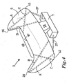
- Figure 4 illustrates a number of possible paths for tethering members:
- the central region is defined as the region covering the windscreen 9, while the upper corners 29, 33 are substantially located over or adjacent to the A pillars.
- tethering members may be used, such as one, two, three, four or five. For symmetry reasons, it is generally preferred to use the same number of tethering members for each half of the airbag, but the number may also differ.
- the tethering member may extend over less than half the lateral width w of the airbag, preferably less than 40% and most preferably less than 30%.
- tethering members are preferably attached at the projected periphery of the airbag, most preferably in the peripheral seam, but can be attached at any location of the airbag. Therefore, there are in principle an endless number of different paths of the tethering member available.
- the tethering member according to the invention may further be used in order to control the shape of the airbag 5 during a deployment process. Examples are illustrated by Figures 5a, 5b and 6a, 6b .
- a third embodiment of the invention is disclosed, wherein the tethering members 51, 53 extend inside of the airbag 5. They are, in addition to being attached at the ends, also attached at an additional location at the interior of the airbag 5 by a tear seam 55, 57, in this case adjacent to a lateral edge 59, 61 at the projected periphery of the airbag 5.
- the tear seams are designed to tear at a desired selectable applied force.
- a first portion 63 of the airbag is inflated, as illustrated in Figure 5a .
- the first portion 63 is restricted since the upper corners 29, 35 are restrained by the tethering members 51, 53, which during this phase still are attached to the interior of the airbag 5.
- the tear seams 55, 57 are torn and the airbag 5 expands further to its full deployed volume as in Figure 5b .
- the upper corners 29, 35 are then raised to respective positions, wherein they are located at least partly over or close to the A-pillars of the vehicle.
- Figures 5a and 5b disclose tethering members 51, 53 extending inside of the airbag 5, it would also be possible to use a tear seam for a tethering member extending along the outer surface of the airbag 5. The tear seam would then be located on the exterior of the airbag 5.
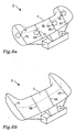
- FIGS 6a and 6b illustrate a fourth embodiment of the invention.
- Tethering members 65, 67, 71, 79 comprise a tear seam 73, 75, 77, 79 attaching each tethering member to itself at a location somewhere in between the ends.
- a first portion 81 of the airbag is inflated, as illustrated in Figure 6a .
- the first portion 81 is restricted by the tethering members 65, 67, 71, 79, which during this phase still are attached to themselves.
- the tear seams 65, 67, 71, 79 are torn and the airbag 5 expands further to its full deployed volume as in Figure 6b .
- the tethering members 65, 67, 71, 79 may extend inside of the airbag 5, as illustrated, or along the outer surface of the airbag 5. Even if Figures 6a and 6b illustrate four tethering members, any number, such as one, two, three or more may be used.
- the force at which the tear seam breaks may be selected individually for each tear seam, in order to control the deployment process of the airbag in greater detail.
Landscapes
- Engineering & Computer Science (AREA)
- Mechanical Engineering (AREA)
- Air Bags (AREA)
Claims (11)
- Airbag (5) de protection de piéton pour un véhicule (1),
ledit airbag (5) étant conçu pour être déployé le long d'un pare-brise (9) et/ou de montants avant (11) dudit véhicule (1) et étant gonflable pour passer à un état déployé, ledit airbag (5) comportant une périphérie projetée, l'expression périphérie projetée désignant le concept selon lequel ledit airbag (5), dans son état déployé, est projeté sur un plan formant un plan principal d'un pare-brise dudit véhicule (1),
caractérisé en ce que
ledit airbag (5) comprend au moins un élément d'arrimage (27, 33 ; 51, 53 ; 65, 67, 69, 71) raccordant une région supérieure (25) dudit airbag (5) à une région inférieure (23) dudit airbag (5) le long d'un trajet, ledit trajet étant situé à l'intérieur de ladite périphérie projetée dudit airbag (5), lorsque ledit airbag (5) se trouve dans ledit état déployé, ladite région supérieure (25) de l'airbag (5) étant définie comme la région de l'airbag (5) déployé située au-dessus d'une ligne imaginaire (L) dans le sens latéral, passant par l'airbag (5) déployé à la moitié de sa hauteur (h) le long dudit pare-brise (9) au niveau d'une ligne médiane, ladite région inférieure (23) étant définie comme étant située en dessous de ladite ligne imaginaire (L), ladite ligne médiane divisant ledit airbag (5) en une moitié droite et une moitié gauche,
ledit ou lesdits éléments d'arrimage (27, 33 ; 51, 53 ; 65, 67, 69, 71) étant une courroie ou une sangle, ledit ou lesdits éléments d'arrimage (27, 33 ; 51, 53 ; 65, 67, 69, 71) étant situés à l'intérieur dudit airbag (5). - Airbag (5) de protection de piéton selon la revendication 1, ledit élément d'arrimage (27, 33 ; 51, 53 ; 65, 67, 69, 71) comportant une première extrémité (27a ; 33a ; 39a ; 41a) et une seconde extrémité (27b ; 33b ; 39b ; 41b), lesdites première et seconde extrémités étant toutes deux attachées audit airbag (5).
- Airbag (5) de protection de piéton selon la revendication 2, dans lequel au moins une extrémité (27a, 27b ; 33a, 33b) desdites première et seconde extrémités dudit élément d'arrimage est attachée au niveau de ladite périphérie projetée dudit airbag (5) ou en position adjacente à celle-ci, de préférence dans un joint périphérique.
- Airbag (5) de protection de piéton selon l'une quelconque des revendications précédentes, dans lequel ledit ou lesdits éléments d'arrimage (51, 53 ; 65, 67, 69, 71) comprennent un joint déchirable (55, 57 ; 73, 75, 77, 79) attachant ledit ou lesdits éléments d'arrimage à lui-même ou audit airbag (5).
- Airbag (5) de protection de piéton selon la revendication 4, dans lequel ledit ou lesdits éléments d'arrimage (51, 53) sont attachés à une partie intérieure dudit airbag (5) au niveau d'au moins un emplacement supplémentaire différent de ladite périphérie projetée dudit airbag (5).
- Airbag (5) de protection de piéton selon la revendication 5, dans lequel ledit ou lesdits éléments d'arrimage (51, 53) sont attachés à la partie intérieure dudit airbag (5) au niveau dudit ou desdits emplacements supplémentaires au moyen d'un joint déchirable (55, 57).
- Airbag (5) de protection de piéton selon l'une quelconque des revendications précédentes, dans lequel ledit ou lesdits éléments d'arrimage (27, 33 ; 51, 53 ; 67, 71) s'étendent d'un coin supérieur (29, 35) dudit airbag (5) à un coin inférieur (31) dudit airbag (5).
- Airbag (5) de protection de piéton selon l'une quelconque des revendications 1 à 6, dans lequel ledit ou lesdits éléments d'arrimage s'étendent d'un coin supérieur (47) d'une région centrale (49) à un coin inférieur (43, 45) dudit airbag (5) .
- Véhicule comprenant un airbag (5) de protection de piéton selon l'une quelconque des revendications 1 à 8.
- Procédé de déploiement d'un airbag (5) de protection de piéton le long du pare-brise (9) et/ou de montants avant (11) d'un véhicule (1), ledit airbag (5) étant gonflable pour passer à un état déployé, comportant une périphérie projetée et comprenant au moins un élément d'arrimage (27, 33 ; 51, 53 ; 65, 67, 69, 71) qui est une courroie ou une sangle, l'expression périphérie projetée désignant le concept selon lequel ledit airbag (5), dans son état déployé, est projeté sur un plan formant un plan principal d'un pare-brise dudit véhicule (1), ledit ou lesdits éléments d'arrimage (27, 33 ; 51, 53 ; 65, 67, 69, 71) étant situés à l'intérieur dudit airbag (5), ledit ou lesdits éléments d'arrimage (27, 33 ; 51, 53 ; 65, 67, 69, 71) raccordant une région supérieure (25) dudit airbag (5) à une région inférieure (23) dudit airbag (5) le long d'un trajet, ledit trajet étant situé à l'intérieur de ladite périphérie projetée dudit airbag (5), lorsque celui-ci se trouve dans ledit état déployé, ladite région supérieure (25) de l'airbag (5) étant définie comme la région de l'airbag (5) déployé située au-dessus d'une ligne imaginaire (L) dans le sens latéral, passant par l'airbag (5) déployé à la moitié de sa hauteur (h) le long dudit pare-brise (9) au niveau d'une ligne médiane, ladite région inférieure (23) étant définie comme étant située en dessous de ladite ligne imaginaire (L), ladite ligne médiane divisant ledit airbag (5) en une moitié droite et une moitié gauche,
la forme dudit airbag (5) étant contrôlée au cours du processus de déploiement au moyen dudit ou desdits éléments d'arrimage (27, 33 ; 51, 53 ; 65, 67, 69, 71). - Procédé selon la revendication 10, dans lequel ledit ou lesdits éléments d'arrimage (51, 53 ; 65, 67, 69, 71) comprennent au moins un joint déchirable (55, 57 ; 73, 75, 77, 79) attachant ledit ou lesdits éléments d'arrimage audit airbag (5) et/ou à lui-même, ledit procédé comprenant les étapes suivantes pour contrôler ladite forme dudit airbag au cours du processus de déploiement :a) gonfler une première partie (63, 81) dudit airbag (5), ladite première partie étant restreinte par ledit ou lesdits éléments d'arrimage (51, 53 ; 65, 67, 69, 71),b) déchirer ledit ou lesdits joints déchirables (55, 57),c) gonfler une partie suivante dudit airbag (5).
Priority Applications (3)
| Application Number | Priority Date | Filing Date | Title |
|---|---|---|---|
| EP11191104.6A EP2599669B1 (fr) | 2011-11-29 | 2011-11-29 | Airbag de protection des piétons |
| US13/686,500 US8955634B2 (en) | 2011-11-29 | 2012-11-27 | Pedestrian protection airbag |
| CN201210495232.XA CN103129509B (zh) | 2011-11-29 | 2012-11-28 | 行人保护气囊 |
Applications Claiming Priority (1)
| Application Number | Priority Date | Filing Date | Title |
|---|---|---|---|
| EP11191104.6A EP2599669B1 (fr) | 2011-11-29 | 2011-11-29 | Airbag de protection des piétons |
Publications (2)
| Publication Number | Publication Date |
|---|---|
| EP2599669A1 EP2599669A1 (fr) | 2013-06-05 |
| EP2599669B1 true EP2599669B1 (fr) | 2015-07-22 |
Family
ID=45044414
Family Applications (1)
| Application Number | Title | Priority Date | Filing Date |
|---|---|---|---|
| EP11191104.6A Active EP2599669B1 (fr) | 2011-11-29 | 2011-11-29 | Airbag de protection des piétons |
Country Status (3)
| Country | Link |
|---|---|
| US (1) | US8955634B2 (fr) |
| EP (1) | EP2599669B1 (fr) |
| CN (1) | CN103129509B (fr) |
Cited By (1)
| Publication number | Priority date | Publication date | Assignee | Title |
|---|---|---|---|---|
| US11608025B2 (en) | 2017-05-05 | 2023-03-21 | Paul Philippe Cord | Protection system for persons and goods comprising an inflatable structure with long duration of action |
Families Citing this family (26)
| Publication number | Priority date | Publication date | Assignee | Title |
|---|---|---|---|---|
| EP2481647B1 (fr) * | 2011-01-26 | 2013-10-02 | Autoliv Development AB | Agencement d'airbag pour piétons |
| JP5761260B2 (ja) * | 2013-06-25 | 2015-08-12 | トヨタ自動車株式会社 | 車両衝突被害軽減システム |
| CN104417483B (zh) * | 2013-08-30 | 2018-08-14 | 比亚迪股份有限公司 | 一种车用行人保护安全气囊及装置 |
| GB2520686B (en) * | 2013-11-27 | 2020-04-15 | Autoliv Dev | Pedestrian airbag with internal tether |
| US9399441B2 (en) * | 2014-03-25 | 2016-07-26 | Ford Global Technologies, Llc | Shape adaptive passenger airbag |
| KR20150124003A (ko) * | 2014-04-25 | 2015-11-05 | 현대자동차주식회사 | 차량의 보행자 에어백 시스템 |
| KR101664017B1 (ko) * | 2014-07-25 | 2016-10-10 | 현대모비스 주식회사 | 보행자 보호용 에어백장치 |
| KR101640247B1 (ko) * | 2014-08-29 | 2016-07-15 | 현대모비스 주식회사 | 보행자 보호용 에어백장치 |
| JP6327108B2 (ja) * | 2014-10-21 | 2018-05-23 | トヨタ自動車株式会社 | エアバッグ装置 |
| JP6519275B2 (ja) * | 2015-03-31 | 2019-05-29 | Joyson Safety Systems Japan株式会社 | エアバッグ及び歩行者用エアバッグ装置 |
| JP6097782B2 (ja) * | 2015-03-31 | 2017-03-15 | 富士重工業株式会社 | 車外用エアバッグ |
| DE102015214354B4 (de) * | 2015-07-29 | 2020-01-02 | Joyson Safety Systems Germany Gmbh | Gassackanordnung für ein Kraftfahrzeug |
| KR102508056B1 (ko) * | 2015-08-13 | 2023-03-09 | 현대모비스 주식회사 | 에어백 장치 |
| JP6451597B2 (ja) * | 2015-11-06 | 2019-01-16 | トヨタ自動車株式会社 | 運転席用エアバッグ装置 |
| US10011243B2 (en) * | 2016-01-29 | 2018-07-03 | Ford Global Technologies, Llc | Passenger airbag having head orienting extension and depression |
| US9956937B2 (en) * | 2016-09-07 | 2018-05-01 | Ford Global Technologies, Llc | Airbag with at least one extension |
| JP6540649B2 (ja) * | 2016-10-11 | 2019-07-10 | トヨタ自動車株式会社 | 歩行者保護用エアバッグ装置 |
| US10391968B2 (en) * | 2016-10-21 | 2019-08-27 | Ford Global Technologies, Llc | Airbag assembly including internal and external tethers |
| EP3590774B1 (fr) * | 2018-07-05 | 2021-05-26 | Autoliv Development AB | Dispositif airbag de protection des piétons |
| JP7332349B2 (ja) * | 2018-07-05 | 2023-08-23 | オートリブ ディベロップメント エービー | 歩行者保護エアバッグ装置 |
| CN108995622A (zh) * | 2018-08-09 | 2018-12-14 | 吉利汽车研究院(宁波)有限公司 | 防摔落行人保护气囊及汽车 |
| EP3718608B1 (fr) | 2019-04-01 | 2021-11-17 | Volvo Car Corporation | Structure gonflable |
| US11518335B2 (en) * | 2019-07-02 | 2022-12-06 | Joyson Safety Systems Acquisition Llc | Driver side airbag module |
| US11274791B2 (en) * | 2019-09-12 | 2022-03-15 | Michael Francis Pelc | Vehicular fluid capture system |
| KR20210034249A (ko) * | 2019-09-20 | 2021-03-30 | 현대모비스 주식회사 | 에어백 장치 |
| JP2022053575A (ja) * | 2020-09-25 | 2022-04-06 | 株式会社Subaru | 車両の車外保護装置 |
Family Cites Families (18)
| Publication number | Priority date | Publication date | Assignee | Title |
|---|---|---|---|---|
| MX9304559A (es) * | 1992-09-01 | 1994-03-31 | Morton Int Inc | Cuerdas con costuras rascables para cojin de bolsa inflable. |
| US5813696A (en) * | 1996-10-28 | 1998-09-29 | Trw Vehicle Safety Systems Inc. | Air bag with tether |
| US7134691B2 (en) * | 2001-05-23 | 2006-11-14 | Delphi Technologies, Inc. | Air bag cushion including break-away tethers |
| JP3975866B2 (ja) * | 2002-08-30 | 2007-09-12 | 豊田合成株式会社 | 歩行者保護用エアバッグ装置 |
| DE10341368A1 (de) | 2003-09-03 | 2005-04-07 | Takata-Petri Ag | Sicherheitseinrichtung an einem Kraftfahrzeug zum Schutz von Fußgängern und Radfahrern |
| US7195281B2 (en) * | 2003-12-11 | 2007-03-27 | Autoliv Asp, Inc. | Expansion-controlled joints in airbags for out-of-position occupants and cushion positioning |
| US7377548B2 (en) * | 2005-05-06 | 2008-05-27 | Tk Holdings Inc. | Adaptive depth airbag |
| DE102006033670B4 (de) * | 2005-07-26 | 2011-08-25 | Honda Motor Co., Ltd. | Fahrzeug mit Kollisionsobjekt-Schutzeinrichtung |
| JP4621119B2 (ja) * | 2005-11-18 | 2011-01-26 | 本田技研工業株式会社 | 衝突物保護装置 |
| CN101374699A (zh) * | 2006-01-17 | 2009-02-25 | 高田株式会社 | 行人用气囊装置 |
| CN101389510B (zh) * | 2006-02-27 | 2011-07-27 | 马自达汽车株式会社 | 安全气囊装置 |
| US8262130B2 (en) * | 2007-07-30 | 2012-09-11 | Trw Vehicle Safety Systems Inc. | Air bag with improved tear stitch |
| JP2009101793A (ja) * | 2007-10-22 | 2009-05-14 | Toyoda Gosei Co Ltd | 歩行者用エアバッグ装置 |
| CN101327774A (zh) * | 2008-08-01 | 2008-12-24 | 王运韬 | 汽车主动保护防撞安全气囊 |
| US8016066B1 (en) * | 2010-06-10 | 2011-09-13 | Trw Vehicle Safety Systems Inc. | Pedestrian air bag |
| EP2502794B1 (fr) * | 2011-03-25 | 2013-12-11 | Autoliv Development AB | Agencement d'airbag pour piétons |
| EP2520471B1 (fr) * | 2011-05-05 | 2014-02-12 | Autoliv Development AB | Agencement d'airbag pour piétons |
| EP2548772B1 (fr) * | 2011-07-20 | 2014-03-05 | Autoliv Development AB | Agencement d'airbag |
-
2011
- 2011-11-29 EP EP11191104.6A patent/EP2599669B1/fr active Active
-
2012
- 2012-11-27 US US13/686,500 patent/US8955634B2/en active Active
- 2012-11-28 CN CN201210495232.XA patent/CN103129509B/zh active Active
Cited By (1)
| Publication number | Priority date | Publication date | Assignee | Title |
|---|---|---|---|---|
| US11608025B2 (en) | 2017-05-05 | 2023-03-21 | Paul Philippe Cord | Protection system for persons and goods comprising an inflatable structure with long duration of action |
Also Published As
| Publication number | Publication date |
|---|---|
| EP2599669A1 (fr) | 2013-06-05 |
| CN103129509A (zh) | 2013-06-05 |
| US20130200603A1 (en) | 2013-08-08 |
| CN103129509B (zh) | 2016-08-17 |
| US8955634B2 (en) | 2015-02-17 |
Similar Documents
| Publication | Publication Date | Title |
|---|---|---|
| EP2599669B1 (fr) | Airbag de protection des piétons | |
| JP6734880B2 (ja) | カーテンエアバッグ用一体成形織り布地の費用効果的使用 | |
| US9539978B2 (en) | Curtain airbag for a vehicle | |
| US7073619B2 (en) | Vehicle frontal airbag system | |
| JP4175338B2 (ja) | エアバッグ装置 | |
| EP2617607B1 (fr) | Agencement d'airbag | |
| JP2005138749A (ja) | 歩行者等の保護装置 | |
| JP2014503423A (ja) | 自動車両用のガスバッグ構成 | |
| EP2776290B1 (fr) | Dispositif de protection contre les impacts avec un couvercle | |
| US7213837B2 (en) | Airbag module | |
| EP3012161B1 (fr) | Dispositif airbag de protection des piétons | |
| KR101482731B1 (ko) | 차량을 위한 보행자 보호 에어백 | |
| US20180099639A1 (en) | External airbag | |
| EP2360068B1 (fr) | Système d'airbag de véhicule | |
| JP2008143301A (ja) | 歩行者保護用フードエアバッグ装置 | |
| US9139154B2 (en) | Side curtain airbag for vehicle having inflatable extension | |
| EP2617608A1 (fr) | Agencement d'airbag piéton sur un véhicule à moteur | |
| JP2008254492A (ja) | 歩行者保護装置 | |
| US7273226B2 (en) | Air bag device and motorbike with air bag device | |
| CN112550203A (zh) | 车辆的安全气囊装置 | |
| JP6137075B2 (ja) | 歩行者保護エアバッグ装置 | |
| EP2452856B1 (fr) | Airbag gonflable | |
| EP2617609B1 (fr) | Agencement d'airbag piéton sur un véhicule à moteur | |
| US20150054262A1 (en) | Airbag device for vehicle | |
| JP4570078B2 (ja) | エアバッグ及び非乗員保護装置 |
Legal Events
| Date | Code | Title | Description |
|---|---|---|---|
| PUAI | Public reference made under article 153(3) epc to a published international application that has entered the european phase |
Free format text: ORIGINAL CODE: 0009012 |
|
| AK | Designated contracting states |
Kind code of ref document: A1 Designated state(s): AL AT BE BG CH CY CZ DE DK EE ES FI FR GB GR HR HU IE IS IT LI LT LU LV MC MK MT NL NO PL PT RO RS SE SI SK SM TR |
|
| AX | Request for extension of the european patent |
Extension state: BA ME |
|
| 17P | Request for examination filed |
Effective date: 20131205 |
|
| RBV | Designated contracting states (corrected) |
Designated state(s): AL AT BE BG CH CY CZ DE DK EE ES FI FR GB GR HR HU IE IS IT LI LT LU LV MC MK MT NL NO PL PT RO RS SE SI SK SM TR |
|
| RIC1 | Information provided on ipc code assigned before grant |
Ipc: B60R 21/36 20110101AFI20140102BHEP |
|
| 17Q | First examination report despatched |
Effective date: 20140225 |
|
| REG | Reference to a national code |
Ref country code: DE Ref legal event code: R079 Ref document number: 602011017997 Country of ref document: DE Free format text: PREVIOUS MAIN CLASS: B60R0021360000 Ipc: B60R0021233800 |
|
| GRAP | Despatch of communication of intention to grant a patent |
Free format text: ORIGINAL CODE: EPIDOSNIGR1 |
|
| RIC1 | Information provided on ipc code assigned before grant |
Ipc: B60R 21/2338 20110101AFI20150416BHEP Ipc: B60R 21/2342 20110101ALI20150416BHEP Ipc: B60R 21/36 20110101ALI20150416BHEP |
|
| INTG | Intention to grant announced |
Effective date: 20150430 |
|
| GRAS | Grant fee paid |
Free format text: ORIGINAL CODE: EPIDOSNIGR3 |
|
| GRAA | (expected) grant |
Free format text: ORIGINAL CODE: 0009210 |
|
| AK | Designated contracting states |
Kind code of ref document: B1 Designated state(s): AL AT BE BG CH CY CZ DE DK EE ES FI FR GB GR HR HU IE IS IT LI LT LU LV MC MK MT NL NO PL PT RO RS SE SI SK SM TR |
|
| REG | Reference to a national code |
Ref country code: GB Ref legal event code: FG4D |
|
| REG | Reference to a national code |
Ref country code: CH Ref legal event code: EP |
|
| REG | Reference to a national code |
Ref country code: IE Ref legal event code: FG4D |
|
| REG | Reference to a national code |
Ref country code: AT Ref legal event code: REF Ref document number: 737691 Country of ref document: AT Kind code of ref document: T Effective date: 20150815 |
|
| REG | Reference to a national code |
Ref country code: DE Ref legal event code: R096 Ref document number: 602011017997 Country of ref document: DE |
|
| REG | Reference to a national code |
Ref country code: SE Ref legal event code: TRGR |
|
| REG | Reference to a national code |
Ref country code: AT Ref legal event code: MK05 Ref document number: 737691 Country of ref document: AT Kind code of ref document: T Effective date: 20150722 |
|
| REG | Reference to a national code |
Ref country code: LT Ref legal event code: MG4D |
|
| REG | Reference to a national code |
Ref country code: NL Ref legal event code: MP Effective date: 20150722 |
|
| PG25 | Lapsed in a contracting state [announced via postgrant information from national office to epo] |
Ref country code: NO Free format text: LAPSE BECAUSE OF FAILURE TO SUBMIT A TRANSLATION OF THE DESCRIPTION OR TO PAY THE FEE WITHIN THE PRESCRIBED TIME-LIMIT Effective date: 20151022 Ref country code: FI Free format text: LAPSE BECAUSE OF FAILURE TO SUBMIT A TRANSLATION OF THE DESCRIPTION OR TO PAY THE FEE WITHIN THE PRESCRIBED TIME-LIMIT Effective date: 20150722 Ref country code: LV Free format text: LAPSE BECAUSE OF FAILURE TO SUBMIT A TRANSLATION OF THE DESCRIPTION OR TO PAY THE FEE WITHIN THE PRESCRIBED TIME-LIMIT Effective date: 20150722 Ref country code: GR Free format text: LAPSE BECAUSE OF FAILURE TO SUBMIT A TRANSLATION OF THE DESCRIPTION OR TO PAY THE FEE WITHIN THE PRESCRIBED TIME-LIMIT Effective date: 20151023 Ref country code: LT Free format text: LAPSE BECAUSE OF FAILURE TO SUBMIT A TRANSLATION OF THE DESCRIPTION OR TO PAY THE FEE WITHIN THE PRESCRIBED TIME-LIMIT Effective date: 20150722 |
|
| PG25 | Lapsed in a contracting state [announced via postgrant information from national office to epo] |
Ref country code: IS Free format text: LAPSE BECAUSE OF FAILURE TO SUBMIT A TRANSLATION OF THE DESCRIPTION OR TO PAY THE FEE WITHIN THE PRESCRIBED TIME-LIMIT Effective date: 20151122 Ref country code: PT Free format text: LAPSE BECAUSE OF FAILURE TO SUBMIT A TRANSLATION OF THE DESCRIPTION OR TO PAY THE FEE WITHIN THE PRESCRIBED TIME-LIMIT Effective date: 20151123 Ref country code: ES Free format text: LAPSE BECAUSE OF FAILURE TO SUBMIT A TRANSLATION OF THE DESCRIPTION OR TO PAY THE FEE WITHIN THE PRESCRIBED TIME-LIMIT Effective date: 20150722 Ref country code: PL Free format text: LAPSE BECAUSE OF FAILURE TO SUBMIT A TRANSLATION OF THE DESCRIPTION OR TO PAY THE FEE WITHIN THE PRESCRIBED TIME-LIMIT Effective date: 20150722 Ref country code: AT Free format text: LAPSE BECAUSE OF FAILURE TO SUBMIT A TRANSLATION OF THE DESCRIPTION OR TO PAY THE FEE WITHIN THE PRESCRIBED TIME-LIMIT Effective date: 20150722 Ref country code: HR Free format text: LAPSE BECAUSE OF FAILURE TO SUBMIT A TRANSLATION OF THE DESCRIPTION OR TO PAY THE FEE WITHIN THE PRESCRIBED TIME-LIMIT Effective date: 20150722 Ref country code: RS Free format text: LAPSE BECAUSE OF FAILURE TO SUBMIT A TRANSLATION OF THE DESCRIPTION OR TO PAY THE FEE WITHIN THE PRESCRIBED TIME-LIMIT Effective date: 20150722 |
|
| REG | Reference to a national code |
Ref country code: DE Ref legal event code: R097 Ref document number: 602011017997 Country of ref document: DE |
|
| PG25 | Lapsed in a contracting state [announced via postgrant information from national office to epo] |
Ref country code: IT Free format text: LAPSE BECAUSE OF FAILURE TO SUBMIT A TRANSLATION OF THE DESCRIPTION OR TO PAY THE FEE WITHIN THE PRESCRIBED TIME-LIMIT Effective date: 20150722 Ref country code: EE Free format text: LAPSE BECAUSE OF FAILURE TO SUBMIT A TRANSLATION OF THE DESCRIPTION OR TO PAY THE FEE WITHIN THE PRESCRIBED TIME-LIMIT Effective date: 20150722 Ref country code: CZ Free format text: LAPSE BECAUSE OF FAILURE TO SUBMIT A TRANSLATION OF THE DESCRIPTION OR TO PAY THE FEE WITHIN THE PRESCRIBED TIME-LIMIT Effective date: 20150722 Ref country code: SK Free format text: LAPSE BECAUSE OF FAILURE TO SUBMIT A TRANSLATION OF THE DESCRIPTION OR TO PAY THE FEE WITHIN THE PRESCRIBED TIME-LIMIT Effective date: 20150722 Ref country code: DK Free format text: LAPSE BECAUSE OF FAILURE TO SUBMIT A TRANSLATION OF THE DESCRIPTION OR TO PAY THE FEE WITHIN THE PRESCRIBED TIME-LIMIT Effective date: 20150722 |
|
| PLBE | No opposition filed within time limit |
Free format text: ORIGINAL CODE: 0009261 |
|
| STAA | Information on the status of an ep patent application or granted ep patent |
Free format text: STATUS: NO OPPOSITION FILED WITHIN TIME LIMIT |
|
| PG25 | Lapsed in a contracting state [announced via postgrant information from national office to epo] |
Ref country code: RO Free format text: LAPSE BECAUSE OF FAILURE TO SUBMIT A TRANSLATION OF THE DESCRIPTION OR TO PAY THE FEE WITHIN THE PRESCRIBED TIME-LIMIT Effective date: 20150722 |
|
| 26N | No opposition filed |
Effective date: 20160425 |
|
| PG25 | Lapsed in a contracting state [announced via postgrant information from national office to epo] |
Ref country code: MC Free format text: LAPSE BECAUSE OF FAILURE TO SUBMIT A TRANSLATION OF THE DESCRIPTION OR TO PAY THE FEE WITHIN THE PRESCRIBED TIME-LIMIT Effective date: 20150722 Ref country code: LU Free format text: LAPSE BECAUSE OF FAILURE TO SUBMIT A TRANSLATION OF THE DESCRIPTION OR TO PAY THE FEE WITHIN THE PRESCRIBED TIME-LIMIT Effective date: 20151129 |
|
| REG | Reference to a national code |
Ref country code: CH Ref legal event code: PL |
|
| PG25 | Lapsed in a contracting state [announced via postgrant information from national office to epo] |
Ref country code: LI Free format text: LAPSE BECAUSE OF NON-PAYMENT OF DUE FEES Effective date: 20151130 Ref country code: CH Free format text: LAPSE BECAUSE OF NON-PAYMENT OF DUE FEES Effective date: 20151130 |
|
| REG | Reference to a national code |
Ref country code: IE Ref legal event code: MM4A |
|
| REG | Reference to a national code |
Ref country code: FR Ref legal event code: ST Effective date: 20160729 |
|
| PG25 | Lapsed in a contracting state [announced via postgrant information from national office to epo] |
Ref country code: SI Free format text: LAPSE BECAUSE OF FAILURE TO SUBMIT A TRANSLATION OF THE DESCRIPTION OR TO PAY THE FEE WITHIN THE PRESCRIBED TIME-LIMIT Effective date: 20150722 |
|
| PG25 | Lapsed in a contracting state [announced via postgrant information from national office to epo] |
Ref country code: IE Free format text: LAPSE BECAUSE OF NON-PAYMENT OF DUE FEES Effective date: 20151129 |
|
| PG25 | Lapsed in a contracting state [announced via postgrant information from national office to epo] |
Ref country code: FR Free format text: LAPSE BECAUSE OF NON-PAYMENT OF DUE FEES Effective date: 20151130 |
|
| PG25 | Lapsed in a contracting state [announced via postgrant information from national office to epo] |
Ref country code: BE Free format text: LAPSE BECAUSE OF FAILURE TO SUBMIT A TRANSLATION OF THE DESCRIPTION OR TO PAY THE FEE WITHIN THE PRESCRIBED TIME-LIMIT Effective date: 20150722 |
|
| PG25 | Lapsed in a contracting state [announced via postgrant information from national office to epo] |
Ref country code: HU Free format text: LAPSE BECAUSE OF FAILURE TO SUBMIT A TRANSLATION OF THE DESCRIPTION OR TO PAY THE FEE WITHIN THE PRESCRIBED TIME-LIMIT; INVALID AB INITIO Effective date: 20111129 Ref country code: SM Free format text: LAPSE BECAUSE OF FAILURE TO SUBMIT A TRANSLATION OF THE DESCRIPTION OR TO PAY THE FEE WITHIN THE PRESCRIBED TIME-LIMIT Effective date: 20150722 Ref country code: BG Free format text: LAPSE BECAUSE OF FAILURE TO SUBMIT A TRANSLATION OF THE DESCRIPTION OR TO PAY THE FEE WITHIN THE PRESCRIBED TIME-LIMIT Effective date: 20150722 |
|
| PG25 | Lapsed in a contracting state [announced via postgrant information from national office to epo] |
Ref country code: CY Free format text: LAPSE BECAUSE OF FAILURE TO SUBMIT A TRANSLATION OF THE DESCRIPTION OR TO PAY THE FEE WITHIN THE PRESCRIBED TIME-LIMIT Effective date: 20150722 Ref country code: NL Free format text: LAPSE BECAUSE OF FAILURE TO SUBMIT A TRANSLATION OF THE DESCRIPTION OR TO PAY THE FEE WITHIN THE PRESCRIBED TIME-LIMIT Effective date: 20150722 |
|
| PG25 | Lapsed in a contracting state [announced via postgrant information from national office to epo] |
Ref country code: MT Free format text: LAPSE BECAUSE OF FAILURE TO SUBMIT A TRANSLATION OF THE DESCRIPTION OR TO PAY THE FEE WITHIN THE PRESCRIBED TIME-LIMIT Effective date: 20150722 |
|
| PG25 | Lapsed in a contracting state [announced via postgrant information from national office to epo] |
Ref country code: TR Free format text: LAPSE BECAUSE OF FAILURE TO SUBMIT A TRANSLATION OF THE DESCRIPTION OR TO PAY THE FEE WITHIN THE PRESCRIBED TIME-LIMIT Effective date: 20150722 Ref country code: MK Free format text: LAPSE BECAUSE OF FAILURE TO SUBMIT A TRANSLATION OF THE DESCRIPTION OR TO PAY THE FEE WITHIN THE PRESCRIBED TIME-LIMIT Effective date: 20150722 |
|
| PG25 | Lapsed in a contracting state [announced via postgrant information from national office to epo] |
Ref country code: AL Free format text: LAPSE BECAUSE OF FAILURE TO SUBMIT A TRANSLATION OF THE DESCRIPTION OR TO PAY THE FEE WITHIN THE PRESCRIBED TIME-LIMIT Effective date: 20150722 |
|
| PGFP | Annual fee paid to national office [announced via postgrant information from national office to epo] |
Ref country code: CZ Payment date: 20181218 Year of fee payment: 13 |
|
| PGFP | Annual fee paid to national office [announced via postgrant information from national office to epo] |
Ref country code: GB Payment date: 20181114 Year of fee payment: 8 |
|
| REG | Reference to a national code |
Ref country code: SE Ref legal event code: EUG |
|
| PG25 | Lapsed in a contracting state [announced via postgrant information from national office to epo] |
Ref country code: SE Free format text: LAPSE BECAUSE OF NON-PAYMENT OF DUE FEES Effective date: 20191130 |
|
| GBPC | Gb: european patent ceased through non-payment of renewal fee |
Effective date: 20191129 |
|
| PG25 | Lapsed in a contracting state [announced via postgrant information from national office to epo] |
Ref country code: GB Free format text: LAPSE BECAUSE OF NON-PAYMENT OF DUE FEES Effective date: 20191129 |
|
| PGFP | Annual fee paid to national office [announced via postgrant information from national office to epo] |
Ref country code: DE Payment date: 20231019 Year of fee payment: 13 |