EP2599613B1 - Three-dimensional shaping apparatus, three-dimensional shaping method, set-data creating apparatus for three-dimensional shaping apparatus, program for creating set-data for three-dimensional shaping apparatus, and computer-readable recording medium - Google Patents
Three-dimensional shaping apparatus, three-dimensional shaping method, set-data creating apparatus for three-dimensional shaping apparatus, program for creating set-data for three-dimensional shaping apparatus, and computer-readable recording medium Download PDFInfo
- Publication number
- EP2599613B1 EP2599613B1 EP12185195.0A EP12185195A EP2599613B1 EP 2599613 B1 EP2599613 B1 EP 2599613B1 EP 12185195 A EP12185195 A EP 12185195A EP 2599613 B1 EP2599613 B1 EP 2599613B1
- Authority
- EP
- European Patent Office
- Prior art keywords
- shaping
- ejection
- slice
- model
- supporting
- Prior art date
- Legal status (The legal status is an assumption and is not a legal conclusion. Google has not performed a legal analysis and makes no representation as to the accuracy of the status listed.)
- Active
Links
- 238000007493 shaping process Methods 0.000 title claims description 697
- 238000000034 method Methods 0.000 title claims description 53
- 239000000463 material Substances 0.000 claims description 1430
- 238000011084 recovery Methods 0.000 claims description 65
- 238000007790 scraping Methods 0.000 claims description 35
- 238000003475 lamination Methods 0.000 claims description 34
- 230000008859 change Effects 0.000 claims description 20
- 230000002829 reductive effect Effects 0.000 claims description 16
- 230000006870 function Effects 0.000 claims description 15
- 238000010030 laminating Methods 0.000 claims description 15
- 230000000670 limiting effect Effects 0.000 claims description 7
- 230000007423 decrease Effects 0.000 claims description 4
- 230000003247 decreasing effect Effects 0.000 claims description 4
- 238000003825 pressing Methods 0.000 claims description 4
- 229920005989 resin Polymers 0.000 description 220
- 239000011347 resin Substances 0.000 description 220
- 239000010410 layer Substances 0.000 description 204
- 238000001723 curing Methods 0.000 description 85
- 238000012545 processing Methods 0.000 description 18
- 230000000694 effects Effects 0.000 description 13
- 238000004364 calculation method Methods 0.000 description 11
- 239000007788 liquid Substances 0.000 description 8
- 238000002156 mixing Methods 0.000 description 8
- 230000008901 benefit Effects 0.000 description 7
- 230000015572 biosynthetic process Effects 0.000 description 7
- 239000012530 fluid Substances 0.000 description 7
- 238000009499 grossing Methods 0.000 description 7
- 230000008569 process Effects 0.000 description 7
- 230000004044 response Effects 0.000 description 7
- 230000007246 mechanism Effects 0.000 description 6
- 238000002844 melting Methods 0.000 description 6
- 230000008018 melting Effects 0.000 description 6
- 238000000926 separation method Methods 0.000 description 5
- 229920005992 thermoplastic resin Polymers 0.000 description 5
- 238000003848 UV Light-Curing Methods 0.000 description 4
- 238000010586 diagram Methods 0.000 description 4
- 238000006073 displacement reaction Methods 0.000 description 4
- 239000010808 liquid waste Substances 0.000 description 4
- 238000006243 chemical reaction Methods 0.000 description 3
- 238000001816 cooling Methods 0.000 description 3
- 238000011156 evaluation Methods 0.000 description 3
- 238000002474 experimental method Methods 0.000 description 3
- 238000010438 heat treatment Methods 0.000 description 3
- 238000004519 manufacturing process Methods 0.000 description 3
- 230000015654 memory Effects 0.000 description 3
- 230000036961 partial effect Effects 0.000 description 3
- 230000002265 prevention Effects 0.000 description 3
- 230000009467 reduction Effects 0.000 description 3
- 230000002411 adverse Effects 0.000 description 2
- 238000004140 cleaning Methods 0.000 description 2
- 238000013500 data storage Methods 0.000 description 2
- 238000002347 injection Methods 0.000 description 2
- 239000007924 injection Substances 0.000 description 2
- 238000001459 lithography Methods 0.000 description 2
- 239000000203 mixture Substances 0.000 description 2
- 230000003287 optical effect Effects 0.000 description 2
- 238000000016 photochemical curing Methods 0.000 description 2
- 239000000843 powder Substances 0.000 description 2
- 238000002360 preparation method Methods 0.000 description 2
- 239000002356 single layer Substances 0.000 description 2
- 238000003860 storage Methods 0.000 description 2
- HBGPNLPABVUVKZ-POTXQNELSA-N (1r,3as,4s,5ar,5br,7r,7ar,11ar,11br,13as,13br)-4,7-dihydroxy-3a,5a,5b,8,8,11a-hexamethyl-1-prop-1-en-2-yl-2,3,4,5,6,7,7a,10,11,11b,12,13,13a,13b-tetradecahydro-1h-cyclopenta[a]chrysen-9-one Chemical compound C([C@@]12C)CC(=O)C(C)(C)[C@@H]1[C@H](O)C[C@]([C@]1(C)C[C@@H]3O)(C)[C@@H]2CC[C@H]1[C@@H]1[C@]3(C)CC[C@H]1C(=C)C HBGPNLPABVUVKZ-POTXQNELSA-N 0.000 description 1
- PFRGGOIBYLYVKM-UHFFFAOYSA-N 15alpha-hydroxylup-20(29)-en-3-one Natural products CC(=C)C1CCC2(C)CC(O)C3(C)C(CCC4C5(C)CCC(=O)C(C)(C)C5CCC34C)C12 PFRGGOIBYLYVKM-UHFFFAOYSA-N 0.000 description 1
- 239000004925 Acrylic resin Substances 0.000 description 1
- 229920000178 Acrylic resin Polymers 0.000 description 1
- 101100063942 Neurospora crassa (strain ATCC 24698 / 74-OR23-1A / CBS 708.71 / DSM 1257 / FGSC 987) dot-1 gene Proteins 0.000 description 1
- 238000012356 Product development Methods 0.000 description 1
- SOKRNBGSNZXYIO-UHFFFAOYSA-N Resinone Natural products CC(=C)C1CCC2(C)C(O)CC3(C)C(CCC4C5(C)CCC(=O)C(C)(C)C5CCC34C)C12 SOKRNBGSNZXYIO-UHFFFAOYSA-N 0.000 description 1
- 229910000831 Steel Inorganic materials 0.000 description 1
- 230000009471 action Effects 0.000 description 1
- 238000013459 approach Methods 0.000 description 1
- 238000003491 array Methods 0.000 description 1
- 239000003795 chemical substances by application Substances 0.000 description 1
- 238000005352 clarification Methods 0.000 description 1
- 238000012937 correction Methods 0.000 description 1
- 239000003822 epoxy resin Substances 0.000 description 1
- 239000000284 extract Substances 0.000 description 1
- 238000001125 extrusion Methods 0.000 description 1
- 229910052736 halogen Inorganic materials 0.000 description 1
- 150000002367 halogens Chemical class 0.000 description 1
- LNEPOXFFQSENCJ-UHFFFAOYSA-N haloperidol Chemical compound C1CC(O)(C=2C=CC(Cl)=CC=2)CCN1CCCC(=O)C1=CC=C(F)C=C1 LNEPOXFFQSENCJ-UHFFFAOYSA-N 0.000 description 1
- 230000000977 initiatory effect Effects 0.000 description 1
- 238000007641 inkjet printing Methods 0.000 description 1
- 239000002648 laminated material Substances 0.000 description 1
- QSHDDOUJBYECFT-UHFFFAOYSA-N mercury Chemical compound [Hg] QSHDDOUJBYECFT-UHFFFAOYSA-N 0.000 description 1
- 229910052753 mercury Inorganic materials 0.000 description 1
- 230000004048 modification Effects 0.000 description 1
- 238000012986 modification Methods 0.000 description 1
- 239000003607 modifier Substances 0.000 description 1
- 229920000647 polyepoxide Polymers 0.000 description 1
- 238000007639 printing Methods 0.000 description 1
- 239000004065 semiconductor Substances 0.000 description 1
- 239000007787 solid Substances 0.000 description 1
- 239000002195 soluble material Substances 0.000 description 1
- 239000000243 solution Substances 0.000 description 1
- 239000010959 steel Substances 0.000 description 1
- 238000012360 testing method Methods 0.000 description 1
- 230000007704 transition Effects 0.000 description 1
- 150000003673 urethanes Chemical class 0.000 description 1
- 238000012795 verification Methods 0.000 description 1
- XLYOFNOQVPJJNP-UHFFFAOYSA-N water Substances O XLYOFNOQVPJJNP-UHFFFAOYSA-N 0.000 description 1
- 230000003313 weakening effect Effects 0.000 description 1
Images


Classifications
-
- B—PERFORMING OPERATIONS; TRANSPORTING
- B29—WORKING OF PLASTICS; WORKING OF SUBSTANCES IN A PLASTIC STATE IN GENERAL
- B29C—SHAPING OR JOINING OF PLASTICS; SHAPING OF MATERIAL IN A PLASTIC STATE, NOT OTHERWISE PROVIDED FOR; AFTER-TREATMENT OF THE SHAPED PRODUCTS, e.g. REPAIRING
- B29C64/00—Additive manufacturing, i.e. manufacturing of three-dimensional [3D] objects by additive deposition, additive agglomeration or additive layering, e.g. by 3D printing, stereolithography or selective laser sintering
- B29C64/40—Structures for supporting 3D objects during manufacture and intended to be sacrificed after completion thereof
Definitions
- the present invention relates to a three-dimensional shaping apparatus for fabricating a stereoscopic shaped object in an ink-jet manner, a three-dimensional shaping method, a set-data creating apparatus for a three-dimensional shaping apparatus, a set-data creating program for a three-dimensional shaping apparatus, and a computer-readable recording medium.
- laminate shaping methods which enable three-dimensional shaping.
- Such laminate shaping methods are adapted to slice a three-dimensional CAD data of a product, create overlapped thin plates as original product data, and laminate materials such as powder, resins, steel plates, paper and the like thereon to create a prototype.
- laminate shaping methods there are known an ink-jet method, a powder method, an optical shaping method, a sheet lamination method, an extrusion method, and the like.
- a liquefied material is injected, and then cured to form a layer through irradiation of ultraviolet light (UV), cooling or the like.
- UV ultraviolet light
- a three-dimensional shaping apparatus of a resin-lamination type is adapted to execute shaping by ejecting, onto a shaping plate, a model material configured to form the final shaped object and a supporting material, that is configured to support a base portion supporting the model and a protruding portion of the model material and that is finally removed, while scanning in the XY directions and laminating in a height direction.
- the model material and the supporting material are formed from resins having properties of being cured by irradiation with ultraviolet light.
- An ultraviolet-light lamp configured to emit ultraviolet light is scanned in the XY directions together with the nozzles for ejecting the model material and the supporting material so that the model material and the supporting material ejected from the nozzles are irradiated and cured with the ultraviolet light.
- Patent Document 1 Japanese Unexamined Patent Publication No. 2003-535712 .
- WO-A-2004/050323 discloses the features of the respective preambles of claims 1, 10, 13, 15 and 17.
- the roller portion 25 includes a roller main body 26 that is a rotating body, a blade 27 disposed to protrude relative to the surface of the roller main body 26, a bath 28 configured to collect the shaping material scraped off by the blade 27, and a suction pipe 29 for ejecting shaping material collected in the bath 28.
- the roller main body 26 is rotated in the direction opposed to the travel direction of head portion 20 (the clockwise direction in FIG. 33 ) and scrapes up flowing shaping material.
- the scraped-up shaping material adheres to the roller main body 26, transported to the blade 27, and then scraped off with the blade 27 and guided into the bath 28. As a result, the blade 27 is fixed in an attitude having a downward gradient towards the bath 28.
- the suction pipe 29 is connected with a liquid waste passage, and draws shaping material that has collected in the bath 28 using a pump or the like and stores the material in a liquid waste tank (not illustrated).
- a recovery mechanism using this type of roller portion 25 enables shaping while recovering the excess portion of resin as illustrated in FIG. 32 .
- the roller portion 25 should not usually come into contact with cured resin, it may make contact with cured resin due to the accuracy of the mechanical components such as the roller portion 25 or the vibration or the like of driving portions as illustrated in FIG. 33 . Even in the event that the roller portion 25 makes contact with cured resin, when the cured resin as illustrated in FIG. 34 is incorporated with the same type of cured resin and the cured layer is sufficiently thick, the cured layer is not subject to peeling.
- the bonding between different resins is strengthened at the boundary between different resins.
- This configuration strengthens the bonding at the boundary between different resins even when the roller portion 25 makes contact with resin, and therefore inhibits generation of peeling.
- the bonding strength between the supporting material SA and the model material MA is increased, the problem arises that it is difficult to remove the supporting material SA from the final shaped object after shaping.
- the present invention has been made in view of the above conventional problems and mainly aims at providing a three-dimensional shaping apparatus, a three-dimensional shaping method, a set-data creating apparatus for a three-dimensional shaping apparatus, a set-data creating program for a three-dimensional shaping apparatus, and a computer-readable recording medium which are capable of preventing scraping of resin due to contact of the roller portion with resin after curing without impeding the operational performance in relation to simple removal of supporting material from the final shaped object.
- a three-dimensional shaping apparatus is a three-dimensional shaping apparatus according to claim 1.
- the uppermost surface of the shaping material that is ejected at a position corresponding to the hollow portion can be separated in a downward configuration from the roller portion so as not to be scraped off by the roller portion, and thereby effectively avoid the problem of peeling of the layer or erroneous recovery, or the like.
- the hollow portion ES in the shaped object can be provided in the slice immediately above the boundary surface between the different types of shaping material when provided in the other shaping material of the model material MA or the supporting material SA.
- the hollow portion ES in the shaped object can be provided in the slice immediately below that in contact with the boundary surface between the different types of shaping material, or separated below by a predetermined number of slices from that position when provided in the first shaping material in the model material MA or the supporting material SA.
- the ejection control device 13 can control the shaping-material ejection device not to eject shaping material for a predetermined number of slices after the change. In this manner, by omitting a predetermined number of slices that are laminated immediately after in the boundary surface between different shaping materials such as the model material and the supporting material, a hollow portion omitting the number of slices is produced in the height direction so that the roller portion does not make contact with the surface of the shaping material and thus prevents recovery of the cured shaping material by the roller portion.
- a curing device 24 is further included for curing of the model material MA and the supporting material SA.
- the control device 10 executes control to cause reciprocating scanning in one direction of the head portion 20 with the horizontal driving device, and ejection of one of the model material MA and the supporting material SA onto the shaping plate 40 with the shaping-material ejection device in at least one of the forward path and the rearward path of the reciprocating scan, recovery of an excess portion of one of the model material MA and the supporting material SA in a flowing state with the roller portion 25 in at least one of the forward path and the rearward path of the reciprocating scan, and curing of the first of the model material MA and the supporting material SA with the curing device 24 in at least one of the forward path and the rearward path of the reciprocating scan, and further causes ejection of the second of the model material MA and the supporting material SA onto the shaping plate 40 with the shaping-material ejection device in at least one of the forward path and the rearward path of the reciprocating scan, recovery of an
- shaping is executed by forming a slice, displacing the relative position of the shaping plate 40 and the head portion 20 in the height direction using the vertical driving device and repeating the lamination of the slice.
- recovery of the excess portion and curing can be separately executed in relation to the model material and the supporting material, and thereby mixing of the model material and the supporting material at their boundary surface can be avoided and therefore enhances the quality of the shaped object.
- the thickness of the layer of ejected and cured shaping material that is positioned on the upper side of the boundary surface of bonding of different types of shaping material can be formed to be thicker than the thickness of other layers. In this manner, the possibility of erroneous recovery by the roller portion can be reduced by also increasing the thickness of the layer at the boundary surface between the different resin types.
- a predetermined number of slices can be set by the ejection control device 13 so that the excess portion is not recovered in the hollow portion ES in which either of the shaping materials is removed in a predetermined number of slices, and either of the shaping materials is laminated to at least two layers so that that one of the shaping materials does not come into contact with the roller portion.
- the ejection control device 13 can control the shaping-material ejection device to not eject at least one layer portion or two layer portions of the model material MA after switching of the shaping material ejected from the shaping-material ejection device from the supporting material SA to the model material MA. In this manner, a height difference can be set to avoid contact with the roller by omission of layers, and thereby avoid recovery of cured model material by the roller portion.
- the ejection control device 13 can control the shaping-material ejection device to not eject at least one layer portion or two layer portions of the supporting material SA after switching of the shaping material ejected from the shaping-material ejection device from the model material MA to the supporting material SA. In this manner, a height difference can be set to avoid contact with the roller by omission of layers, and thereby avoid recovery of cured supporting material by the roller portion.
- a method of three-dimensional shaping according to a tenthaspect is a three-dimensional shaping method according to claim 10.
- a predetermined number of slices of either of the shaping materials is omitted at the boundary surface between the different shaping materials being the model material and the supporting material to thereby create a hollow portion of the omitted slices in the height direction so that the roller portion does not make contact with the surface of the shaping material and thus prevent recovery of the cured shaping material by the roller portion.
- a height difference can be provided to avoid contact with the roller portion by forming layers of the same type in a thin configuration in proximity to the bonding portion between shaping materials of different types to thereby prevent erroneous recovery by the roller portion or peeling.
- the bonding strength between the model material and the supporting material can be weakened, and thereby obtains the advantage that the operation of removal of the supporting material after shaping can be facilitated.
- the method of three-dimensional shaping according to an eleventhaspect includes a further step of not ejecting shaping material from the shaping-material ejection device at the boundary surface between the different types of shaping material at which the model material MA and the supporting material SA changes from the first shaping material to the second shaping material in the height direction during laminating, or reducing the ejection amount, and completing shaping of the slice, and displacing the relative position of the ejection position by means of the vertical driving device to the ejection position of the next slice, ejecting the second of the shaping materials at a position corresponding to the boundary surface between different types of shaping material so that the upper surface of the ejected shaping material is separated from the roller portion 25, and a step of ejecting the second of the shaping materials at a position corresponding to the boundary surface between different types of shaping material during shaping of a slice after the next layer, and bringing the uppermost surface of the ejected material into contact with the roller portion 25, and thereby scraping off the excess portion of the second ejected shaping material
- a three-dimensional shaping method is a method in which the position of not ejecting either of the shaping materials or of limiting the ejection amount with the shaping-material ejection device is provided in the slice immediately above the boundary surface between the different types of shaping material at the ejection position of the second shaping material of the model material MA or the supporting material SA.
- a set-data creating apparatus for a three-dimensional shaping apparatus is a set-data creating apparatus according to claim 13.
- a predetermined number of slices of either of the shaping materials is omitted at the boundary surface between the different shaping materials being the model material and the supporting material to thereby create a hollow portion of the omitted slices in the height direction so that the roller portion does not make contact with the surface of the shaping material and thus prevent recovery of the cured shaping material by the roller portion.
- a set-data creating apparatus for a three-dimensional shaping apparatus is a set-data creating apparatus in which the position of creating the hollow portion ES is provided in the slice immediately below or separated below by a predetermined number of slices from the boundary surface at which the model material MA and the supporting material SA changes from the first shaping material to the second shaping material.
- a set-data creating program for a three-dimensional shaping apparatus is a set-data creating program for a three-dimensional shaping apparatus according to claim 15.
- a predetermined number of slices of either of the shaping materials is omitted at the boundary surface between the different shaping materials being the model material and the supporting material to thereby create a hollow portion of the omitted slices in the height direction so that the roller portion does not make contact with the surface of the shaping material and thus prevent recovery of the cured shaping material by the roller portion.
- a set-data creating program for a three-dimensional shaping apparatus is a set-data creating program for a three-dimensional shaping apparatus wherein when the type of shaping material ejected from the shaping-material ejection device changes from the first of the model material MA and the supporting material SA to the second thereof in the vertical direction of the shaped object, the hollow portion creating function creates a hollow portion ES in which a predetermined number of slices of shaping material after the change is removed.
- a computer-readable recording medium stores the aforementioned program.
- the recording medium include magnetic disks, optical disks, magneto-optical disks, semiconductor memories and other mediums capable of storing programs, such as CD-ROMs, CD-Rs, CD-RWs, flexible disks, magnetic tapes, MOs, DVD-ROMs, DVD-RAMs, DVD-Rs, DVD+Rs, DVD-RWs, DVD+RWs, Blu-rays, HD DVDs (AODs).
- the programs include those distributed by being stored in the aforementioned recording mediums and also include those distributed through downloading through network lines such as the Internet.
- recording mediums include apparatuses capable of recording programs, such as general-purpose or dedicated apparatuses which incorporate the aforementioned program in the form of software or firmware, such that it can be executed.
- respective processes and functions included in the program can be executed by program software capable of being executed by computers.
- processes in respective portions can be realized by hardware such as predetermined gate arrays (FPGAs, ASICs) or by combinations of program software and partial hardware modules capable of realizing elements in portions of hardware.
- the sizes, the materials and the shapes of components described in the embodiments, their relative placement, and the like are not intended to restrict the scope of the present invention and are merely illustrated as examples, unless otherwise specified. Further, the sizes of members, the positional relationships and the like are exaggeratedly illustrated in the drawings, in some cases, for clarification of the description. Further, in the following description, like names and like reference numerals are used to denote the same members or members with the same qualities, and detailed descriptions thereof will not be repeated. Further, the respective components constituting the present invention may be realized, such that a single member constitutes a plurality of components so that the single member can function as the plurality of components, or such that a plurality of members share the functions of a single member.
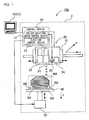
- Fig. 1 illustrates a block diagram of a three-dimensional shaping system 100 according to a first embodiment of the present invention.
- An example of application to a three-dimensional shaping apparatus in an ink-jet manner will be described as an example of the three-dimensional shaping apparatus.
- the three-dimensional shaping system 100 is adapted to eject shaping materials in a liquid state in an ink-jet manner, and then, cure and laminate the materials for fabricating an arbitrary shaped object.
- a model material MA configured to form a final shaped object and a supporting material SA configured to be shaped to support a protruding portion of the model material MA and to be finally removed therefrom are employed as such shaping materials.
- the three-dimensional shaping system 100 illustrated in Fig. 1 is constituted by a three-dimensional shaping apparatus 2, and a set-data creating apparatus 1 (a computer PC in Fig. 1 ) which transmits set data including shaping object data and shaping conditions to the three-dimensional shaping apparatus 2.
- the three-dimensional shaping apparatus 2 includes a control device 10, a head portion 20, and a shaping plate 40.
- the head portion 20 includes, as shaping-material ejection devices, model-material ejection nozzles 21 for ejecting the model material MA and supporting-material ejection nozzles 22 for ejecting the supporting material SA.
- the head portion 20 is further provided with a roller portion 25 for scraping off excess portions of these ejected shaping materials to thereby adapt the thickness of the uppermost layer of the shaped object at that time and smooth the surfaces of the shaping materials, and further, is provided with a curing device 24 for curing the shaping materials.
- an XY direction driving portion 31 and a Z-direction driving portion 32 as a horizontal driving device for reciprocating scanning in an X direction and also in a Y direction orthogonal to the X direction, and a vertical driving device for moving the positions of the head portion 20 and the shaping plate 40 with respect to each other in the height direction.
- the Y direction is the direction of arrangement of a plurality of orifices having model material ejection nozzles 21 and supporting material ejection nozzles
- the X direction is the direction that is orthogonal to the Y direction in the horizontal plane.
- the computer PC functions as the set-data creating apparatus 1.
- the CAD data is firstly converted into STL data (Stereo Lithography Data), for example, and then cross-section data is created by slicing the STL data into a plurality of thin cross-sectional parts, and then the slice data is transmitted to the three-dimensional shaping apparatus 2 collectively or on a slice-layer by slice-layer basis.
- STL data Stepo Lithography Data
- the shaping plate 40 in accordance with a determined attitude, on the shaping plate 40, of the model data designed through the three-dimensional CAD and the like (actually, the STL data resulting from the conversion), settings in relation to the positions for provision of the supporting material SA are performed in relation to portions or spaces in which the model made of the model material at this attitude is required to be supported, and based on these data, slice data corresponding to respective layers are created.
- the control device 10 takes the cross-section data from the computer PC and controls the head portion 20, the XY-direction driving portion 31, and the Z-direction driving portion 32 according to this data.
- the XY-direction driving portion 31 is operated, and also, the model-material ejection nozzles 21 and the supporting-material ejection nozzles 22 in the head portion 20 are caused to eject, as droplets, the model material MA and the supporting material SA as shaping materials, to suitable positions on the shaping plate 40, so that a cross-sectional shape is formed based on the cross-section data provided by the computer PC.
- the model material MA which is one of the shaping materials ejected on the shaping plate 40, is at least cured, so that the model material MA is changed from the liquid or fluid state to a solid, and thus, is cured.
- slice data may be produced on the side of the three-dimensional shaping apparatus 2, in that configuration, shaping parameters that must be determined by an operation such as the thickness of each slice must be sent from the computer PC side to the three-dimensional shaping apparatus 2.
- slice refers to a unit for laminating layers in the z direction of the shaped object, and the number of slices is equal to the value of the height divided by the laminated layer thickness.
- a minimum settable thickness is determined, according to the minimum unit amounts of materials which can be ejected from the respective ejection nozzles, variations caused by eccentricity of the roller in the roller portion 25 in the upward and downward directions, and the like.
- a value determined based on the aforementioned approach is defined as the minimum slice value, and thereafter, a user can finally determine the amount of each slice, in view of the required shaping accuracy and the required shaping speed, for example.
- the amount of each slice can be determined in such a way as to maintain a minimum necessary shaping accuracy.
- the shaping action for one slice data includes a series of steps of ejecting the shaping materials in a liquid or fluid state from the model-material ejection nozzles 21 and the supporting-material ejection nozzles 22 in an ink-jet manner at least in forward paths or rearward paths at least during reciprocating operations of the head portion 20 in the X direction (the main scanning direction of the head portion 20), further causing the roller portion 25 to operate to smooth the surfaces of the uncured shaped object at least in forward paths or rearward paths in a state where the shaped object resulting from the ejection onto the shaping plate 40 is in a fluid state, and then directing light with a specific wavelength from the curing device 24 to the smoothed surfaces of the shaped object to thereby cure the shaped object.
- the curing device 24 may be configured as a cooling or a heating device, and furthermore, the curing device may be omitted when applying natural curing.
- the maximum thickness which can be formed on the shaping plate through a single ejection from the model-material ejection nozzles 21 and the supporting material ejection nozzles 22 at least in a forward or rearward path is determined by a unit ejection amount which can maintain the cross-sectional shapes of ejected liquid droplets at substantially-circular shapes, after the liquid droplets have landed thereon.
- the shaping plate 40 can be raised and lowered by the Z-direction driving portion 32.
- the control device 10 controls the Z-direction driving portion 32 in such a way as to lower the shaping plate 40 by a distance corresponding to the thickness of the single slice. Further, operations same as the above are repeatedly performed, so that new slices are laminated on the upper side (the upper surface) of the first single slice. Thus, a plurality of thin slices is successively created and laminated as described above, thereby attaining shaping for a shaped object.
- a shaped object that includes an overhang shape is a shaped object that has a portion (overhang portion) that forms a slice of new model material on the upper surface of the portion on which a slice of model material that has already been formed is not present.
- control device 10 performs shaping of an overhang supporting portion SB based on the overhang-supporting-portion shape, at the same time as the shaping of the model material MA which is to form the final shaped object. More specifically, the supporting material SA, which is different from the model material MA, is ejected as droplets from the supporting-material ejection nozzles 22 to form the overhang supporting portion SB. After the shaping, the supporting material SA forming the overhang supporting portion SB is removed, thereby providing the target three-dimensional shaped object.
- the head portion 20 is moved by a head moving device 30 in the horizontal direction, namely in XY directions, as illustrated in a plan view in Fig. 3 .
- the head portion 20 is supported on an X direction displacing rail 43 that is a pair of guide mechanisms for the X direction (main scanning direction) respectively disposed in a vertical configuration in the figure.
- An X direction driving portion (not illustrated) is provided along one of the X direction displacing rails 43 on the base side that supports the head portion 20.
- a Y direction displacing rail 44 for displacing the head portion 20 in the Y direction (sub-scanning direction) is provided on a gate-shaped frame that places the head portion 20 on the X direction displacing rail 43.
- a driving portion (not illustrated) is provided for driving the head portion 20 along the Y direction displacing rail 44.
- the head portion 20 can be displaced in the X and the Y directions by the driving portion.
- the head portion 20 illustrated in the example in Fig. 4 is divided into an ejection head unit 20A provided with the ejection nozzle and a recovery and curing head unit 20B provided with the roller portion and a curing device.
- a rail guide 45 is provided between the ejection head unit 20A and the recovery and curing head unit 20B to enable passage of the Y direction displacing rail 44 that displaces the head portion 20.
- the head portion 20 as illustrated in the plan view in Fig. 3 undergoes reciprocating displacement in the Y direction along the Y direction displacing rail 44. Both ends of the Y direction displacing rail 44 are supported on the head moving device 30.
- the head moving device 30 undergoes reciprocating displacement in the X direction along the pair of X direction displacing rails 43 provided in parallel along the vertical dimension of the shaping plate 40 to straddle the shaping plate 40 in the vertical direction. In this manner, the head portion 20 can be displaced to an arbitrary position on the XY plane on the shaping plate.
- the shaping plate 40 is moved in the height direction, namely in the Z direction, by the plate raising/lowering device (the Z-direction driving portion 32), as illustrated in Fig. 1 . Accordingly, the heights of the head portion 20 and the shaping plate 40 can be changed with respect to each other, thereby enabling stereoscopic shaping.
- the head portion 20 is reciprocally operated in the X direction by the head moving device 30, and then, the model material MA and the supporting material SA are ejected from a plurality of orifices which are provided in the ejection nozzles 21 and 22 and extended in the Y direction. Further, as illustrated in Fig.
- the respective ejection nozzles 21 and 22 are reciprocally operated in the X direction at predetermined positions, thereafter the respective ejection nozzles 21 and 22 are shifted by a predetermined amount in the Y direction and then are reciprocally scanned at these positions.
- the model material MA and the supporting material SA are ejected to suitable positions based on the slice data. These operations are repeated to thereby create a shaped object corresponding to all the set shaping data.
- the plate raising/lowering device for raising and lowering the shaping plate 40 is employed as the Z-direction driving portion 32
- the present invention is not limited to this example, and as in a three-dimensional shaping apparatus 2' illustrated in Fig. 2 , it is also possible to employ a Z-direction driving portion 32' for moving the head portion in the Z direction, while the plate 40 is fixed in the height direction. Further, movement in the XY direction can be also attained by moving the shaping plate while fixing the head portion. It is possible to eliminate the necessity of shifting of the head portion 20 in the Y direction as described above, by making the width of the respective nozzles substantially equal to the width in the Y direction over which shaping can be performed on the shaping plate 40.
- the control device 10 controls the pattern of ejections of the shaping materials. That is, the control device 10 causes the shaping-material ejection device to eject the model material MA and the supporting material SA onto the shaping plate 40 at least in one of forward and rearward paths, during reciprocating scanning in the X direction, while reciprocally scanning the head portion 20 in a single direction, and further, causing the curing device 24 to cure the model material MA and the supporting material SA at least in one of the forward and rearward paths after the shaping-material ejecting device has ejected the shaping materials onto the shaping plate, thereby creating slices. Further, the control device 10 moves the positions of the shaping plate 40 and the head portion 20 with respect to each other in the height direction, and repeats laminating of slices to attain shaping.
- the smoothing of the surfaces of the shaping materials by the roller portion 25 is performed at least in one of forward and rearward paths, after the shaping-material ejection device has ejected the shaping materials onto the shaping plate, but before the curing device 24 cures the surfaces of the shaping materials.
- the control device 10 Through a single reciprocating scanning in the X direction, the control device 10 causes ejection of any one shaping material out of the model material MA and the supporting material SA, smoothing and removal of an excess portion on the surface of the shaping material with the roller portion 25, and further cures it with the curing device 24. Through the next and subsequent reciprocating scannings, the control device 10 causes ejection of the other shaping material which has not been ejected, smoothing of the surface of the shaping material, and curing.
- This series of processes is performed at least once for forming a single slice.
- the present invention includes repeating, a plurality of times, the aforementioned series of processes corresponding to slice data for a single layer, according to the shaping time period and the final model surface accuracy required by the user, for example.
- the surface of any one of the model material MA and the supporting material SA can be smoothed in an uncured state, cured, and thereafter, the other of the model material MA and the supporting material SA is ejected and separately cured.
- This offers the advantage of effective prevention of mixture of the model material MA and the supporting material SA at the boundary surface therebetween.
- model material MA is ejected and then supporting material SA is ejected.
- the supporting material may be ejected firstly followed by ejection of the model material.
- a method of separate ejection and curing of the model material and supporting material for shaping has been described in which either one of the shaping material is ejected first, and cured, and then the other shaping material is ejected and cured, there is no limitation to this method, and the model material and the supporting material may be ejected at the same time.
- a model material MA and a supporting material SA are employed, wherein the model material MA is to form a final shaped object, and the supporting material SA is to support protruding portions of the model material MA and to be removed finally.
- the curing device 24 is a light emitting device capable of emitting light containing at least a specific wavelength which causes the material of the model material MA to be cured in reaction thereto and, for example, the curing device 24 is an ultraviolet-ray emitting device such as an UV lamp.
- an UV light lamp it is possible to employ a halogen lamp, a mercury lamp, an LED and the like.
- the supporting material SA is also formed from a UV curing resin. In cases of employing an UV curing resin which can be cured by UV rays having the same wavelength, it is possible to employ the same ultraviolet-ray emitting device, thereby offering the advantage of utilization of a common light source.
- thermoplastic resin As the model material MA, it is possible to employ a thermoplastic resin. In this case, a cooling device is employed as the curing device 24. Further, in cases of employing thermoplastic resins as both the model material and the supporting material, when the model material has a melting point higher than the melting point of the supporting material, it is possible to remove the supporting material through melting by heating the shaped object after the completion of layer laminations to a temperature higher than the melting point of the supporting material and lower than the melting point of the model material, and then maintaining that temperature. Also, it is possible to employ a photo-curing resin as one of the model material and the supporting material, while employing a thermoplastic resin as the other of the model material and the supporting material.
- model material a material which can be cured by chemically reacting with a curing material.
- a liquid modifier agent into the model material as required in order to adjust injection characteristics such as viscosity and surface tension. Further, injection characteristics can be changed through temperature adjustments.
- Other exemplary model materials include UV photopolymers, epoxy resins, acrylic resins and urethanes.
- the same material as the model material described above may be used in relation to the supporting material SA.
- a material that facilitates final removal as the supporting material it is desirable to add a material that enables removal to a material that is similar to the model material. Consequently, more specifically, it is possible to employ a water-swellable gel, wax, a thermoplastic resin, a water-soluble material, a meltable material and the like.
- removing the supporting material SA it is possible to employ appropriate methods, for example, dynamic cleaning such as water solution, heating, chemical reactions and hydraulic cleaning, or separation utilizing thermal expansion differences through melting by irradiation of electromagnetic waves, according to the properties of the supporting material.
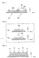
- Fig. 4 illustrates an example of the head portion 20 in the ink-jet type three-dimensional shaping apparatus.
- the head portion 20 illustrated in the figure is provided with dedicated ejection nozzles for individually ejecting a model material MA and a supporting material SA as shaping-material ejection devices. More specifically, the head portion 20 includes model-material ejection nozzles 21 for ejecting the model material MA and supporting-material ejection nozzles 22 for ejecting the supporting material SA, such that the materials are spaced apart from each other in parallel with each other.
- the ejection nozzles are both provided with two nozzle rows 23.
- the supporting-material ejection nozzles 22, the model-material ejection nozzles 21, the roller portion 25 and the curing device 24 are integrally provided in this order from the left side.
- Each of the ejection nozzles is adapted to eject an ink-type shaping material in a configuration of a piezoelectric-device type ink-jet printing head. Further, the shaping material is adjusted to have a viscosity enabling ejection from the ejection nozzles.
- the head portion 20 is adapted to eject the model material MA at first, and thereafter, eject the supporting material SA. Further, the head portion 20 is adapted to eject the shaping materials in forward paths (in the left-to-right direction in the figure), scrape off an excess resin with the roller portion 25 from the uppermost surface of the shaping material in the rearward path (from the right to the left in the figure), and after smoothing, to cure the smoothed resin with the curing device 24.
- the head portion 20 is further provided with the roller portion 25 for smoothing the surfaces of the shaping materials by pressing the surfaces of the ejected model material MA and the ejected supporting material SA in uncured states and by removing excess portions of the shaping materials.
- the configuration of operations of this roller portion 25 will be described with reference to the schematic view in Fig. 5 .
- a roller main body 26 is smoothing the surface of an ejected model material MA in an uncured state.
- the roller portion 25 includes the roller main body 26 as a rotational member, a blade 27 placed to protrude toward the surface of the roller main body 26, a bath 28 for storing the shaping material scraped off by the blade 27, and a suction pipe 29 for ejecting the shaping material stored in the bath 28.
- the roller main body 26 is rotatably supported and presses the uncured resin while rotating to thereby smooth the resin surface and remove and recover an excess portion.
- the roller main body 26 is rotated in the direction opposite from the direction of traveling of the head portion 20 (in the clockwise direction in Fig. 5 ) when scraping off an excess portion of resin with the roller main body 26 and thereby scrapes away the uncured shaping material.
- the blade 27 is disposed at a position behind the roller main body 26 relative to the direction of travel when the roller main body 26 abuts with the resin surface, and is fixed at an attitude inclined downwardly toward the bath 28.
- the bath (tub) 28 is disposed on the same side as the blade 27 relative to the roller main body 26, and is disposed below the blade 27.
- the suction pipe 29 is connected to a pump and is adapted to suction the shaping material stored in the bath 28 and then eject it.
- the roller main body 26 is made to have an outer shape with a diameter ⁇ of about 20 mm.
- the roller portion 25 is adapted to perform scraping when the head portion 20 travels in the right-to-left direction in the figure.
- the roller portion 25 does not come into contact with the shaping materials, and similarly, the curing device 24 does not perform irradiation from the light source.
- the roller portion 25 performs the aforementioned scraping operation, and also, the curing device 24 operates as a light source which emits light for curing at least the model material MA in the main scanning direction as a rearward path from the right to the left after the respective nozzles 21 and 22 are caused to eject the shaping materials at least, for example, in a forward path in the direction of left-to-right main scanning of the head portion 20 in the figure.
- the light source of the curing device 24 is disposed in front of the direction of travel of the model-material ejection nozzles 21 and the supporting-material ejection nozzles 22, and therefore even when the light source is lit, ejected resin in a fluid state before smoothing by the roller portion 25 is not irradiated. On the other hand, it is of course possible to turn off the light source of the curing device 24 at a timing other than that required positively. Furthermore, a configuration is possible in which a plurality of curing devices is provided.
- a first curing device and a second curing device may be provided as a curing device, and curing may be provisionally performed by the first curing device onto resin after ejection, and then further curing may be performed on resin by the second curing device.
- the provision of the curing device in a multistage configuration in this manner enables sufficient performance of the curing capacity of the resin.
- use of this configuration enables scraping off of excess resin by the roller portion after provisional curing using the first curing device when sufficient fluidity is still present in the resin even after application of the first curing device for provisional curing. That is to say, it is not necessary for all the curing devices to be disposed on the subsequent stage to the roller portion.
- the roller portion 25 is placed in front of the curing device 24, to the left in the figure.
- the uncured shaping materials are scraped off by the roller portion 25, and thereafter, the shaping materials are cured by the curing device 24. Due to this placement, the scraping and curing of the shaping materials can be performed along the same path, thereby offering the advantage of high efficiency processing.
- the basic concept of the disposition of the supporting-material ejection nozzle 22, the model-material ejection nozzle 21, the roller portion 25 and the curing device 24 along the X axis direction is as follows.
- the direction of forward travel in the main scanning direction of the head portion 20 is considered as a base, either one of the supporting-material ejection nozzle 22 and the model-material ejection nozzle 21 may be positioned in front of the other.
- roller portion 25 and the curing device 24 when the roller portion 25 and the curing device 24 perform a roller operation on the forward path, in the forward direction of travel, the roller portion 25 and the curing device 24 are disposed in order after the supporting-material ejection nozzle 22 and the model-material ejection nozzle 21, and when the roller operation is performed on the rearward path, the roller portion 25 and the curing device 24 may be disposed in order after the supporting-material ejection nozzle 22 and the model-material ejection nozzle 21 in the rearward path of travel.
- a method of irradiation with UV light is adopted in which, after ejecting resin from the head portion 20 to form a new uppermost layer, and after scraping off excess resin with the roller portion 25 in relation to the resin layer in the uppermost layer in an uncured state during shaping, at least the uppermost resin layer is cured by the curing device 24.
- a multistep configuration may be adopted in relation to the curing device as described above. For example, after ejecting resin from the head portion 20 to form a new uppermost layer, and after performing a single irradiation operation with the curing device 24 in relation to the uppermost resin layer including the excess resin layer, scraping of the excess resin layer is executed using the roller portion 25 on the uncured uppermost resin layer during shaping, and then the curing device 24 re-performs irradiation of UV light to cure at least the uppermost resin layer.
- the curing device 24 can perform the irradiation operation twice as described above by provision of a pair of curing devices in the transverse direction to sandwich the supporting-material ejection nozzle 22 and the model-material ejection nozzle 21 in the X direction in relation to the head portion 20, that is to say, in the main scanning direction of the head portion 20. Furthermore, in this case, in order to achieve a finally desired degree of curing of the resin by a combination of the first irradiation and the second irradiation, the resin after the first irradiation is not in a cured state, and is a fluid semi-cured state so that a scraping operation can be performed thereafter by the roller portion 25. Consequently, in this specification, the state of the uppermost layer before scraping with the roller portion 25 is an uncured state or a fluid state.
- the width of the roller portion 25 is formed to be less than the width of the model-material ejection nozzle 21 and the supporting-material ejection nozzle 22 provided on the shaping-material ejection device.
- Each of the nozzles includes a plurality of orifices for ejecting resin formed to be substantially parallel with the direction of sub-scanning that is orthogonal to the main scanning direction of the head portion 20 and are aligned with a predetermined interval.
- the width of each nozzle as described above means the distance between the orifices that are positioned on both end portions in the sub-scanning direction in each nozzle. That is to say, it means that the width of the roller portion 25 is less than the distance between orifices positioned on both end portions in the sub-scanning direction in each nozzle.
- the distance between orifices is defined on the premise that the respective orifices provided respectively in the model-material ejection nozzle 21 and the supporting-material ejection nozzle 22 are disposed in a linear configuration in relation to X direction relative to the head portion 20, that is to say, the main scanning direction of the head portion 20.
- model-material ejection nozzle 21 and the supporting-material ejection nozzle 22 are positioned and disposed relative to the head portion 20 so that the positions in the main scanning direction in which ejection is performed by each single orifice of the model-material ejection nozzle 21 all overlap with the positions in the main scanning direction in which ejection is performed by each single orifice of the supporting-material ejection nozzle 22.
- a plurality of model-material ejection nozzles 21, and in the figure, two and a plurality of supporting-material ejection nozzles 22 are used, the other of the model-material ejection nozzle 21 and the supporting-material ejection nozzle 22 is offset in relation to the sub-scanning direction relative to one of the model-material ejection nozzle 21 and the supporting-material ejection nozzle 22 and positioned and used in relation to the head portion 20.
- the basic objective of using a plurality of model-material ejection nozzles 21, and in the figure, two and a plurality of supporting-material ejection nozzles 22 is to improve the resolution in the Y direction of the model material or the supporting material by offsetting the position in the sub-scanning direction of the orifices provided on one of the model-material ejection nozzles 21 and the supporting-material ejection nozzles 22 relative to the position in the sub-scanning direction of the orifices provided on the other of the model-material ejection nozzles 21 and the supporting-material ejection nozzles 22.
- the meaning of the width of the roller portion 25 in the present invention being less than the width of the model-material ejection nozzle 21 and the width of the supporting-material ejection nozzle 22 provided on the shaping-material ejection device is as follows.
- the width of the model-material ejection nozzle 21 when a plurality of model-material ejection nozzles 21 is disposed in an offset configuration in relation to the sub-scanning direction means that the width of the roller portion 25 is less than the distance from the offset position disposed on the outermost side on one end portion in the sub-scanning direction of the plurality of model-material ejection nozzles 21 to the offset position disposed on the outermost side on the other end portion in the sub-scanning direction.
- This configuration is the same also in relation to the plurality of supporting-material ejection nozzles 22 adopted in the same system.
- this system is premised on a configuration in which the model-material ejection nozzles 21 and the supporting-material ejection nozzles 22 are positioned and disposed relative to the head portion 20 so that the positions in the main scanning direction in which ejection is performed by each single orifice of the model-material ejection nozzle 21 all overlap with the positions in the main scanning direction in which ejection is performed by each single orifice of the supporting-material ejection nozzle 22.
- the width of the roller portion 25 described above denotes the axial direction of the roller portion 25, that is to say, the substantial width used when scraping off excess resin on the roller surface of the roller portion 25 in the sub-scanning direction, and even when the apparent width is larger than the width of the model-material ejection nozzle 21 and the width of the supporting-material ejection nozzle 22, the width of the roller that is the original function as the roller portion and performs the scraping function may be less than the width of the model-material ejection nozzle 21 and the width of the supporting-material ejection nozzle 22.
- the roller diameter may be varied by provision of a step from the roller portion formed on the end portion of the roller that substantially does not function to scrape off excess resin to the roller portion that substantially scrapes off excess resin, or the diameter of the roller portion may be continuously varied gradually from the roller portion formed on the end portion of the roller that substantially does not function to scrape off excess resin toward the roller portion that substantially scrapes off excess resin.
- Fig. 6 shows an example of the bottom view of the head portion 20.
- the model-material ejection nozzle 21 and the supporting-material ejection nozzle 22 are disposed to respectively offset two rows of ejection nozzles.
- a width D1 of the model-material ejection nozzle 21 and a width D2 of the supporting-material ejection nozzle 22 are substantially equal and the offset amount is also substantially equal. Therefore, the ejection width DN of all ejection nozzles is substantially equal in both the model-material ejection nozzles 21 and the supporting-material ejection nozzles 22.
- the width DR of the roller portion 25 is less than the ejection width DN of the ejection nozzle.
- the width of the roller portion 25 By reducing the width of the roller portion 25 to be less than the ejection width DN, as illustrated in Fig. 7 even when the same layer (slice) is shaped into a plurality of sections (the sections R1, R2 in the example illustrated in Fig. 7 ), when the roller portion 25 presses the right-side section R2, no contact is made with the already shaped section (the left-side section R1 in Fig. 7 ), and therefore a large surface area shaping operation is possible with high accuracy. Since there is no erroneous recovery of resin after curing, a state in which the suction pipe is blocked can be avoided.
- the amount of adjustment of the shaking and tilt of the roller portion is preferably less than or equal to the thickness of one slice, and therefore difficulties associated with adjustments during the preparation and mounting of the roller portion can be reduced.
- the width of the roller portion 25 is formed to be less than the distance between the orifices on both ends of the model-material ejection nozzle and the supporting-material ejection nozzle by one half of the orifice alignment pitch (0.5 mm). For example, when the orifice alignment pitch is 1 mm, the width of the roller portion 25 is formed to be respectively 0.5mm less on both ends than the distance between the orifices that are positioned on both ends of the model-material ejection nozzle and the supporting-material ejection nozzle.
- a configuration in which the width of the roller portion 25 is less than the ejection width means that there is a portion in which resin cannot be recovered by the roller portion 25 such as the portion enclosed by the broken line as illustrated in Fig. 7 .
- the resin is not maintained from the liquid state to the state illustrated in Fig. 8(a) , and as a result of not maintaining the shape due to its weight, sags as illustrated in Fig. 8(b) .
- shaping is performed that is substantially the same as when all is recovered by the roller portion 25, and there is almost no problem in practice.
- the thickness of the excess resin that is scraped from the uppermost surface of the shaped body is a thickness of for example several tens of ⁇ m, and preferably no more than 50 ⁇ m. Therefore it can be stated that there is no problem in practice even when the height of the resin in the scraping residual portion is of a similar height.
- printing can be performed by offsetting in the sub-scanning direction from the resin ejection position in the previous sub-scanning direction. In this manner, the position at which the roller portion 25 is not applied in relation to each slice layer is varied, and the effect of residual resin that is not recovered does not accumulate and therefore is uniformly suppressed.
- the width of the roller portion 25 is preferably formed to be less than the width of the total set of the plurality of rows of the model-material ejection nozzles 21. In this manner, the resolution can be improved by disposing the model-material ejection nozzles 21 with an offset, the width of the roller portion 25 can be reduced in relation to the model-material ejection nozzles 21 disposed in an offset configuration, and even when the same slice is shaped by division into a plurality of sections, the roller portion 25 does not make contact with the shaped body, and high accuracy shaping can be executed.
- the effect of unrecovered residual resin can be prevented from accumulating by varying the position of application of the roller portion in relation to each slice. That is to say, a state in which only the interface portion is higher can be suppressed by varying the position of the border between sections in each slice.
- the ejection position for resin is offset by the control device 10 so that the border P2 of the next step is positioned between the borders P1 of the sections in which ejection was performed in the previous step.
- the control device 10 of the three-dimensional shaping apparatus illustrated in Fig. 1 and Fig. 2 includes a roller rotation speed control device 12.
- the roller rotation speed control device 12 varies the rotation speed of the roller main body 26 in response to the physical characteristics of the model material MA and the supporting material SA ejected from each ejection nozzle when performing separate recovery of the model material MA and the supporting material SA with the roller main body 26.
- the respective resins as the model material MA and the supporting material SA are ejected separately, are recovered separately, and cured separately, and not at the same time.
- the rotation speed of the roller main body 26 can be varied in response to the physical characteristics of each resin when recovering the respective resins.
- each resin includes the surface tension and the viscosity of the resin on the uppermost surface of the shaped body and in proximity thereto prior to scraping off with the roller portion 26.
- the actual optimal rotation speed of the roller portion is determined in consideration of shaping condition parameters such as the displacement speed in the X direction of the head portion, the resin ejection amount per unit time from the head portion, and the like in addition to settings based on verification of the basic optimal rotation speed in relation to the surface tension and the viscosity of the resin on the uppermost surface of the shaped body and in proximity thereto obtained by actual experimentation in relation to the actual model material and supporting material used in shaping.
- a rotation speed determination table for the roller portion can be prepared based on this information, and stored. In this case, the rotation speed determination table for the roller portion may be stored either in the set-data creating apparatus 1 or the three-dimensional shaping apparatus 2.
- the table includes separate values (2 values) for the rotation speed of the roller main body 26 in relation to model material removal and supporting material removal, and therefore enables recovery of resin at a rotation speed that is adapted to the respective resins, and that reduces mixing at the boundary of the model material MA and the supporting material SA.
- the roller rotation speed control device 12 is incorporated in the control device 10.
- This type of control device 10 can be configured as an MPU, or the like. However, it is needless to say that the roller rotation speed control device and the control device may be provided separately.
- step S1101 As illustrated in Fig. 10(a) , the supporting material SA is ejected.
- step S1102 the roller main body 26 is rotated and pressed at a rotation speed a that is adapted to the supporting material SA as illustrated in Fig. 10(b) .
- step S1103 the model material MA is ejected as illustrated in Fig. 10(c) .
- step S1104 the roller main body 26 is rotated and pressed at a rotation speed b that is adapted to the model material MA as illustrated in Fig.
- the ejection amount per unit time can be suitably determined from the point of view of shaping speed or shaping accuracy.
- the shaping speed can be increased by performing shaping on the basis of increasing the ejection amount per unit time of the supporting material relative to the model material.
- the rotation speed of the roller portion 25 preferably has a suitable setting when scraping the model material and the supporting material based on the shaping accuracy and the shaping speed.
- Evaluation experiments for confirming the efficacy of the above embodiment were performed by varying the rotation speed (rotation number) of the roller main body 26 in relation to the shaped object illustrated in Fig. 12 and comparing the shaped object after removal of the supporting material.
- the results are illustrated in Table 1 and Table 2.
- Table 1 illustrates the state in which the rotation number is varied between 469 to 1125 pps for the main purpose of recovery of the model material MA
- Table 2 illustrates the state in which the rotation number is varied between 375 to 1125 pps for the main purpose of recovery of the supporting material SA.
- the viscosity of the model material MA used in this experiment is 45 mPa.s, and the surface tension is 30 mM/m.
- the viscosity of the supporting material SA is 80 mPa.s, and the surface tension is 34 mM/m.
- the shaped object resulting from the shaping operation has four upright separate thin walls having a thickness of several hundred ⁇ m.
- the supporting material SA is provided in the periphery thereof.
- Table 1 and Table 2 The results of shaping by varying the rotation number of the roller main body 26 in relation to this type of thin wall are illustrated in Table 1 and Table 2. In these tables, those thin walls that are upright are denoted by O, those thin walls that are slightly curved are denoted by ⁇ , and those thin walls that are greatly deformed or not shaped are denoted by X.
- Mixing at the boundary of the model material and the supporting material of the shaped object can be reduced by recovering the two types of resin comprising the model material and the supporting material at different times by optimizing the rotation speed of the roller main body during recovery in accordance with the respective resins.
- separate curing of the model material and the supporting material enables varying of the rotation speed of the roller main body when recovering the model material and the supporting material, and a high quality shaped object can be obtained in which mixing at the resin interface is suppressed by recovering the excess resin portion in response to the physical characteristics of each resin.
- the control device 10 illustrated in Fig. 1 and Fig. 2 includes an ejection control device 13.
- the ejection control device 13 controls the shaping-material ejection device to not eject shaping material after curing for a predetermined number of slices when changing the type of shaping material ejected from the shaping-material ejection device from one to the other of the model material MA and the supporting material SA.
- the ejection control device 13 functions as a hollow portion creating device for creating a hollow portion ES by removing shaping material corresponding to a predetermined number of slices after switching at a position at which the type of shaping material ejected from the shaping-material ejection device changes in the vertical direction of the shaped object.
- a hollow portion corresponding to removed slices is produced in the height direction by removing a predetermined number of slices that are laminated immediately after the boundary surface between different shaping materials such as the model material MA and the supporting material SA so that the roller portion does not make contact with the surface of the shaping material, and therefore it is possible to prevent recovery of cured shaping material with the roller portion.
- the roller portion 25 as illustrated in Fig. 33 may make contact with cured resin that it should not make contact with as a result of a vibration in the driving portion or the accuracy of mechanical components such as the roller portion 25 when shaping by recovering the excess portion of resin as illustrated in Fig. 32 by use of a recovery mechanism using the roller portion 25.
- peeling does not result when the layer of cured resin has become integral with the cured resin of the same type to form a thick body.
- problems may occur such as the portion making contact may be peeled by the roller portion 25 to block the liquid waste passage, the whole layer may be peeled, and creasing may result on the surface.
- the present embodiment increases the operation characteristics for the removal operation of the supporting material by weakening the bonding between the resins, and in proximity to the bonding between different resins, that is to say, when the layer of the same type is thin, the converse problem above is solved by a configuration in which the roller portion 25 is not applied. More specifically, the resin is configured with a height difference so that the roller portion does not make contact with thin resin layers. For this reason, the ejection control device 13 as illustrated in the block figure in Fig. 1 and Fig. 2 produces ejection data by application of an erroneous recovery prevention process to the shaped object data.
- the shaped object includes a hollow portion ES in which the ejection amount is reduced or no ejection of the first shaping material or the second shaping material from the shaping-material ejection device is performed in relation to a slice at the boundary surface between the different types of shaping material at which the model material MA or the supporting material SA changes from one shaping material to the other shaping material with respect to the height direction during lamination.
- the control device 10 detects the presence of the hollow portion ES in the slice of the shaped object, and performs control to not eject shaping material or to reduce the ejection amount from the shaping-material ejection device at the position corresponding to the hollow portion ES.
- the control device 10 completes shaping of the slice by executing control to not eject shaping material or reduce the ejection amount from the shaping-material ejection device at the position corresponding to the hollow portion ES when a hollow portion ES is included in the slice of the shaped object, and then uses the vertical driving device to switch the relative position in the height direction of the head portion 20 and the shaping plate 40, and when shaping the slice in the next layer, the uppermost layer of the second shaping material ejected at the position corresponding to the hollow portion ES is separated from the roller portion 25.
- the control device 10 controls the shaping-material ejection device and the vertical driving device so that when shaping a slice after the next layer, the uppermost layer of the second shaping material ejected at the position corresponding to the hollow portion ES is brought into contact with the roller portion 25, and the excess portion of the second shaping material ejected at that position is scraped off with the roller portion 25.
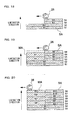
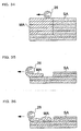
- Fig. 13(a) illustrates the shaping of a shaped object.
- Fig. 13(b) illustrates the configuration in which a hollow portion ES is formed by removing a slice corresponding to several layers as described above.
- two layers of model material are scraped off at the boundary surface of switching from supporting material SA to model material MA to thereby form a hollow portion ES.
- the hollow portion ES is formed, the subsequently laminated layers are embedded with resin from above the hollow portion ES.
- the sequence of forming the shaped object in Fig. 13(b) including the hollow portion ES will be described based on the schematic sectional figures in Fig. 14 to Fig. 17 .
- the model material MA and the supporting material SA are simultaneously shaped.
- the model material MA and the supporting material SA are ejected in a single scanning by the head portion.
- Data process is performed in relation to the shaped object data as illustrated in Fig. 14(a) , and the respective layers (slices S1 to 6) are shaped in the sequence illustrated in Fig. 14(b) .
- the respective layers are assumed to be shaped by a single slice portion by a single reciprocating motion of the head portion.
- the model material MA and the supporting material SA are laminated sequentially in each slice in the order illustrated in Fig. 14(a) . More specifically, in a slice S1, the block B1 of supporting material SA is ejected and cured, and after shaping of the supporting material layer (block B1), in a slice S2, the supporting material layer (block B2) is shaped onto the upper surface of the supporting material layer (block B1). Then, in a slice S3, the model material layer MA (block B3) and the supporting material SA (block B3') are respectively ejected and cured on the upper surface of the supporting material layer B2.
- a model material layer (block B4) is ejected and cured on the upper surface of the model material layer MA (block B3), and a supporting material layer SA of the block B4' is ejected and cured on the upper surface of the supporting material layer SA of the block B3'. Thereafter, the same operation is repeated, to thereby shape the same slices to a block B6 for the model material layer and a block B6' for the supporting material layer.
- shaping is executed to remove two layers of model material MA.
- the slices 1 and 2 are shaped as illustrated in Fig. 14(a) , and in relation to the slices S3 and S4, model material is not ejected, and only supporting material SA is ejected and shaped (blocks B3, B4). In this configuration, only supporting material SA is shaped as illustrated in Fig. 14 .
- model material MA is ejected for the first time in the shaping of the slice S5 (block B5).
- Supporting material SA (block B5') is also ejected in the slice 5.
- the height of the roller main body during the shaping of slice S5 corresponds to the position on the upper surface of the block B5' in Fig. 15 . That position is higher than the upper surface of the block B5, and therefore even when the roller main body 26 is rotated at that height, no contact is made with the surface of the block B5. That is to say, the roller main body 26 at the height of the block B5' does not recover model material MA at the position on the block B5.
- the block B5 that is not subjected to recovery of excess resin is shaped to be slightly thicker than other block.
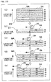
- the head portion is displaced to the height of the slice S6 with the vertical driving device and model material MA (block B6) and supporting material SA (block B6') are ejected.
- the height of the roller main body 26 is also positioned on the upper surface of the block B6' as illustrated by the broken line in Fig. 16 , and the roller main body 26 does not reach the surface of model material MA and therefore model material MA is not recovered.
- the model material MA and the supporting material SA are successively shaped.
- the height of the roller main body 26 corresponds to a position on the upper surface of the block B8' in Fig. 17 , and therefore the model material (block B8) comes into contact with the roller main body 26 and the excess resin portion is recovered.
- the ejected resin for the model material MA includes the excess portion, the thickness is higher than the thickness of the slice of laminated supporting material SA, and the difference between the model material MA and the supporting material SA gradually decreases as the slices are laminated.
- the roller main body 26 makes contact with the model material MA, and recovery of the excess resin portion commences.
- the supporting material SA is laminated in 6 slices S3 to S8 to thereby compensate for the height difference resulting from scraping off two layers of model material MA.
- the model material MA is already laminated in four layers (blocks B5 to B8), and has a sufficient thickness, even when making contact with the roller main body 26, only the upper layer portion is peeled and removed.
- the boundary surface between the model material MA has a sufficient bonding strength since it is the same type of resin.
- the present invention is not limited in this respect, and can also be applied to separate shaping in which the model material and the supporting material are shaped respectively separately.
- Separate shaping is adopted in the second embodiment described below, and the lamination sequence of shaping material in separate shaping will be described making reference to Fig. 18 to Fig. 21 .
- the model material MA and the supporting material SA are shaped using separate shaping, and data processing is performed in relation to the shaping data illustrated in Fig. 21(a) to thereby shape each layer (slices S1 to S6) in the order illustrated in Fig. 21(b) .
- the respective layers are assumed to be shaped by a single slice portion by a single reciprocating motion of the head portion.
- the model material MA and the supporting material SA are laminated sequentially in each slice in the order illustrated in Fig. 21(a) . More specifically, in a slice S1, the supporting material SA is ejected and cured, and after shaping of the supporting material (block B1), in a slice S2, a new supporting material layer (block B2) is shaped onto the upper surface of the block B1. Then, in a slice S3, only model material MA is ejected and cured onto the upper surface of the supporting material layer B2 (block B3). Then only supporting material SA. is ejected and cured on the upper surface of the supporting material layer B2 (block B4).
- shaping is executed to remove two layers of model material MA.
- the slices 1 and 2 are shaped in the same manner as illustrated in Fig. 21(a) , and in relation to the slices 3 and 4, model material is not ejected, and only supporting material SA is ejected and shaped (blocks B3, B4). In this configuration, only supporting material SA is shaped as illustrated in Fig. 18 .
- model material MA is ejected and cured for the first time in the shaping of the slice S5 (block B5).
- the height of the roller main body during the shaping of slice S5 corresponds to the position on the upper surface of the block B6 in Fig. 21(b) . That position is higher than the upper surface of the block B5, and therefore even when the roller main body is rotated at that height, no contact is made with the surface of the block B5. That is to say, the roller main body does not recover model material MA at the position on the block B5.
- the block B5 that is not subjected to recovery of excess resin is shaped to be slightly thicker than other blocks.
- the supporting material SA (block B6) is shaped at the same height (slice S5). Thereafter, the head portion is displaced to the height of the slice S6 with the vertical driving device and model material MA (block B7) is ejected. At this time, the height of the roller main body is also positioned on the upper surface of the block B8 as illustrated by the broken line in Fig. 19 , the roller main body does not reach the surface of model material MA and therefore model material MA is not recovered.
- the supporting material SA (block B8) is shaped at the same height (slice S6).
- the model material MA and the supporting material SA are successively shaped.
- the height of the roller main body corresponds to a position on the upper surface of the block B12 in Fig. 20 , and therefore the model material MA comes into contact with the roller main body and the excess resin portion is recovered.
- the ejected resin for the model material MA includes the excess portion, the thickness is higher than the thickness of the laminated slices, and the difference between the model material MA and the supporting material SA gradually decreases as the slices are laminated.
- the roller main body makes contact with the model material MA, and recovery of the excess resin portion commences.
- the supporting material SA is laminated in six slices S3 to S8 to thereby compensate for the height difference resulting from scraping off two layers of model material MA.
- the model material MA is already laminated in four layers, and has a sufficient thickness, even when making contact with the roller main body, only the upper layer portion is peeled and removed.
- the boundary surface between the model material MA has a sufficient bonding strength since it is the same type of resin.
- the provision of a hollow portion enabled a configuration in which the roller does not make contact with at least one layer of shaping material that is initially ejected at the boundary surface at which the type of resin changes with respect to a direction of height.
- the control of the amount of shaping material ejected at the boundary surface at which the resin type changes prevents the roller from coming into contact with the shaping material in the layer formed immediately thereafter that is ejected at the boundary.
- the control of the ejection amount of resin is enabled by control of an ejection nozzle by the voltage applied to a piezoelectric element
- the variation of the voltage value, the pulse width, the frequency or the like of the voltage that is applied to the piezoelectric element enables adjustment of the resin amount that is ejected per unit time.
- This control for example is realized by the ejection control device 13.
- the method of simultaneous shaping while controlling the ejection in this manner is illustrated as a third embodiment in Fig. 22(a) to Fig. 22(d) .
- the ejection amount of model material MA in the slice S4 is limited to thereby form a hollow portion ES'.
- the hollow portion ES' is not formed by a block in which shaping material is completely not ejected, but rather, the ejection amount of shaping material is reduced, and the volume of the hollow portion ES' is slightly smaller than the example of the hollow portion ES described above.
- the supporting material SA is successively ejected and cured. Then in the ejection for the slice S4 as illustrated in Fig. 22(b) , the amount of model material MA that is ejected in the block B3 is limited to be thereby less than a normal slice (block B4').
- the supporting material SA ejected in the block B3 is the same as a normal slice. In this configuration, when the roller main body 26 is applied, the excess portion of resin is recovered in relation to the block B4 of supporting material SA and on the other hand, since the roller main body 26 does not come into contact with the block B4' of the model material MA, overall peeling of the block B4' can be avoided.
- the lamination of the slice S5 as illustrated in Fig. 22(c) is such that the model material MA is ejected in a normal amount onto the block B4' (block B5'), or the supporting material SA is ejected in the same manner onto the block B4 (block B5).
- the roller main body 26 is applied to the block B5, the roller body 26 does not make contact with the uncured block B5' in that configuration, and therefore it is possible to avoid a situation in which the whole of the model material layer formed from the blocks B4' and B5' is scraped off.
- the block B5' is laminated with a thickness that is higher than a normal slice, and thereby reduces the height difference with the block B5 of supporting material SA.
- the lamination of the slice S6 as illustrated in Fig. 22(d) is such that the model material MA is ejected in a normal amount onto the block B5', and the supporting material SA is ejected in the same manner onto the block B5, and the blocks B6' and B6 are laminated.
- the position of scraping with the roller main body 26 corresponds to the upper surface position of the block B6, and excess resin is scraped from the supporting material SA.
- the upper surface of the block B6' in which model material MA is ejected substantially corresponds with the upper surface position of the block B6.
- the hollow portion ES' is not limited to complete stopping of ejection into a slice and may be formed by controlling the ejection amount. In other words, even a hollow portion ES' that is formed by reducing the ejection amount is sufficient if the resin in an uncured or flowing state is separated to prevent contact with the roller main body. Therefore, a block in which the ejection amount is reduced as described above is included within a hollow portion within the meaning of the present invention.
- the invention is not limited in this regard, and naturally, the same effect can be obtained by removal of the supporting material. That is to say, there is no limitation in relation to control to not eject model material, and ejection of model material may be maintained while controlling ejection of supporting material to thereby obtain the same effect.
- control is executed to not eject a one-layer amount of supporting material SA on the lower side.
- the shaping accuracy is reduced at least in relation to one layer in the height direction due to the fact that the supporting material is scraped away and the model material laminated thereon is cured to a greater degree than at the original position.
- the actual thickness of one slice is extremely small, the resulting reduction in the shaping accuracy can be ignored, or almost no reduction in shaping accuracy is produced even if the hollow portion includes a plurality of layers.
- FIG. 24(a) An example in which the hollow portion is provided on the supporting material side is illustrated as a fourth embodiment in Fig. 24(a) to (e) .
- supporting material that is positioned in the slice S3 is removed to form a hollow portion ES in the shaping material that makes contact with the boundary surface of switching from the supporting material to the model material.
- the supporting material and the model material are ejected and cured by simultaneous shaping.
- the supporting material SA is laminated (block B1, B2).
- slice S3 although supporting material SA is ejected (block B3), at the position of contact with the model material MA laminated on the upper surface, supporting material that should normally be ejected is not ejected, and thereby forms a hollow portion ES.
- the excess portion of resin is scraped off only in relation to upper surface of the block B3 (the position illustrated by the broken line in the figure).
- model material MA and supporting material SA are ejected as illustrated in Fig. 24(c) to thereby respectively laminate the block B4" and B4.
- the excess portion of resin is scraped off at the upper surface position of the block B4 as illustrated by the broken line in the figure.
- the upper surface of the block B4" into which model material MA is ejected is positioned lower than the position of scraping with the roller main body 26, and therefore the model material MA does not come into contact with the roller main body 26 and scraping does not occur.
- the block B4" is laminated in a thick configuration and reduces the height difference of the uppermost layer of the supporting material SA and the model material MA.
- the block B5" and B5 are respectively laminated.
- the roller main body 26 is applied, although the excess portion of resin is scraped off at the upper surface position of the block B5 as illustrated by the broken line in the figure, since the upper surface of the block B5" into which model material MA is ejected is still positioned lower than the position of scraping with the roller main body 26, the model material MA is not scraped off by the roller main body 26.
- the block B5" retains a thick laminated configuration and further reduces the height difference.
- the three layers of model material MA including the excess portion substantially correspond to the four layers of supporting material SA after removal of the excess portion.
- the number of slice layers forming the thickness of the hollow portion ES is determined in relation to how many layers of shaping material are peeled by the roller main body that is used or in response to the type of shaping material, the viscosity, the bonding force at the boundary surface between the model material and the supporting material, and the like.
- the hollow portion may be provided, and on the other hand, the ejection amount may be limited.
- a sufficient hollow portion ES must be provided to enable at least no contact of the roller main body with the first slice layer ejected initially onto the boundary surface between different shaping materials, and preferably, no contact of the roller main body with a plurality of slice layers ejected after the boundary surface as in the above embodiment.
- An example in which the hollow portion is separate from the boundary surface between different shaping materials in this manner is described in Fig. 25(a) to (e) as a fifth embodiment.
- a hollow portion ES is formed in which one layer of supporting material is removed at a position separated by one layer below the boundary surface between different shaping materials at which there is a switch from the supporting material to the model material.
- the supporting material and the model material are ejected and cured using simultaneous shaping.
- the supporting material SA is laminated (block B1).
- supporting material SA is ejected (block B2), at the position of separation by one slice from the boundary surface between different shaping materials, supporting material is not ejected, and thereby a hollow portion ES is formed.
- the excess portion of resin is scraped from the upper surface of the block B2 (the position illustrated by the broken line in the figure).
- the supporting material SA is ejected as illustrated in Fig. 25(c) to thereby respectively laminate the block B3' and B3.
- the excess portion of the supporting material SA is scraped off at the upper surface position of the block B3 as illustrated by the broken line in the figure. Since the supporting material SA in the block B3' is in a lower position than the scraping position of the roller main body 26 on the upper surface of the block B3', no contact is made with the roller main body 26, and no scraping occurs.
- the block B3' is laminated thickly, and the height difference on the uppermost surface of the blocks B3' and B3 is reduced.
- the block B4' and B4 are respectively laminated.
- the roller main body 26 is applied, although the excess portion of resin is scraped off at the upper surface position of the block B4 as illustrated by the broken line in the figure, since the upper surface of the block B4' into which model material MA is ejected is still positioned lower than the position of scraping with the roller main body 26, the model material MA is not scraped by the roller main body 26.
- the block B4' retains a thick laminated configuration and further reduces the height difference.
- a configuration is enabled in which the roller main body 26 does not make contact even at the boundary surface between different shaping materials at which there is a change from one resin to the other resin. In this manner, the advantage is obtained that superior surface finishing of the shaped object is enabled.
- the fifth embodiment is configured to prevent contact of the roller main body 26 with the resin surface at the different-type boundary surface by providing a hollow portion ES below the boundary surface therebetween so that the roller main body does not make contact with the boundary surface therebetween at which the resin switches.
- the resin surface is flat and smooth prior to contact with the roller main body 26, and therefore shaping accuracy is maintained without performing recovery of excess resin by separation from the roller main body 26 at the switching boundary and a superior surface configuration function is realized that improves the surface configuration of the shaped object.
- the hollow portion was provided on the supporting material side since the supporting material is positioned below the boundary surface between different shaping materials.
- the same effect is obtained in an example in which the supporting material is positioned below the boundary surface between different shaping materials and not the model material, that is to say, the hollow portion is configured on the model material side at the switching boundary surface from the model material to the supporting material and not the boundary surface of switching from the supporting material to the model material as illustrated in Fig. 25 .
- simultaneous shaping was performed, the same effect can be obtained in relation to separate shaping.
- the position of change of type of resin in the lamination direction of the resin is mixed with the position of continuation of the same resin in the same slice layer.
- a slice layer that includes both a position of change from the supporting material to the model material in the direction of lamination and a position of continuous supporting material.
- the same slice layer may include a position of continuous model material and a position of change from the model material to the supporting material depending on the shape of the shaped object.
- a position of continuous ejection in the lamination direction of one resin of the model material and the supporting material and a position of change from the first resin to the second resin or from the second resin to the first resin are included in the same slice layer (the slice layer in the figure illustrates only a portion, and actually, the slice layer extends in a horizontal configuration, and is laminated in a variety of patterns in relation to each position that extends in the horizontal configuration).
- the hollow portion ES is formed only in a portion in the same slice layer, and the layer of the same resin has a continuous configuration without formation of the hollow portion ES at a position at which the same resin layer continues.
- a configuration may also be considered in relation to the same slice layer in which only a position at which the first resin changes to the second resin is present in the lamination direction of the resin and a position at which the same resin layer is continuous is not present.
- a layer of supporting material is formed corresponding to at least one slice layer on the shaping plate to facilitate removal of the shaped object from the shaping plate 40.
- a slice layer including model material is formed on the layer of supporting material. When there is no position at which the supporting material is ejected onto the layer of supporting material, a slice layer will be shaped which includes only positions of change from the supporting material to the model material.
- slice layer is only configured by the hollow portion ES, no shaping material is ejected, and only the relative distance in relation to the height direction of the shaping plate 40 and the ejection nozzle is changed at least once and controlled so that the roller main body does not make contact with the slice layer that is formed initially at least by ejection of model material.
- a separate shaped object may be shaped on one shaped object.
- the boundary surface between the model material and the supporting material is not limited to one surface in the direction of lamination, and may exist in a plurality of surfaces.
- supporting material is interposed to facilitate separation of the objects.
- the hollow portion ES is provided again in the model material, and a plurality of hollow portions may be provided in the direction of lamination.
- the number of layers of supporting material that are removed is set depending on the thickness of one slice, the assumed vibration amount or manufacturing dimensions of the roller main body, the bonding strength of the supporting material or the model material, or the like. For example, this may be 1 to 4 layers, preferably 1 to 3 layers, and still more preferably 2 to 3 layers.
- This type of shaped object can be processed by modifying the designated shaped object data.
- the shaped object data can be prepared in the ejection control device 13 to produce ejection data so that in a slice in which there is a switching between a resin and the shaping material laminated in a lower layer, one or more layers are removed in a block of the portion of the switched shaping material.
- shaped object data is acquired.
- the shaped object data for example is input into an STL file, or the like.
- the section of supporting material required for shaping of the shaped object is calculated.
- necessary correction processing is performed.
- processing to prevent erroneous recovery is performed.
- the ejection control device 13 extracts the boundary surface of switching of the shaping material between slices as described above to one of the supporting material SA and the model material MA, and removes only a predetermined number of layers of shaping material that is laminated onto the upper surface of the boundary surface.
- a control unit controls the shaped object ejection device of the head portion in accordance with the ejection data created in this above manner. In this manner, ejection of shaping material is controlled to not eject a resin that differs from the switching position of the resin for one or more layers.
- ejection data for the provision of a hollow portion ES formed from two layers in the model material MA as illustrated in Fig. 13(b) will be considered.
- the logical product is acquired as model data for a total of three layers being the layer that is shaped, and the layer one layer below and the layer two layers below.
- an ejection section is calculated using the logical product on the data for the three layers (in the box in the figure) calculated for the slice S3.
- the calculation of the logical product is performed by ascribing a value of 1 to dots for ejection of model material MA and a value of 0 to other dots.
- a slice S'3 after calculation is a slice of dot 0, that is to say, a slice in which model material MA is not ejected as illustrated in Fig. 27(b) .
- the data for the slice S4 is used in relation to the logical product on the data for the three layers including the slice S4 (the box in the figure) as illustrated in Fig. 28(a) , and therefore the slice S'4 after the calculation is a slice of dot 0, that is to say, a slice in which model material MA is not ejected as illustrated in Fig. 28(b) .
- the data for the slice S5 is used in relation to the logical product on the data for the three layers including the slice S5 (the box in the figure) as illustrated in Fig. 29(a) , and therefore the slice S'5 after the calculation is a slice of dot 1, that is to say, a slice in which model material MA is ejected as illustrated in Fig. 29(b) .
- a boundary surface of change from one type of shaping material to another type of shaping material in relation to the direction of lamination is extracted from the shaped object data, and shaping is controlled so that the roller does not make contact with the boundary surface of change of resin type by creating ejection data for the provision of a predetermined number of layers in a layer in which the ejection amount is reduced or so that one of the resins is not ejected in contact with the extracted boundary surface or at least in a position separated by a predetermined number of layers.
- the creation of such ejection data is executed in the set-data creating apparatus 1.
- the set-data creating apparatus 1 creates ejection data including the hollow portion ES based on the shaped object data, and sends the data to the three-dimensional shaping apparatus 100.
- the creation of the ejection data can be configured for execution in the three-dimensional shaping apparatus 100 based on the shaped object data received from the set-data creating apparatus 1.
- an ejection data storage device is provided for storage of ejection data recording the ejection pattern for each slice configuring the shaped object.
- the ejection data storage device may employ a storage element such as a temporary memory or a non-volatile memory, or the like.
- the set-data creating apparatus 1 for the three-dimensional shaping apparatus illustrated in the figure includes an input device 61 for acquiring three-dimensional data such as CAD data or the like, a display device 62 for three-dimensional display of an object illustrating a shaped object that is set to the three-dimensional data in which the acquired three-dimensional data is converted to STL (stereo lithography data) data, a parameter setting device 63 for setting the shaping parameters, a calculation device 64 for calculating an optimal disposition position and attitude of the object according to the set shaping parameter, an adjustment device 65 for manually adjusting the desired attitude or position or for slight adjustment by a user of the optimal position and the optimal attitude calculated by the calculation device 64, and an output device 66 for converting the set data for driving the three-dimensional shaping apparatus according to the determined attitude and position to a data format that is read into the three-dimensional shaping apparatus and outputting
- the set-data creating apparatus is an effective device as long as the three-dimensional shaping apparatus is a three-dimensional shaping apparatus that uses another method such as a UV curing resin or thermoplastic resin rather than a three-dimensional shaping apparatus that is specifically an ink-jet type.
- step S3001 it is determined whether or not to eject a different resin one layer below.
- step S3003-2 control is finished without executing ejection.
- step S3002 the processing proceeds to S3002, and it is determined whether or not to eject a different resin two layers below.
- step S3003-2 control is finished without executing ejection.
- the sequence is repeated in the same manner.
- the hollow portion ES is formed by removing a predetermined number of slices.
- the predetermined number of slices that are removed is set to obtain a sufficient height difference so that the resin does not make contact with the roller main body until the rein has a thick lamination to thereby prevent peeling of layers of resin or erroneous recovery of cured resin by the roller portion.
- the layer thickness in the initial stage is thin to thereby facilitate peeling and the like and thereby execute new shaping and lamination of resin.
- a hollow portion ES is set by removing a predetermined number of slices so that a height difference, that is to say, a space is provided between the upper resin surface that is newly shaped and the roller main body.
- the removed slice number is set to not make contact with the roller main body.
- the model material MA is initially laminated in four layers, and then contact with and recovery by the roller main body is performed.
- the layer thickness of the four model material layers corresponds to six normal layers of supporting material. That is to say, the height difference of the portion in which two layers of model material MA are removed is recovered by shaping of six layers of supporting material SA.
- the height difference is large, that is to say, when the predetermined number of slices is large, since the model material is thicker, the problem of erroneous recovery is avoided.
- the predetermined number of slices is determined in response to the accuracy required for the shaped object, or the like.
- the present invention is not limited to the processing of data for forming a hollow portion by processing given shaped object data, and a method can be used in which unprocessed shaped object data can be used to thereby perform control in the same manner as when a hollow portion is present during actual shaping. That is to say, when actually shaping in the three-dimensional shaping apparatus based on shaped object data that does not include a hollow portion and is produced by a data setting apparatus, the three-dimensional shaping apparatus can limit ejection in the same manner as when a virtual hollow portion is formed. For example, the ejection of either resin can be stopped or the ejection amount can be limited at the boundary surface at which the resin type switches.
- the present invention does not always require inclusion of the formation of a hollow portion in the shaped object data, and during final shaping by the three-dimensional shaping apparatus, it is sufficient if control is executed so that the ejection of resin is stopped or the ejection, amount is reduced at the boundary surface at which the type of shaping material switches, or in proximity thereto.
- the present invention includes control to limit the ejection amount of resin by the hardware in addition to software control for production of a hollow portion in the data. Consequently, shaping is enabled by removal of a predetermined number of slices by either of a method in which a hollow portion ES is formed by data processing when ejection data is created on the basis of shaped object data, or by a method of direct application of an operation of hardware such as a shaping material ejection device without varying the shaped object data. Therefore the residual model material can be maintained as the final shaped object, and an adverse effect on quality as a result of erroneous recovery or trouble in relation to resin recovery can be avoided.
- the three-dimensional shaping apparatus, the three-dimensional shaping method, the set-data creating apparatus for a three-dimensional shaping apparatus, the set-data creating program for a three-dimensional shaping apparatus, and the computer-readable recording medium according to the present invention can be suitably used in relation to three-dimensional shaping of a UV-cured resin in an ink-jet manner.
Applications Claiming Priority (1)
| Application Number | Priority Date | Filing Date | Title |
|---|---|---|---|
| JP2011208222A JP5830327B2 (ja) | 2011-09-22 | 2011-09-22 | 三次元造形装置、三次元造形方法、三次元造形装置用の設定データ作成装置、三次元造形装置用の設定データ作成プログラム並びにコンピュータで読み取り可能な記録媒体 |
Publications (3)
| Publication Number | Publication Date |
|---|---|
| EP2599613A2 EP2599613A2 (en) | 2013-06-05 |
| EP2599613A3 EP2599613A3 (en) | 2013-11-06 |
| EP2599613B1 true EP2599613B1 (en) | 2016-02-10 |
Family
ID=47221122
Family Applications (1)
| Application Number | Title | Priority Date | Filing Date |
|---|---|---|---|
| EP12185195.0A Active EP2599613B1 (en) | 2011-09-22 | 2012-09-20 | Three-dimensional shaping apparatus, three-dimensional shaping method, set-data creating apparatus for three-dimensional shaping apparatus, program for creating set-data for three-dimensional shaping apparatus, and computer-readable recording medium |
Country Status (3)
| Country | Link |
|---|---|
| EP (1) | EP2599613B1 (zh) |
| JP (1) | JP5830327B2 (zh) |
| CN (1) | CN103009631B (zh) |
Families Citing this family (40)
| Publication number | Priority date | Publication date | Assignee | Title |
|---|---|---|---|---|
| CN103815992B (zh) * | 2014-01-15 | 2016-01-13 | 浙江大学 | 一种多支路三维生物结构的3d打印装置及打印方法 |
| US10668707B2 (en) * | 2014-08-05 | 2020-06-02 | Laing O'rourke Australia Pty Limited | Method for fabricating an object |
| JP2016043512A (ja) * | 2014-08-20 | 2016-04-04 | 株式会社ミマキエンジニアリング | 3次元造形物の製造方法 |
| KR101539357B1 (ko) * | 2014-11-14 | 2015-07-27 | 비즈텍코리아 주식회사 | 3차원 형상을 가지는 면을 따라 적층하는 3차원 성형 장치 및 성형 방법 |
| CN105690760B (zh) * | 2014-12-10 | 2019-08-02 | 精工爱普生株式会社 | 三维造型装置 |
| KR101539355B1 (ko) * | 2014-12-30 | 2015-07-27 | 비즈텍코리아 주식회사 | 인쇄회로기판 제작을 위한 3차원 신속조형장치 및 이를 이용한 인쇄회로기판 성형방법 |
| JP5840312B1 (ja) * | 2015-02-16 | 2016-01-06 | 株式会社松浦機械製作所 | 三次元造形方法 |
| US10029440B2 (en) | 2015-02-19 | 2018-07-24 | Ricoh Company, Ltd. | Method and apparatus for fabricating three-dimensional object and recording medium |
| CN106032059B (zh) | 2015-03-13 | 2019-11-26 | 三纬国际立体列印科技股份有限公司 | 立体打印方法与立体打印装置 |
| JP6479957B2 (ja) * | 2015-03-16 | 2019-03-06 | 株式会社Fuji | 形成方法及び形成装置 |
| KR101547854B1 (ko) | 2015-03-18 | 2015-08-27 | 주식회사 비엔에스 | 직물에 3차원 적층체를 형성하기 위한 방법 및 장치 |
| WO2016154850A1 (zh) * | 2015-03-30 | 2016-10-06 | 北京大学口腔医院 | 一种三维打印方法、装置和打印机 |
| WO2016171099A1 (ja) | 2015-04-21 | 2016-10-27 | ソマール株式会社 | 熱硬化性樹脂組成物の射出成型方法 |
| CN106182761B (zh) * | 2015-05-06 | 2018-06-22 | 三纬国际立体列印科技股份有限公司 | 3d打印机的打印方法 |
| CN105082536B (zh) * | 2015-06-26 | 2017-04-19 | 北京金达雷科技有限公司 | 一种光固化3d打印方法 |
| CN104890249B (zh) * | 2015-07-07 | 2017-03-29 | 杭州先临三维科技股份有限公司 | 一种具有多喷嘴的 3d 打印装置及其打印方法 |
| WO2017010457A1 (ja) * | 2015-07-14 | 2017-01-19 | 株式会社ミマキエンジニアリング | 造形装置及び造形方法 |
| CN105291434A (zh) * | 2015-11-04 | 2016-02-03 | 厦门强本科技有限公司 | 一种3d打印设备 |
| JP7051288B2 (ja) | 2015-12-21 | 2022-04-11 | キヤノン株式会社 | 造形装置、および造形用データを生成するためのデータ処理装置、および立体物の製造方法 |
| US10761497B2 (en) * | 2016-01-14 | 2020-09-01 | Microsoft Technology Licensing, Llc | Printing 3D objects with automatic dimensional accuracy compensation |
| JP6653586B2 (ja) * | 2016-02-04 | 2020-02-26 | 株式会社Fuji | 3次元造形装置 |
| CN105690772B (zh) * | 2016-04-08 | 2017-10-31 | 中国工程物理研究院机械制造工艺研究所 | 用于微机械机构的免装配制造方法及装置 |
| CN105772727B (zh) * | 2016-04-11 | 2017-10-10 | 吉林大学 | 一种金属材料梯度零件的3d打印成型方法 |
| CN105834422B (zh) * | 2016-05-06 | 2018-09-14 | 西安铂力特增材技术股份有限公司 | 一种金属增材制造方法及装置 |
| WO2017210254A1 (en) * | 2016-05-31 | 2017-12-07 | Nike Innovate C.V. | Gradient printing a three-dimensional structural component |
| EP3433436B1 (en) | 2016-07-21 | 2021-11-17 | Hewlett-Packard Development Company, L.P. | 3d printing |
| JP6800669B2 (ja) * | 2016-09-14 | 2020-12-16 | 株式会社ミマキエンジニアリング | 造形装置及び造形方法 |
| CN110087862B (zh) * | 2016-12-28 | 2022-07-08 | 科思创德国股份有限公司 | 具有不同层材料的物品的分层制造方法以及具有不同层材料的物品 |
| CN107971487B (zh) * | 2017-12-26 | 2023-12-05 | 大连三垒科技有限公司 | 增减复合五轴加工中心用工件加热装置 |
| JP2019123232A (ja) * | 2018-01-11 | 2019-07-25 | 株式会社リコー | 立体造形物の製造装置、立体造形物の製造方法、及び立体造形プログラム |
| CN108055632B (zh) * | 2018-02-11 | 2020-05-26 | 佛山博智医疗科技有限公司 | 耳道形态模化制作装置和方法 |
| JP7040236B2 (ja) * | 2018-04-05 | 2022-03-23 | 富士フイルムビジネスイノベーション株式会社 | 三次元形状データの編集装置、三次元造形装置、三次元造形システム、及び三次元形状データの編集プログラム |
| CN108381911B (zh) * | 2018-05-21 | 2021-01-08 | 湖南云箭科技有限公司 | 一种dlp光固化3d打印系统 |
| CN109815153B (zh) * | 2019-02-19 | 2024-01-26 | 北京天诚同创电气有限公司 | Plc程序及电机启停控制程序的静态切片方法和装置 |
| JP2020151897A (ja) * | 2019-03-19 | 2020-09-24 | 株式会社リコー | 立体造形装置、立体造形方法、及びプログラム |
| JP2020151934A (ja) * | 2019-03-20 | 2020-09-24 | 株式会社リコー | 立体造形物の製造装置、立体造形物の製造方法、及び立体造形プログラム |
| JP2020151971A (ja) * | 2019-03-20 | 2020-09-24 | 株式会社リコー | 立体造形物の製造装置、立体造形物の製造方法、及び立体造形プログラム |
| CN113573865A (zh) * | 2019-04-26 | 2021-10-29 | 株式会社micro-AMS | 树脂成形方法 |
| JP2022100655A (ja) * | 2020-12-24 | 2022-07-06 | セイコーエプソン株式会社 | 三次元造形装置、および三次元造形物の製造方法 |
| CN113199750B (zh) * | 2021-06-21 | 2022-01-07 | 安庆瑞迈特科技有限公司 | 一种准直器的高效3d打印方法 |
Family Cites Families (10)
| Publication number | Priority date | Publication date | Assignee | Title |
|---|---|---|---|---|
| MX9705844A (es) * | 1995-02-01 | 1997-11-29 | 3D Systems Inc | Recubrimiento rapido de objetos tridimensionales con una base en seccion transversal. |
| JP3235781B2 (ja) * | 1997-02-06 | 2001-12-04 | トヨタ自動車株式会社 | 積層造形における散布方法及びその装置 |
| US6259962B1 (en) | 1999-03-01 | 2001-07-10 | Objet Geometries Ltd. | Apparatus and method for three dimensional model printing |
| JP2000309057A (ja) * | 1999-04-27 | 2000-11-07 | Teijin Seiki Co Ltd | 光学的立体造形方法および装置 |
| JP4148733B2 (ja) * | 2002-09-02 | 2008-09-10 | リコープリンティングシステムズ株式会社 | 三次元積層造形法とその装置 |
| AU2003286397A1 (en) * | 2002-12-03 | 2004-06-23 | Objet Geometries Ltd. | Process of and apparatus for three-dimensional printing |
| CN101444959B (zh) * | 2003-05-01 | 2012-08-22 | 奥布吉特几何有限公司 | 快速成型装置 |
| US7329379B2 (en) * | 2003-11-04 | 2008-02-12 | Hewlett-Packard Development Company, Lp. | Method for solid freeform fabrication of a three-dimensional object |
| EP2636513B1 (en) * | 2008-04-10 | 2014-08-27 | Stratasys Ltd. | System and method for three dimensional model printing |
| JP5033114B2 (ja) * | 2008-12-15 | 2012-09-26 | 長野日本無線株式会社 | 三次元造形機 |
-
2011
- 2011-09-22 JP JP2011208222A patent/JP5830327B2/ja active Active
-
2012
- 2012-09-20 EP EP12185195.0A patent/EP2599613B1/en active Active
- 2012-09-24 CN CN201210359478.4A patent/CN103009631B/zh active Active
Also Published As
| Publication number | Publication date |
|---|---|
| EP2599613A3 (en) | 2013-11-06 |
| CN103009631A (zh) | 2013-04-03 |
| CN103009631B (zh) | 2016-11-16 |
| JP2013067120A (ja) | 2013-04-18 |
| EP2599613A2 (en) | 2013-06-05 |
| JP5830327B2 (ja) | 2015-12-09 |
Similar Documents
| Publication | Publication Date | Title |
|---|---|---|
| EP2599613B1 (en) | Three-dimensional shaping apparatus, three-dimensional shaping method, set-data creating apparatus for three-dimensional shaping apparatus, program for creating set-data for three-dimensional shaping apparatus, and computer-readable recording medium | |
| EP2572864B1 (en) | Three-dimensional shaping apparatus | |
| JP5759851B2 (ja) | 三次元造形装置及び三次元造形方法 | |
| JP5830326B2 (ja) | 三次元造形装置、三次元造形方法、三次元造形装置用の設定データ作成装置、三次元造形装置用の設定データ作成プログラム並びにコンピュータで読み取り可能な記録媒体 | |
| JP6454035B2 (ja) | 三次元(3d)物体を印刷する方法及び装置 | |
| EP2447045B1 (en) | Three-dimensional shaping apparatus and three-dimensional shaping method | |
| WO2012060203A1 (ja) | 三次元造形装置及び三次元造形方法 | |
| EP2664443B1 (en) | Solid freeform fabrication using a plurality of modeling materials | |
| JP6486189B2 (ja) | 三次元印刷装置および三次元印刷方法 | |
| JP2018505309A (ja) | 焼結方法、製造装置、オブジェクトデータ処理方法、データキャリア及びオブジェクトデータ処理装置 | |
| JP6434727B2 (ja) | 立体物造形方法及び立体物造形装置 | |
| US20140175706A1 (en) | Method for printing of three-dimensional objects | |
| CN104999031A (zh) | 一种喷射固化型砂的快速制造方法 | |
| JP2000280354A (ja) | 三次元造形装置および三次元造形方法 | |
| JP2017200762A (ja) | 異なる造形材料によって3次元印刷物体内の一体化界面を形成するシステム及び方法 | |
| CN105643943A (zh) | 一种增材制造用支撑的生成方法及其系统 | |
| JP6510179B2 (ja) | 3次元プリンタ、及び、3次元造形物製造方法 | |
| JP5921732B2 (ja) | 三次元造形装置及び三次元造形方法 | |
| JP6720530B2 (ja) | 立体造形装置、情報処理装置、出力物の生産方法及び立体画像の製造方法 | |
| JP2015212042A (ja) | 三次元造形装置および三次元造形方法 | |
| US10399330B2 (en) | Method for forming a three-dimensional object | |
| EP3814101B1 (en) | Structure supporting an object during additive manufacturing and method for forming | |
| WO2009044362A2 (en) | A method of manufacturing wing structures. | |
| JP2000280357A (ja) | 三次元造形装置および三次元造形方法 | |
| IL281777A (en) | Method and system for supplement production with redundant structure for easy disposal |
Legal Events
| Date | Code | Title | Description |
|---|---|---|---|
| PUAI | Public reference made under article 153(3) epc to a published international application that has entered the european phase |
Free format text: ORIGINAL CODE: 0009012 |
|
| AK | Designated contracting states |
Kind code of ref document: A2 Designated state(s): AL AT BE BG CH CY CZ DE DK EE ES FI FR GB GR HR HU IE IS IT LI LT LU LV MC MK MT NL NO PL PT RO RS SE SI SK SM TR |
|
| AX | Request for extension of the european patent |
Extension state: BA ME |
|
| PUAL | Search report despatched |
Free format text: ORIGINAL CODE: 0009013 |
|
| AK | Designated contracting states |
Kind code of ref document: A3 Designated state(s): AL AT BE BG CH CY CZ DE DK EE ES FI FR GB GR HR HU IE IS IT LI LT LU LV MC MK MT NL NO PL PT RO RS SE SI SK SM TR |
|
| AX | Request for extension of the european patent |
Extension state: BA ME |
|
| RIC1 | Information provided on ipc code assigned before grant |
Ipc: B29C 67/00 20060101AFI20131003BHEP |
|
| 17P | Request for examination filed |
Effective date: 20140204 |
|
| RBV | Designated contracting states (corrected) |
Designated state(s): AL AT BE BG CH CY CZ DE DK EE ES FI FR GB GR HR HU IE IS IT LI LT LU LV MC MK MT NL NO PL PT RO RS SE SI SK SM TR |
|
| GRAP | Despatch of communication of intention to grant a patent |
Free format text: ORIGINAL CODE: EPIDOSNIGR1 |
|
| INTG | Intention to grant announced |
Effective date: 20150729 |
|
| GRAS | Grant fee paid |
Free format text: ORIGINAL CODE: EPIDOSNIGR3 |
|
| GRAA | (expected) grant |
Free format text: ORIGINAL CODE: 0009210 |
|
| AK | Designated contracting states |
Kind code of ref document: B1 Designated state(s): AL AT BE BG CH CY CZ DE DK EE ES FI FR GB GR HR HU IE IS IT LI LT LU LV MC MK MT NL NO PL PT RO RS SE SI SK SM TR |
|
| REG | Reference to a national code |
Ref country code: GB Ref legal event code: FG4D |
|
| REG | Reference to a national code |
Ref country code: AT Ref legal event code: REF Ref document number: 774442 Country of ref document: AT Kind code of ref document: T Effective date: 20160215 Ref country code: CH Ref legal event code: EP |
|
| REG | Reference to a national code |
Ref country code: IE Ref legal event code: FG4D |
|
| REG | Reference to a national code |
Ref country code: DE Ref legal event code: R096 Ref document number: 602012014636 Country of ref document: DE |
|
| REG | Reference to a national code |
Ref country code: LT Ref legal event code: MG4D |
|
| REG | Reference to a national code |
Ref country code: NL Ref legal event code: MP Effective date: 20160210 |
|
| REG | Reference to a national code |
Ref country code: AT Ref legal event code: MK05 Ref document number: 774442 Country of ref document: AT Kind code of ref document: T Effective date: 20160210 |
|
| PG25 | Lapsed in a contracting state [announced via postgrant information from national office to epo] |
Ref country code: ES Free format text: LAPSE BECAUSE OF FAILURE TO SUBMIT A TRANSLATION OF THE DESCRIPTION OR TO PAY THE FEE WITHIN THE PRESCRIBED TIME-LIMIT Effective date: 20160210 Ref country code: HR Free format text: LAPSE BECAUSE OF FAILURE TO SUBMIT A TRANSLATION OF THE DESCRIPTION OR TO PAY THE FEE WITHIN THE PRESCRIBED TIME-LIMIT Effective date: 20160210 Ref country code: NO Free format text: LAPSE BECAUSE OF FAILURE TO SUBMIT A TRANSLATION OF THE DESCRIPTION OR TO PAY THE FEE WITHIN THE PRESCRIBED TIME-LIMIT Effective date: 20160510 Ref country code: FI Free format text: LAPSE BECAUSE OF FAILURE TO SUBMIT A TRANSLATION OF THE DESCRIPTION OR TO PAY THE FEE WITHIN THE PRESCRIBED TIME-LIMIT Effective date: 20160210 Ref country code: GR Free format text: LAPSE BECAUSE OF FAILURE TO SUBMIT A TRANSLATION OF THE DESCRIPTION OR TO PAY THE FEE WITHIN THE PRESCRIBED TIME-LIMIT Effective date: 20160511 Ref country code: IT Free format text: LAPSE BECAUSE OF FAILURE TO SUBMIT A TRANSLATION OF THE DESCRIPTION OR TO PAY THE FEE WITHIN THE PRESCRIBED TIME-LIMIT Effective date: 20160210 |
|
| PG25 | Lapsed in a contracting state [announced via postgrant information from national office to epo] |
Ref country code: LV Free format text: LAPSE BECAUSE OF FAILURE TO SUBMIT A TRANSLATION OF THE DESCRIPTION OR TO PAY THE FEE WITHIN THE PRESCRIBED TIME-LIMIT Effective date: 20160210 Ref country code: AT Free format text: LAPSE BECAUSE OF FAILURE TO SUBMIT A TRANSLATION OF THE DESCRIPTION OR TO PAY THE FEE WITHIN THE PRESCRIBED TIME-LIMIT Effective date: 20160210 Ref country code: LT Free format text: LAPSE BECAUSE OF FAILURE TO SUBMIT A TRANSLATION OF THE DESCRIPTION OR TO PAY THE FEE WITHIN THE PRESCRIBED TIME-LIMIT Effective date: 20160210 Ref country code: PT Free format text: LAPSE BECAUSE OF FAILURE TO SUBMIT A TRANSLATION OF THE DESCRIPTION OR TO PAY THE FEE WITHIN THE PRESCRIBED TIME-LIMIT Effective date: 20160613 Ref country code: RS Free format text: LAPSE BECAUSE OF FAILURE TO SUBMIT A TRANSLATION OF THE DESCRIPTION OR TO PAY THE FEE WITHIN THE PRESCRIBED TIME-LIMIT Effective date: 20160210 Ref country code: PL Free format text: LAPSE BECAUSE OF FAILURE TO SUBMIT A TRANSLATION OF THE DESCRIPTION OR TO PAY THE FEE WITHIN THE PRESCRIBED TIME-LIMIT Effective date: 20160210 Ref country code: IS Free format text: LAPSE BECAUSE OF FAILURE TO SUBMIT A TRANSLATION OF THE DESCRIPTION OR TO PAY THE FEE WITHIN THE PRESCRIBED TIME-LIMIT Effective date: 20160610 Ref country code: SE Free format text: LAPSE BECAUSE OF FAILURE TO SUBMIT A TRANSLATION OF THE DESCRIPTION OR TO PAY THE FEE WITHIN THE PRESCRIBED TIME-LIMIT Effective date: 20160210 Ref country code: NL Free format text: LAPSE BECAUSE OF FAILURE TO SUBMIT A TRANSLATION OF THE DESCRIPTION OR TO PAY THE FEE WITHIN THE PRESCRIBED TIME-LIMIT Effective date: 20160210 |
|
| PG25 | Lapsed in a contracting state [announced via postgrant information from national office to epo] |
Ref country code: DK Free format text: LAPSE BECAUSE OF FAILURE TO SUBMIT A TRANSLATION OF THE DESCRIPTION OR TO PAY THE FEE WITHIN THE PRESCRIBED TIME-LIMIT Effective date: 20160210 Ref country code: EE Free format text: LAPSE BECAUSE OF FAILURE TO SUBMIT A TRANSLATION OF THE DESCRIPTION OR TO PAY THE FEE WITHIN THE PRESCRIBED TIME-LIMIT Effective date: 20160210 |
|
| REG | Reference to a national code |
Ref country code: DE Ref legal event code: R097 Ref document number: 602012014636 Country of ref document: DE |
|
| REG | Reference to a national code |
Ref country code: DE Ref legal event code: R079 Ref document number: 602012014636 Country of ref document: DE Free format text: PREVIOUS MAIN CLASS: B29C0067000000 Ipc: B29C0064106000 |
|
| PG25 | Lapsed in a contracting state [announced via postgrant information from national office to epo] |
Ref country code: CZ Free format text: LAPSE BECAUSE OF FAILURE TO SUBMIT A TRANSLATION OF THE DESCRIPTION OR TO PAY THE FEE WITHIN THE PRESCRIBED TIME-LIMIT Effective date: 20160210 Ref country code: RO Free format text: LAPSE BECAUSE OF FAILURE TO SUBMIT A TRANSLATION OF THE DESCRIPTION OR TO PAY THE FEE WITHIN THE PRESCRIBED TIME-LIMIT Effective date: 20160210 Ref country code: SK Free format text: LAPSE BECAUSE OF FAILURE TO SUBMIT A TRANSLATION OF THE DESCRIPTION OR TO PAY THE FEE WITHIN THE PRESCRIBED TIME-LIMIT Effective date: 20160210 Ref country code: SM Free format text: LAPSE BECAUSE OF FAILURE TO SUBMIT A TRANSLATION OF THE DESCRIPTION OR TO PAY THE FEE WITHIN THE PRESCRIBED TIME-LIMIT Effective date: 20160210 |
|
| PLBE | No opposition filed within time limit |
Free format text: ORIGINAL CODE: 0009261 |
|
| STAA | Information on the status of an ep patent application or granted ep patent |
Free format text: STATUS: NO OPPOSITION FILED WITHIN TIME LIMIT |
|
| PG25 | Lapsed in a contracting state [announced via postgrant information from national office to epo] |
Ref country code: BE Free format text: LAPSE BECAUSE OF FAILURE TO SUBMIT A TRANSLATION OF THE DESCRIPTION OR TO PAY THE FEE WITHIN THE PRESCRIBED TIME-LIMIT Effective date: 20160210 |
|
| 26N | No opposition filed |
Effective date: 20161111 |
|
| PG25 | Lapsed in a contracting state [announced via postgrant information from national office to epo] |
Ref country code: BG Free format text: LAPSE BECAUSE OF FAILURE TO SUBMIT A TRANSLATION OF THE DESCRIPTION OR TO PAY THE FEE WITHIN THE PRESCRIBED TIME-LIMIT Effective date: 20160510 Ref country code: SI Free format text: LAPSE BECAUSE OF FAILURE TO SUBMIT A TRANSLATION OF THE DESCRIPTION OR TO PAY THE FEE WITHIN THE PRESCRIBED TIME-LIMIT Effective date: 20160210 |
|
| PG25 | Lapsed in a contracting state [announced via postgrant information from national office to epo] |
Ref country code: MC Free format text: LAPSE BECAUSE OF FAILURE TO SUBMIT A TRANSLATION OF THE DESCRIPTION OR TO PAY THE FEE WITHIN THE PRESCRIBED TIME-LIMIT Effective date: 20160210 |
|
| REG | Reference to a national code |
Ref country code: CH Ref legal event code: PL |
|
| GBPC | Gb: european patent ceased through non-payment of renewal fee |
Effective date: 20160920 |
|
| REG | Reference to a national code |
Ref country code: IE Ref legal event code: MM4A |
|
| REG | Reference to a national code |
Ref country code: FR Ref legal event code: ST Effective date: 20170531 |
|
| PG25 | Lapsed in a contracting state [announced via postgrant information from national office to epo] |
Ref country code: CH Free format text: LAPSE BECAUSE OF NON-PAYMENT OF DUE FEES Effective date: 20160930 Ref country code: IE Free format text: LAPSE BECAUSE OF NON-PAYMENT OF DUE FEES Effective date: 20160920 Ref country code: FR Free format text: LAPSE BECAUSE OF NON-PAYMENT OF DUE FEES Effective date: 20160930 Ref country code: GB Free format text: LAPSE BECAUSE OF NON-PAYMENT OF DUE FEES Effective date: 20160920 Ref country code: LI Free format text: LAPSE BECAUSE OF NON-PAYMENT OF DUE FEES Effective date: 20160930 |
|
| PG25 | Lapsed in a contracting state [announced via postgrant information from national office to epo] |
Ref country code: LU Free format text: LAPSE BECAUSE OF NON-PAYMENT OF DUE FEES Effective date: 20160920 |
|
| PG25 | Lapsed in a contracting state [announced via postgrant information from national office to epo] |
Ref country code: CY Free format text: LAPSE BECAUSE OF FAILURE TO SUBMIT A TRANSLATION OF THE DESCRIPTION OR TO PAY THE FEE WITHIN THE PRESCRIBED TIME-LIMIT Effective date: 20160210 Ref country code: HU Free format text: LAPSE BECAUSE OF FAILURE TO SUBMIT A TRANSLATION OF THE DESCRIPTION OR TO PAY THE FEE WITHIN THE PRESCRIBED TIME-LIMIT; INVALID AB INITIO Effective date: 20120920 |
|
| PG25 | Lapsed in a contracting state [announced via postgrant information from national office to epo] |
Ref country code: MK Free format text: LAPSE BECAUSE OF FAILURE TO SUBMIT A TRANSLATION OF THE DESCRIPTION OR TO PAY THE FEE WITHIN THE PRESCRIBED TIME-LIMIT Effective date: 20160210 Ref country code: MT Free format text: LAPSE BECAUSE OF NON-PAYMENT OF DUE FEES Effective date: 20160930 Ref country code: TR Free format text: LAPSE BECAUSE OF FAILURE TO SUBMIT A TRANSLATION OF THE DESCRIPTION OR TO PAY THE FEE WITHIN THE PRESCRIBED TIME-LIMIT Effective date: 20160210 |
|
| PG25 | Lapsed in a contracting state [announced via postgrant information from national office to epo] |
Ref country code: AL Free format text: LAPSE BECAUSE OF FAILURE TO SUBMIT A TRANSLATION OF THE DESCRIPTION OR TO PAY THE FEE WITHIN THE PRESCRIBED TIME-LIMIT Effective date: 20160210 |
|
| P01 | Opt-out of the competence of the unified patent court (upc) registered |
Effective date: 20230515 |
|
| PGFP | Annual fee paid to national office [announced via postgrant information from national office to epo] |
Ref country code: DE Payment date: 20230802 Year of fee payment: 12 |