EP2599553A2 - Tool unit and cutting or stamping tool for a reduction tool, and device equipped with the same - Google Patents
Tool unit and cutting or stamping tool for a reduction tool, and device equipped with the same Download PDFInfo
- Publication number
- EP2599553A2 EP2599553A2 EP12007946.2A EP12007946A EP2599553A2 EP 2599553 A2 EP2599553 A2 EP 2599553A2 EP 12007946 A EP12007946 A EP 12007946A EP 2599553 A2 EP2599553 A2 EP 2599553A2
- Authority
- EP
- European Patent Office
- Prior art keywords
- tool
- sub
- tool unit
- carrier
- tools
- Prior art date
- Legal status (The legal status is an assumption and is not a legal conclusion. Google has not performed a legal analysis and makes no representation as to the accuracy of the status listed.)
- Granted
Links
Images


Classifications
-
- B—PERFORMING OPERATIONS; TRANSPORTING
- B02—CRUSHING, PULVERISING, OR DISINTEGRATING; PREPARATORY TREATMENT OF GRAIN FOR MILLING
- B02C—CRUSHING, PULVERISING, OR DISINTEGRATING IN GENERAL; MILLING GRAIN
- B02C18/00—Disintegrating by knives or other cutting or tearing members which chop material into fragments
- B02C18/06—Disintegrating by knives or other cutting or tearing members which chop material into fragments with rotating knives
- B02C18/16—Details
- B02C18/18—Knives; Mountings thereof
-
- B—PERFORMING OPERATIONS; TRANSPORTING
- B02—CRUSHING, PULVERISING, OR DISINTEGRATING; PREPARATORY TREATMENT OF GRAIN FOR MILLING
- B02C—CRUSHING, PULVERISING, OR DISINTEGRATING IN GENERAL; MILLING GRAIN
- B02C18/00—Disintegrating by knives or other cutting or tearing members which chop material into fragments
- B02C18/06—Disintegrating by knives or other cutting or tearing members which chop material into fragments with rotating knives
- B02C18/14—Disintegrating by knives or other cutting or tearing members which chop material into fragments with rotating knives within horizontal containers
- B02C18/145—Disintegrating by knives or other cutting or tearing members which chop material into fragments with rotating knives within horizontal containers with knives spaced axially and circumferentially on the periphery of a cylindrical rotor unit
Definitions
- the invention relates to a tool unit for a comminution device according to the preamble of patent claim 1, a cutting or punching tool according to the preamble of patent claim 11 and a device according to patent claim 13.
- the invention is to be assigned to the field of mechanical process engineering, and in particular to the comminution of solid, pourable substances.
- a preferred field of application is inter alia in the processing of waste or the recovery of recyclables in the course of recycling. Examples include plastics, rubber, wood, waste wood, paper, cardboard, textiles, collections from the dual system and the like called as possible feedstock. With the crushing of such materials, a considerable wear of the crushing tools is connected, which must be replaced regularly as a result against unused. The associated machine downtimes decisively determine the economic efficiency of the comminution operation.
- a knife assembly for a crushing device in which square knives are attached via knife holder on the rotor circumference.
- the knife carrier have a pointing in the direction of rotation front, on which the knife rests with its back.
- the knives are clamped against the knife carrier with the aid of fastening screws, which engage in a threaded hole in the knife from the rear side through holes in the knife carrier.
- a first disadvantage of this type of knife assembly is that all knives are to be replaced individually on the stationary rotor. Due to the large number of blades to be replaced, the associated workload requires relatively long downtimes. The knife change is made even more difficult by the tangential fastening screws, which make an equally aligned attachment of a screwing tool required.
- the object of the invention is to reduce the change-related downtime of a crushing device and to increase in this way the efficiency of the crushing process.
- the invention is based on the idea of arranging a plurality of machining tools, such as knives, on a tool carrier that is detachably connected to the rotor, wherein the resulting tool unit can be handled as a whole when exchanging the tools.
- machining tools such as knives
- the equipment of the tool carrier can be done outside the device during operation, so that the time required for the tool change concentrate on the exchange comparatively fewer tool units. In this way, change-related downtimes are considerably reduced.
- the individual knife carriers are divided into two, each sub-carrier with its front side receives the tools and rests with its back on the back of the other sub-carrier. Since the sub-carriers preferably have an identical structure, any two sub-carriers equipped with tools can be assembled to form a tool unit. The number and thus the provision of different components is therefore very low.
- the ends of the fastening screws opposite the screw heads can advantageously be arranged in depressions on the rear side of the sub-carriers.
- positive-locking means are advantageously arranged in the common contact plane of the sub-carrier.
- the interlocking means such as feathers or dowel pins by the frictional engagement with the keyway or fitting bore a certain cohesion of the two sub-carrier, which facilitates their handling when changing tools without hampering the disassembly of a tool unit appreciably.
- two mutually adjacent bearing surfaces of a sub-carrier are arranged with an offset perpendicular to the bearing surface. Consequently, the tools also have this offset, so that not all tools of a tool unit simultaneously engage with the feed material during the rotation of the rotor, but successively. The resistance applied by the feedstock is thus evened out and peak stresses are reduced. A comparable effect can be achieved if the bearing surfaces for the processing tools are at an angle to the longitudinal extent of the sub-carriers.
- connecting means are screws, which comes to lie in a counterbore in the tool to protect the screw head.
- the conical reveal surface of the counterbore is additionally convex, so that there is an annular contact of the screw head in the counterbore. In this way, angular tolerances of the fastening screw can be compensated without causing constraints.
- recordings forming depressions are arranged in the rotor shell for mounting the tool units on the rotor.
- a tool unit is inserted radially into a receptacle and clamped there by means of a clamping wedge tangentially against a wall of the receptacle.
- the clamping wedge is clamped by means of a clamping screw radially against the bottom of the recording.
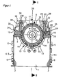
- the Fig. 1 and 2 show the invention at a glance.
- the device shown has a substantially symmetrical structure based on a machine base frame with two plane-parallel transverse walls 1, which are connected in their lower corners of lower longitudinal beams 2 and in their upper corners of upper longitudinal members 3 together.
- the longitudinal walls 4 are formed over their entire surface of doors 5, which are pivotable about the hinges 6 for opening and closing the housing and thus ensure accessibility to the interior of the device.
- a bracket 7 is welded in each case for receiving a shaft bearing 8.
- the shaft bearing 8 carry a rotor 9, which is essentially formed by a rotor drum 11, in the front side in each case a stub shaft 10 rotatably engages.
- the two stub shafts 10 extend with their free ends through openings in the transverse walls 1 to the shaft bearings 8.
- the rotor 9 is fitted over its circumference with a plurality of tool units 12, which are spaced apart both in the circumferential direction and in the axial direction.
- Each tool unit 12 is replaceably mounted in a receptacle on the lateral surface of the rotor drum 11, which is under FIG. 5 is described in more detail.
- the rotor 9 can be operated in both directions of rotation.
- the lower peripheral portion of the rotor 9 is surrounded by a screen web, which is formed in the present example of four sieve elements 13.
- Each sieve element 13 consists essentially of a portafilter 14, on which a perforated screen 15 is clamped.
- two sieve elements 13 extend in mirror image over approximately a quarter of the rotor circumference ( FIG. 1 ); longitudinally two sieve elements 13 follow each other axially ( FIG. 2 ).
- axle bearings 17 are arranged on the inside of the transverse wall 1 and on both sides of an intermediate wall, in which the filter holder 14 are rotatably mounted.
- the sieve elements 13 can each be pivoted downwards. With the doors 5 open access to the perforated screens 15 and the rotor 9 is thus ensured.
- the upper longitudinal beams 3 each serve for the stationary mounting of an axially parallel stator device, with a stator tool carrier 19, which extends over the entire axial distance of the two transverse walls 1 away.
- the top of Statorwerkmaschinechtiss 19 is inclined to the rotor 9 and forms a support surface for plate-shaped stator 21, which are clamped by means of clamping plates 22 and clamping screws 23 against the Statorwerkmaschineitati 19.
- In the area of the outer longitudinal sides of the Statortechnikmaschinemaschine 1976 19 also see adjusting screws 24, with which a radial adjustment or readjustment of the stator 21 can be made to ensure the intended working gap between the tool units 12 of the rotor 9 and the stator.
- the rotor 9 and the stator device thus have a substantially symmetrical structure to the vertical plane through the axis of rotation.
- the supply of the feed material via a vertical feed chute 25, connect the longitudinal walls 26 in the vertical direction directly to the stator.
- the longitudinal walls 26 In the connection region to the stator devices, the longitudinal walls 26 each have an opening 27 which extends from the one transverse wall 1 to the opposite.
- the transverse walls of the feed chute 25 are reinforced with respect to the transverse walls 1 of the machine base frame and continue upwards beyond the rotor 9.
- Each opening 27 is closed by a flap 28, which is mounted analogously to the screen elements 13 pivotally mounted in the transverse walls 1.
- the pivot axes 29 of the flaps 28 lie in the region of the upper longitudinal edge of a flap 28, where axial bearing journals are provided for this purpose.
- To protect the terminal gap between a movable flap 28 and the upwardly continuing rigid portion of the Zutechnologyschachts 25 have the longitudinal walls 26 on its inner side along its lower edge in each case a strip-shaped skirt 30 which overlaps the upper longitudinal edge of the flap 28.
- a deflector plate 33 extends over its entire length and extends inclined towards its free edge in order to prevent accumulation of material in the swivel range of the flaps 28.
- the drive of the flaps 28 is analogous to the drive of the sieve elements 13 by means of cylinder piston units, not shown, whose cylinders are fixedly connected to the outside of the transverse walls of the feed chute 25, while the movable actuating piston each seated on a rotationally fixed on the journal of the flaps 28 Lever is articulated.
- the cylinder piston units By extending the cylinder piston units, the pivotal movement of the flaps 28 is generated.
- the Fig. 3 to 6 show the closer construction of a tool unit 12 and its attachment to the rotor 9.
- the tool unit 12 comprises a tool carrier 34 which is composed of a first sub-carrier 31 and a second sub-carrier 32, which have an identical structure.
- Each sub-carrier 31, 32 has approximately cuboid shape with a flat bottom 35 and plan end faces 36, wherein the edges are chamfered.
- the front side 37 of the tool sub-carriers 31, 32 essentially serves to receive any number of tools, which in the present example are formed by four side-by-side, plate-shaped cutting crowns 38 with a square outline.
- Each cutting crown 38 is aligned so that its one diagonal runs parallel to the longitudinal direction of the sub-beams 31, 32 and the other diagonal perpendicular to it.
- the upper sides of the sub-carriers 31, 32 follow the course of the effective edge 41 while maintaining a small edge distance, resulting in a small radial projection of the cutting crowns 38 over the sub-carriers 31, 32.
- the cutting crowns 38 are arranged in receptacles 39 on the front side 37 of the carriers 31, 32.
- the pictures 39 are each formed by a to the rear side 42 of the sub-carrier 31, 32 out offset bearing surface 40.
- strip-shaped support surfaces 43 which receive two adjacent sides of a cutting bit 38 form fit.
- the transition between the two support surfaces 43 is formed by a fillet 44.
- the bearing surfaces 40 each have a central through-bore 46 for the passage of a fastening screw 47 ( Fig. 5 ). To illustrate this fact is in FIG. 3 the left in the drawing plane cutting crown 38 is not shown.
- the back 42 of the sub-carrier 31, 32 is substantially planar. In the exit region of the through holes 46, however, local recesses 48 are provided, in which the ends of the fastening screws 47 are anchored by means of nuts screwed 49. Below the recesses 48 at about half the distance to the bottom 35 of the sub-carrier 31, 32 can be seen a parallel to the bottom 35 extending keyway 50, which is intended for the positive reception of a Passefeder 51.
- FIGS. 3 and 5 It can be seen that in order to obtain a tool unit 12 according to the invention and its preparation for installation in a rotor 9, two sub-carriers 31, 32 are placed congruently against one another with their rear sides 42. In the common contact plane 52 while the key 51 ensures the centering of the first sub-carrier 31 relative to the second sub-carrier 32.
- Such a prepared tool unit 12 is inserted into a receptacle on the rotor 9, where the fixation solely by clamping with the aid of a radially clamped clamping wedge 53rd takes place, which exerts a relative to the axis of rotation tangentially directed clamping force on the tool unit 12.
- an inclined side surface of the clamping wedge 53 cooperates with a likewise inclined wall surface of a tool holder ( Fig. 5 ).
- Fig. 6 shows the contact region of two adjacently arranged on a sub-carrier 31, 32, rectangular or square processing tools in the form of cutting crowns 38.
- the opposing tips have flats 54 in the end, which allow a full-surface juxtaposition of the processing tools in the region of the flats 54.
- This has the advantage that even after occurrence of the first signs of wear, the effective edge 41 formed by the entirety of the processing tools is maintained throughout.
- advantageous size of the flats 54 results when the diagonal spacing of the flats corresponds approximately to 0.9 times to 0.95 times the distance between the two other peaks without flattening.
- the invention is not limited to the present embodiment, but rather also includes embodiments in which a tool extends integrally over an entire sub-carrier. Likewise, embodiments are possible in which the effective edge formed by the tools has a deviating from the zigzag course, for example, runs straight or undulating.
Abstract
Description
Die Erfindung betrifft eine Werkzeugeinheit für eine Zerkleinerungsvorrichtung gemäß dem Oberbegriff des Patentanspruchs 1, ein Schneid- oder Stanzwerkzeug gemäß dem Oberbegriff des Patentanspruchs 11 sowie eine Vorrichtung gemäß Patentanspruch 13.The invention relates to a tool unit for a comminution device according to the preamble of patent claim 1, a cutting or punching tool according to the preamble of
Die Erfindung ist dem Gebiet der mechanischen Verfahrenstechnik und dort insbesondere der Zerkleinerung fester schüttfähiger Stoffe zuzuordnen. Ein bevorzugtes Einsatzgebiet liegt unter anderem in der Bearbeitung von Müll oder der Wiedergewinnung von Wertstoffen im Zuge des Recyclings. Beispielhaft seien Kunststoffe, Gummi, Holz, Altholz, Papier, Kartonagen, Textilien, Sammlungen aus dem Dualen System und dergleichen als mögliches Aufgabegut genannt. Mit der Zerkleinerung derartiger Materialien ist ein nicht unerheblicher Verschleiß der Zerkleinerungswerkzeuge verbunden, die in der Folge regelmäßig gegen unverbrauchte ausgetauscht werden müssen. Die damit einhergehenden Maschinenstillstandszeiten bestimmen maßgeblich die Wirtschaftlichkeit des Zerkleinerungsbetriebs.The invention is to be assigned to the field of mechanical process engineering, and in particular to the comminution of solid, pourable substances. A preferred field of application is inter alia in the processing of waste or the recovery of recyclables in the course of recycling. Examples include plastics, rubber, wood, waste wood, paper, cardboard, textiles, collections from the dual system and the like called as possible feedstock. With the crushing of such materials, a considerable wear of the crushing tools is connected, which must be replaced regularly as a result against unused. The associated machine downtimes decisively determine the economic efficiency of the comminution operation.
Aus der
Vor diesem Hintergrund besteht die Aufgabe der Erfindung darin, die wechselbedingten Stillstandszeiten einer Zerkleinerungsvorrichtung zu mindern und auf diese Weise die Wirtschaftlichkeit des Zerkleinerungsprozesses zu steigern.Against this background, the object of the invention is to reduce the change-related downtime of a crushing device and to increase in this way the efficiency of the crushing process.
Diese Aufgabe wird durch eine Werkzeugeinheit mit den Merkmalen des Patentanspruchs 1, einem Schneid- oder Stanzwerkzeug mit den Merkmalen des Patentanspruchs 11 und einer Vorrichtung mit den Merkmalen des Patentanspruchs 13 gelöst.This object is achieved by a tool unit having the features of patent claim 1, a cutting or punching tool having the features of
Vorteilhafte Ausführungsformen ergeben sich aus den Unteransprüchen.Advantageous embodiments will be apparent from the dependent claims.
Die Erfindung basiert auf dem Grundgedanken, mehrere Bearbeitungswerkzeuge wie zum Beispiel Messer auf einem lösbar mit dem Rotor verbundenen Werkzeugträger anzuordnen, wobei die sich dabei ergebende Werkzeugeinheit beim Tausch der Werkzeuge als Ganzes gehandhabt werden kann. Mit dem Tausch einer Werkzeugeinheit werden also eine Vielzahl Werkzeuge auf einmal gewechselt. Die Bestückung der Werkzeugträger kann dabei außerhalb der Vorrichtung bei laufendem Betrieb erfolgen, so dass sich der Zeitaufwand für den Werkzeugwechsel auf den Tausch vergleichsweise weniger Werkzeugeinheiten konzentrieren lässt. Auf diese Weise werden wechselbedingte Stillstandszeiten beträchtlich reduziert.The invention is based on the idea of arranging a plurality of machining tools, such as knives, on a tool carrier that is detachably connected to the rotor, wherein the resulting tool unit can be handled as a whole when exchanging the tools. With the replacement of a tool unit so a variety of tools are changed at once. The equipment of the tool carrier can be done outside the device during operation, so that the time required for the tool change concentrate on the exchange comparatively fewer tool units. In this way, change-related downtimes are considerably reduced.
Gemäß der Erfindung sind dabei die einzelnen Messerträger zweigeteilt, wobei jeder Teilträger mit seiner Vorderseite die Werkzeuge aufnimmt und mit seiner Rückseite an der Rückseite des anderen Teilträgers anliegt. Da die Teilträger vorzugsweise einen identischen Aufbau aufweisen, können zwei beliebige mit Werkzeugen bestückte Teilträger zu einer Werkzeugeinheit zusammengesetzt werden. Die Anzahl und damit die Vorhaltung unterschiedlicher Bauteile ist folglich sehr gering.According to the invention, the individual knife carriers are divided into two, each sub-carrier with its front side receives the tools and rests with its back on the back of the other sub-carrier. Since the sub-carriers preferably have an identical structure, any two sub-carriers equipped with tools can be assembled to form a tool unit. The number and thus the provision of different components is therefore very low.
Die sich beim Zusammenbau der Werkzeugeinheiten einstellende Symmetrie eröffnet mehrere Möglichkeiten, einen Werkzeugwechsel äußerst effektiv durchführen zu können. Aufgrund der zur Kontaktebene der beiden Teilträger symmetrischen Anordnung der Werkzeuge kann eine Werkzeugeinheit nach ihrem Lösen aus der Aufnahme und nach Drehen um 180° um eine radial gerichtete Achse wieder am Rotor befestigt werden. Bei gleichbleibendem Drehsinn des Rotors kommen auf diese Weise die bislang im Bewegungsschatten gelegenen Werkzeuge auf die in Rotationsrichtung weisende Vorderseite der Werkzeugeinheit. Der gleiche Effekt lässt sich erzielen, indem anstelle des Drehens der Werkzeugeinheiten die Rotationsrichtung des Rotors gewechselt wird. Auf diese Weise erfolgt eine Umstellung der Vorrichtung auf unverbrauchte Werkzeuge, ohne Arbeiten am Rotor ausführen zu müssen. Die Standzeit des Rotors lässt sich auf diese Weise verdoppeln, das heißt die Stillstandszeiten halbieren sich.The symmetry that builds up when assembling the tool units opens up several possibilities for performing a tool change extremely effectively. Due to the symmetrical to the contact plane of the two sub-carrier arrangement of the tools, a tool unit after its release from the recording and after rotation by 180 ° about a radially directed axis can be fixed to the rotor again. At constant rotation of the rotor come in this way so far in the Moving shadow tools on the facing in the direction of rotation front of the tool unit. The same effect can be achieved by changing the direction of rotation of the rotor instead of turning the tool units. In this way, a conversion of the device to unused tools, without having to do any work on the rotor. The service life of the rotor can be doubled in this way, that is, the downtime is halved.
Erfolgt die Befestigung der Werkzeuge an den Teilträgern mit Hilfe von Befestigungsschrauben, so können vorteilhafterweise die den Schraubenköpfen gegenüberliegenden Enden der Befestigungsschrauben in Vertiefungen an der Rückseite der Teilträger angeordnet sein. Damit wird einerseits ein vollflächiges behinderungsfreies Anliegen der beiden Teilträger aneinander gewährleistet; andererseits wird sicher gestellt, dass die zum Lösen der Werkzeuge maßgeblichen Enden der Befestigungsschrauben vor mechanischer Krafteinwirkung während des Zerkleinerungsbetriebs geschützt sind. Auf diese Weise bleiben die Befestigungsmittel im Verankerungsbereich unversehrt und lassen sich somit problemlos lösen.If the tools are fastened to the sub-carriers with the aid of fastening screws, the ends of the fastening screws opposite the screw heads can advantageously be arranged in depressions on the rear side of the sub-carriers. Thus, on the one hand a full-surface disability-free concerns of the two sub-carriers is guaranteed to each other; On the other hand, it is ensured that the decisive for releasing the tools relevant ends of the fastening screws are protected against mechanical force during the crushing operation. In this way, the fasteners in the anchoring area remain intact and can thus be solved easily.
Um die beiden Teilträger passgenau zusammenfügen und in dieser Lage in den Rotor einbauen zu können, sind in der gemeinsamen Kontaktebene der Teilträger vorteilhafterweise Formschlussmittel angeordnet. Neben der damit erreichten Zentrierung der beiden Teilträger, bewirken die Formschlussmittel wie zum Beispiel Passfedern oder Passstifte durch den Reibschluss zur Passfedernut oder Passbohrung einen gewissen Zusammenhalt der beiden Teilträger, was deren Handhabung beim Werkzeugwechsel erleichtert ohne jedoch das Zerlegen einer Werkzeugeinheit nennenswert zu behindern.In order to assemble the two sub-carrier with a precise fit and to be able to install in this position in the rotor, positive-locking means are advantageously arranged in the common contact plane of the sub-carrier. In addition to the achieved centering of the two sub-carrier, cause the interlocking means such as feathers or dowel pins by the frictional engagement with the keyway or fitting bore a certain cohesion of the two sub-carrier, which facilitates their handling when changing tools without hampering the disassembly of a tool unit appreciably.
Bei einer vorteilhaften Ausführungsform der Erfindung ist vorgesehen, dass zwei zueinander benachbarte Lagerflächen eines Teilträgers mit einem Versatz senkrecht zur Lagerfläche angeordnet sind. Diesen Versatz weisen folglich auch die Werkzeuge auf, so dass im Zuge der Rotation des Rotors nicht alle Werkzeuge einer Werkzeugeinheit gleichzeitig in Eingriff mit dem Aufgabegut kommen, sondern sukzessive. Der vom Aufgabegut aufgebrachte Widerstand wird auf diese Weise vergleichmäßigt und Spitzenbeanspruchungen reduziert. Ein vergleichbarer Effekt lässt sich erzielen, wenn die Lagerflächen für die Bearbeitungswerkzeuge im Winkel zur Längserstreckung der Teilträger verlaufen.In an advantageous embodiment of the invention it is provided that two mutually adjacent bearing surfaces of a sub-carrier are arranged with an offset perpendicular to the bearing surface. Consequently, the tools also have this offset, so that not all tools of a tool unit simultaneously engage with the feed material during the rotation of the rotor, but successively. The resistance applied by the feedstock is thus evened out and peak stresses are reduced. A comparable effect can be achieved if the bearing surfaces for the processing tools are at an angle to the longitudinal extent of the sub-carriers.
Von der Erfindung bevorzugtes Verbindungsmittel sind Schrauben, wobei zum Schutz des Schraubenkopfes dieser in einer Senkbohrung im Werkzeug zu liegen kommt. Vorzugsweise ist die konische Laibungsfläche der Senkbohrung zusätzlich konvex ausgebildet, so dass sich eine ringförmige Anlage des Schraubenkopfes in der Senkbohrung ergibt. Auf diese Weise können Winkeltoleranzen der Befestigungsschraube ausgeglichen werden, ohne dass dabei Zwängungen entstehen.Preferred by the invention connecting means are screws, which comes to lie in a counterbore in the tool to protect the screw head. Preferably, the conical reveal surface of the counterbore is additionally convex, so that there is an annular contact of the screw head in the counterbore. In this way, angular tolerances of the fastening screw can be compensated without causing constraints.
In vorteilhafter Weiterbildung der Erfindung sind zur Befestigung der Werkzeugeinheiten am Rotor Aufnahmen bildende Vertiefungen im Rotormantel angeordnet. Eine Werkzeugeinheit wird radial in eine Aufnahme gesteckt und dort mittels eines Spannkeils tangential gegen eine Wand der Aufnahme gespannt. Dabei wird der Spannkeil mittels einer Spannschraube radial gegen den Boden der Aufnahme gespannt. Bei einer solchen Befestigungsart ist die Spannschraube also radial zugänglich und kann daher ohne Einschränkungen der Bewegungsfreiheit schnell und einfach gelöst werden.In an advantageous embodiment of the invention recordings forming depressions are arranged in the rotor shell for mounting the tool units on the rotor. A tool unit is inserted radially into a receptacle and clamped there by means of a clamping wedge tangentially against a wall of the receptacle. The clamping wedge is clamped by means of a clamping screw radially against the bottom of the recording. With such a fastening, the clamping screw is thus radially accessible and can therefore be solved quickly and easily without restrictions on the freedom of movement.
Die Erfindung wird nachstehend anhand eines in den Zeichnungen dargestellten Ausführungsbeispiels näher erläutert, aus dem sich weitere Merkmale und Vorteile der Erfindung ergeben.The invention will be explained in more detail with reference to an embodiment shown in the drawings, from which further features and advantages of the invention will be apparent.
Es zeigt
- Fig. 1
- einen Querschnitt durch eine erfindungsgemäße Vorrichtung entlang der in
Fig. 2 dargestellten Linie I - I, - Fig. 2
- einen Längsschnitt durch die in
Fig. 1 dargestellte Vorrichtung entlang der dortigen Linie II - II, - Fig. 3
- eine Schrägansicht auf eine erfindungsgemäße Werkzeugeinheit,
- Fig. 4
- eine Seitenansicht der in
Figur 3 - Fig. 5
- einen Querschnitt durch die in
Figur 4 dargestellten Werkzeugeinheit entlang der dortigem Linie V - V, und - Fig. 6
- den in
Figur 4 mit VI gekennzeichneten Bereich in größerem Maßstab.
- Fig. 1
- a cross section through a device according to the invention along the in
Fig. 2 illustrated line I - I, - Fig. 2
- a longitudinal section through the in
Fig. 1 shown device along the local line II - II, - Fig. 3
- an oblique view of a tool unit according to the invention,
- Fig. 4
- a side view of in
FIG. 3 shown tool unit, - Fig. 5
- a cross section through the in
FIG. 4 shown tool unit along the local line V - V, and - Fig. 6
- the in
FIG. 4 Area marked VI on a larger scale.
Die
An der Außenseite der beiden Querwände 1 ist jeweils zur Aufnahme eines Wellenlagers 8 eine Konsole 7 angeschweißt. Die Wellenlager 8 tragen einen Rotor 9, der im Wesentlichen von einer Rotortrommel 11 gebildet ist, in die stirnseitig jeweils ein Wellenstummel 10 drehfest eingreift. Die beiden Wellenstummel 10 erstrecken sich mit ihren freien Enden durch Öffnungen in den Querwänden 1 bis zu den Wellenlagern 8. Der Rotor 9 ist über seinen Umfang mit einer Vielzahl von Werkzeugeinheiten 12 bestückt, die sowohl in Umfangsrichtung als auch in axialer Richtung zueinander beabstandet sind. Jede Werkzeugeinheit 12 ist dabei in einer Aufnahme an der Mantelfläche der Rotortrommel 11 auswechselbar befestigt, was unter
Der untere Umfangsabschnitt des Rotors 9 ist von einer Siebbahn umgeben, die im vorliegenden Beispiel von vier Siebelementen 13 gebildet ist. Jedes Siebelement 13 besteht im Wesentlichen aus einem Siebträger 14, auf dem ein Lochsieb 15 aufgespannt ist. Im Querschnitt erstrecken sich zwei Siebelemente 13 spiegelbildlich über annähernd ein Viertel des Rotorumfangs (
Zur schwenkbaren Lagerung der Siebelemente 13 sind an der Innenseite der Querwand 1 bzw. beidseitig an einer Zwischenwand 16 Achslager 17 angeordnet, in denen die Siebträger 14 drehbar gelagert sind. Mit Hilfe der Zylinderkolbeneinheiten 18 an der Außenseite der Querwände 1, deren bewegliche Kolben über Stellhebel auf die Siebträger 14 wirken, lassen sich die Siebelemente 13 jeweils nach unten schwenken. Bei geöffneten Türen 5 ist somit der Zugang zu den Lochsieben 15 und dem Rotor 9 gewährleistet.For pivotal mounting of the
Die oberen Längsholme 3 dienen jeweils der ortsfesten Lagerung einer achsparallelen Statoreinrichtung, mit einem Statorwerkzeugträger 19, der sich über den gesamten axialen Abstand der beiden Querwände 1 hinweg erstreckt. Die Oberseite des Statorwerkzeugträgers 19 ist dabei zum Rotor 9 hin geneigt und bildet eine Auflagerfläche für plattenförmige Statorwerkzeuge 21, die mit Hilfe von Klemmplatten 22 und Spannschrauben 23 gegen den Statorwerkzeugträger 19 gespannt sind. Im Bereich der äußeren Längsseiten der Statorwerkzeugträger 19 sieht man zudem Justierschrauben 24, mit denen eine radiale Einstellung bzw. Nachstellung der Statorwerkzeuge 21 vorgenommen werden kann, um den bestimmungsgemäßen Arbeitsspalt zwischen den Werkzeugeinheiten 12 des Rotors 9 und der Statoreinrichtung zu gewährleisten. Der Rotor 9 und die Statoreinrichtung weisen damit einen im Wesentlichen symmetrischen Aufbau zur vertikalen Ebene durch die Rotationsachse auf.The upper
Die Zufuhr des Aufgabeguts erfolgt über einen vertikalen Zuführschacht 25, dessen Längswände 26 in vertikaler Richtung unmittelbar an die Statoreinrichtung anschließen. Im Anschlussbereich an die Statoreinrichtungen weisen die Längswände 26 jeweils eine Öffnung 27 auf, die sich von der einen Querwand 1 zur gegenüberliegenden erstreckt. Die Querwände des Zuführschachts 25 sind gegenüber den Querwänden 1 des Maschinengrundrahmens verstärkt und setzen sich nach oben bis über den Rotor 9 hinaus fort.The supply of the feed material via a
Jede Öffnung 27 ist von einer Klappe 28 verschlossen, die analog den Siebelementen 13 schwenkbar in den Querwänden 1 gelagert ist. Die Schwenkachsen 29 der Klappen 28 liegen dabei im Bereich des oberen Längsrandes einer Klappe 28, wo zu diesem Zweck axiale Lagerzapfen vorgesehen sind. Zum Schutz des Anschlussspalts zwischen einer beweglichen Klappe 28 und dem sich nach oben fortsetzenden starren Bereich des Zuführschachts 25 besitzen die Längswände 26 an ihrer Innenseite entlang ihres unteren Randes jeweils eine leistenförmige Schürze 30, die den oberen Längsrand der Klappe 28 überlappt. An der dem Rotor 9 abgewandten Rückseite der Klappen 28 erstreckt sich über deren gesamte Länge ein Abweisblech 33, das zu seinem freien Rand hin geneigt verläuft, um Materialansammlungen im Schwenkbereich der Klappen 28 zu verhindern.Each
Der Antrieb der Klappen 28 erfolgt analog dem Antrieb der Siebelemente 13 mit Hilfe von nicht dargestellten Zylinderkolbeneinheiten, deren Zylinder an der Außenseite der Querwände des Zuführschachts 25 fest mit diesen verbunden sind, während deren bewegliche Stellkolben jeweils an einen drehfest auf dem Lagerzapfen der Klappen 28 sitzenden Hebel angelenkt ist. Durch Ausfahren der Zylinderkolbeneinheiten wird die Schwenkbewegung der Klappen 28 erzeugt.The drive of the
Die
Die Oberseiten der Teilträger 31, 32 folgen unter Einhaltung eines geringen Randabstandes dem Verlauf der wirksamen Kante 41, wodurch sich ein geringer radialer Überstand der Schneidkronen 38 über die Teilträger 31, 32 ergibt.The upper sides of the
Zu ihrer sicheren Befestigung an den Teilträgern 31, 32 sind die Schneidkronen 38 in Aufnahmen 39 an der Vorderseite 37 der Träger 31, 32 angeordnet. Die Aufnahmen 39 werden jeweils von einer zur Rückseite 42 der Teilträger 31, 32 hin versetzten Lagerfläche 40 gebildet. Durch den senkrecht zur Lagerfläche 40 verlaufenden Versatz entstehen streifenförmige Stützflächen 43, die zwei benachbarte Seiten einer Schneidkrone 38 formschlüssig aufnehmen. Der Übergang zwischen den beiden Stützflächen 43 wird dabei von einer Ausrundung 44 gebildet. Die Lagerflächen 40 weisen jeweils eine zentrale Durchgangsbohrung 46 zur Durchführung einer Befestigungsschraube 47 auf (
Die Rückseite 42 der Teilträger 31, 32 ist im Wesentlichen plan ausgebildet. Im Austrittsbereich der Durchgangsbohrungen 46 sind jedoch lokale Vertiefungen 48 vorgesehen, in denen die Enden der Befestigungsschrauben 47 mit Hilfe aufgeschraubter Muttern 49 verankert sind. Unterhalb der Vertiefungen 48 etwa im halben Abstand zur Unterseite 35 der Teilträger 31, 32 sieht man eine parallel zur Unterseite 35 verlaufende Passfedernut 50, die zur formschlüssigen Aufnahme einer Passefeder 51 bestimmt ist.The back 42 of the
Wie vor allem aus den
Die Erfindung ist nicht auf das vorliegende Ausführungsbeispiel beschränkt, sondern umfasst vielmehr auch Ausführungsformen, bei denen sich ein Werkzeug einstückig über einen gesamten Teilträger erstreckt. Ebenso sind Ausführungsformen möglich, bei denen die von den Werkzeugen gebildete wirksame Kante einen von der Zickzackform abweichenden Verlauf aufweist, beispielsweise gerade oder wellenförmig verläuft.The invention is not limited to the present embodiment, but rather also includes embodiments in which a tool extends integrally over an entire sub-carrier. Likewise, embodiments are possible in which the effective edge formed by the tools has a deviating from the zigzag course, for example, runs straight or undulating.
Claims (13)
Applications Claiming Priority (1)
| Application Number | Priority Date | Filing Date | Title |
|---|---|---|---|
| DE102011119589A DE102011119589A1 (en) | 2011-11-29 | 2011-11-29 | Tool unit and cutting or punching tool for a shredding device and device equipped therewith |
Publications (3)
| Publication Number | Publication Date |
|---|---|
| EP2599553A2 true EP2599553A2 (en) | 2013-06-05 |
| EP2599553A3 EP2599553A3 (en) | 2013-09-25 |
| EP2599553B1 EP2599553B1 (en) | 2018-09-26 |
Family
ID=47290542
Family Applications (1)
| Application Number | Title | Priority Date | Filing Date |
|---|---|---|---|
| EP12007946.2A Not-in-force EP2599553B1 (en) | 2011-11-29 | 2012-11-26 | Tool unit and cutting or stamping tool for a reduction tool, and device equipped with the same |
Country Status (3)
| Country | Link |
|---|---|
| US (1) | US8967515B2 (en) |
| EP (1) | EP2599553B1 (en) |
| DE (1) | DE102011119589A1 (en) |
Cited By (2)
| Publication number | Priority date | Publication date | Assignee | Title |
|---|---|---|---|---|
| EP2848311A1 (en) * | 2013-09-11 | 2015-03-18 | Manuel Lindner | Blade for a shredding apparatus |
| CN114887732A (en) * | 2022-05-20 | 2022-08-12 | 重庆电子工程职业学院 | Automatic colliery rubbing crusher of tool changing |
Families Citing this family (5)
| Publication number | Priority date | Publication date | Assignee | Title |
|---|---|---|---|---|
| US10864523B2 (en) * | 2014-05-20 | 2020-12-15 | Eco Green Equipment, Llc | Shredder blade assembly |
| US20170252749A1 (en) * | 2016-03-03 | 2017-09-07 | Daniel T. Miller | Processing blade |
| US10128238B2 (en) | 2016-08-09 | 2018-11-13 | International Business Machines Corporation | Integrated circuit having oxidized gate cut region and method to fabricate same |
| US10662950B2 (en) | 2016-10-31 | 2020-05-26 | Roper Pump Company | Progressing cavity device with cutter disks |
| US10967380B2 (en) * | 2017-03-31 | 2021-04-06 | Stanley Black & Decker, Inc. | Heavy duty material processor |
Citations (1)
| Publication number | Priority date | Publication date | Assignee | Title |
|---|---|---|---|---|
| DE19537581A1 (en) | 1995-10-09 | 1997-04-10 | Vecoplan Maschf Gmbh | Cutter arrangement for rotor of fragmenting unit |
Family Cites Families (13)
| Publication number | Priority date | Publication date | Assignee | Title |
|---|---|---|---|---|
| US3314617A (en) * | 1964-01-29 | 1967-04-18 | Noble & Wood Machine Co | Pulper defibering means |
| US3857520A (en) * | 1972-10-27 | 1974-12-31 | Unice Machine Co | Oscillating anvil disintegrator |
| US4854508A (en) * | 1988-10-06 | 1989-08-08 | Columbus Mckinnon Corporation | Tire shredding machine |
| US5318231A (en) * | 1992-10-20 | 1994-06-07 | Norman J. Emanuel | Rotary shredding cutters |
| US5375775A (en) * | 1993-08-20 | 1994-12-27 | Keller; Mark E. | Tire recycling apparatus and method |
| FI105657B (en) * | 1998-10-14 | 2000-09-29 | Bmh Wood Technology Oy | Crusher rotor and method for machining crusher rotor casing surface |
| FI105656B (en) * | 1998-10-14 | 2000-09-29 | Bmh Wood Technology Oy | Crusher rotor gear |
| US6343755B1 (en) * | 2000-03-31 | 2002-02-05 | Randel L. Barclay | Tire shredding machinery |
| FR2809333B1 (en) * | 2000-05-25 | 2002-08-16 | Precimeca | IMPROVED WASTE GRINDER, COMPONENTS AND MAINTENANCE METHOD |
| DE10146773A1 (en) * | 2001-09-22 | 2003-04-17 | Deere & Co | Fastening arrangement for fastening beaters to a rotor of a straw chopper |
| EP1362639A1 (en) * | 2002-05-08 | 2003-11-19 | UNTERWURZACHER PATENTVERWERTUNGSGESELLSCHAFT mbH | Grinding apparatus for shredding of material |
| FR2908671B1 (en) * | 2006-11-17 | 2009-02-13 | Precimeca Sa | DEVICE FOR MILLING WASTE |
| SE530386C2 (en) * | 2007-01-12 | 2008-05-20 | Iggesund Tools Ab | Chipper knife for producing paper pulp, has two edge forming surfaces formed with thickened cutting edge portion in area next to cutting edge, where thickened cutting edge portion has shoulder edge towards rest of surface |
-
2011
- 2011-11-29 DE DE102011119589A patent/DE102011119589A1/en not_active Ceased
-
2012
- 2012-11-26 EP EP12007946.2A patent/EP2599553B1/en not_active Not-in-force
- 2012-11-29 US US13/688,874 patent/US8967515B2/en not_active Expired - Fee Related
Patent Citations (1)
| Publication number | Priority date | Publication date | Assignee | Title |
|---|---|---|---|---|
| DE19537581A1 (en) | 1995-10-09 | 1997-04-10 | Vecoplan Maschf Gmbh | Cutter arrangement for rotor of fragmenting unit |
Cited By (2)
| Publication number | Priority date | Publication date | Assignee | Title |
|---|---|---|---|---|
| EP2848311A1 (en) * | 2013-09-11 | 2015-03-18 | Manuel Lindner | Blade for a shredding apparatus |
| CN114887732A (en) * | 2022-05-20 | 2022-08-12 | 重庆电子工程职业学院 | Automatic colliery rubbing crusher of tool changing |
Also Published As
| Publication number | Publication date |
|---|---|
| US20130134250A1 (en) | 2013-05-30 |
| EP2599553B1 (en) | 2018-09-26 |
| US8967515B2 (en) | 2015-03-03 |
| DE102011119589A1 (en) | 2013-05-29 |
| EP2599553A3 (en) | 2013-09-25 |
Similar Documents
| Publication | Publication Date | Title |
|---|---|---|
| EP2599553B1 (en) | Tool unit and cutting or stamping tool for a reduction tool, and device equipped with the same | |
| EP2218507B1 (en) | Device for grinding dispensed products with stripping elements | |
| EP2012927B1 (en) | Comminuting device | |
| EP1843891B1 (en) | Die table for rotary tablet presses and rotary tablet press | |
| EP2428274B1 (en) | Device for grinding dispensed products | |
| EP2679309B1 (en) | Crushing device comprising a crushing rotor with continuous cutting edge | |
| EP1731223B1 (en) | Comminutor | |
| EP1899072B1 (en) | Shredding device | |
| DE102009060523A1 (en) | Crushing device with counter knife device | |
| EP2082807B1 (en) | Reducing device with opposing rotors | |
| EP2374544B1 (en) | Device for grinding compostable material | |
| EP0203272A2 (en) | Crushing apparatus with a revolving rotor | |
| DE102007043687A1 (en) | Cutting tool for chipping machine especially for waste wood has support plate secured to chipping rotor via two screw fasteners straddling the median plane | |
| DE102009020712A1 (en) | Device for processing feed material with a rotor-stator system | |
| EP3315201B1 (en) | Chipper rotor for a shredding machine | |
| DE102007040046B4 (en) | Rotorshredder | |
| DE112011104021T5 (en) | Table unit for a material crusher | |
| EP1099481B1 (en) | Comminuting machine | |
| EP3356048B1 (en) | Rotor for a comminuting device | |
| DE102005050105B4 (en) | Cutting unit for a shredding machine and method for producing the cutting unit | |
| DE602004008495T2 (en) | Industrial shredder | |
| EP2549892B1 (en) | Blade box for disintegrating device for organic matter | |
| EP1428928B1 (en) | Apparatus for grinding material and grinding element for such an apparatus | |
| DE102019007191A1 (en) | Shredding device, comprising a shredding rotor with tools that can be changed quickly, as well as a shredding system | |
| DE202021003040U1 (en) | Device for arming a knife ring of a knife ring flaker |
Legal Events
| Date | Code | Title | Description |
|---|---|---|---|
| PUAI | Public reference made under article 153(3) epc to a published international application that has entered the european phase |
Free format text: ORIGINAL CODE: 0009012 |
|
| AK | Designated contracting states |
Kind code of ref document: A2 Designated state(s): AL AT BE BG CH CY CZ DE DK EE ES FI FR GB GR HR HU IE IS IT LI LT LU LV MC MK MT NL NO PL PT RO RS SE SI SK SM TR |
|
| AX | Request for extension of the european patent |
Extension state: BA ME |
|
| RIC1 | Information provided on ipc code assigned before grant |
Ipc: B02C 18/14 20060101AFI20130503BHEP Ipc: B02C 18/18 20060101ALI20130503BHEP |
|
| PUAL | Search report despatched |
Free format text: ORIGINAL CODE: 0009013 |
|
| AK | Designated contracting states |
Kind code of ref document: A3 Designated state(s): AL AT BE BG CH CY CZ DE DK EE ES FI FR GB GR HR HU IE IS IT LI LT LU LV MC MK MT NL NO PL PT RO RS SE SI SK SM TR |
|
| AX | Request for extension of the european patent |
Extension state: BA ME |
|
| RIC1 | Information provided on ipc code assigned before grant |
Ipc: B02C 18/18 20060101ALI20130821BHEP Ipc: B02C 18/14 20060101AFI20130821BHEP |
|
| 17P | Request for examination filed |
Effective date: 20140108 |
|
| RBV | Designated contracting states (corrected) |
Designated state(s): AL AT BE BG CH CY CZ DE DK EE ES FI FR GB GR HR HU IE IS IT LI LT LU LV MC MK MT NL NO PL PT RO RS SE SI SK SM TR |
|
| RAP1 | Party data changed (applicant data changed or rights of an application transferred) |
Owner name: PALLMANN MASCHINENFABRIK GMBH & CO. KG |
|
| GRAJ | Information related to disapproval of communication of intention to grant by the applicant or resumption of examination proceedings by the epo deleted |
Free format text: ORIGINAL CODE: EPIDOSDIGR1 |
|
| GRAP | Despatch of communication of intention to grant a patent |
Free format text: ORIGINAL CODE: EPIDOSNIGR1 |
|
| GRAP | Despatch of communication of intention to grant a patent |
Free format text: ORIGINAL CODE: EPIDOSNIGR1 |
|
| INTG | Intention to grant announced |
Effective date: 20180529 |
|
| GRAS | Grant fee paid |
Free format text: ORIGINAL CODE: EPIDOSNIGR3 |
|
| GRAA | (expected) grant |
Free format text: ORIGINAL CODE: 0009210 |
|
| AK | Designated contracting states |
Kind code of ref document: B1 Designated state(s): AL AT BE BG CH CY CZ DE DK EE ES FI FR GB GR HR HU IE IS IT LI LT LU LV MC MK MT NL NO PL PT RO RS SE SI SK SM TR |
|
| REG | Reference to a national code |
Ref country code: GB Ref legal event code: FG4D Free format text: NOT ENGLISH |
|
| REG | Reference to a national code |
Ref country code: CH Ref legal event code: EP |
|
| REG | Reference to a national code |
Ref country code: AT Ref legal event code: REF Ref document number: 1045362 Country of ref document: AT Kind code of ref document: T Effective date: 20181015 |
|
| REG | Reference to a national code |
Ref country code: IE Ref legal event code: FG4D Free format text: LANGUAGE OF EP DOCUMENT: GERMAN |
|
| REG | Reference to a national code |
Ref country code: DE Ref legal event code: R096 Ref document number: 502012013488 Country of ref document: DE |
|
| REG | Reference to a national code |
Ref country code: NL Ref legal event code: MP Effective date: 20180926 |
|
| PG25 | Lapsed in a contracting state [announced via postgrant information from national office to epo] |
Ref country code: GR Free format text: LAPSE BECAUSE OF FAILURE TO SUBMIT A TRANSLATION OF THE DESCRIPTION OR TO PAY THE FEE WITHIN THE PRESCRIBED TIME-LIMIT Effective date: 20181227 Ref country code: BG Free format text: LAPSE BECAUSE OF FAILURE TO SUBMIT A TRANSLATION OF THE DESCRIPTION OR TO PAY THE FEE WITHIN THE PRESCRIBED TIME-LIMIT Effective date: 20181226 Ref country code: RS Free format text: LAPSE BECAUSE OF FAILURE TO SUBMIT A TRANSLATION OF THE DESCRIPTION OR TO PAY THE FEE WITHIN THE PRESCRIBED TIME-LIMIT Effective date: 20180926 Ref country code: NO Free format text: LAPSE BECAUSE OF FAILURE TO SUBMIT A TRANSLATION OF THE DESCRIPTION OR TO PAY THE FEE WITHIN THE PRESCRIBED TIME-LIMIT Effective date: 20181226 Ref country code: LT Free format text: LAPSE BECAUSE OF FAILURE TO SUBMIT A TRANSLATION OF THE DESCRIPTION OR TO PAY THE FEE WITHIN THE PRESCRIBED TIME-LIMIT Effective date: 20180926 Ref country code: FI Free format text: LAPSE BECAUSE OF FAILURE TO SUBMIT A TRANSLATION OF THE DESCRIPTION OR TO PAY THE FEE WITHIN THE PRESCRIBED TIME-LIMIT Effective date: 20180926 Ref country code: SE Free format text: LAPSE BECAUSE OF FAILURE TO SUBMIT A TRANSLATION OF THE DESCRIPTION OR TO PAY THE FEE WITHIN THE PRESCRIBED TIME-LIMIT Effective date: 20180926 |
|
| REG | Reference to a national code |
Ref country code: LT Ref legal event code: MG4D |
|
| PG25 | Lapsed in a contracting state [announced via postgrant information from national office to epo] |
Ref country code: AL Free format text: LAPSE BECAUSE OF FAILURE TO SUBMIT A TRANSLATION OF THE DESCRIPTION OR TO PAY THE FEE WITHIN THE PRESCRIBED TIME-LIMIT Effective date: 20180926 Ref country code: LV Free format text: LAPSE BECAUSE OF FAILURE TO SUBMIT A TRANSLATION OF THE DESCRIPTION OR TO PAY THE FEE WITHIN THE PRESCRIBED TIME-LIMIT Effective date: 20180926 Ref country code: HR Free format text: LAPSE BECAUSE OF FAILURE TO SUBMIT A TRANSLATION OF THE DESCRIPTION OR TO PAY THE FEE WITHIN THE PRESCRIBED TIME-LIMIT Effective date: 20180926 |
|
| PG25 | Lapsed in a contracting state [announced via postgrant information from national office to epo] |
Ref country code: PL Free format text: LAPSE BECAUSE OF FAILURE TO SUBMIT A TRANSLATION OF THE DESCRIPTION OR TO PAY THE FEE WITHIN THE PRESCRIBED TIME-LIMIT Effective date: 20180926 Ref country code: EE Free format text: LAPSE BECAUSE OF FAILURE TO SUBMIT A TRANSLATION OF THE DESCRIPTION OR TO PAY THE FEE WITHIN THE PRESCRIBED TIME-LIMIT Effective date: 20180926 Ref country code: NL Free format text: LAPSE BECAUSE OF FAILURE TO SUBMIT A TRANSLATION OF THE DESCRIPTION OR TO PAY THE FEE WITHIN THE PRESCRIBED TIME-LIMIT Effective date: 20180926 Ref country code: IS Free format text: LAPSE BECAUSE OF FAILURE TO SUBMIT A TRANSLATION OF THE DESCRIPTION OR TO PAY THE FEE WITHIN THE PRESCRIBED TIME-LIMIT Effective date: 20190126 Ref country code: CZ Free format text: LAPSE BECAUSE OF FAILURE TO SUBMIT A TRANSLATION OF THE DESCRIPTION OR TO PAY THE FEE WITHIN THE PRESCRIBED TIME-LIMIT Effective date: 20180926 Ref country code: ES Free format text: LAPSE BECAUSE OF FAILURE TO SUBMIT A TRANSLATION OF THE DESCRIPTION OR TO PAY THE FEE WITHIN THE PRESCRIBED TIME-LIMIT Effective date: 20180926 Ref country code: IT Free format text: LAPSE BECAUSE OF FAILURE TO SUBMIT A TRANSLATION OF THE DESCRIPTION OR TO PAY THE FEE WITHIN THE PRESCRIBED TIME-LIMIT Effective date: 20180926 Ref country code: RO Free format text: LAPSE BECAUSE OF FAILURE TO SUBMIT A TRANSLATION OF THE DESCRIPTION OR TO PAY THE FEE WITHIN THE PRESCRIBED TIME-LIMIT Effective date: 20180926 |
|
| PG25 | Lapsed in a contracting state [announced via postgrant information from national office to epo] |
Ref country code: SK Free format text: LAPSE BECAUSE OF FAILURE TO SUBMIT A TRANSLATION OF THE DESCRIPTION OR TO PAY THE FEE WITHIN THE PRESCRIBED TIME-LIMIT Effective date: 20180926 Ref country code: SM Free format text: LAPSE BECAUSE OF FAILURE TO SUBMIT A TRANSLATION OF THE DESCRIPTION OR TO PAY THE FEE WITHIN THE PRESCRIBED TIME-LIMIT Effective date: 20180926 Ref country code: PT Free format text: LAPSE BECAUSE OF FAILURE TO SUBMIT A TRANSLATION OF THE DESCRIPTION OR TO PAY THE FEE WITHIN THE PRESCRIBED TIME-LIMIT Effective date: 20190126 |
|
| REG | Reference to a national code |
Ref country code: DE Ref legal event code: R119 Ref document number: 502012013488 Country of ref document: DE |
|
| REG | Reference to a national code |
Ref country code: CH Ref legal event code: PL |
|
| PG25 | Lapsed in a contracting state [announced via postgrant information from national office to epo] |
Ref country code: DK Free format text: LAPSE BECAUSE OF FAILURE TO SUBMIT A TRANSLATION OF THE DESCRIPTION OR TO PAY THE FEE WITHIN THE PRESCRIBED TIME-LIMIT Effective date: 20180926 Ref country code: LU Free format text: LAPSE BECAUSE OF NON-PAYMENT OF DUE FEES Effective date: 20181126 Ref country code: MC Free format text: LAPSE BECAUSE OF FAILURE TO SUBMIT A TRANSLATION OF THE DESCRIPTION OR TO PAY THE FEE WITHIN THE PRESCRIBED TIME-LIMIT Effective date: 20180926 |
|
| PLBE | No opposition filed within time limit |
Free format text: ORIGINAL CODE: 0009261 |
|
| STAA | Information on the status of an ep patent application or granted ep patent |
Free format text: STATUS: NO OPPOSITION FILED WITHIN TIME LIMIT |
|
| REG | Reference to a national code |
Ref country code: BE Ref legal event code: MM Effective date: 20181130 |
|
| REG | Reference to a national code |
Ref country code: IE Ref legal event code: MM4A |
|
| GBPC | Gb: european patent ceased through non-payment of renewal fee |
Effective date: 20181226 |
|
| PG25 | Lapsed in a contracting state [announced via postgrant information from national office to epo] |
Ref country code: CH Free format text: LAPSE BECAUSE OF NON-PAYMENT OF DUE FEES Effective date: 20181130 Ref country code: LI Free format text: LAPSE BECAUSE OF NON-PAYMENT OF DUE FEES Effective date: 20181130 |
|
| 26N | No opposition filed |
Effective date: 20190627 |
|
| PG25 | Lapsed in a contracting state [announced via postgrant information from national office to epo] |
Ref country code: SI Free format text: LAPSE BECAUSE OF FAILURE TO SUBMIT A TRANSLATION OF THE DESCRIPTION OR TO PAY THE FEE WITHIN THE PRESCRIBED TIME-LIMIT Effective date: 20180926 Ref country code: IE Free format text: LAPSE BECAUSE OF NON-PAYMENT OF DUE FEES Effective date: 20181126 Ref country code: DE Free format text: LAPSE BECAUSE OF NON-PAYMENT OF DUE FEES Effective date: 20190601 Ref country code: FR Free format text: LAPSE BECAUSE OF NON-PAYMENT OF DUE FEES Effective date: 20181126 |
|
| PG25 | Lapsed in a contracting state [announced via postgrant information from national office to epo] |
Ref country code: BE Free format text: LAPSE BECAUSE OF NON-PAYMENT OF DUE FEES Effective date: 20181130 |
|
| PG25 | Lapsed in a contracting state [announced via postgrant information from national office to epo] |
Ref country code: GB Free format text: LAPSE BECAUSE OF NON-PAYMENT OF DUE FEES Effective date: 20181226 |
|
| REG | Reference to a national code |
Ref country code: AT Ref legal event code: MM01 Ref document number: 1045362 Country of ref document: AT Kind code of ref document: T Effective date: 20181126 |
|
| PG25 | Lapsed in a contracting state [announced via postgrant information from national office to epo] |
Ref country code: MT Free format text: LAPSE BECAUSE OF FAILURE TO SUBMIT A TRANSLATION OF THE DESCRIPTION OR TO PAY THE FEE WITHIN THE PRESCRIBED TIME-LIMIT Effective date: 20180926 Ref country code: AT Free format text: LAPSE BECAUSE OF NON-PAYMENT OF DUE FEES Effective date: 20181126 |
|
| PG25 | Lapsed in a contracting state [announced via postgrant information from national office to epo] |
Ref country code: TR Free format text: LAPSE BECAUSE OF FAILURE TO SUBMIT A TRANSLATION OF THE DESCRIPTION OR TO PAY THE FEE WITHIN THE PRESCRIBED TIME-LIMIT Effective date: 20180926 |
|
| PG25 | Lapsed in a contracting state [announced via postgrant information from national office to epo] |
Ref country code: HU Free format text: LAPSE BECAUSE OF FAILURE TO SUBMIT A TRANSLATION OF THE DESCRIPTION OR TO PAY THE FEE WITHIN THE PRESCRIBED TIME-LIMIT; INVALID AB INITIO Effective date: 20121126 Ref country code: CY Free format text: LAPSE BECAUSE OF FAILURE TO SUBMIT A TRANSLATION OF THE DESCRIPTION OR TO PAY THE FEE WITHIN THE PRESCRIBED TIME-LIMIT Effective date: 20180926 Ref country code: MK Free format text: LAPSE BECAUSE OF NON-PAYMENT OF DUE FEES Effective date: 20180926 |