EP2598792B1 - Kraftfahrzeuglicht - Google Patents
Kraftfahrzeuglicht Download PDFInfo
- Publication number
- EP2598792B1 EP2598792B1 EP20110760548 EP11760548A EP2598792B1 EP 2598792 B1 EP2598792 B1 EP 2598792B1 EP 20110760548 EP20110760548 EP 20110760548 EP 11760548 A EP11760548 A EP 11760548A EP 2598792 B1 EP2598792 B1 EP 2598792B1
- Authority
- EP
- European Patent Office
- Prior art keywords
- shaped body
- cup
- light
- optical filter
- main cup
- Prior art date
- Legal status (The legal status is an assumption and is not a legal conclusion. Google has not performed a legal analysis and makes no representation as to the accuracy of the status listed.)
- Not-in-force
Links
- 230000003287 optical effect Effects 0.000 claims description 89
- 230000000694 effects Effects 0.000 claims description 20
- 230000006866 deterioration Effects 0.000 claims description 18
- 239000012780 transparent material Substances 0.000 claims description 11
- 239000000463 material Substances 0.000 claims description 8
- 230000005611 electricity Effects 0.000 claims description 4
- 229920003023 plastic Polymers 0.000 description 7
- 230000001795 light effect Effects 0.000 description 5
- 239000004033 plastic Substances 0.000 description 4
- 238000007373 indentation Methods 0.000 description 3
- 238000001746 injection moulding Methods 0.000 description 3
- 230000000737 periodic effect Effects 0.000 description 2
- 230000000295 complement effect Effects 0.000 description 1
- 239000012141 concentrate Substances 0.000 description 1
- 230000005489 elastic deformation Effects 0.000 description 1
- 238000003384 imaging method Methods 0.000 description 1
- 238000004519 manufacturing process Methods 0.000 description 1
- 239000007769 metal material Substances 0.000 description 1
- 230000007935 neutral effect Effects 0.000 description 1
- 229920003229 poly(methyl methacrylate) Polymers 0.000 description 1
- 239000004417 polycarbonate Substances 0.000 description 1
- 229920000515 polycarbonate Polymers 0.000 description 1
- 239000004926 polymethyl methacrylate Substances 0.000 description 1
- 238000001228 spectrum Methods 0.000 description 1
- 238000011144 upstream manufacturing Methods 0.000 description 1
Images

Classifications
-
- F—MECHANICAL ENGINEERING; LIGHTING; HEATING; WEAPONS; BLASTING
- F21—LIGHTING
- F21S—NON-PORTABLE LIGHTING DEVICES; SYSTEMS THEREOF; VEHICLE LIGHTING DEVICES SPECIALLY ADAPTED FOR VEHICLE EXTERIORS
- F21S43/00—Signalling devices specially adapted for vehicle exteriors, e.g. brake lamps, direction indicator lights or reversing lights
- F21S43/40—Signalling devices specially adapted for vehicle exteriors, e.g. brake lamps, direction indicator lights or reversing lights characterised by the combination of reflectors and refractors
-
- F—MECHANICAL ENGINEERING; LIGHTING; HEATING; WEAPONS; BLASTING
- F21—LIGHTING
- F21S—NON-PORTABLE LIGHTING DEVICES; SYSTEMS THEREOF; VEHICLE LIGHTING DEVICES SPECIALLY ADAPTED FOR VEHICLE EXTERIORS
- F21S43/00—Signalling devices specially adapted for vehicle exteriors, e.g. brake lamps, direction indicator lights or reversing lights
- F21S43/30—Signalling devices specially adapted for vehicle exteriors, e.g. brake lamps, direction indicator lights or reversing lights characterised by reflectors
- F21S43/31—Optical layout thereof
Definitions
- the present invention relates to an automotive light.
- the present invention relates to a rear light for cars, use to which the following description refers purely by way of example without implying any loss of generality.
- the car rear lights are usually made of a substantially basin-shaped, rigid rear casing which is structured so as to be permanently recessed into a compartment specifically made in the rear portion of the vehicle body; at least one cup-shaped body of substantially parabolic profile, which is located inside the rear casing with the concave side facing the mouth of the rear casing, and has a mirror-finished inner surface so as to reflect the incident light towards the mouth; a light source which is placed close to the bottom of the cup-shaped body, and is structured so as to emit light when electricity powered; and by a front lenticular half-shell which is at least partially made of a transparent or semi-transparent plastic material, also possibly colored, and is arranged to close the mouth of the casing so as to emerge to the outside of the vehicle body and be crossed by the light emitted from the light source underneath.
- a front lenticular half-shell which is at least partially made of a transparent or semi-transparent plastic material, also possibly colored, and is arranged to close the mouth of the casing so as to emerge to
- the front lenticular half-shell is provided with at least one transparent or semi-transparent portion, usually colored, which is located immediately above the reflective cup-shaped body and, according to the characteristics of the light beam that the light must emit, can be shaped so as to have clear surfaces that do not significantly alter the propagation of light, and/or optical surfaces having a function to diffuse or concentrate the light produced by the light source underneath.
- the light effects produced by the rear light are used to give greater visibility and distinctive capacity to the car having said light installed.
- Aim of the present invention is to make a rear light for cars, motorcycles and the like, which is capable of producing new aesthetically engaging and innovative light effects greater than those currently known.
- an automotive light comprising at least one main cup-shaped body having the inner surface structured so to direct the incident light towards the mouth of the same main cup-shaped body, and at least one light source which is located within the main cup-shaped body, and is structured so as to emit light when electricity powered; the inner surface of the main cup-shaped body is provided with a first decorative optical pattern which is cyclically repeated on said inner surface with a predetermined spatial periodicity, the automotive light being characterized by further comprising at least one additional optical filter which is made of a transparent or semitransparent material, and is arranged so to be crossed by the light produced by the light source; said at least one additional optical filter being provided with an optical surface structured so to have a second optical decorative pattern which is cyclically repeated with a predetermined spatial periodicity; the shape and/or spatial periodicity of the decorative optical pattern on the additional optical filter being different from the shape and/or spatial periodicity of the decorative optical pattern on the main cup-shaped body, and such to cause, in the light coming out
- referral number 1 indicated as a whole an automotive light specially structured to be fixed on the front or rear part of the vehicle body of a car or other vehicle.
- the automotive light 1 is preferably, though not necessarily, structured to be fixed on the rear part of the car body, and comprises:
- cup-shaped body 3 is preferably, though not necessarily, metalized or otherwise mirror-finished, so as to reflect the incident light towards the mouth 3a of cup-shaped body 3 and, therefore, towards the mouth 2a of rear casing 2.
- the automotive light 1 is also provided with a front lenticular half-shell 5 which is at least partially made of a transparent or semi-transparent material, and is arranged to close the mouth 2a of rear casing 2, so as to emerge outside of the vehicle body (not shown) and being crossed by the light emitted by light source 4.
- Cup-shaped body 3 is therefore arranged inside the rear casing 2 with the mouth 3a facing the lenticular half-shell 5.
- the lenticular half-shell 5 is provided with at least one transparent or semi-transparent, and optionally also colored, portion, and is arranged to close the mouth 2a of rear casing 2, so that its transparent or semi-transparent portion is crossed by at least part of the light that is emitted by the light source 4 and is reflected back towards the mouth 2a of the casing 2a of the cup-shaped body 3.
- the automotive light 1 is preferably, though not necessarily, provided with only one cup-shaped body 3 completely recessed inside the rear casing 2; while the lenticular half-shell 5 is preferably, though not necessarily, made entirely of a transparent or semi-transparent plastic material, optionally also colored, such as polycarbonate or polymethyl methacrylate.
- cup-shaped body 3 is preferably, though not necessarily, made of an opaque plastic material via an injection molding process, and has the inner surface 3i mirror-metalized so as to reflect the incident light.
- the bottom of cup-shaped body 3 is furthermore rigidly anchored to the bottom of rear casing 2 by means of pass-through screws that pass in sequence both elements.
- the rear casing 2 is preferably, though not necessarily, made of an opaque plastic material via an injection molding process, and has a number of protruding fixing appendixes in plastic and/or metal material.
- cup-shaped body 3 can be made in one piece with the rear casing 2 preferably, though not necessarily, via an injection molding process.
- the light source 4 instead preferably, though not necessarily, consists in a incandescent light bulb 4 or similar which is fited in removable manner into a light socket 6 which, in turn, is structured so as to be inserted and then locked in a rigid and stable, though easily releasable, manner within a pass-through hole 6a specifically realized on the bottom of cup-shaped body 3, so as to allow the light bulb 4 to protrude into the cup-shaped body 3 while keeping said bulb substantially coaxial to the longitudinal axis A of the cup-shaped body 3.
- the light source 4 may optionally consist in a crown of light-emitting diodes being arranged inside the cup-shaped body 3, coaxial to axis A of the latter, so that the light-emitting diodes lie on a reference plane locally perpendicular to the axis A of cup-shaped body 3, and are radially oriented so as to direct the emitted light directly towards the inner surface 3i of the cup-shaped body 3.
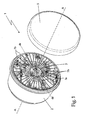
- the inner surface 3i of cup-shaped body 3 has a preferably, though not necessarily made, in bas-relief, first decorative optical pattern which, starting from the bottom of the cup-shaped body 3, is cyclically repeated on the inner surface 3i with a predetermined spatial periodicity; and the automotive light 1 is provided with a neutral and substantially lenticular-shaped, additional optical filter 7 which is made of a transparent or semi-transparent material, and is located below the lenticular half-shell 5, in full or partial coverage of the mouth 3a of cup-shaped body 3, so as to be crossed by the light coming out from the latter.
- the optical filter 7 is furthermore structured so as to have, on one of the two faces, a preferably, though not necessarily, in bas-relief, second decorative optical pattern made which is cyclically repeated on the surface of the optical filter 7 with a predetermined spatial periodicity, and has a shape/ pattern and/or spatial periodicity slightly different from that of the decorative optical pattern present on the inner surface 3i of cup-shaped body 3, so as to cause, in the light coming out from the main cup-shaped body 3, an interferometric effect with Moire deterioration that generates a virtual decorative pattern that having a shape/pattern and a spatial periodicity completely different from those of the decorative optical patterns present, respectively, on the inner surface 3i of cup-shaped body 3 and on the optical filter 7 .
- the optical filter 7 is made of transparent or semitransparent plastic material, optionally also colored; lies on a reference plane locally substantially perpendicular to the longitudinal axis A of cup-shaped body 3; and is dimensioned so as to completely cover the mouth 3a of the cup-shaped body 3, so as to be crossed by the whole light that is generated by the light bulb 4 and comes out of the cup-shaped body 3.
- the optical filter 7 consists of a disc-shaped body made of a transparent or semi-transparent plastic material, optionally also colored, which has a shape complementary to that of the mouth 3a of cup-shaped body 3, and is rigidly fixed to the cup-shaped body 3, so as to lie on a reference plane locally perpendicular to the axis A of the cup-shaped body 3 and be crossed by the whole light coming out of cup-shaped body 3.
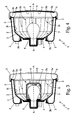
- the inner surface 3i of cup-shaped body 3 is preferably, though not necessarily, provided with a number of radially-oriented longitudinal grooves, depressions or indentations 3b which are angularly equally spaced around the axis A of cup-shaped body 3, and extend towards the mouth 3a of cup-shaped body 3 so as to form a spherical crown with a radially-oriented, regular undulated profile.
- optical filter 7 i.e. the face oriented towards front half-shell 5, instead has a number of transversal grooves, depressions or indentations 7b which are locally tilted with respect to the radial directrix dr of optical filter 7, so as to be locally tilted and misaligned with respect to the longitudinal indentations 3b of the underneath cup-shaped body 3, and are also angularly equally spaced around the reference axis of optical filter 7, i.e.
- rear light 1 is easily deducible from that written above and needs no further explanation. Except to point out that the interferometric effect with Moiré deterioration occurs when the decorative optical patterns present, respectively, on the inner surface 3i of cup-shaped body 3 and on the optical filter 7, have a well-defined spatial distribution with respect to each other, and that the interferometric effect with Moire deterioration allows the external observer to visualize a virtual decorative pattern having a shape and a spatial periodicity completely different from those of the two decorative optical patterns present on the cup-shaped body 3 and on the optical filter 7.
- the benefits deriving from the particular structure of the automotive light 1 are numerous.
- the use of the interferometric effect with Moire deterioration allows the automotive light 1 to produce virtual three-dimensional developed light effects, i.e. virtually provided with depth, which are radically different, and much more visually engaging, than those offered by the currently-installed rear lights on cars.
- the considerable distance between the optical filter 7 and the bottom of the cup-shaped body 3 allows exploiting the effects of parallax to make more realistic the "depth" and three-dimensionality of the light effects produced by the light.
- this particular structure allows the automotive light 1 to change appearance when the light source 4 is turned on. If lighted from the outside, in fact, the automotive light 1 shows the viewer only the optical filter 7, with its relative ornamental pattern.
- the automotive light 1 has production costs that are only slightly higher than those of a traditional automobile light, with all the commercial advantages that this entails.
- the automotive light 1 may be provided with a second lenticular optical filter which can be located immediately above or below the optical filter 7, parallel and facing the optical filter 7, so as to be crossed by the light produced by the light source 4, upstream or downstream of the optical filter 7.
- This second optical filter has an optical surface structured so as to present a third decorative optical pattern which is cyclically repeated with a predetermined spatial periodicity; the shape and/or spatial periodicity of this third decorative optical pattern is different from the shape and/or spatial periodicity of the decorative optical patterns present, respectively, on the inner surface 3i of cup-shaped body 3 and on the optical filter 7, so that the light coming out of cup-shaped body 3 produces, always by interferometric effects with Moire deterioration, a virtual decorative optical pattern different from the decorative optical patterns found on the three elements referred above.
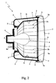
- optical filter 7 may consist of a cap 7 in transparent or semi-transparent material, optionally also colored, which has the shape of a substantially cylindrical bell, extends coaxially to the axis A of cup-shaped body 3 within said cup-shaped body 3, and is fitted directly on the light bulb 4 so as to be first crossed by the light emitted by the light bulb 4.
- the cap 7 in transparent or semi-transparent material is furthermore rigidly fixed on the light socket 6, and has on its inner or outer cylindrical lateral surface a preferably, though not necessarily made, in bas-relief, decorative optical pattern having a predetermined spatial periodicity.
- the outer cylindrical lateral surface of cap 7 has a regular undulated profile, wherein the crests of the waves are parallel to each other and slightly inclined with respect to the longitudinal axis of the cap 7, i.e. slightly inclined with respect to the axis A of the cup-shaped body 3.
- the light that crosses the cap 7 is reflected from the inner surface 3i of the cup-shape body 3 and comes out of the mouth 3a of cup-shaped body 3 generating, due to the interferometric effect with Moire deterioration, a virtual decorative optical pattern which has a shape/design and a spatial periodicity completely different from those of the two decorative optical patterns present, respectively, on the inner surface 3i of the cup-shaped body 3 and on the outer or inner cylindrical lateral surface of the cap 7.
- optical filter 7 may consist of a lenticular body 7 in transparent or semi-transparent material, optionally also colored, which is directly fixed to the lenticular half-shell 5, above the mouth 3a of the cup-shaped body 3.
- the automotive light 1 may also have an electrically-operated, optical-filter moving device 9 which is structured so as to be able to move, on command, the optical filter 7 with respect to the cup-shaped body 3, so as to control the arising of the interferometric effect with Moire deterioration, and/or adjust/vary on command the intensity of the interferometric effect with Moire deterioration.
- an electrically-operated, optical-filter moving device 9 which is structured so as to be able to move, on command, the optical filter 7 with respect to the cup-shaped body 3, so as to control the arising of the interferometric effect with Moire deterioration, and/or adjust/vary on command the intensity of the interferometric effect with Moire deterioration.
- the optical filter 7 consists of a lenticular body 7 in transparent or semi-transparent material, optionally also colored, which is fixed in axially rotating manner on a fifth wheel 10 which, in turn, is rigidly fixed on the mouth 3a of cup-shaped body 3, so as to lie on a reference plane locally perpendicular to the axis A of cup-shaped body 3, and to be coaxial to the axis A of the cup-shaped body 3.
- the fifth wheel 10 can also be fixed on the rear casing 2 or the front half-shell 5, obviously, always above the mouth 3a of cup-shaped body 3.
- the optical filter 7 can then freely rotate around the axis A of cup-shaped body 3, and the optical-filter moving device 9 consists in a small electric motor 9 with permanent magnets or similar, which is preferably, though not necessarily, arranged in the cavity formed by the cup-shaped body 3 inside the rear casing 2, so that its drive shaft protrudes over the mouth 3a of cup-shaped body 3, and can engage a toothed annular crown 9 specifically realized on the periphery of the optical filter 7, so as to be able to rotate the optical filter 7 around the axis A inside the fifth wheel 10, and therefore vary on command the angular position of the optical filter 7 with respect to the cup-shaped body 3.
- a small electric motor 9 with permanent magnets or similar which is preferably, though not necessarily, arranged in the cavity formed by the cup-shaped body 3 inside the rear casing 2, so that its drive shaft protrudes over the mouth 3a of cup-shaped body 3, and can engage a toothed annular crown 9 specifically realized on the periphery of the optical filter 7, so as to be
- the rotation axis of optical filter 7 can also be parallel to and spaced from the axis A of cup-shaped body 3.
- the electric motor 9 can be replaced by another type of electro-mechanical or piezoelectric actuator capable of varying, on command, the angular position of the optical filter 7.
- the moving device 9 has the function to set, on command, the optical filter 7 in the spatial configuration that causes the onset of the interferometric effect with Moire deterioration, but may also be structured so as to rotate, on command and in a continuous manner, the optical filter 7 around the axis A of cup-shaped body 3, so as to move in space without interruption and/or change over time the virtual decorative optical pattern generated by the interferometric effect with Moire deterioration.
- the optical filter 7 consists of a cap 7 in a transparent or semi-transparent material, optionally also colored, which has the shape of a substantially cylindrical bell, extends coaxially to the axis A of cup-shaped body 3 within said cup-shaped body 3, and is fitted directly on the light bulb 4 so as to be first crossed by the light emitted from the light bulb 4.
- the cap 7 made of a transparent or semi-transparent material has, on its inner or outer cylindrical lateral surface, a preferably, though not necessarily, in bas-relief, decorative optical pattern which has a predetermined spatial periodicity, and is fixed in axially rotating manner on a fifth wheel 11 which, in turn, is rigidly fixed on the light socket 6, coaxial to the axis A of cup-shaped body 3.
- a fifth wheel 11 which, in turn, is rigidly fixed on the light socket 6, coaxial to the axis A of cup-shaped body 3.
- the cap 7 can rotate around the axis A of cup-shaped body 3, and is crossed by the light emitted from the light bulb 4.
- the optical-filter moving device 9 consists of a small electric motor 9 with permanent magnets or similar, which is fixed to the light socket 6 next to the light bulb 4, so that its drive shaft protrudes inside the cup-shaped body 3, and can engage a toothed annular crown specifically realized on the periphery of cap 7, so to be able to rotate the cap 7 on the fifth wheel 11 around the axis A, and therefore vary, on command, the angular position of the cap 7 with respect to the cup-shaped body 3.
- the outer cylindrical lateral surface of cap 7 has a regular undulated profile, wherein the crests of the waves are parallel to each other and slightly inclined with respect to the longitudinal axis of the cap 7, i.e. slightly inclined with respect to the axis A of cup-shaped body 3.
- the light that crosses cap 7 is reflected from the inner surface 3i of the cup-shaped body 3 and comes out of the mouth 3a of cup-shaped body 3 generating, due to the interferometric effect with Moire deterioration, a virtual decorative optical pattern which has a shape/pattern and a spatial periodicity completely different from those of the two decorative optical patterns present, respectively, on the inner surface 3i of the cup-shaped body 3 and on the outer or inner cylindrical side surface of the cap 7.
- the moving device 9 has the function to provide, on command, the cap 7 in the spatial configuration that causes the onset of the interferometric effect with Moire deterioration, but may also be structured so as to rotate, on command and in a continuative way, the cap 7 around the axis A of cup-shaped body 3, so as to move in space without interruption and/or change over time the virtual decorative optical pattern generated by the interferometric effect with Moire deterioration.
Landscapes
- Engineering & Computer Science (AREA)
- General Engineering & Computer Science (AREA)
- Optical Elements Other Than Lenses (AREA)
- Arrangements Of Lighting Devices For Vehicle Interiors, Mounting And Supporting Thereof, Circuits Therefore (AREA)
- Non-Portable Lighting Devices Or Systems Thereof (AREA)
Claims (10)
- Kraftfahrzeuglicht (1), mindestens einen napfförmigen Hauptkörper (3), dessen innere Oberfläche (3i) so strukturiert ist, dass sie das auftreffende Licht in Richtung der Mündung (3a) desselben napfförmigen Hauptkörpers (3) lenkt, und mindestens eine Lichtquelle (4) aufweisend, die sich innerhalb des napfförmigen Hauptkörpers (3) befindet und so strukturiert ist, dass sie Licht aussendet, wenn Strom eingeschaltet wird; wobei die innere Oberfläche (3i) des napfförmigen Hauptkörpers (3) mit einem ersten optischen Ziermuster versehen ist, das auf der inneren Oberfläche (3i) mit einer vorbestimmten räumlichen Periodizität zyklisch wiederholt wird, wobei das Kraftfahrzeuglicht (1) dadurch gekennzeichnet ist, dass es ferner mindestens ein zusätzliches optisches Filter (7) aufweist, das aus einem transparenten oder halbtransparenten Material hergestellt und so angeordnet ist, dass es von dem von der Lichtquelle (4) erzeugten Licht durchquert wird; wobei das mindestens eine zusätzliche optische Filter (7) mit einer optischen Oberfläche versehen ist, die so strukturiert ist, dass sie ein zweites optisches Ziermuster, das mit einer vorbestimmten räumlichen Periodizität zyklisch wiederholt wird, besitzt; wobei die Form und/oder räumliche Periodizität des optischen Ziermusters auf dem zusätzlichen optischen Filter (7) von der Form und/oder räumlichen Periodizität des optischen Ziermusters auf dem napfförmigen Hauptkörper (3) verschieden ist/sind und von solcher Art ist/sind, dass in dem aus dem napfförmigen Hauptkörper (3) kommenden Licht ein Interferenzeffekt mit Moiré-Störung verursacht wird, der ein virtuelles, optisches Ziermuster, das von den optischen Ziermustern auf dem napfförmigen Hauptkörper (3) und auf dem zusätzlichen optischen Filter (7) verschieden ist, erzeugt.
- Kraftfahrzeuglicht nach Anspruch 1, dadurch gekennzeichnet, dass die innere Oberfläche (3i) des napfförmigen Hauptkörpers (3) spiegelartig behandelt ist, um das auftreffende Licht in Richtung der Mündung (3a) desselben napfförmigen Hauptkörpers (3) zu reflektieren.
- Kraftfahrzeuglicht nach Anspruch 1 oder 2, dadurch gekennzeichnet, dass das optische Filter (7) im Wesentlichen die Form einer Linse hat und sich im Wesentlichen an der Mündung (3a) des napfförmigen Hauptkörpers (3) befindet, sodass es von dem Licht, das von dort austritt, durchquert wird.
- Kraftfahrzeuglicht nach Anspruch 1 oder 2, dadurch gekennzeichnet, dass das optische Filter (7) aus einer aus einem transparenten oder halbtransparenten Material hergestellten Kappe (7) besteht, die im Wesentlichen glockenförmig ist und so an der Lichtquelle (4) befestigt ist, dass es von dem von Letzterer ausgesendeten Licht durchquert wird.
- Kraftfahrzeuglicht nach Anspruch 4, dadurch gekennzeichnet, dass die aus einem transparenten oder halbtransparenten Material hergestellte Kappe (7) die Form einer im Wesentlichen zylindrischen Glocke hat und mit der Längsachse (A) des napfförmigen Hauptkörpers (3) im Wesentlichen achsgleich angeordnet ist.
- Kraftfahrzeuglicht nach einem der vorangegangenen Ansprüche, dadurch gekennzeichnet, dass es ferner elektrisch betätigte, bewegende Mittel (9) aufweist, die für das Bewegen, auf Befehl, des mindestens einen zusätzlichen optischen Filters (7) in Bezug auf den napfförmigen Körper (3) strukturiert sind.
- Kraftfahrzeuglicht nach Anspruch 6, dadurch gekennzeichnet, dass das mindestens eine optische Filter (7) fähig ist, um eine vorbestimmte Bezugsachse (A) zu drehen, und dadurch, dass die bewegenden Mittel (9) strukturiert sind, um jenes optische Filter (7) um die Bezugsachse (A) zu drehen.
- Kraftfahrzeuglicht nach Anspruch 7, dadurch gekennzeichnet, dass die Bezugsachse (A) lokal im Wesentlichen mit der Längsachse (A) des napfförmigen Hauptkörpers (3) zusammenfällt.
- Kraftfahrzeuglicht nach einem der vorangegangenen Ansprüche, dadurch gekennzeichnet, dass es ferner aufweist:- ein im Wesentlichen beckenförmiges, starres, hinteres Gehäuse (2), das so strukturiert ist, dass es in einen eigens in der Fahrzeugkarosserie hergestellten Ausschnitt versenkt ist; und- eine vordere Linsenscheiben-Halbschale (5), die mindestens teilweise aus einem transparenten oder halbtransparenten Material hergestellt ist und die angeordnet wird, um die Mündung (2a) des starren, hinteren Gehäuses (2) zu schließen;wobei der mindestens eine napfförmige Hauptkörper (3) sich im Inneren des starren, hinteren Gehäuses (2) befindet, während die Mündung (3a) des napfförmigen Hauptkörpers (3) der vorderen Linsenscheiben-Halbschale (5) zugewandt ist.
- Kraftfahrzeuglicht nach den Ansprüchen 3 und 9, dadurch gekennzeichnet, dass das zusätzliche optische Filter (7) an der vorderen Linsenscheiben-Halbschale (5) unmittelbar über der Mündung (3a) des napfförmigen Hauptkörpers (3) befestigt ist.
Priority Applications (1)
| Application Number | Priority Date | Filing Date | Title |
|---|---|---|---|
| PL11760548T PL2598792T3 (pl) | 2010-07-26 | 2011-07-26 | Światło samochodowe |
Applications Claiming Priority (2)
| Application Number | Priority Date | Filing Date | Title |
|---|---|---|---|
| ITTV2010A000105A IT1401232B1 (it) | 2010-07-26 | 2010-07-26 | Fanale automobilistico |
| PCT/IB2011/001728 WO2012014044A1 (en) | 2010-07-26 | 2011-07-26 | Automotive light |
Publications (2)
| Publication Number | Publication Date |
|---|---|
| EP2598792A1 EP2598792A1 (de) | 2013-06-05 |
| EP2598792B1 true EP2598792B1 (de) | 2015-04-22 |
Family
ID=43529987
Family Applications (1)
| Application Number | Title | Priority Date | Filing Date |
|---|---|---|---|
| EP20110760548 Not-in-force EP2598792B1 (de) | 2010-07-26 | 2011-07-26 | Kraftfahrzeuglicht |
Country Status (5)
| Country | Link |
|---|---|
| EP (1) | EP2598792B1 (de) |
| ES (1) | ES2540115T3 (de) |
| IT (1) | IT1401232B1 (de) |
| PL (1) | PL2598792T3 (de) |
| WO (1) | WO2012014044A1 (de) |
Families Citing this family (1)
| Publication number | Priority date | Publication date | Assignee | Title |
|---|---|---|---|---|
| FR3121500B1 (fr) * | 2021-03-30 | 2023-05-19 | Marelli Automotive Lighting France | Dispositif lumineux pour un véhicule automobile apte à créer un effet optique connu sous le nom de moiré. |
Family Cites Families (5)
| Publication number | Priority date | Publication date | Assignee | Title |
|---|---|---|---|---|
| SE402644B (sv) * | 1976-10-15 | 1978-07-10 | Bergkvist Lars A | Anordning for att instella ett foremal till att intaga en forutbestemd vinkel mot ett visst plan |
| FR2530781A1 (fr) * | 1982-07-23 | 1984-01-27 | Cibie Projecteurs | Feux notamment destines aux vehicules automobiles |
| JPH0439854A (ja) * | 1990-06-04 | 1992-02-10 | Toshiba Lighting & Technol Corp | 照明装置 |
| US5258895A (en) * | 1992-03-09 | 1993-11-02 | Bosse Thomas W | Moire light assembly |
| US20050225998A1 (en) * | 2004-04-09 | 2005-10-13 | Shigeru Komori | Light for vehicles |
-
2010
- 2010-07-26 IT ITTV2010A000105A patent/IT1401232B1/it active
-
2011
- 2011-07-26 PL PL11760548T patent/PL2598792T3/pl unknown
- 2011-07-26 WO PCT/IB2011/001728 patent/WO2012014044A1/en not_active Ceased
- 2011-07-26 EP EP20110760548 patent/EP2598792B1/de not_active Not-in-force
- 2011-07-26 ES ES11760548.5T patent/ES2540115T3/es active Active
Also Published As
| Publication number | Publication date |
|---|---|
| WO2012014044A1 (en) | 2012-02-02 |
| ITTV20100105A1 (it) | 2012-01-27 |
| IT1401232B1 (it) | 2013-07-12 |
| ES2540115T3 (es) | 2015-07-08 |
| PL2598792T3 (pl) | 2016-01-29 |
| WO2012014044A8 (en) | 2012-04-12 |
| EP2598792A1 (de) | 2013-06-05 |
Similar Documents
| Publication | Publication Date | Title |
|---|---|---|
| WO2012052946A1 (en) | Automotive light | |
| CN107921905B (zh) | 用于车辆的照明装置 | |
| CA2644876C (en) | Dynamic three dimensional effect lamp assembly | |
| EP3783259B1 (de) | Beleuchtungsvorrichtung für ein fahrzeug | |
| US20040136203A1 (en) | Indicating and/or lighting device of the headlamp type for a motor vehicle | |
| KR20130081352A (ko) | 차량용 램프 | |
| JP5789628B2 (ja) | 灯具 | |
| CN103635741A (zh) | 车灯元件 | |
| CN109312905A (zh) | 具有导光板的汽车照明单元 | |
| JP2016164875A (ja) | 自動車両用照明装置 | |
| EP3263980B1 (de) | Fahrzeugleuchte mit einem abschnitt zur lichtemission mit opalisierendem effekt | |
| JP6015722B2 (ja) | 表示装置 | |
| EP2598792B1 (de) | Kraftfahrzeuglicht | |
| EP2413022B1 (de) | Kraftfahrzeuglicht | |
| CN105444084A (zh) | 汽车信号灯 | |
| JP2009064774A (ja) | ランプ器具 | |
| JP2014160621A (ja) | 車両用灯具、車両用アウトサイドミラー装置 | |
| JP5301326B2 (ja) | ドアミラーターンランプ | |
| JP2007207667A (ja) | 灯具 | |
| TWM310827U (en) | Car indicator light with light-conducting function | |
| JP2010257693A (ja) | 車両用灯具 | |
| JP5576249B2 (ja) | 車両用灯具 | |
| JP2009134879A (ja) | 照明装置 | |
| JP4395401B2 (ja) | 車両用灯具のリフレクタ | |
| JP2014112473A (ja) | 車両用信号灯 |
Legal Events
| Date | Code | Title | Description |
|---|---|---|---|
| PUAI | Public reference made under article 153(3) epc to a published international application that has entered the european phase |
Free format text: ORIGINAL CODE: 0009012 |
|
| 17P | Request for examination filed |
Effective date: 20130117 |
|
| AK | Designated contracting states |
Kind code of ref document: A1 Designated state(s): AL AT BE BG CH CY CZ DE DK EE ES FI FR GB GR HR HU IE IS IT LI LT LU LV MC MK MT NL NO PL PT RO RS SE SI SK SM TR |
|
| DAX | Request for extension of the european patent (deleted) | ||
| REG | Reference to a national code |
Ref country code: DE Ref legal event code: R079 Ref document number: 602011015956 Country of ref document: DE Free format text: PREVIOUS MAIN CLASS: F21S0010000000 Ipc: F21S0008100000 |
|
| GRAP | Despatch of communication of intention to grant a patent |
Free format text: ORIGINAL CODE: EPIDOSNIGR1 |
|
| RIC1 | Information provided on ipc code assigned before grant |
Ipc: F21S 8/10 20060101AFI20141027BHEP |
|
| INTG | Intention to grant announced |
Effective date: 20141119 |
|
| GRAS | Grant fee paid |
Free format text: ORIGINAL CODE: EPIDOSNIGR3 |
|
| GRAA | (expected) grant |
Free format text: ORIGINAL CODE: 0009210 |
|
| AK | Designated contracting states |
Kind code of ref document: B1 Designated state(s): AL AT BE BG CH CY CZ DE DK EE ES FI FR GB GR HR HU IE IS IT LI LT LU LV MC MK MT NL NO PL PT RO RS SE SI SK SM TR |
|
| REG | Reference to a national code |
Ref country code: GB Ref legal event code: FG4D |
|
| REG | Reference to a national code |
Ref country code: CH Ref legal event code: EP |
|
| REG | Reference to a national code |
Ref country code: AT Ref legal event code: REF Ref document number: 723458 Country of ref document: AT Kind code of ref document: T Effective date: 20150515 |
|
| REG | Reference to a national code |
Ref country code: IE Ref legal event code: FG4D |
|
| REG | Reference to a national code |
Ref country code: DE Ref legal event code: R096 Ref document number: 602011015956 Country of ref document: DE Effective date: 20150603 |
|
| REG | Reference to a national code |
Ref country code: ES Ref legal event code: FG2A Ref document number: 2540115 Country of ref document: ES Kind code of ref document: T3 Effective date: 20150708 |
|
| REG | Reference to a national code |
Ref country code: NL Ref legal event code: VDEP Effective date: 20150422 |
|
| REG | Reference to a national code |
Ref country code: AT Ref legal event code: MK05 Ref document number: 723458 Country of ref document: AT Kind code of ref document: T Effective date: 20150422 |
|
| REG | Reference to a national code |
Ref country code: LT Ref legal event code: MG4D |
|
| PG25 | Lapsed in a contracting state [announced via postgrant information from national office to epo] |
Ref country code: NL Free format text: LAPSE BECAUSE OF FAILURE TO SUBMIT A TRANSLATION OF THE DESCRIPTION OR TO PAY THE FEE WITHIN THE PRESCRIBED TIME-LIMIT Effective date: 20150422 |
|
| PG25 | Lapsed in a contracting state [announced via postgrant information from national office to epo] |
Ref country code: HR Free format text: LAPSE BECAUSE OF FAILURE TO SUBMIT A TRANSLATION OF THE DESCRIPTION OR TO PAY THE FEE WITHIN THE PRESCRIBED TIME-LIMIT Effective date: 20150422 Ref country code: PT Free format text: LAPSE BECAUSE OF FAILURE TO SUBMIT A TRANSLATION OF THE DESCRIPTION OR TO PAY THE FEE WITHIN THE PRESCRIBED TIME-LIMIT Effective date: 20150824 Ref country code: NO Free format text: LAPSE BECAUSE OF FAILURE TO SUBMIT A TRANSLATION OF THE DESCRIPTION OR TO PAY THE FEE WITHIN THE PRESCRIBED TIME-LIMIT Effective date: 20150722 Ref country code: FI Free format text: LAPSE BECAUSE OF FAILURE TO SUBMIT A TRANSLATION OF THE DESCRIPTION OR TO PAY THE FEE WITHIN THE PRESCRIBED TIME-LIMIT Effective date: 20150422 Ref country code: LT Free format text: LAPSE BECAUSE OF FAILURE TO SUBMIT A TRANSLATION OF THE DESCRIPTION OR TO PAY THE FEE WITHIN THE PRESCRIBED TIME-LIMIT Effective date: 20150422 |
|
| REG | Reference to a national code |
Ref country code: FR Ref legal event code: PLFP Year of fee payment: 5 |
|
| PG25 | Lapsed in a contracting state [announced via postgrant information from national office to epo] |
Ref country code: GR Free format text: LAPSE BECAUSE OF FAILURE TO SUBMIT A TRANSLATION OF THE DESCRIPTION OR TO PAY THE FEE WITHIN THE PRESCRIBED TIME-LIMIT Effective date: 20150723 Ref country code: LV Free format text: LAPSE BECAUSE OF FAILURE TO SUBMIT A TRANSLATION OF THE DESCRIPTION OR TO PAY THE FEE WITHIN THE PRESCRIBED TIME-LIMIT Effective date: 20150422 Ref country code: AT Free format text: LAPSE BECAUSE OF FAILURE TO SUBMIT A TRANSLATION OF THE DESCRIPTION OR TO PAY THE FEE WITHIN THE PRESCRIBED TIME-LIMIT Effective date: 20150422 Ref country code: RS Free format text: LAPSE BECAUSE OF FAILURE TO SUBMIT A TRANSLATION OF THE DESCRIPTION OR TO PAY THE FEE WITHIN THE PRESCRIBED TIME-LIMIT Effective date: 20150422 Ref country code: IS Free format text: LAPSE BECAUSE OF FAILURE TO SUBMIT A TRANSLATION OF THE DESCRIPTION OR TO PAY THE FEE WITHIN THE PRESCRIBED TIME-LIMIT Effective date: 20150822 |
|
| REG | Reference to a national code |
Ref country code: DE Ref legal event code: R097 Ref document number: 602011015956 Country of ref document: DE |
|
| PG25 | Lapsed in a contracting state [announced via postgrant information from national office to epo] |
Ref country code: DK Free format text: LAPSE BECAUSE OF FAILURE TO SUBMIT A TRANSLATION OF THE DESCRIPTION OR TO PAY THE FEE WITHIN THE PRESCRIBED TIME-LIMIT Effective date: 20150422 Ref country code: EE Free format text: LAPSE BECAUSE OF FAILURE TO SUBMIT A TRANSLATION OF THE DESCRIPTION OR TO PAY THE FEE WITHIN THE PRESCRIBED TIME-LIMIT Effective date: 20150422 |
|
| PLBE | No opposition filed within time limit |
Free format text: ORIGINAL CODE: 0009261 |
|
| STAA | Information on the status of an ep patent application or granted ep patent |
Free format text: STATUS: NO OPPOSITION FILED WITHIN TIME LIMIT |
|
| PG25 | Lapsed in a contracting state [announced via postgrant information from national office to epo] |
Ref country code: SK Free format text: LAPSE BECAUSE OF FAILURE TO SUBMIT A TRANSLATION OF THE DESCRIPTION OR TO PAY THE FEE WITHIN THE PRESCRIBED TIME-LIMIT Effective date: 20150422 Ref country code: MC Free format text: LAPSE BECAUSE OF FAILURE TO SUBMIT A TRANSLATION OF THE DESCRIPTION OR TO PAY THE FEE WITHIN THE PRESCRIBED TIME-LIMIT Effective date: 20150422 Ref country code: RO Free format text: LAPSE BECAUSE OF NON-PAYMENT OF DUE FEES Effective date: 20150422 |
|
| REG | Reference to a national code |
Ref country code: CH Ref legal event code: PL |
|
| GBPC | Gb: european patent ceased through non-payment of renewal fee |
Effective date: 20150726 |
|
| 26N | No opposition filed |
Effective date: 20160125 |
|
| PG25 | Lapsed in a contracting state [announced via postgrant information from national office to epo] |
Ref country code: LU Free format text: LAPSE BECAUSE OF FAILURE TO SUBMIT A TRANSLATION OF THE DESCRIPTION OR TO PAY THE FEE WITHIN THE PRESCRIBED TIME-LIMIT Effective date: 20150726 |
|
| REG | Reference to a national code |
Ref country code: IE Ref legal event code: MM4A |
|
| PG25 | Lapsed in a contracting state [announced via postgrant information from national office to epo] |
Ref country code: GB Free format text: LAPSE BECAUSE OF NON-PAYMENT OF DUE FEES Effective date: 20150726 Ref country code: CH Free format text: LAPSE BECAUSE OF NON-PAYMENT OF DUE FEES Effective date: 20150731 Ref country code: LI Free format text: LAPSE BECAUSE OF NON-PAYMENT OF DUE FEES Effective date: 20150731 |
|
| PG25 | Lapsed in a contracting state [announced via postgrant information from national office to epo] |
Ref country code: SI Free format text: LAPSE BECAUSE OF FAILURE TO SUBMIT A TRANSLATION OF THE DESCRIPTION OR TO PAY THE FEE WITHIN THE PRESCRIBED TIME-LIMIT Effective date: 20150422 |
|
| REG | Reference to a national code |
Ref country code: FR Ref legal event code: PLFP Year of fee payment: 6 |
|
| PG25 | Lapsed in a contracting state [announced via postgrant information from national office to epo] |
Ref country code: IE Free format text: LAPSE BECAUSE OF NON-PAYMENT OF DUE FEES Effective date: 20150726 |
|
| PG25 | Lapsed in a contracting state [announced via postgrant information from national office to epo] |
Ref country code: BE Free format text: LAPSE BECAUSE OF FAILURE TO SUBMIT A TRANSLATION OF THE DESCRIPTION OR TO PAY THE FEE WITHIN THE PRESCRIBED TIME-LIMIT Effective date: 20150422 |
|
| PG25 | Lapsed in a contracting state [announced via postgrant information from national office to epo] |
Ref country code: MT Free format text: LAPSE BECAUSE OF FAILURE TO SUBMIT A TRANSLATION OF THE DESCRIPTION OR TO PAY THE FEE WITHIN THE PRESCRIBED TIME-LIMIT Effective date: 20150422 |
|
| PG25 | Lapsed in a contracting state [announced via postgrant information from national office to epo] |
Ref country code: HU Free format text: LAPSE BECAUSE OF FAILURE TO SUBMIT A TRANSLATION OF THE DESCRIPTION OR TO PAY THE FEE WITHIN THE PRESCRIBED TIME-LIMIT; INVALID AB INITIO Effective date: 20110726 Ref country code: SM Free format text: LAPSE BECAUSE OF FAILURE TO SUBMIT A TRANSLATION OF THE DESCRIPTION OR TO PAY THE FEE WITHIN THE PRESCRIBED TIME-LIMIT Effective date: 20150422 Ref country code: BG Free format text: LAPSE BECAUSE OF FAILURE TO SUBMIT A TRANSLATION OF THE DESCRIPTION OR TO PAY THE FEE WITHIN THE PRESCRIBED TIME-LIMIT Effective date: 20150422 |
|
| REG | Reference to a national code |
Ref country code: FR Ref legal event code: PLFP Year of fee payment: 7 |
|
| PG25 | Lapsed in a contracting state [announced via postgrant information from national office to epo] |
Ref country code: CY Free format text: LAPSE BECAUSE OF FAILURE TO SUBMIT A TRANSLATION OF THE DESCRIPTION OR TO PAY THE FEE WITHIN THE PRESCRIBED TIME-LIMIT Effective date: 20150422 Ref country code: SE Free format text: LAPSE BECAUSE OF FAILURE TO SUBMIT A TRANSLATION OF THE DESCRIPTION OR TO PAY THE FEE WITHIN THE PRESCRIBED TIME-LIMIT Effective date: 20150422 |
|
| REG | Reference to a national code |
Ref country code: DE Ref legal event code: R079 Ref document number: 602011015956 Country of ref document: DE Free format text: PREVIOUS MAIN CLASS: F21S0008100000 Ipc: F21S0043000000 |
|
| REG | Reference to a national code |
Ref country code: FR Ref legal event code: PLFP Year of fee payment: 8 |
|
| PG25 | Lapsed in a contracting state [announced via postgrant information from national office to epo] |
Ref country code: MK Free format text: LAPSE BECAUSE OF FAILURE TO SUBMIT A TRANSLATION OF THE DESCRIPTION OR TO PAY THE FEE WITHIN THE PRESCRIBED TIME-LIMIT Effective date: 20150422 |
|
| PGFP | Annual fee paid to national office [announced via postgrant information from national office to epo] |
Ref country code: CZ Payment date: 20180625 Year of fee payment: 8 |
|
| PGFP | Annual fee paid to national office [announced via postgrant information from national office to epo] |
Ref country code: PL Payment date: 20180621 Year of fee payment: 8 Ref country code: IT Payment date: 20180620 Year of fee payment: 8 Ref country code: FR Payment date: 20180621 Year of fee payment: 8 |
|
| PG25 | Lapsed in a contracting state [announced via postgrant information from national office to epo] |
Ref country code: AL Free format text: LAPSE BECAUSE OF FAILURE TO SUBMIT A TRANSLATION OF THE DESCRIPTION OR TO PAY THE FEE WITHIN THE PRESCRIBED TIME-LIMIT Effective date: 20150422 |
|
| PGFP | Annual fee paid to national office [announced via postgrant information from national office to epo] |
Ref country code: ES Payment date: 20180801 Year of fee payment: 8 Ref country code: DE Payment date: 20180620 Year of fee payment: 8 |
|
| PGFP | Annual fee paid to national office [announced via postgrant information from national office to epo] |
Ref country code: TR Payment date: 20180704 Year of fee payment: 8 |
|
| REG | Reference to a national code |
Ref country code: DE Ref legal event code: R119 Ref document number: 602011015956 Country of ref document: DE |
|
| PG25 | Lapsed in a contracting state [announced via postgrant information from national office to epo] |
Ref country code: DE Free format text: LAPSE BECAUSE OF NON-PAYMENT OF DUE FEES Effective date: 20200201 |
|
| PG25 | Lapsed in a contracting state [announced via postgrant information from national office to epo] |
Ref country code: CZ Free format text: LAPSE BECAUSE OF NON-PAYMENT OF DUE FEES Effective date: 20190726 |
|
| PG25 | Lapsed in a contracting state [announced via postgrant information from national office to epo] |
Ref country code: FR Free format text: LAPSE BECAUSE OF NON-PAYMENT OF DUE FEES Effective date: 20190731 |
|
| PG25 | Lapsed in a contracting state [announced via postgrant information from national office to epo] |
Ref country code: IT Free format text: LAPSE BECAUSE OF NON-PAYMENT OF DUE FEES Effective date: 20190726 |
|
| REG | Reference to a national code |
Ref country code: ES Ref legal event code: FD2A Effective date: 20201201 |
|
| PG25 | Lapsed in a contracting state [announced via postgrant information from national office to epo] |
Ref country code: ES Free format text: LAPSE BECAUSE OF NON-PAYMENT OF DUE FEES Effective date: 20190727 |
|
| PG25 | Lapsed in a contracting state [announced via postgrant information from national office to epo] |
Ref country code: PL Free format text: LAPSE BECAUSE OF NON-PAYMENT OF DUE FEES Effective date: 20190726 |
|
| PG25 | Lapsed in a contracting state [announced via postgrant information from national office to epo] |
Ref country code: TR Free format text: LAPSE BECAUSE OF NON-PAYMENT OF DUE FEES Effective date: 20190726 |