EP2413022B1 - Kraftfahrzeuglicht - Google Patents
Kraftfahrzeuglicht Download PDFInfo
- Publication number
- EP2413022B1 EP2413022B1 EP11175465.1A EP11175465A EP2413022B1 EP 2413022 B1 EP2413022 B1 EP 2413022B1 EP 11175465 A EP11175465 A EP 11175465A EP 2413022 B1 EP2413022 B1 EP 2413022B1
- Authority
- EP
- European Patent Office
- Prior art keywords
- shaped body
- light
- cup
- main cup
- mouth
- Prior art date
- Legal status (The legal status is an assumption and is not a legal conclusion. Google has not performed a legal analysis and makes no representation as to the accuracy of the status listed.)
- Not-in-force
Links
- 230000003287 optical effect Effects 0.000 claims description 98
- 230000000694 effects Effects 0.000 claims description 20
- 230000006866 deterioration Effects 0.000 claims description 18
- 239000012780 transparent material Substances 0.000 claims description 9
- 230000005611 electricity Effects 0.000 claims description 3
- 239000000463 material Substances 0.000 description 14
- 229920003023 plastic Polymers 0.000 description 9
- 230000001795 light effect Effects 0.000 description 6
- 239000004033 plastic Substances 0.000 description 6
- 238000001746 injection moulding Methods 0.000 description 3
- 230000000737 periodic effect Effects 0.000 description 2
- 230000000295 complement effect Effects 0.000 description 1
- 230000005489 elastic deformation Effects 0.000 description 1
- 238000003384 imaging method Methods 0.000 description 1
- 238000004519 manufacturing process Methods 0.000 description 1
- 239000007769 metal material Substances 0.000 description 1
- 230000007935 neutral effect Effects 0.000 description 1
- 229920003229 poly(methyl methacrylate) Polymers 0.000 description 1
- 239000004417 polycarbonate Substances 0.000 description 1
- 229920000515 polycarbonate Polymers 0.000 description 1
- 239000004926 polymethyl methacrylate Substances 0.000 description 1
- 238000001228 spectrum Methods 0.000 description 1
- 238000011144 upstream manufacturing Methods 0.000 description 1
Images


Classifications
-
- F—MECHANICAL ENGINEERING; LIGHTING; HEATING; WEAPONS; BLASTING
- F21—LIGHTING
- F21S—NON-PORTABLE LIGHTING DEVICES; SYSTEMS THEREOF; VEHICLE LIGHTING DEVICES SPECIALLY ADAPTED FOR VEHICLE EXTERIORS
- F21S43/00—Signalling devices specially adapted for vehicle exteriors, e.g. brake lamps, direction indicator lights or reversing lights
- F21S43/40—Signalling devices specially adapted for vehicle exteriors, e.g. brake lamps, direction indicator lights or reversing lights characterised by the combination of reflectors and refractors
-
- F—MECHANICAL ENGINEERING; LIGHTING; HEATING; WEAPONS; BLASTING
- F21—LIGHTING
- F21S—NON-PORTABLE LIGHTING DEVICES; SYSTEMS THEREOF; VEHICLE LIGHTING DEVICES SPECIALLY ADAPTED FOR VEHICLE EXTERIORS
- F21S43/00—Signalling devices specially adapted for vehicle exteriors, e.g. brake lamps, direction indicator lights or reversing lights
- F21S43/20—Signalling devices specially adapted for vehicle exteriors, e.g. brake lamps, direction indicator lights or reversing lights characterised by refractors, transparent cover plates, light guides or filters
- F21S43/255—Filters
-
- F—MECHANICAL ENGINEERING; LIGHTING; HEATING; WEAPONS; BLASTING
- F21—LIGHTING
- F21S—NON-PORTABLE LIGHTING DEVICES; SYSTEMS THEREOF; VEHICLE LIGHTING DEVICES SPECIALLY ADAPTED FOR VEHICLE EXTERIORS
- F21S43/00—Signalling devices specially adapted for vehicle exteriors, e.g. brake lamps, direction indicator lights or reversing lights
- F21S43/30—Signalling devices specially adapted for vehicle exteriors, e.g. brake lamps, direction indicator lights or reversing lights characterised by reflectors
- F21S43/33—Signalling devices specially adapted for vehicle exteriors, e.g. brake lamps, direction indicator lights or reversing lights characterised by reflectors characterised by their material, surface treatment or coatings
-
- F—MECHANICAL ENGINEERING; LIGHTING; HEATING; WEAPONS; BLASTING
- F21—LIGHTING
- F21S—NON-PORTABLE LIGHTING DEVICES; SYSTEMS THEREOF; VEHICLE LIGHTING DEVICES SPECIALLY ADAPTED FOR VEHICLE EXTERIORS
- F21S43/00—Signalling devices specially adapted for vehicle exteriors, e.g. brake lamps, direction indicator lights or reversing lights
- F21S43/10—Signalling devices specially adapted for vehicle exteriors, e.g. brake lamps, direction indicator lights or reversing lights characterised by the light source
- F21S43/13—Signalling devices specially adapted for vehicle exteriors, e.g. brake lamps, direction indicator lights or reversing lights characterised by the light source characterised by the type of light source
- F21S43/14—Light emitting diodes [LED]
Definitions
- the present invention relates to an automotive light.
- the present invention relates to a rear light for cars, use to which the following description refers purely by way of example without implying any loss of generality.
- the car rear lights are usually made up of a substantially basin-shaped, rigid rear casing which is structured so as to be permanently recessed into a compartment specifically made in the rear portion of the vehicle body; of at least one cup-shaped body of substantially parabolic profile, which is located inside the rear casing with the concave side facing the mouth of the rear casing, and has a mirror-finished inner surface so as to reflect the incident light towards the mouth; of a light source which is placed close to the bottom of the cup-shaped body, and is structured so as to emit light when electricity powered; and of a front lenticular half-shell which is at least partially made of a transparent or semi-transparent, also possibly colored, plastic material and is arranged to close the mouth of the casing so as to emerge to the outside of the vehicle body and be crossed by the light emitted from the light source underneath.
- a front lenticular half-shell which is at least partially made of a transparent or semi-transparent, also possibly colored, plastic material and is arranged to close the mouth of the casing so as
- the front lenticular half-shell is provided with at least one transparent or semi-transparent, usually colored, portion, and is positioned immediately over the body of the reflecting cup and, according to the features of the light beam that the light must emit, may be shaped so as to have clear surfaces which do not significantly modify the propagation of light and/or optical surfaces having the function of either scattering or concentrating the light produced by the light source underneath.
- the light effects produced by the rear light are used to give greater visibility and distinctive capacity to the car having said light installed.
- US5258895 discloses an automotive light implementing an interferometric effect with Moiré deterioration which generates a virtual decorative optical pattern.
- Aim of the present invention is to make a rear light for cars, motor vehicles and the like, which is capable of producing, via an interferometric effect with Moiré deterioration, new aesthetically engaging and innovative light effects greater than those currently known.
- an automotive light as specified in Claim 1 and preferably, though not necessarily, in any one of the dependant claims.
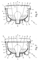
- referral numeral 1 indicates as a whole an automotive light specially structured to be fixed on the front or rear part of the vehicle body of a car or other vehicle.
- the automotive light 1 is preferably, though not necessarily, structured to be fixed on the rear part of the car body, and comprises:
- cup-shaped body 3 is preferably, though not necessarily, metalized or otherwise mirror-finished, so as to reflect the incident light towards the mouth 3a of cup-shaped body 3 and, therefore, towards the mouth 2a of rear casing 2.
- Automatic light 1 is further provided with a front lenticular half-shell 5 at least partially made of a transparent or semi-transparent material, and which is arranged to close the mouth 2a of the rear casing 2 so as to surface from the outside of the vehicle body (not shown) and be crossed by the light emitted by the light source 4.
- the cup-shaped body 3 is thus positioned in the rear casing 2 with the mouth 3a facing the lenticular half-shell 5.
- the lenticular half-shell 5 is provided with at least one transparent or semi-transparent, and optionally also colored, portion, and is arranged to close the mouth 2a of rear casing 2, so that its transparent or semi-transparent portion is crossed by at least part of the light that is emitted by the light source 4 and is reflected towards the mouth 2a of the casing 2a of the cup-shaped body 3.
- automotive light 1 is preferably, though not necessarily, provided with only one cup-shaped body 3 completely recessed inside the rear casing 2; while the lenticular half-shell 5 is preferably, though not necessarily, made entirely of a transparent or semi-transparent plastic material, optionally also colored, such as polycarbonate or polymethyl methacrylate.
- cup-shaped body 3 is preferably, though not necessarily, made of an opaque plastic material via an injection molding process, and has the inner surface 3i mirror-metalized so as to reflect the incident light.
- the bottom of cup-shaped body 3 is furthermore rigidly anchored to the bottom of rear casing 2 by means of pass-through screws that pass in sequence both elements.
- the rear casing 2 is preferably, though not necessarily, made of an opaque plastic material via an injection molding process, and is provided with a number of protruding fixing appendixes in plastic and/or metal material.
- cup-shaped body 3 can be made in one piece with the rear casing 2 preferably, though not necessarily, via an injection molding process.
- light source 4 instead preferably, though not necessarily, consists in a incandescent light bulb 4 or similar which is fitted in removable manner into a light socket 6 which, in turn, is structured so as to be inserted and then locked in a rigid and stable, though easily releasable, manner within a pass-through hole 6a specifically realized on the bottom of cup-shaped body 3, so as to allow the light bulb 4 to protrude into the cup-shaped body 3 while keeping said bulb substantially coaxial to the longitudinal axis A of the cup-shaped body 3.
- the automotive light 1 is also provided with two substantially lenticular-shaped, neutral optical filters 7 and 8 which are made of transparent or semi-transparent material and are arranged one on top of the other, immediately underneath the lenticular half-shell 5, so as to be parallel and faced one other and to either partially or completely cover the mouth 3a of the cup-shaped body 3 for being crossed by the light coming out from the latter.
- the optical filters 7 and 8 are made of transparent or semi-transparent, optionally also colored, plastic material; lay on reference planes locally and substantially perpendicular to the longitudinal axis A of cup-shaped body 3; and are dimensioned so as to completely cover the mouth 3a of the cup-shaped body 3, so as to be crossed by the whole of the light which is produced by the light bulb 4 and comes out from cup-shaped body 3.
- Each optical filter 7, 8 is furthermore structured so as to have, on one of the two faces, a decorative preferably, though not necessarily, bas-relief optical pattern which is cyclically repeated on surface of the optical filter 7 or 8 with a predetermined spatial periodicity.
- the decorative optical pattern on the optical filter 7 has, in all cases, a shape/design and/or spatial periodicity which is slightly different from that of the decorated optical pattern present on optical filter 8, so as to cause, in the light coming out from of the main cup-shaped body 3, an inferometric effect with Moire deterioration that generates a virtual decorative optical pattern different from the decorative optical patterns on the two additional optical filters 7 and 8.
- the automotive light 1 is furthermore provided with an electrically-actuated moving device 9 which is structured so as to be able to move, on command, the two optical filters 7 and 8 one with respect to the other so as to be able to control the arising of the interferometric effect with Moiré deterioration, and/or adjust/vary on command the intensity of the interferometric effect with Moire deterioration.
- an electrically-actuated moving device 9 which is structured so as to be able to move, on command, the two optical filters 7 and 8 one with respect to the other so as to be able to control the arising of the interferometric effect with Moiré deterioration, and/or adjust/vary on command the intensity of the interferometric effect with Moire deterioration.
- the optical filter 7 consists of a disc-shaped body made of a transparent or semi-transparent plastic material, optionally also colored, which has a shape complementary to that of the mouth 3a of cup-shaped body 3, and is rigidly fixed to the cup-shaped body 3, so as to lie on a reference plane locally perpendicular to the axis A of the cup-shaped body 3 and be crossed by the whole light coming out of cup-shaped body 3;
- the optical filter 8 consists of a disc-shaped body made of a transparent or semi-transparent plastic material, optionally also colored, which is fixed in axially rotational manner on an annular fifth wheel 10 which, in turn, is rigidly fixed to the mouth 3a of the cup-shaped body 3, so as to lay on a reference plane locally orthogonal to the axis A of the cup-shaped body 3, and so as to be coaxial to axis A of the cup-shaped body 3.
- annular fifth wheel 10 may also be fixed directly onto the rear casing 2 or to the front half-shell 5, obviously always over the mouth 3a of the cup-shaped body 3.
- the optical filter 8 can freely rotate around the axis A of cup-shaped body 3, immediately over the optical filter 7, and the optical-filter moving device 9 consists of a small, permanent-magnets electric motor 9 or similar which is preferably, though not necessarily, located in the gap formed by the cup-shaped body 3 within the rear casing 2, so that its motor shaft overhangingly protrudes beyond the mouth 3a of the cup-shaped body 3, and may mesh on a toothed annular crown 9a specifically realized on the periphery of the optical filter 8, so as to be able to rotate the optical filter 8 about axis A within the fifth wheel 10, and consequently vary, on command, the angular position of the optical filter 8 with respect to the optical filter 7.
- a small, permanent-magnets electric motor 9 or similar which is preferably, though not necessarily, located in the gap formed by the cup-shaped body 3 within the rear casing 2, so that its motor shaft overhangingly protrudes beyond the mouth 3a of the cup-shaped body 3, and may mesh on a toothed annular crown
- the rotation axis of optical filter 8 may also be parallel and distanced from axis A of cup-shaped body 3.
- the electric motor 9 may be replaced by another type of electro-mechanical or piezoelectric actuator capable of varying, on command, the angular position of the optical filter 8 with respect to the optical filter 7.
- the outer face of optical filter 7 is preferably, though not necessarily, provided with a number of radially-oriented longitudinal recesses, which are angularly equally spaced about the axis of the optical filter, i.e. about the axis A of cup-shaped body 3, and which extend along the periphery of the optical filter 7 so as to form a regular undulated profile with radial development.
- the outer face of the optical filter 8, i.e. the face facing the front half-shell 5, is instead provided with a second series of transversal recesses which are locally inclined and staggered with respect to the transversal recesses of the optical filter 7 underneath, and are angularly spaced about the reference axis of the optical filters, i.e. about the axis A of cup-shaped body 3, so as to form, along the periphery of the optical filter 8, a second regular undulated annular profile, the shape of which slightly differs from that of the annular crown on the optical filter 7.
- rear light 1 is easily inferable from that description above and needs no further explanations. Except to point out that the interferometric effect with Moiré deterioration occurs when the decorative optical patterns present, respectively, on the surfaces of the two optical filters 7 and 8 have a well-defined spatial distribution with respect to each other, and that the interferometric effect with Moiré deterioration allows the external observer to visualize a virtual decorative pattern having a shape and a spatial periodicity completely different from that of the two decorative optical patterns present on the optical filters 7 and 8.
- the moving device 9 has the function of arranging, on command, the optical filters 7 and 8 in the spatial configuration which causes the manifesting of the inferometric effect with Moire deterioration.
- the advantages deriving from the particular structure of the automotive light 1 are numerous.
- the use of the interferometric effect with Moire deterioration allows the automotive light 1 to produce virtual three-dimensional developed light effects, i.e. virtually provided with depth, which are radically different, and much more visually engaging, than those offered by the currently-installed rear lights on cars.
- the use of the inferometric effect with Moire deterioration allows the automotive light 1 to produce light effects with virtual three-dimensional development, i.e. virtually provided with depth, which are radically different, and aesthetically much more pleasing, than those offered by the rear lights currently fitted on cars.
- the considerable distance between the two optical filters 7 and 8 allows to exploit the parallax effects to make more realistic the "depth" and three-dimensionality of the light effects produced by the light.
- this particular structure allows the automotive light 1 to change appearance when the light source 4 is turned on. If lighted from the outside, in fact, the automotive light 1 shows to the viewer only the optical filter 8, with its relative ornamental pattern.
- the automotive light 1 has production costs that are only slightly higher than those of a traditional automobile light, with all the commercial advantages that this implies.
- the automotive light 1 may be provided with a third optical filter arranged so as to be crossed by the light produced by the light source 4, either upstream or downstream of the optical filters 7 and 8.
- This third optical filter will be provided with an optical surface structured so as to display a third decorated optical pattern which is cyclically repeated with a predetermined special periodicity; the shape and/or spatial periodicity will be different from the shape and/or the spatial periodicity of the decorative optical patterns present on the optical filters 7 and 8, so that the light coming out from the cup-shaped body 3 produces, again for inferometric effect with Moiré deterioration, a virtual decorative optical pattern different from the decorative optical patterns present on the three optical filters mentioned above.
- the light source 4 may be replaced by a series of light-emitting diodes which are distributed on a supporting and power-supplying board which, in turn, is arranged in the cup-shaped body 3 with the diodes facing the mouth 3a of the cup-shaped body 3.
- the inner surface 3i of the cup-shaped body 3 may also not be mirror-finished.
- the optical-filters moving device 9 may also be structured so as to be able to rotate, on command and in continuous manner, any one of the two optical filters 7, 8 about the axis A of cup-shaped body 3, so as to seamlessly move in space and/or to modify the virtual decorative optical pattern generated by inferometric effect with Moire deterioration over time.
- the optical filter 7 consists of a lenticular body 7 made of transparent or semi-transparent, optionally also colored, material which is directly fixed on the lenticular half-shell 5, over the mouth 3a of the cup-shaped body 3; the optical filter 8 instead remains fixed in axially rotating manner on the annular fifth wheel 10, so as to be rotated about axis A of cup-shaped body 3 by the moving device 9.
- the optical filter 7 consists of a cup-shaped body 7 made of transparent or semi-transparent, possibly also colored, material, which is arranged directly on the bottom of the cup-shaped body 3, so as to be crossed by the light emitted by the light bulb 4 and reflected towards the mouth 3a of the cup-shaped body 3; the optical filter 8 instead remains fixed in axially rotational manner on the annular fifth wheel 10, so as to be rotated, on command, about the axis A of the cup-shaped body by the moving device 9.
- the cup-shaped body 7 may possibly be made also in one piece with the cup-shaped body 3.
- the optical filter 7 instead consists of a cap 7 of transparent or semi-transparent, possibly also colored, material, which has the shape of a substantially cylindrical bell, extends coaxially to the axis A of cup-shaped body 3 within said cup-shaped body 3, and is fitted directly on the light bulb 4 so as to be first crossed by the light emitted by the light bulb 4.
- the cap 7 in transparent or semi-transparent material is furthermore rigidly fixed on the light socket 6, and has, on its inner or outer cylindrical lateral surface, a preferably, though not necessarily made, bas-relief, decorative optical pattern having a predetermined spatial periodicity.
- the outer cylindrical lateral surface of cap 7 has a regular undulated profile, wherein the crests of the waves are parallel to each other and slightly inclined with respect to the longitudinal axis of the cap 7, i.e. slightly inclined with respect to the axis A of the cup-shaped body 3.
- the light that crosses the cap 7 is reflected by the inner surface 3i of the cup-shape body 3 and comes out of the mouth 3a of cup-shaped body 3 generating, due to the interferometric effect with Moire deterioration, a virtual decorative optical pattern which has a shape/design and a spatial periodicity completely different from those of the two decorative optical patterns present on the optical filters 7 and 8.
- the optical filter 8 remains preferably, though not necessarily, fixed in axially rotational manner on the annular fifth wheel 10 so as to be able to rotate about the axis A of cup-shaped body 3 under the bias of the moving device 9.
- the lenticular-shaped optical filter 7 is fixed to the mouth 3a of the cup-shaped body 3, closing the latter;
- the optical filter 8 instead consists of a cap 8 in transparent or semi-transparent, possibly also colored, material, which has the shape of a substantially cylindrical bell, extends coaxially to the axis A of cup-shaped body 3 within said cup-shaped body 3, and is fitted directly on the light bulb 4 so as to be first crossed by the light emitted by the light bulb 4.
- the cap 8 in transparent or semi-transparent material has, on its inner or outer cylindrical lateral surface, a preferably, though not necessarily, bas-relief, decorative optical pattern having a predetermined spatial periodicity; and is fixed in axially rotational manner on an annular fifth wheel 11 which in turn is rigidly fixed on the light socket 6, coaxial to the axis A of cup-shaped body 3.
- cap 8 is therefore crossed by the light emitted from the light bulb 4 and can rotate around the axis A of cup-shaped body 3.
- the optical-filters moving device 9 consists of a small permanent-magnets electric motor 9 or similar, which is fixed to the light socket 6 next to the light bulb 4, so that its drive shaft protrudes inside the cup-shaped body 3, and can mesh on a toothed annular crown specifically realized on the periphery of cap 8, so as to be able to rotate cap 8 within the fifth wheel 11 about axis A, and consequently vary, on command, the angular position of cap 8 with respect to the optical filter 7.
- the cylindrical outer or inner surface of cap 8 in transparent or semi-transparent material is provided with a decorative optical pattern preferably, though not necessarily, in bas-relief which is provided with a predetermined spatial periodicity. More specifically, in the example shown the outer cylindrical surface of the cap 8 has a regular undulated profile, in which the crests of the waves are parallel to one another and slightly inclined with respect to the longitudinal axis of the cap 8, i.e. slightly inclined with respect to the axis A of cup-shaped body 3.
- the light which crosses the cap 8 is reflected by the inner surface 3i of the cup-shape body 3 and comes out of the mouth 3a of cup-shaped body 3 generating, due to the interferometric effect with Moire deterioration, a virtual decorative optical pattern which has a shape/ design and a spatial periodicity completely different from those of the two decorative optical patterns present on the optical filters 7 and 8.
- the optical filter 8 consists of a cup-shaped body 8 made of transparent or semi-transparent, possibly colored, material, which is arranged directly on the bottom of the cup-shaped body 3, so as to be crossed by the light emitted by the light bulb 4 and reflected towards the mouth 3a of the cup-shaped body 3; the optical filter 7 instead remains to close the mouth 3a of the cup-shaped body 3.
- the automotive light 1 lacks the moving device 9.
- the optical filter 7 consists of a cup-shaped body 7 made of transparent or semi-transparent, possibly also colored, material, which is arranged directly on the bottom of the cup-shaped body 3, so as to be crossed by the light emitted by the light bulb 4 and reflected towards the mouth 3a of the cup-shaped body 3; the optical filter 8 instead consists of a lenticular body 8 made of transparent or semi-transparent, possibly also colored, plastic material, which is fixed directly onto the lenticular half-shell 5, over the mouth 3a of the cup-shaped body 3.
- the automotive light 1 lacks the moving device 9.
Landscapes
- Engineering & Computer Science (AREA)
- General Engineering & Computer Science (AREA)
- Lighting Device Outwards From Vehicle And Optical Signal (AREA)
- Non-Portable Lighting Devices Or Systems Thereof (AREA)
- Arrangements Of Lighting Devices For Vehicle Interiors, Mounting And Supporting Thereof, Circuits Therefore (AREA)
- Optical Elements Other Than Lenses (AREA)
Claims (9)
- Kraftfahrzeuglicht (1), mindestens einen napfförmigen Hauptkörper (3), dessen innere Oberfläche (3i) so strukturiert ist, dass sie das auftreffende Licht in Richtung der Mündung (3a) desselben napfförmigen Hauptkörpers (3) lenkt, und mindestens eine Lichtquelle (4) aufweisend, die sich innerhalb des napfförmigen Hauptkörpers (3) befindet und so strukturiert ist, dass sie Licht aussendet, wenn Strom eingeschaltet wird;
wobei das Kraftfahrzeuglicht (1) des Weiteren mindestens zwei zusätzliche optische Filter (7, 8) aufweist, die aus einem transparenten oder halbtransparenten Material hergestellt und so angeordnet sind, dass sie nacheinander von dem von der Lichtquelle (4) erzeugten Licht durchquert werden; wobei die zwei zusätzlichen optischen Filter (7, 8) beide mit einer jeweiligen optischen Oberfläche versehen sind, die so strukturiert ist, dass sie ein optisches Ziermuster, das mit einer vorbestimmten räumlichen Periodizität zyklisch wiederholt wird, besitzt; wobei die Form und/oder räumliche Periodizität des optischen Ziermusters auf dem ersten optischen Filter (7) von der Form und/oder räumlichen Periodizität des optischen Ziermusters auf dem zweiten optischen Filter (8) verschieden ist/sind und von solcher Art ist/sind, dass in dem aus dem napfförmigen Hauptkörper (3) kommenden Licht ein Interferenzeffekt mit Moiré-Störung verursacht wird, der ein virtuelles, optisches Ziermuster, das von den optischen Ziermustern auf den zwei zusätzlichen optischen Filtern (7, 8) verschieden ist, erzeugt;
wobei das Kraftfahrzeuglicht (1) dadurch gekennzeichnet ist, dass eines der optischen Filter (7, 8) aus einem napfförmigen Körper (7, 8), der aus einem transparenten oder halbtransparenten Material hergestellt und an der Unterseite des napfförmigen Hauptkörpers (3) so angeordnet ist, dass er von dem von der Lichtquelle (4) ausgesendeten und in Richtung der Mündung (3a) des napfförmigen Hauptkörpers (3) reflektierten Licht durchquert wird, oder aus einer im Wesentlichen glockenförmigen Kappe (7, 8), die aus einem transparenten oder halbtransparenten Material (7, 8) hergestellt und an der Lichtquelle (4) so angebracht ist, dass sie von dem von Letzterer ausgesendeten Licht durchquert wird, besteht. - Kraftfahrzeuglicht nach Anspruch 1, dadurch gekennzeichnet, dass das andere der zusätzlichen optischen Filter (7, 8) im Wesentlichen die Form einer Linse hat und sich im Wesentlichen an der Mündung (3a) des napfförmigen Hauptkörpers (3) befindet, sodass es von dem Licht, das von dort austritt, durchquert wird.
- Kraftfahrzeuglicht nach Anspruch 1 oder 2, dadurch gekennzeichnet, dass es ferner elektrisch betätigte, bewegende Mittel (9) aufweist, die für das Bewegen, auf Befehl, der mindestens zwei zusätzlichen optischen Filter (7, 8) in Bezug aufeinander strukturiert sind.
- Kraftfahrzeuglicht nach Anspruch 3, dadurch gekennzeichnet, dass eines der optischen Filter (7, 8) fähig ist, um eine vorbestimmte Bezugsachse (A) zu drehen, und dadurch, dass die bewegenden Mittel (9) für das Drehen dieses optischen Filters (7, 8) um die Bezugsachse (A) strukturiert sind.
- Kraftfahrzeuglicht nach Anspruch 4, dadurch gekennzeichnet, dass die Bezugsachse (A) lokal im Wesentlichen mit der Längsachse (A) des napfförmigen Hauptkörpers (3) zusammenfällt.
- Kraftfahrzeuglicht nach einem der vorangegangenen Ansprüche, dadurch gekennzeichnet, dass die im Wesentlichen glockenförmige Kappe (7, 8) die Form einer im Wesentlichen zylindrischen Glocke hat und mit der Längsachse (A) des napfförmigen Hauptkörpers (3) im Wesentlichen achsgleich angeordnet ist.
- Kraftfahrzeuglicht nach einem der vorangegangenen Ansprüche, dadurch gekennzeichnet, dass es ferner aufweist:- ein im Wesentlichen beckenförmiges, starres, hinteres Gehäuse (2), das so strukturiert ist, dass es in einen eigens in der Fahrzeugkarosserie hergestellten Ausschnitt versenkt ist; und- eine vordere Linsenscheiben-Halbschale (5), die mindestens teilweise aus einem transparenten oder halbtransparenten Material hergestellt ist und die angeordnet wird, um die Mündung (2a) des starren, hinteren Gehäuses (2) zu schließen;wobei der mindestens eine napfförmige Hauptkörper (3) sich im Inneren des starren, hinteren Gehäuses (2) befindet, während die Mündung (3a) des napfförmigen Hauptkörpers (3) der vorderen Linsenscheiben-Halbschale (5) zugewandt ist.
- Kraftfahrzeuglicht nach den Ansprüchen 2 und 7, dadurch gekennzeichnet, dass das im Wesentlichen linsenförmige, zusätzliche optische Filter (7, 8) an der vorderen Linsenscheiben-Halbschale (5) unmittelbar über der Mündung (3a) des napfförmigen Hauptkörpers (3) befestigt ist.
- Kraftfahrzeuglicht nach einem der vorangegangenen Ansprüche, dadurch gekennzeichnet, dass die innere Oberfläche (3i) des napfförmigen Hauptkörpers (3) hochglänzend ist, um das auftreffende Licht in Richtung der Mündung (3a) desselben napfförmigen Hauptkörpers (3) zu reflektieren.
Applications Claiming Priority (1)
| Application Number | Priority Date | Filing Date | Title |
|---|---|---|---|
| ITTV2010A000104A IT1401231B1 (it) | 2010-07-26 | 2010-07-26 | Fanale automobilistico |
Publications (3)
| Publication Number | Publication Date |
|---|---|
| EP2413022A2 EP2413022A2 (de) | 2012-02-01 |
| EP2413022A3 EP2413022A3 (de) | 2014-03-19 |
| EP2413022B1 true EP2413022B1 (de) | 2016-04-06 |
Family
ID=43513723
Family Applications (1)
| Application Number | Title | Priority Date | Filing Date |
|---|---|---|---|
| EP11175465.1A Not-in-force EP2413022B1 (de) | 2010-07-26 | 2011-07-26 | Kraftfahrzeuglicht |
Country Status (4)
| Country | Link |
|---|---|
| EP (1) | EP2413022B1 (de) |
| ES (1) | ES2567713T3 (de) |
| IT (1) | IT1401231B1 (de) |
| PL (1) | PL2413022T3 (de) |
Families Citing this family (1)
| Publication number | Priority date | Publication date | Assignee | Title |
|---|---|---|---|---|
| FR2995968A1 (fr) * | 2012-09-26 | 2014-03-28 | Valeo Vision | Dispositif d'eclairage et/ou de signalisation pour vehicule comprenant une lentille et une source |
Family Cites Families (3)
| Publication number | Priority date | Publication date | Assignee | Title |
|---|---|---|---|---|
| SE402644B (sv) * | 1976-10-15 | 1978-07-10 | Bergkvist Lars A | Anordning for att instella ett foremal till att intaga en forutbestemd vinkel mot ett visst plan |
| FR2530781A1 (fr) * | 1982-07-23 | 1984-01-27 | Cibie Projecteurs | Feux notamment destines aux vehicules automobiles |
| US5258895A (en) * | 1992-03-09 | 1993-11-02 | Bosse Thomas W | Moire light assembly |
-
2010
- 2010-07-26 IT ITTV2010A000104A patent/IT1401231B1/it active
-
2011
- 2011-07-26 PL PL11175465.1T patent/PL2413022T3/pl unknown
- 2011-07-26 ES ES11175465.1T patent/ES2567713T3/es active Active
- 2011-07-26 EP EP11175465.1A patent/EP2413022B1/de not_active Not-in-force
Also Published As
| Publication number | Publication date |
|---|---|
| PL2413022T3 (pl) | 2016-10-31 |
| EP2413022A2 (de) | 2012-02-01 |
| EP2413022A3 (de) | 2014-03-19 |
| ES2567713T3 (es) | 2016-04-26 |
| IT1401231B1 (it) | 2013-07-12 |
| ITTV20100104A1 (it) | 2012-01-27 |
Similar Documents
| Publication | Publication Date | Title |
|---|---|---|
| WO2012052946A1 (en) | Automotive light | |
| KR101373589B1 (ko) | 장식 패널 | |
| US20040136203A1 (en) | Indicating and/or lighting device of the headlamp type for a motor vehicle | |
| JP6684808B2 (ja) | 車両のための照明装置 | |
| CN107107815B (zh) | 用于车辆的附加刹车灯 | |
| CA2644876C (en) | Dynamic three dimensional effect lamp assembly | |
| EP3783259B1 (de) | Beleuchtungsvorrichtung für ein fahrzeug | |
| EP3096072B1 (de) | Kraftfahrzeuglicht | |
| KR101373588B1 (ko) | 장식 패널 | |
| JP2018538654A (ja) | 車両用照明装置 | |
| JP5789628B2 (ja) | 灯具 | |
| CN108473089A (zh) | 背亮式车身元件 | |
| JP7191854B2 (ja) | 光ガイドにおける光伝搬の増加を促進する、自動車用の信号灯用の照明デバイス | |
| US20180141493A1 (en) | Badge assemblies that emanate visible iridescent patterns | |
| US20200166195A1 (en) | Concealed vehicle indicia | |
| EP3263980B1 (de) | Fahrzeugleuchte mit einem abschnitt zur lichtemission mit opalisierendem effekt | |
| FR3033199A1 (fr) | Dispositif lumineux de vehicule automobile | |
| EP2413022B1 (de) | Kraftfahrzeuglicht | |
| JP2011044394A (ja) | 車両用灯具に使用される導光体 | |
| EP2598792B1 (de) | Kraftfahrzeuglicht | |
| JP2009064774A (ja) | ランプ器具 | |
| JP5815355B2 (ja) | 車両用灯具のインナーレンズ | |
| EP3853068B1 (de) | Fahrzeugleuchtenbaugruppe | |
| JP2007207667A (ja) | 灯具 | |
| CN113795391A (zh) | 具有多层结构的装饰元件和装饰装置 |
Legal Events
| Date | Code | Title | Description |
|---|---|---|---|
| AK | Designated contracting states |
Kind code of ref document: A2 Designated state(s): AL AT BE BG CH CY CZ DE DK EE ES FI FR GB GR HR HU IE IS IT LI LT LU LV MC MK MT NL NO PL PT RO RS SE SI SK SM TR |
|
| AX | Request for extension of the european patent |
Extension state: BA ME |
|
| PUAI | Public reference made under article 153(3) epc to a published international application that has entered the european phase |
Free format text: ORIGINAL CODE: 0009012 |
|
| PUAL | Search report despatched |
Free format text: ORIGINAL CODE: 0009013 |
|
| AK | Designated contracting states |
Kind code of ref document: A3 Designated state(s): AL AT BE BG CH CY CZ DE DK EE ES FI FR GB GR HR HU IE IS IT LI LT LU LV MC MK MT NL NO PL PT RO RS SE SI SK SM TR |
|
| AX | Request for extension of the european patent |
Extension state: BA ME |
|
| RIC1 | Information provided on ipc code assigned before grant |
Ipc: F21V 14/08 20060101ALI20140207BHEP Ipc: F21S 8/10 20060101AFI20140207BHEP Ipc: F21S 10/00 20060101ALI20140207BHEP |
|
| 17P | Request for examination filed |
Effective date: 20140919 |
|
| RBV | Designated contracting states (corrected) |
Designated state(s): AL AT BE BG CH CY CZ DE DK EE ES FI FR GB GR HR HU IE IS IT LI LT LU LV MC MK MT NL NO PL PT RO RS SE SI SK SM TR |
|
| 17Q | First examination report despatched |
Effective date: 20141107 |
|
| GRAP | Despatch of communication of intention to grant a patent |
Free format text: ORIGINAL CODE: EPIDOSNIGR1 |
|
| INTG | Intention to grant announced |
Effective date: 20150928 |
|
| GRAS | Grant fee paid |
Free format text: ORIGINAL CODE: EPIDOSNIGR3 |
|
| GRAA | (expected) grant |
Free format text: ORIGINAL CODE: 0009210 |
|
| AK | Designated contracting states |
Kind code of ref document: B1 Designated state(s): AL AT BE BG CH CY CZ DE DK EE ES FI FR GB GR HR HU IE IS IT LI LT LU LV MC MK MT NL NO PL PT RO RS SE SI SK SM TR |
|
| REG | Reference to a national code |
Ref country code: GB Ref legal event code: FG4D |
|
| REG | Reference to a national code |
Ref country code: AT Ref legal event code: REF Ref document number: 788225 Country of ref document: AT Kind code of ref document: T Effective date: 20160415 Ref country code: CH Ref legal event code: EP |
|
| REG | Reference to a national code |
Ref country code: ES Ref legal event code: FG2A Ref document number: 2567713 Country of ref document: ES Kind code of ref document: T3 Effective date: 20160426 |
|
| REG | Reference to a national code |
Ref country code: IE Ref legal event code: FG4D |
|
| REG | Reference to a national code |
Ref country code: DE Ref legal event code: R096 Ref document number: 602011024830 Country of ref document: DE |
|
| REG | Reference to a national code |
Ref country code: FR Ref legal event code: PLFP Year of fee payment: 6 |
|
| REG | Reference to a national code |
Ref country code: LT Ref legal event code: MG4D Ref country code: NL Ref legal event code: MP Effective date: 20160406 |
|
| REG | Reference to a national code |
Ref country code: AT Ref legal event code: MK05 Ref document number: 788225 Country of ref document: AT Kind code of ref document: T Effective date: 20160406 |
|
| PG25 | Lapsed in a contracting state [announced via postgrant information from national office to epo] |
Ref country code: NL Free format text: LAPSE BECAUSE OF FAILURE TO SUBMIT A TRANSLATION OF THE DESCRIPTION OR TO PAY THE FEE WITHIN THE PRESCRIBED TIME-LIMIT Effective date: 20160406 |
|
| PG25 | Lapsed in a contracting state [announced via postgrant information from national office to epo] |
Ref country code: IS Free format text: LAPSE BECAUSE OF FAILURE TO SUBMIT A TRANSLATION OF THE DESCRIPTION OR TO PAY THE FEE WITHIN THE PRESCRIBED TIME-LIMIT Effective date: 20160806 Ref country code: LT Free format text: LAPSE BECAUSE OF FAILURE TO SUBMIT A TRANSLATION OF THE DESCRIPTION OR TO PAY THE FEE WITHIN THE PRESCRIBED TIME-LIMIT Effective date: 20160406 Ref country code: FI Free format text: LAPSE BECAUSE OF FAILURE TO SUBMIT A TRANSLATION OF THE DESCRIPTION OR TO PAY THE FEE WITHIN THE PRESCRIBED TIME-LIMIT Effective date: 20160406 Ref country code: NO Free format text: LAPSE BECAUSE OF FAILURE TO SUBMIT A TRANSLATION OF THE DESCRIPTION OR TO PAY THE FEE WITHIN THE PRESCRIBED TIME-LIMIT Effective date: 20160706 |
|
| PG25 | Lapsed in a contracting state [announced via postgrant information from national office to epo] |
Ref country code: GR Free format text: LAPSE BECAUSE OF FAILURE TO SUBMIT A TRANSLATION OF THE DESCRIPTION OR TO PAY THE FEE WITHIN THE PRESCRIBED TIME-LIMIT Effective date: 20160707 Ref country code: LV Free format text: LAPSE BECAUSE OF FAILURE TO SUBMIT A TRANSLATION OF THE DESCRIPTION OR TO PAY THE FEE WITHIN THE PRESCRIBED TIME-LIMIT Effective date: 20160406 Ref country code: SE Free format text: LAPSE BECAUSE OF FAILURE TO SUBMIT A TRANSLATION OF THE DESCRIPTION OR TO PAY THE FEE WITHIN THE PRESCRIBED TIME-LIMIT Effective date: 20160406 Ref country code: AT Free format text: LAPSE BECAUSE OF FAILURE TO SUBMIT A TRANSLATION OF THE DESCRIPTION OR TO PAY THE FEE WITHIN THE PRESCRIBED TIME-LIMIT Effective date: 20160406 Ref country code: HR Free format text: LAPSE BECAUSE OF FAILURE TO SUBMIT A TRANSLATION OF THE DESCRIPTION OR TO PAY THE FEE WITHIN THE PRESCRIBED TIME-LIMIT Effective date: 20160406 Ref country code: RS Free format text: LAPSE BECAUSE OF FAILURE TO SUBMIT A TRANSLATION OF THE DESCRIPTION OR TO PAY THE FEE WITHIN THE PRESCRIBED TIME-LIMIT Effective date: 20160406 Ref country code: PT Free format text: LAPSE BECAUSE OF FAILURE TO SUBMIT A TRANSLATION OF THE DESCRIPTION OR TO PAY THE FEE WITHIN THE PRESCRIBED TIME-LIMIT Effective date: 20160808 |
|
| PG25 | Lapsed in a contracting state [announced via postgrant information from national office to epo] |
Ref country code: BE Free format text: LAPSE BECAUSE OF FAILURE TO SUBMIT A TRANSLATION OF THE DESCRIPTION OR TO PAY THE FEE WITHIN THE PRESCRIBED TIME-LIMIT Effective date: 20160406 |
|
| REG | Reference to a national code |
Ref country code: DE Ref legal event code: R097 Ref document number: 602011024830 Country of ref document: DE |
|
| PG25 | Lapsed in a contracting state [announced via postgrant information from national office to epo] |
Ref country code: RO Free format text: LAPSE BECAUSE OF FAILURE TO SUBMIT A TRANSLATION OF THE DESCRIPTION OR TO PAY THE FEE WITHIN THE PRESCRIBED TIME-LIMIT Effective date: 20160406 Ref country code: SK Free format text: LAPSE BECAUSE OF FAILURE TO SUBMIT A TRANSLATION OF THE DESCRIPTION OR TO PAY THE FEE WITHIN THE PRESCRIBED TIME-LIMIT Effective date: 20160406 Ref country code: EE Free format text: LAPSE BECAUSE OF FAILURE TO SUBMIT A TRANSLATION OF THE DESCRIPTION OR TO PAY THE FEE WITHIN THE PRESCRIBED TIME-LIMIT Effective date: 20160406 Ref country code: DK Free format text: LAPSE BECAUSE OF FAILURE TO SUBMIT A TRANSLATION OF THE DESCRIPTION OR TO PAY THE FEE WITHIN THE PRESCRIBED TIME-LIMIT Effective date: 20160406 |
|
| PLBE | No opposition filed within time limit |
Free format text: ORIGINAL CODE: 0009261 |
|
| STAA | Information on the status of an ep patent application or granted ep patent |
Free format text: STATUS: NO OPPOSITION FILED WITHIN TIME LIMIT |
|
| PG25 | Lapsed in a contracting state [announced via postgrant information from national office to epo] |
Ref country code: SM Free format text: LAPSE BECAUSE OF FAILURE TO SUBMIT A TRANSLATION OF THE DESCRIPTION OR TO PAY THE FEE WITHIN THE PRESCRIBED TIME-LIMIT Effective date: 20160406 |
|
| REG | Reference to a national code |
Ref country code: CH Ref legal event code: PL |
|
| 26N | No opposition filed |
Effective date: 20170110 |
|
| GBPC | Gb: european patent ceased through non-payment of renewal fee |
Effective date: 20160726 |
|
| PG25 | Lapsed in a contracting state [announced via postgrant information from national office to epo] |
Ref country code: MC Free format text: LAPSE BECAUSE OF FAILURE TO SUBMIT A TRANSLATION OF THE DESCRIPTION OR TO PAY THE FEE WITHIN THE PRESCRIBED TIME-LIMIT Effective date: 20160406 |
|
| PG25 | Lapsed in a contracting state [announced via postgrant information from national office to epo] |
Ref country code: CH Free format text: LAPSE BECAUSE OF NON-PAYMENT OF DUE FEES Effective date: 20160731 Ref country code: LI Free format text: LAPSE BECAUSE OF NON-PAYMENT OF DUE FEES Effective date: 20160731 |
|
| REG | Reference to a national code |
Ref country code: IE Ref legal event code: MM4A |
|
| PG25 | Lapsed in a contracting state [announced via postgrant information from national office to epo] |
Ref country code: GB Free format text: LAPSE BECAUSE OF NON-PAYMENT OF DUE FEES Effective date: 20160726 Ref country code: SI Free format text: LAPSE BECAUSE OF FAILURE TO SUBMIT A TRANSLATION OF THE DESCRIPTION OR TO PAY THE FEE WITHIN THE PRESCRIBED TIME-LIMIT Effective date: 20160406 |
|
| REG | Reference to a national code |
Ref country code: FR Ref legal event code: PLFP Year of fee payment: 7 |
|
| PG25 | Lapsed in a contracting state [announced via postgrant information from national office to epo] |
Ref country code: IE Free format text: LAPSE BECAUSE OF NON-PAYMENT OF DUE FEES Effective date: 20160726 |
|
| PG25 | Lapsed in a contracting state [announced via postgrant information from national office to epo] |
Ref country code: LU Free format text: LAPSE BECAUSE OF NON-PAYMENT OF DUE FEES Effective date: 20160726 |
|
| REG | Reference to a national code |
Ref country code: DE Ref legal event code: R079 Ref document number: 602011024830 Country of ref document: DE Free format text: PREVIOUS MAIN CLASS: F21S0008100000 Ipc: F21S0043000000 |
|
| PG25 | Lapsed in a contracting state [announced via postgrant information from national office to epo] |
Ref country code: CY Free format text: LAPSE BECAUSE OF FAILURE TO SUBMIT A TRANSLATION OF THE DESCRIPTION OR TO PAY THE FEE WITHIN THE PRESCRIBED TIME-LIMIT Effective date: 20160406 Ref country code: HU Free format text: LAPSE BECAUSE OF FAILURE TO SUBMIT A TRANSLATION OF THE DESCRIPTION OR TO PAY THE FEE WITHIN THE PRESCRIBED TIME-LIMIT; INVALID AB INITIO Effective date: 20110726 |
|
| REG | Reference to a national code |
Ref country code: FR Ref legal event code: PLFP Year of fee payment: 8 |
|
| PG25 | Lapsed in a contracting state [announced via postgrant information from national office to epo] |
Ref country code: MK Free format text: LAPSE BECAUSE OF FAILURE TO SUBMIT A TRANSLATION OF THE DESCRIPTION OR TO PAY THE FEE WITHIN THE PRESCRIBED TIME-LIMIT Effective date: 20160406 Ref country code: MT Free format text: LAPSE BECAUSE OF NON-PAYMENT OF DUE FEES Effective date: 20160731 |
|
| PG25 | Lapsed in a contracting state [announced via postgrant information from national office to epo] |
Ref country code: BG Free format text: LAPSE BECAUSE OF FAILURE TO SUBMIT A TRANSLATION OF THE DESCRIPTION OR TO PAY THE FEE WITHIN THE PRESCRIBED TIME-LIMIT Effective date: 20160406 |
|
| PGFP | Annual fee paid to national office [announced via postgrant information from national office to epo] |
Ref country code: CZ Payment date: 20180625 Year of fee payment: 8 |
|
| PGFP | Annual fee paid to national office [announced via postgrant information from national office to epo] |
Ref country code: IT Payment date: 20180620 Year of fee payment: 8 Ref country code: FR Payment date: 20180621 Year of fee payment: 8 Ref country code: PL Payment date: 20180621 Year of fee payment: 8 |
|
| PG25 | Lapsed in a contracting state [announced via postgrant information from national office to epo] |
Ref country code: AL Free format text: LAPSE BECAUSE OF FAILURE TO SUBMIT A TRANSLATION OF THE DESCRIPTION OR TO PAY THE FEE WITHIN THE PRESCRIBED TIME-LIMIT Effective date: 20160406 |
|
| PGFP | Annual fee paid to national office [announced via postgrant information from national office to epo] |
Ref country code: DE Payment date: 20180620 Year of fee payment: 8 Ref country code: ES Payment date: 20180801 Year of fee payment: 8 |
|
| PGFP | Annual fee paid to national office [announced via postgrant information from national office to epo] |
Ref country code: TR Payment date: 20180702 Year of fee payment: 8 |
|
| REG | Reference to a national code |
Ref country code: DE Ref legal event code: R119 Ref document number: 602011024830 Country of ref document: DE |
|
| PG25 | Lapsed in a contracting state [announced via postgrant information from national office to epo] |
Ref country code: DE Free format text: LAPSE BECAUSE OF NON-PAYMENT OF DUE FEES Effective date: 20200201 |
|
| PG25 | Lapsed in a contracting state [announced via postgrant information from national office to epo] |
Ref country code: CZ Free format text: LAPSE BECAUSE OF NON-PAYMENT OF DUE FEES Effective date: 20190726 |
|
| PG25 | Lapsed in a contracting state [announced via postgrant information from national office to epo] |
Ref country code: FR Free format text: LAPSE BECAUSE OF NON-PAYMENT OF DUE FEES Effective date: 20190731 |
|
| PG25 | Lapsed in a contracting state [announced via postgrant information from national office to epo] |
Ref country code: IT Free format text: LAPSE BECAUSE OF NON-PAYMENT OF DUE FEES Effective date: 20190726 |
|
| REG | Reference to a national code |
Ref country code: ES Ref legal event code: FD2A Effective date: 20201201 |
|
| PG25 | Lapsed in a contracting state [announced via postgrant information from national office to epo] |
Ref country code: ES Free format text: LAPSE BECAUSE OF NON-PAYMENT OF DUE FEES Effective date: 20190727 |
|
| PG25 | Lapsed in a contracting state [announced via postgrant information from national office to epo] |
Ref country code: PL Free format text: LAPSE BECAUSE OF NON-PAYMENT OF DUE FEES Effective date: 20190726 |
|
| PG25 | Lapsed in a contracting state [announced via postgrant information from national office to epo] |
Ref country code: TR Free format text: LAPSE BECAUSE OF NON-PAYMENT OF DUE FEES Effective date: 20190726 |