EP2598427B1 - Beförderungsmittel, insbesondere rolltreppe, rollsteig, oder dergleichen - Google Patents
Beförderungsmittel, insbesondere rolltreppe, rollsteig, oder dergleichen Download PDFInfo
- Publication number
- EP2598427B1 EP2598427B1 EP11736328.3A EP11736328A EP2598427B1 EP 2598427 B1 EP2598427 B1 EP 2598427B1 EP 11736328 A EP11736328 A EP 11736328A EP 2598427 B1 EP2598427 B1 EP 2598427B1
- Authority
- EP
- European Patent Office
- Prior art keywords
- drive
- chain
- transport elements
- linear
- rods
- Prior art date
- Legal status (The legal status is an assumption and is not a legal conclusion. Google has not performed a legal analysis and makes no representation as to the accuracy of the status listed.)
- Not-in-force
Links
- 238000000034 method Methods 0.000 claims description 3
- 239000012530 fluid Substances 0.000 claims 1
- 230000008878 coupling Effects 0.000 description 4
- 238000010168 coupling process Methods 0.000 description 4
- 238000005859 coupling reaction Methods 0.000 description 4
- 230000007704 transition Effects 0.000 description 4
- 238000009434 installation Methods 0.000 description 2
- 230000015572 biosynthetic process Effects 0.000 description 1
- 238000006243 chemical reaction Methods 0.000 description 1
- 239000002184 metal Substances 0.000 description 1
Images

Classifications
-
- B—PERFORMING OPERATIONS; TRANSPORTING
- B66—HOISTING; LIFTING; HAULING
- B66B—ELEVATORS; ESCALATORS OR MOVING WALKWAYS
- B66B23/00—Component parts of escalators or moving walkways
- B66B23/02—Driving gear
Definitions
- the invention relates to a means of transport, in particular escalator, moving walk, od.
- a chain of separate transport elements which can be connected to form a chain or coupled with at least one drive chain, a guide for the transport elements and any drive chain, if necessary Deflecting devices at the ends of the chain of transport elements and at the ends of each drive chain, and at least one drive system moving the chain of transport elements or each drive chain, wherein at least one linear drive is provided for the chain of transport elements or each of the drive chains, indirectly in at least one working direction or directly exerts a drive torque on the respective chain.
- An escalator or a moving walk include moving transport elements, usually made of metal and in the case of escalators forming their steps or forming a flat surface at a moving walkway.
- the transport elements are interconnected, which can be done indirectly via, for example, a drive chain. But the transport elements can also be directly connected to each other and thus form a chain itself.
- deflecting devices are provided at the two ends of the chain, if necessary also for the formation of shoulders between them.
- Conventional drive systems for such means of transport usually have a motor with gearbox, which is mounted in installation spaces at the top or bottom of the escalator and acts on the drive chain or the chain via an engaging therein drive wheel with a drive torque.
- the drive wheel can also be part of one of the deflection at the same time.
- Such drive systems require a large installation space to accommodate all the required components of the drive can, especially for means of transport, which must overcome either large height differences or long distances.
- the means of transport described above is characterized in that at least two oppositely moving drive rods are provided for the chain of transport elements or each of the drive chains, which are driven by a linear drive and of which always at least one drive rod directly or indirectly exerts a drive torque on the respective chain.
- Linear drives can be made very narrow, so that when installed substantially parallel to the direction of movement of the transport elements little additional space is consumed. In particular, in the area of the ends of the means of transport can thus be saved considerable space.
- the linear drive is connected to two racks as drive rods, possibly via an intermediate gear, wherein for each working direction, a rack is coupled to one of the opposite chain debris or wherein for each working direction with at least one rack each connected to one of the opposite chain debris.
- two drive rods working in opposite directions depart from a common base element, which base element can be moved parallel to the working stroke of the oppositely operating drive rods via at least one further linear drive.
- Such a drive is advantageously used in a manner in which according to a further feature of the invention, at least shortly before or when reaching the end position of the currently coupled to a transport element drive rod, the base member is moved by means of another linear drive in the same direction, while at the same time in the meantime Counter-direction extended and decoupled drive rod is brought into engagement with another transport element. This ensures the smooth transition when changing between the at least two linear drives acting on the chain.
- the base element is actively or passively moved in opposite directions to this working stroke by means of the further linear drive during the working stroke of the straight acting on a transport element drive rod.
- a further advantageous embodiment of a conveyor according to the invention is characterized in that for the chain of transport elements or the drive chain as a linear drive at least two linear drives that drive two oppositely moving drive rods, provided on a crankshaft one with the chain at most via a Intermediate gear coupled drive wheel attack.
- the conveyor is characterized in that as a linear drive at least two linear drives that drive two oppositely moving drive rods are provided, which alternately engage the deflection of the chain of transport elements or the drive chain, wherein the deflection by a standing with the respective chain possibly via an intermediate gear engaged wheel is formed.
- the drive rods alternately engage radially outside of its axis.
- the deflection device is formed by a standing with the respective chain possibly via an intermediate gear engaged wheel on which in relation to the radial direction inclined planes are formed, with which the linear drives are alternately in contact and a Apply drive torque to the wheel.
- linear drive for a conveyor can advantageously be provided fluidic cylinder or electric linear actuators.
- the invention is not limited to such linear drives, so that at most worm drives or other types of linear drives can be used.
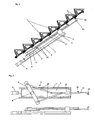
- FIG. 1 a side view of a section of an inventive escalator with a linear drive based on a crank mechanism
- the Fig. 2 is a plan view of the drive system of Fig. 1
- Fig. 3 shows the drive system of Fig. 2 in application to a drive chain of an escalator
- the Fig. 4 shows two alternative drive systems according to the invention.
- the moving transport elements 1 in the form of steps of the Fig. 1 are directly interconnected to form an escalator and thus form a closed chain of transport elements 1, which is guided over deflectors, not shown.
- the transport elements 1 or their connecting parts have sliding elements or rollers 2 with which the transport elements are guided in a guide, on a rail or the like.
- a drive system 3 acts with a drive torque, which drive system in the example of Fig. 1 a crank mechanism 4 which is mounted on a base member 5.
- This base element 5 is displaceable by a linear drive 6 parallel to the upper chain center of the chain of transport elements 1 and thus also in the direction of the drive torque on the chain in a guide 7.
- the crank mechanism 4 is, as in the plan view of Fig. 2 can be seen well, formed by a rotating shaft 8 on a driven lever 9, from the ends of each a plunger 10 emanates, which acts on a respective drive rod 11.
- the two, in the direction of the shaft 8 against each other a little offset drive rods 11 - which also applies to the tappet 10 incidentally - are guided by a guide 12 parallel to the direction of movement of the driven chain.
- At the ends of the drive rods 11 are receptacles 13 for normally on the drive direction movable pin 14, which temporarily produces the force-transmitting connection between the drive rod 11 and the chain of transport elements 1.
- the receptacles 13 could be designed as a fluidic cylinder or other drives, while the bolts 14, for example, even the piston rods such cylinders or can be connected to these.
- the bolt 14 Shortly before or when reaching the maximum extended end position of just engaging on a transport element 1 or a possible coupling piece drive rod 11, the bolt 14 is extended and accomplished with the transport element 1 and the coupling piece at least a positive connection, the base member 5 with the entire crank mechanism 4 by the linear drive 6 in the same direction, ie moved in the direction of the torque exerted by the crank mechanism 4.
- the crank mechanism 4 can at best be stopped for a short time, but it can also continue its movement.
- the other drive rod 11 is brought by extension of the bolt 14 with another transport element 1 or another coupling piece in engagement.
- the base member 5 is further moved by the linear drive 6 with the crank mechanism 4 in the direction of movement of the escalator, thus ensuring a smooth transition when changing between the two drive rods 11. Then the bolt 14 of the fully extended drive rod 11 is retracted and the connection with the chain of the transport elements 1 is released.
- the entire crank drive 4 is actively moved by the linear drive 6 or passive - by the reaction moments on the drive system - in opposite directions to the direction of movement of the coupled drive rod 11 and thus in opposite directions to the drive torque , preferably to the starting position before the active actuation of the linear drive 6.
- a drive system as explained above, the chain of transport elements 1 drive indirectly, in which the drive rods 11 are coupled via the bolt 14 with a drive chain 15, which in turn is coupled to the transport elements 1 again. From the basic sequence of the drive and the smooth changeover there is no difference between the drive rods 11 acting on the drive chain 15.
- the part of the drive system which is temporarily coupled to the chain of transport elements 1 and which comprises two oppositely movable elements alternately coupled to the chain, such as the drive rods 11, is mounted on a base element 5 displaceable by means of a linear drive 6 to ensure a smooth transition when changing the coupling.
- Fig. 4a shows a drive system with two parallel drive rods 16 which is provided at the longitudinal portion with a toothing 17 which is opposite to the receptacles 13 for the bolts 14.
- the teeth 17 of the two drive rods 16 face each other.
- one of the two drive rods 16 is designed, for example, as a piston rod of a fluidic working cylinder 18 and can exert a drive torque on it by means of the working cylinder 18 parallel to the direction of movement of the chain of transport elements 1 or its drive chain.
- a gear 19 is used, which ensures that the two drive rods 16 each move in opposite directions to each other.
- Fig. 4b shows a drive system with two mounted on the base member 5 linear actuators, such as fluidic working cylinders 20, the piston rods via a corresponding circuit alternately and in opposite directions and retracted, each one of the piston rods as a drive rod 21 with the chain of transport elements 1 or the drive chain is coupled.
- linear actuators such as fluidic working cylinders 20
- the piston rods via a corresponding circuit alternately and in opposite directions and retracted, each one of the piston rods as a drive rod 21 with the chain of transport elements 1 or the drive chain is coupled.
- linear drives in addition to the above-mentioned crank mechanism 4 and fluidic working cylinders 18, 20, electrical linear drives, worm drives or other types of linear drives can be used.
- a drive system could also be provided in which at least two of the linear drives engage a crankshaft of a drive wheel coupled to the chain at most via an intermediate gear. Also, at least two oppositely moving linear drives could alternately each attack on the deflection of the chain of transport elements 1 and the drive chain.
Landscapes
- Transmission Devices (AREA)
- Devices For Conveying Motion By Means Of Endless Flexible Members (AREA)
Description
- Die Erfindung betrifft ein Beförderungsmittel, insbesondere Rolltreppe, Rollsteig, od. dgl., mit einer Kette von separaten Transportelementen, die unter Bildung einer Kette miteinander verbunden oder mit zumindest einer Antriebskette gekoppelt sein können, einer Führung für die Transportelemente und jede allfällige Antriebskette, allenfalls Umlenkeinrichtungen an den Enden der Kette von Transportelementen und an den Enden jeder Antriebskette, und zumindest einem die Kette von Transportelementen oder jede Antriebskette bewegenden Antriebssystem, wobei für die Kette von Transportelementen oder jeder der Antriebsketten zumindest ein Linearantrieb vorgesehen ist, der in zumindest einer Arbeitsrichtung mittelbar oder unmittelbar ein Antriebsmoment auf die jeweilige Kette ausübt.
- Eine Rolltreppe oder auch ein Fahrsteig umfassen sich bewegende Transportelemente, meist aus Metall und im Fall von Rolltreppen deren Treppenstufen bildend bzw. bei einem Fahrsteig eine ebene Fläche bildend. Die Transportelemente sind untereinander verbunden, was mittelbar über beispielsweise eine Antriebskette erfolgen kann. Die Transportelemente können aber auch unmittelbar miteinander verbunden sein und somit selbst eine Kette bilden. Weiters sind Umlenkeinrichtungen an den beiden Enden der Kette, allenfalls für die Bildung von Absätzen auch dazwischen, vorgesehen.
- Herkömmliche Antriebssysteme für derartige Beförderungsmittel weisen in der Regel einen Motor mit Getriebe auf, der in Einbauräumen am oberen oder unteren Ende der Fahrtreppe montiert ist und die Antriebskette oder die Kette über ein darin eingreifendes Antriebsrad mit einem Antriebsmoment beaufschlagt. Das Antriebsrad kann zugleich auch Teil einer der Umlenkeinrichtungen sein. Derartige Antriebssysteme erfordern einen großen Einbauraum, um alle erforderliche Komponenten des Antriebs unterbringen zu können, insbesondere bei Beförderungsmitteln, die entweder große Höhendifferenzen oder große Wegstrecken überwinden müssen.
- Daneben sind z.B. aus der
DE 2 252 763 A1 , derDE 100 36 913 A1 oder derEP 1 502 892 A1 , Antriebssysteme für derartige Beförderungsmittel mit einem Linearantrieb bekannt geworden. - Es war daher die Aufgabe der vorliegenden Erfindung, ein Beförderungsmittel mit geringerem Platzbedarf anzugeben.
- Zur Lösung dieser Aufgabe ist das eingangs beschriebene Beförderungsmittel dadurch gekennzeichnet, dass für die Kette von Transportelementen oder jeder der Antriebsketten zumindest zwei sich gegensinnig bewegende Antriebsstangen vorgesehen sind, die von einem Linearantrieb angetrieben sind und von welchen immer zumindest eine Antriebsstange mittelbar oder unmittelbar ein Antriebsmoment auf die jeweilige Kette ausübt. Linearantriebe können sehr schmal ausgeführt sein, so dass bei Anordnung im Wesentlichen parallel zur Bewegungsrichtung der Transportelemente kaum zusätzlicher Bauraum verbraucht wird. Insbesondere im Bereich der Enden des Beförderungsmittels kann damit wesentlich Bauraum eingespart werden.
- Gemäß einer ersten vorteilhaften Ausführungsform der Erfindung ist vorgesehen, dass der Linearantrieb mit zwei Zahnstangen als Antriebsstangen verbunden ist, allenfalls über ein Zwischengetriebe, wobei für jede Arbeitsrichtung eine Zahnstange mit jeweils einem der gegenläufigen Kettentrümmer gekoppelt ist bzw. wobei für jede Arbeitsrichtung zumindest eine Zahnstange mit jeweils einem der gegenläufigen Kettentrümmer verbunden ist.
- Vorteilhafterweise ist dabei vorgesehen, dass in einer der Bewegungsrichtungen immer zumindest eine Antriebsstange mit der jeweiligen Kette gekoppelt ist, und wobei jede gegensinnig arbeitende Antriebsstange von der Kette abgekoppelt ist.
- Um einen ruckfreien Übergang beim Wechsel zwischen den zumindest zwei auf die Kette wirkenden Linearantrieben zu gewährleisten, gehen zwei gegensinnig arbeitende Antriebsstangen von einem gemeinsamen Basiselement aus, welches Basiselement über zumindest einen weiteren Linearantrieb parallel zum Arbeitshub der gegensinnig arbeitenden Antriebsstangen bewegt werden kann.
- Ein derartiger Antrieb wird vorteilhafterweise in einer Art eingesetzt, bei welcher gemäß einem weiteren Merkmal der Erfindung zumindest kurz vor oder bei Erreichen der Endstellung des gerade an einem Transportelement gekoppelten Antriebsstange das Basiselement mittels eines weiteren Linearantriebes in derselben Arbeitsrichtung bewegt wird, während gleichzeitig die inzwischen in Gegenrichtung ausgefahrene und entkoppelte Antriebsstange mit einem anderen Transportelement in Eingriff gebracht wird. Damit ist der ruckfreie Übergang beim Wechsel zwischen den zumindest zwei auf die Kette wirkenden Linearantrieben sichergestellt.
- Gemäß einer vorteilhaften Variante des obigen Verfahrens wird während des Arbeitshubes der gerade an einem Transportelement angreifenden Antriebsstange das Basiselement mittels des weiteren Linearantriebs aktiv oder passiv gegensinnig zu diesem-Arbeitshub bewegt.
- Eine weitere vorteilhafte Ausführungsform für ein erfindungsgemäßes Beförderungsmittel ist dadurch gekennzeichnet, dass für die Kette von Transportelementen bzw. die Antriebskette als Linearantrieb zumindest zwei Linearantriebe, die zwei sich gegensinnig bewegenden Antriebsstangen antreiben, vorgesehen sind, die an einer Kurbelwelle eines mit der Kette allenfalls über ein Zwischengetriebe gekoppelten Antriebsrades angreifen.
- Gemäß einer wieder anderen Ausführungsform der Erfindung ist das Beförderungsmittel dadurch gekennzeichnet, dass als Linearantrieb zumindest zwei Linearantriebe, die zwei sich gegensinnig bewegenden Antriebsstangen antreiben, vorgesehen sind, die abwechselnd an der Umlenkeinrichtungen der Kette von Transportelemente bzw. der Antriebskette angreifen, wobei die Umlenkeinrichtung durch ein mit der jeweiligen Kette allenfalls über ein Zwischengetriebe in Eingriff stehendes Rad gebildet ist.
- Bei dieser Ausführungsform ist vorteilhafterweise vorgesehen, dass die Antriebsstangen abwechselnd radial außerhalb von dessen Achse angreifen.
- Eine andere Variante sieht hingegen vor, dass die Umlenkeinrichtung durch ein mit der jeweiligen Kette allenfalls über ein Zwischengetriebe in Eingriff stehendes Rad gebildet ist, an welchem in Bezug die radiale Richtung schiefe Ebenen ausgebildet sind, mit welchen die Linearantriebe abwechselnd in Kontakt stehen und dabei ein Antriebsmoment auf das Rad ausüben.
- Als Linearantriebe für ein erfindungsgemäßes Beförderungsmittel können vorteilhafterweise fluidische Arbeitszylinder oder elektrische Linearantriebe vorgesehen sein. Die Erfindung ist aber nicht auf derartige Linearantriebe beschränkt, so dass allenfalls auch Schneckenantriebe oder andere Arten von Linearantrieben Verwendung finden können.
- In der nachfolgenden Beschreibung soll die Erfindung unter Bezugnahme auf die beigefügten Zeichnungen anhand einiger Ausführungsbeispiele erläutert werden.
- Dabei zeigt die
Fig. 1 eine Seitenansicht eines Ausschnittes aus einer erfindungsgemäßen Rolltreppe mit einem Linearantrieb auf Basis eines Kurbeltriebs, dieFig. 2 ist eine Draufsicht auf das Antriebssystem derFig. 1 ,Fig. 3 zeigt das Antriebssystem derFig. 2 in Anwendung auf eine Antriebskette einer Rolltreppe, und dieFig. 4 zeigt zwei alternative erfindungsgemäße Antriebssysteme. - Die sich bewegenden Transportelemente 1 in Form von Treppenstufen der
Fig. 1 sind zur Bildung einer Rolltreppe unmittelbar untereinander verbunden und bilden so eine geschlossene Kette von Transportelementen 1, die über nicht dargestellte Umlenkeinrichtungen geführt ist. Die Transportelemente 1 oder deren Verbindungsteile weisen Gleitelemente oder Rollen 2 auf, mit welchen die Transportelemente in einer Führung, auf einer Schiene od. dgl. geführt sind. Auf die Kette von Transportelementen 1 wirkt ein Antriebssystem 3 mit einem Antriebsmoment ein, welches Antriebssystem im Beispiel derFig. 1 einen Kurbeltrieb 4 umfasst, der auf einem Basiselement 5 montiert ist. Dieses Basiselement 5 ist durch einen Linearantrieb 6 parallel zum oberen Kettentrum der Kette von Transportelementen 1 und damit auch in Richtung des Antriebsmoments auf die Kette in einer Führung 7 verschiebbar. - Der Kurbeltrieb 4 wird, wie auch in der Draufsicht der
Fig. 2 gut zu erkennen ist, durch einen auf einer angetriebenen Welle 8 rotierenden Hebel 9 gebildet, von dessen Enden jeweils ein Stössel 10 ausgeht, der auf jeweils eine Antriebsstange 11 einwirkt. Die beiden, in Richtung der Welle 8 gegeneinander ein wenig versetzten Antriebsstangen 11 - was im Übrigen auch auf die Stössel 10 zutrifft - sind durch eine Führung 12 parallel zur Bewegungsrichtung des angetriebenen Kettentrums geführt. An den Enden der Antriebsstangen 11 befinden sich Aufnahmen 13 für normal auf die Antriebsrichtung bewegbare Bolzen 14, die temporär die kraftübertragende Verbindung zwischen Antriebsstange 11 und der Kette von Transportelementen 1 herstellt. Die Aufnahmen 13 könnten als fluidische Arbeitszylinder oder andere Antriebe ausgeführt sein, während die Bolzen 14 beispielsweise selbst die Kolbenstangen derartiger Arbeitszylinder oder mit diesen verbunden sein können. - Kurz vor oder bei Erreichen der maximal ausgefahrenen Endstellung der gerade an einem Transportelement 1 oder einem allfälligen Kupplungsstück angreifenden Antriebsstange 11, deren Bolzen 14 ausgefahren und mit dem Transportelement 1 bzw. dem Kupplungsstück eine zumindest kraftschlüssige Verbindung bewerkstelligt, wird das Basiselement 5 mit dem gesamten Kurbeltrieb 4 durch den Linearantrieb 6 in der selben Arbeitsrichtung, d.h. in Richtung des durch den Kurbeltrieb 4 ausgeübten Moments bewegt. Dabei kann der Kurbeltrieb 4 allenfalls auch kurzzeitig angehalten werden, kann aber auch seine Bewegung fortsetzen. Gleichzeitig wird nun die andere Antriebsstange 11 durch Ausfahren von deren Bolzen 14 mit einem anderen Transportelement 1 oder einem anderen Kupplungsstück in Eingriff gebracht. Dabei wird durch den Linearantrieb 6 das Basiselement 5 mit dem Kurbeltrieb 4 weiter in Bewegungsrichtung der Rolltreppe bewegt, um somit einen ruckfreien Übergang beim Wechsel zwischen den beiden Antriebsstangen 11 sicherzustellen. Dann wird der Bolzen 14 der komplett ausgefahrenen Antriebsstange 11 eingefahren und die Verbindung mit der Kette der Transportelemente 1 gelöst.
- Während des nun folgenden Arbeitshubes der soeben mit der Kette von Transportelementen 1 gekoppelten Antriebsstange 11 wird der gesamte Kurbeltrieb 4 entweder aktiv durch den Linearantrieb 6 oder passiv - durch die Reaktionsmomente auf das Antriebssystem - gegensinnig zur Bewegungsrichtung der gekoppelten Antriebsstange 11 und damit gegensinnig zum Antriebsmoment bewegt, vorzugsweise bis in die Ausgangsstellung vor der aktiven Betätigung des Linearantriebes 6.
- Wie in
Fig. 3 dargestellt ist, kann ein Antriebssystem wie oben erläutert die Kette von Transportelementen 1 mittelbar antreiben, in dem die Antriebsstangen 11 über deren Bolzen 14 mit einer Antriebskette 15 gekoppelt werden, die ihrerseits wieder mit den Transportelementen 1 gekoppelt ist. Vom prinzipiellen Ablauf des Antriebs und des ruckfreien Wechsels zwischen den auf die Antriebskette 15 wirkenden Antriebsstangen 11 ist kein Unterschied gegeben. - Selbstverständlich sind auch andere Antriebssysteme als jene in den
Fig. 1 bis 3 dargestellten Systemen unter Verwendung eines Kurbeltriebes 4 möglich. Zwei Beispiele für alternative Ausführungsformen sind in derFig. 4 in Draufsicht dargestellt und sollen nachfolgend erläutert werden. - Wieder ist der Teil des Antriebssystems, der temporär mit der Kette von Transportelementen 1 gekoppelt wird und der zwei gegensinnig bewegbare und abwechselnd mit der Kette gekoppelte Elemente, wie etwa die Antriebsstangen 11, umfasst, auf einem mittels eines Linearantriebs 6 verschiebbaren Basiselement 5 montiert, um einen ruckfreien Übergang beim Wechsel der Kopplung zu gewährleisten.
-
Fig. 4a zeigt ein Antriebssystem mit zwei parallel geführten Antriebsstangen 16, die an dem Längsabschnitt mit einer Verzahnung 17 versehen ist, der den Aufnahmen 13 für die Bolzen 14 entgegengesetzt ist. Die Verzahnungen 17 der beiden Antriebsstangen 16 sind einander zugewandt. Über die Verzahnung 17 hinausgehend ist eine der beiden Antriebsstangen 16 beispielsweise als Kolbenstange eines fluidischen Arbeitszylinders 18 ausgebildet und kann mittels des Arbeitszylinders 18 parallel zur Bewegungsrichtung der Kette von Transportelementen 1 oder deren Antriebskette ein Antriebsmoment auf diese ausüben. Zwischen den beiden Verzahnungen 17 ist ein Zahnrad 19 eingesetzt, das dafür sorgt, dass sich die beiden Antriebsstangen 16 jeweils gegensinnig zueinander bewegen. -
Fig. 4b hingegen zeigt ein Antriebssystem mit zwei auf dem Basiselement 5 befestigten Linearantrieben, beispielsweise fluidischen Arbeitszylindern 20, deren Kolbenstangen über eine entsprechende Schaltung abwechselnd und gegensinnig ein- und ausgefahren werden, wobei jeweils eine der Kolbenstangen als Antriebsstange 21 mit der Kette von Transportelementen 1 oder der Antriebskette gekoppelt ist. - Als Linearantriebe können neben den oben bereits genannten Kurbeltrieb 4 und fluidischen Arbeitszylindern 18, 20 auch elektrische Linearantriebe, Schneckenantriebe oder andere Arten von Linearantrieben Verwendung finden.
- Auch könnte ein Antriebssystem vorgesehen sein, bei dem zumindest zwei der Linearantriebe an einer Kurbelwelle eines mit der Kette allenfalls über ein Zwischengetriebe gekoppelten Antriebsrades angreifen. Auch könnte allenfalls von zumindest zwei sich gegensinnig bewegenden Linearantrieben abwechselnd je einer an der Umlenkeinrichtungen der Kette von Transportelementen 1 bzw. der Antriebskette angreift. Bei dieser Ausführungsform ist vorteilhafterweise vorgesehen, dass die Umlenkeinrichtung durch ein mit der jeweiligen Kette allenfalls über ein Zwischengetriebe in Eingriff stehendes Rad gebildet ist, an welchem die Linearantriebe abwechselnd radial außerhalb von dessen Achse angreifen. Alternativ dazu könnten an dem Rad in Bezug die radiale Richtung schiefe Ebenen ausgebildet sein, mit welchen die Linearantriebe abwechselnd in Kontakt stehen und dabei ein Antriebsmoment auf das Rad und damit auch auf die Kette ausüben.
Claims (12)
- Beförderungsmittel, insbesondere Rolltreppe, Rollsteig, od. dgl., mit einer Kette von separaten Transportelementen (1), die unter Bildung einer Kette miteinander verbunden oder mit zumindest einer Antriebskette (15) gekoppelt sind, einer Führung für die Transportelemente (1) und jede allfällige Antriebskette (15), allenfalls Umlenkeinrichtungen an den Enden der Kette von Transportelementen (1) und an den Enden jeder Antriebskette (15), und zumindest einem die Kette von Transportelementen (1) oder jede Antriebskette (15) bewegenden Antriebssystem, wobei für die Kette von Transportelementen (1) oder jeder der Antriebsketten (15) zumindest ein Linearantrieb vorgesehen ist, der in zumindest einer Arbeitsrichtung mittelbar oder unmittelbar ein Antriebsmoment auf die jeweilige Kette ausübt, dadurch gekennzeichnet, dass für die Kette von Transportelementen (1) oder jeder der Antriebsketten (15) zumindest zwei sich gegensinnig bewegende Antriebsstangen (11, 16, 21) vorgesehen sind, die von einem Linearantrieb oder einer angetriebenen Welle angetrieben sind und von welchen immer zumindest eine Antriebsstange (11, 16, 21) mittelbar oder unmittelbar ein Antriebsmoment auf die jeweilige Kette ausübt.
- Beförderungsmittel nach Anspruch 1, dadurch gekennzeichnet, dass der Linearantrieb mit zwei Zahnstangen als Antriebsstangen (16) verbunden ist, allenfalls über ein Zwischengetriebe, wobei für jede Arbeitsrichtung eine Zahnstange mit jeweils einem der gegenläufigen Kettentrümer gekoppelt ist bzw. wobei für jede Arbeitsrichtung zumindest eine Zahnstange mit jeweils einem der gegenläufigen Kettentrümer verbunden ist.
- Beförderungsmittel nach Anspruch 1, dadurch gekennzeichnet, dass für die Kette von Transportelementen (1) oder jeder der Antriebsketten (15) zumindest zwei sich gegensinnig bewegende Linearantriebe als Linearantriebe vorgesehen sind, die die zwei sich gegensinnig bewegenden Antriebsstangen (16, 21) antreiben.
- Beförderungsmittel nach Anspruch 1, dadurch gekennzeichnet, dass als Linearantrieb ein Kurbeltrieb (4) mit zwei Stößeln (10), an denen jeweils eine in einer Führung (12) geführte Antriebsstange (11) befestigt ist, vorgesehen ist.
- Beförderungsmittel nach einem der Ansprüche 1 bis 4, dadurch gekennzeichnet, dass in einer der Bewegungsrichtungen immer zumindest eine Antriebsstange (11, 16, 21) mit der jeweiligen Kette gekoppelt ist, wobei die gegensinnig arbeitende Antriebsstange (11, 16, 21) von der Kette abgekoppelt ist.
- Beförderungsmittel nach Anspruch 1, dadurch gekennzeichnet, dass die zwei gegensinnig arbeitenden Antriebsstangen (11, 16, 21) von einem gemeinsamen Basiselement (5) ausgehen, welches Basiselement (5) über zumindest einen weiteren Linearantrieb (6) parallel zum Arbeitshub der gegensinnig arbeitenden Antriebsstangen (11, 16, 21) bewegt werden kann.
- Verfahren zum Betreiben eines Beförderungsmittels nach Anspruch 6, dadurch gekennzeichnet, dass zumindest kurz vor oder bei Erreichen der Endstellung der gerade mit der Kette von Transportelementen (1) oder der Antriebsketten (15) gekoppelten Antriebsstange (11, 16, 21) das Basiselement (5) mittels eines weiteren Linearantriebes (6) in der selben Arbeitsrichtung bewegt wird, während gleichzeitig die inzwischen in Gegenrichtung ausgefahrene und entkoppelte Antriebsstange (11, 16, 21) mit der Kette von Transportelementen (1) oder der Antriebsketten (15) in Eingriff gebracht wird.
- Verfahren nach Anspruch 7, dadurch gekennzeichnet, dass während des Arbeitshubes der gerade an der Kette von Transportelementen (1) oder der Antriebsketten (15) angreifenden Antriebsstange (11, 16, 21) das Basiselement (5) aktiv mittels des weiteren Linearantriebs (6) oder passiv gegensinnig zu diesem Arbeitshub bewegt wird.
- Beförderungsmittel nach Anspruch 1, dadurch gekennzeichnet, dass für die Kette von Transportelementen (1) oder die Antriebskette (15) als Linearantrieb zumindest zwei Linearantriebe, die zwei sich gegensinnig bewegenden Antriebsstangen (11, 16, 21) antreiben, vorgesehen sind, die an einer Kurbelwelle eines mit der Kette allenfalls über ein Zwischengetriebe gekoppelten Antriebsrades angreifen.
- Beförderungsmittel nach Anspruch 1, dadurch gekennzeichnet, dass als Linearantrieb zumindest zwei Linearantriebe, die zwei sich gegensinnig bewegenden Antriebsstangen (11, 16, 21) antreiben, vorgesehen sind, die abwechselnd an einer Umlenkeinrichtung der Kette von Transportelemente (1) bzw. der Antriebskette (15) angreifen, wobei die Umlenkeinrichtung durch ein mit der jeweiligen Kette allenfalls über ein Zwischengetriebe in Eingriff stehendes Rad gebildet ist.
- Beförderungsmittel nach einem der Ansprüche 1 bis 10, dadurch gekennzeichnet, dass als Linearantriebe fluidische Arbeitszylinder (18, 20) mit einem Arbeitsfluid vorgesehen sind.
- Beförderungsmittel nach einem der Ansprüche 1 bis 10, dadurch gekennzeichnet, dass elektrische Linearantriebe vorgesehen sind.
Applications Claiming Priority (2)
| Application Number | Priority Date | Filing Date | Title |
|---|---|---|---|
| AT12492010A AT510182A1 (de) | 2010-07-26 | 2010-07-26 | Beförderungsmittel, insbesondere rolltreppe, rollsteig, oder dergleichen |
| PCT/EP2011/062139 WO2012013520A1 (de) | 2010-07-26 | 2011-07-15 | Beförderungsmittel, insbesondere rolltreppe, rollsteig, oder dergleichen |
Publications (2)
| Publication Number | Publication Date |
|---|---|
| EP2598427A1 EP2598427A1 (de) | 2013-06-05 |
| EP2598427B1 true EP2598427B1 (de) | 2015-04-01 |
Family
ID=44629137
Family Applications (1)
| Application Number | Title | Priority Date | Filing Date |
|---|---|---|---|
| EP11736328.3A Not-in-force EP2598427B1 (de) | 2010-07-26 | 2011-07-15 | Beförderungsmittel, insbesondere rolltreppe, rollsteig, oder dergleichen |
Country Status (3)
| Country | Link |
|---|---|
| EP (1) | EP2598427B1 (de) |
| AT (1) | AT510182A1 (de) |
| WO (1) | WO2012013520A1 (de) |
Family Cites Families (8)
| Publication number | Priority date | Publication date | Assignee | Title |
|---|---|---|---|---|
| DE1456375A1 (de) * | 1966-04-14 | 1968-12-12 | Orenstein & Koppel Ag | Antrieb fuer Rolltreppen |
| DE2252763A1 (de) * | 1972-10-27 | 1974-05-02 | Pohlig Heckel Bleichert | Foerdereinrichtung wie fahrtreppe, fahrsteig od. dgl. |
| JPH0784317B2 (ja) * | 1990-03-19 | 1995-09-13 | 株式会社日立製作所 | 乗客コンベア |
| DE10036913B4 (de) * | 2000-07-28 | 2005-05-04 | Otis Elevator Co., Farmington | Fahrtreppen- oder Fahrsteig-Antrieb |
| EP1502892A1 (de) * | 2003-07-31 | 2005-02-02 | Inventio Ag | Antriebseinrichtung für Fahrtreppenstufe |
| ZA200405180B (en) * | 2003-07-31 | 2005-03-11 | Inventio Ag | Drive equipment for escalator step or moving walkway plate. |
| ES2289955B1 (es) * | 2006-12-29 | 2009-05-05 | Thyssenkrupp Norte, S.A. | Sistema de transporte para desplazamiento de pasajeros/mercancias. |
| ES2446070T3 (es) * | 2007-11-28 | 2014-03-06 | Thyssenkrupp Elevator (Es/Pbb) Ltd. | Sistema de transporte para desplazamiento de pasajeros/mercancías |
-
2010
- 2010-07-26 AT AT12492010A patent/AT510182A1/de not_active Application Discontinuation
-
2011
- 2011-07-15 WO PCT/EP2011/062139 patent/WO2012013520A1/de not_active Ceased
- 2011-07-15 EP EP11736328.3A patent/EP2598427B1/de not_active Not-in-force
Also Published As
| Publication number | Publication date |
|---|---|
| AT510182A1 (de) | 2012-02-15 |
| WO2012013520A1 (de) | 2012-02-02 |
| EP2598427A1 (de) | 2013-06-05 |
Similar Documents
| Publication | Publication Date | Title |
|---|---|---|
| DE69703635T2 (de) | Angetriebene Verriegelungsvorrichtung für Fahrzeuge mit verbesserten Mitteln zur Begrenzung der Bewegung eines Riegels | |
| EP2598428B1 (de) | Vorrichtung zur aufnahme von lasten | |
| DE10230024C1 (de) | Schließmechanismus für eine Spritzgießmaschine | |
| EP2732177B1 (de) | Formschlusskupplungsbetätigungsvorrichtung eines kraftfahrzeuggetriebes | |
| EP2585396B1 (de) | Klemm- und zugvorrichtung | |
| DE102011116654A1 (de) | Vorrichtung zum Stanznieten und Durchsetzfügen unter beengten Platzverhältnissen | |
| DE102010060759A1 (de) | Schubboden-Fördereinrichtung | |
| DE10106193B4 (de) | Hubeinheit | |
| EP3966409B1 (de) | Vorrichtung zum abstellen von gegenständen mit horizontal orientiertem antrieb | |
| EP3405698B1 (de) | Aktuator mit hohlschnecke | |
| AT511233B1 (de) | Beförderungsmittel, mit zumindest einem transportelement und einem antriebssystem für das transportelement | |
| EP2598427A1 (de) | Beförderungsmittel, insbesondere rolltreppe, rollsteig, oder dergleichen | |
| DE102008018655A1 (de) | Trommelbremse | |
| DE202008007902U1 (de) | Verriegelungsvorrichtung mit Rotorbetätigung nach unten | |
| DE3623247A1 (de) | Spannvorrichtung fuer die antriebsfeder eines energiespeichers fuer elektrische schalter | |
| AT520004B1 (de) | Schließeinheit einer Spritzgießmaschine | |
| DE19614623C2 (de) | Gabelzinke für Hubstapelgeräte | |
| WO2012089760A1 (de) | Beförderungsmittel für lasten oder personen | |
| EP1512648B1 (de) | Vorrichtung zur Übergabe von Stückgut | |
| EP3141660B1 (de) | Kuppelvorrichtung zur verbindung zweier brückenelemente | |
| DE10112983C1 (de) | Antriebsvorrichtung für ein Presswerkzeug oder dergleichen | |
| EP2874793B1 (de) | Schliesseinheit für eine kunststoffspritzgiessmaschine | |
| DE102006046862B3 (de) | Verfahren und Stellkrafterzeuger zur Bedienung von Montageplattformen | |
| DE102007044162A1 (de) | Hubkolbenmaschine | |
| EP1142657A2 (de) | Auswerfereinrichtung, Mehrstufenpresse und Verfahren zum Verstellen der Hubhöhe einer Auswerfereinrichtung |
Legal Events
| Date | Code | Title | Description |
|---|---|---|---|
| PUAI | Public reference made under article 153(3) epc to a published international application that has entered the european phase |
Free format text: ORIGINAL CODE: 0009012 |
|
| 17P | Request for examination filed |
Effective date: 20130213 |
|
| AK | Designated contracting states |
Kind code of ref document: A1 Designated state(s): AL AT BE BG CH CY CZ DE DK EE ES FI FR GB GR HR HU IE IS IT LI LT LU LV MC MK MT NL NO PL PT RO RS SE SI SK SM TR |
|
| DAX | Request for extension of the european patent (deleted) | ||
| GRAP | Despatch of communication of intention to grant a patent |
Free format text: ORIGINAL CODE: EPIDOSNIGR1 |
|
| INTG | Intention to grant announced |
Effective date: 20141029 |
|
| GRAS | Grant fee paid |
Free format text: ORIGINAL CODE: EPIDOSNIGR3 |
|
| GRAA | (expected) grant |
Free format text: ORIGINAL CODE: 0009210 |
|
| AK | Designated contracting states |
Kind code of ref document: B1 Designated state(s): AL AT BE BG CH CY CZ DE DK EE ES FI FR GB GR HR HU IE IS IT LI LT LU LV MC MK MT NL NO PL PT RO RS SE SI SK SM TR |
|
| REG | Reference to a national code |
Ref country code: GB Ref legal event code: FG4D Free format text: NOT ENGLISH |
|
| REG | Reference to a national code |
Ref country code: CH Ref legal event code: EP |
|
| REG | Reference to a national code |
Ref country code: IE Ref legal event code: FG4D Free format text: LANGUAGE OF EP DOCUMENT: GERMAN |
|
| REG | Reference to a national code |
Ref country code: DE Ref legal event code: R096 Ref document number: 502011006459 Country of ref document: DE Effective date: 20150507 |
|
| REG | Reference to a national code |
Ref country code: AT Ref legal event code: REF Ref document number: 718955 Country of ref document: AT Kind code of ref document: T Effective date: 20150515 |
|
| REG | Reference to a national code |
Ref country code: CH Ref legal event code: NV Representative=s name: ISLER AND PEDRAZZINI AG, CH |
|
| REG | Reference to a national code |
Ref country code: NL Ref legal event code: VDEP Effective date: 20150401 |
|
| REG | Reference to a national code |
Ref country code: LT Ref legal event code: MG4D |
|
| PG25 | Lapsed in a contracting state [announced via postgrant information from national office to epo] |
Ref country code: NL Free format text: LAPSE BECAUSE OF FAILURE TO SUBMIT A TRANSLATION OF THE DESCRIPTION OR TO PAY THE FEE WITHIN THE PRESCRIBED TIME-LIMIT Effective date: 20150401 |
|
| PG25 | Lapsed in a contracting state [announced via postgrant information from national office to epo] |
Ref country code: NO Free format text: LAPSE BECAUSE OF FAILURE TO SUBMIT A TRANSLATION OF THE DESCRIPTION OR TO PAY THE FEE WITHIN THE PRESCRIBED TIME-LIMIT Effective date: 20150701 Ref country code: LT Free format text: LAPSE BECAUSE OF FAILURE TO SUBMIT A TRANSLATION OF THE DESCRIPTION OR TO PAY THE FEE WITHIN THE PRESCRIBED TIME-LIMIT Effective date: 20150401 Ref country code: FI Free format text: LAPSE BECAUSE OF FAILURE TO SUBMIT A TRANSLATION OF THE DESCRIPTION OR TO PAY THE FEE WITHIN THE PRESCRIBED TIME-LIMIT Effective date: 20150401 Ref country code: ES Free format text: LAPSE BECAUSE OF FAILURE TO SUBMIT A TRANSLATION OF THE DESCRIPTION OR TO PAY THE FEE WITHIN THE PRESCRIBED TIME-LIMIT Effective date: 20150401 Ref country code: HR Free format text: LAPSE BECAUSE OF FAILURE TO SUBMIT A TRANSLATION OF THE DESCRIPTION OR TO PAY THE FEE WITHIN THE PRESCRIBED TIME-LIMIT Effective date: 20150401 Ref country code: PT Free format text: LAPSE BECAUSE OF FAILURE TO SUBMIT A TRANSLATION OF THE DESCRIPTION OR TO PAY THE FEE WITHIN THE PRESCRIBED TIME-LIMIT Effective date: 20150803 Ref country code: CZ Free format text: LAPSE BECAUSE OF FAILURE TO SUBMIT A TRANSLATION OF THE DESCRIPTION OR TO PAY THE FEE WITHIN THE PRESCRIBED TIME-LIMIT Effective date: 20150401 |
|
| PG25 | Lapsed in a contracting state [announced via postgrant information from national office to epo] |
Ref country code: IS Free format text: LAPSE BECAUSE OF FAILURE TO SUBMIT A TRANSLATION OF THE DESCRIPTION OR TO PAY THE FEE WITHIN THE PRESCRIBED TIME-LIMIT Effective date: 20150801 Ref country code: LV Free format text: LAPSE BECAUSE OF FAILURE TO SUBMIT A TRANSLATION OF THE DESCRIPTION OR TO PAY THE FEE WITHIN THE PRESCRIBED TIME-LIMIT Effective date: 20150401 Ref country code: GR Free format text: LAPSE BECAUSE OF FAILURE TO SUBMIT A TRANSLATION OF THE DESCRIPTION OR TO PAY THE FEE WITHIN THE PRESCRIBED TIME-LIMIT Effective date: 20150702 Ref country code: RS Free format text: LAPSE BECAUSE OF FAILURE TO SUBMIT A TRANSLATION OF THE DESCRIPTION OR TO PAY THE FEE WITHIN THE PRESCRIBED TIME-LIMIT Effective date: 20150401 |
|
| REG | Reference to a national code |
Ref country code: DE Ref legal event code: R097 Ref document number: 502011006459 Country of ref document: DE |
|
| PG25 | Lapsed in a contracting state [announced via postgrant information from national office to epo] |
Ref country code: DK Free format text: LAPSE BECAUSE OF FAILURE TO SUBMIT A TRANSLATION OF THE DESCRIPTION OR TO PAY THE FEE WITHIN THE PRESCRIBED TIME-LIMIT Effective date: 20150401 Ref country code: EE Free format text: LAPSE BECAUSE OF FAILURE TO SUBMIT A TRANSLATION OF THE DESCRIPTION OR TO PAY THE FEE WITHIN THE PRESCRIBED TIME-LIMIT Effective date: 20150401 |
|
| PLBE | No opposition filed within time limit |
Free format text: ORIGINAL CODE: 0009261 |
|
| STAA | Information on the status of an ep patent application or granted ep patent |
Free format text: STATUS: NO OPPOSITION FILED WITHIN TIME LIMIT |
|
| PG25 | Lapsed in a contracting state [announced via postgrant information from national office to epo] |
Ref country code: SK Free format text: LAPSE BECAUSE OF FAILURE TO SUBMIT A TRANSLATION OF THE DESCRIPTION OR TO PAY THE FEE WITHIN THE PRESCRIBED TIME-LIMIT Effective date: 20150401 Ref country code: PL Free format text: LAPSE BECAUSE OF FAILURE TO SUBMIT A TRANSLATION OF THE DESCRIPTION OR TO PAY THE FEE WITHIN THE PRESCRIBED TIME-LIMIT Effective date: 20150401 Ref country code: RO Free format text: LAPSE BECAUSE OF NON-PAYMENT OF DUE FEES Effective date: 20150401 Ref country code: MC Free format text: LAPSE BECAUSE OF FAILURE TO SUBMIT A TRANSLATION OF THE DESCRIPTION OR TO PAY THE FEE WITHIN THE PRESCRIBED TIME-LIMIT Effective date: 20150401 |
|
| 26N | No opposition filed |
Effective date: 20160105 |
|
| GBPC | Gb: european patent ceased through non-payment of renewal fee |
Effective date: 20150715 |
|
| PG25 | Lapsed in a contracting state [announced via postgrant information from national office to epo] |
Ref country code: LU Free format text: LAPSE BECAUSE OF FAILURE TO SUBMIT A TRANSLATION OF THE DESCRIPTION OR TO PAY THE FEE WITHIN THE PRESCRIBED TIME-LIMIT Effective date: 20150715 |
|
| REG | Reference to a national code |
Ref country code: IE Ref legal event code: MM4A |
|
| PG25 | Lapsed in a contracting state [announced via postgrant information from national office to epo] |
Ref country code: GB Free format text: LAPSE BECAUSE OF NON-PAYMENT OF DUE FEES Effective date: 20150715 Ref country code: IT Free format text: LAPSE BECAUSE OF FAILURE TO SUBMIT A TRANSLATION OF THE DESCRIPTION OR TO PAY THE FEE WITHIN THE PRESCRIBED TIME-LIMIT Effective date: 20150401 |
|
| REG | Reference to a national code |
Ref country code: FR Ref legal event code: ST Effective date: 20160331 |
|
| PG25 | Lapsed in a contracting state [announced via postgrant information from national office to epo] |
Ref country code: SI Free format text: LAPSE BECAUSE OF FAILURE TO SUBMIT A TRANSLATION OF THE DESCRIPTION OR TO PAY THE FEE WITHIN THE PRESCRIBED TIME-LIMIT Effective date: 20150401 Ref country code: FR Free format text: LAPSE BECAUSE OF NON-PAYMENT OF DUE FEES Effective date: 20150731 |
|
| PG25 | Lapsed in a contracting state [announced via postgrant information from national office to epo] |
Ref country code: IE Free format text: LAPSE BECAUSE OF NON-PAYMENT OF DUE FEES Effective date: 20150715 |
|
| PGFP | Annual fee paid to national office [announced via postgrant information from national office to epo] |
Ref country code: CH Payment date: 20160721 Year of fee payment: 6 |
|
| PG25 | Lapsed in a contracting state [announced via postgrant information from national office to epo] |
Ref country code: MT Free format text: LAPSE BECAUSE OF FAILURE TO SUBMIT A TRANSLATION OF THE DESCRIPTION OR TO PAY THE FEE WITHIN THE PRESCRIBED TIME-LIMIT Effective date: 20150401 |
|
| PG25 | Lapsed in a contracting state [announced via postgrant information from national office to epo] |
Ref country code: HU Free format text: LAPSE BECAUSE OF FAILURE TO SUBMIT A TRANSLATION OF THE DESCRIPTION OR TO PAY THE FEE WITHIN THE PRESCRIBED TIME-LIMIT; INVALID AB INITIO Effective date: 20110715 Ref country code: BG Free format text: LAPSE BECAUSE OF FAILURE TO SUBMIT A TRANSLATION OF THE DESCRIPTION OR TO PAY THE FEE WITHIN THE PRESCRIBED TIME-LIMIT Effective date: 20150401 Ref country code: SM Free format text: LAPSE BECAUSE OF FAILURE TO SUBMIT A TRANSLATION OF THE DESCRIPTION OR TO PAY THE FEE WITHIN THE PRESCRIBED TIME-LIMIT Effective date: 20150401 |
|
| PG25 | Lapsed in a contracting state [announced via postgrant information from national office to epo] |
Ref country code: CY Free format text: LAPSE BECAUSE OF FAILURE TO SUBMIT A TRANSLATION OF THE DESCRIPTION OR TO PAY THE FEE WITHIN THE PRESCRIBED TIME-LIMIT Effective date: 20150401 Ref country code: SE Free format text: LAPSE BECAUSE OF FAILURE TO SUBMIT A TRANSLATION OF THE DESCRIPTION OR TO PAY THE FEE WITHIN THE PRESCRIBED TIME-LIMIT Effective date: 20150401 |
|
| PG25 | Lapsed in a contracting state [announced via postgrant information from national office to epo] |
Ref country code: BE Free format text: LAPSE BECAUSE OF NON-PAYMENT OF DUE FEES Effective date: 20150731 |
|
| PGFP | Annual fee paid to national office [announced via postgrant information from national office to epo] |
Ref country code: AT Payment date: 20170713 Year of fee payment: 7 |
|
| REG | Reference to a national code |
Ref country code: CH Ref legal event code: PL |
|
| PG25 | Lapsed in a contracting state [announced via postgrant information from national office to epo] |
Ref country code: LI Free format text: LAPSE BECAUSE OF NON-PAYMENT OF DUE FEES Effective date: 20170731 Ref country code: CH Free format text: LAPSE BECAUSE OF NON-PAYMENT OF DUE FEES Effective date: 20170731 |
|
| PG25 | Lapsed in a contracting state [announced via postgrant information from national office to epo] |
Ref country code: MK Free format text: LAPSE BECAUSE OF FAILURE TO SUBMIT A TRANSLATION OF THE DESCRIPTION OR TO PAY THE FEE WITHIN THE PRESCRIBED TIME-LIMIT Effective date: 20150401 Ref country code: TR Free format text: LAPSE BECAUSE OF FAILURE TO SUBMIT A TRANSLATION OF THE DESCRIPTION OR TO PAY THE FEE WITHIN THE PRESCRIBED TIME-LIMIT Effective date: 20150401 |
|
| PG25 | Lapsed in a contracting state [announced via postgrant information from national office to epo] |
Ref country code: AL Free format text: LAPSE BECAUSE OF FAILURE TO SUBMIT A TRANSLATION OF THE DESCRIPTION OR TO PAY THE FEE WITHIN THE PRESCRIBED TIME-LIMIT Effective date: 20150401 |
|
| PGFP | Annual fee paid to national office [announced via postgrant information from national office to epo] |
Ref country code: DE Payment date: 20180731 Year of fee payment: 8 |
|
| REG | Reference to a national code |
Ref country code: AT Ref legal event code: MM01 Ref document number: 718955 Country of ref document: AT Kind code of ref document: T Effective date: 20180715 |
|
| PG25 | Lapsed in a contracting state [announced via postgrant information from national office to epo] |
Ref country code: AT Free format text: LAPSE BECAUSE OF NON-PAYMENT OF DUE FEES Effective date: 20180715 |
|
| REG | Reference to a national code |
Ref country code: DE Ref legal event code: R119 Ref document number: 502011006459 Country of ref document: DE |
|
| PG25 | Lapsed in a contracting state [announced via postgrant information from national office to epo] |
Ref country code: DE Free format text: LAPSE BECAUSE OF NON-PAYMENT OF DUE FEES Effective date: 20200201 |