EP2597328A2 - Kupplungsanordnung für einen Fahrzeugantriebsstrang - Google Patents
Kupplungsanordnung für einen Fahrzeugantriebsstrang Download PDFInfo
- Publication number
- EP2597328A2 EP2597328A2 EP20120193590 EP12193590A EP2597328A2 EP 2597328 A2 EP2597328 A2 EP 2597328A2 EP 20120193590 EP20120193590 EP 20120193590 EP 12193590 A EP12193590 A EP 12193590A EP 2597328 A2 EP2597328 A2 EP 2597328A2
- Authority
- EP
- European Patent Office
- Prior art keywords
- clutch
- coupling
- actuator
- cavity
- housing
- Prior art date
- Legal status (The legal status is an assumption and is not a legal conclusion. Google has not performed a legal analysis and makes no representation as to the accuracy of the status listed.)
- Granted
Links
- 230000008878 coupling Effects 0.000 title claims abstract description 55
- 238000010168 coupling process Methods 0.000 title claims abstract description 55
- 238000005859 coupling reaction Methods 0.000 title claims abstract description 55
- 239000012530 fluid Substances 0.000 claims description 25
- 230000005540 biological transmission Effects 0.000 claims description 22
- 230000009977 dual effect Effects 0.000 claims description 8
- 230000000712 assembly Effects 0.000 description 6
- 238000000429 assembly Methods 0.000 description 6
- 230000000903 blocking effect Effects 0.000 description 5
- 238000010276 construction Methods 0.000 description 5
- 238000007789 sealing Methods 0.000 description 5
- 230000008901 benefit Effects 0.000 description 4
- 238000002485 combustion reaction Methods 0.000 description 4
- 230000009467 reduction Effects 0.000 description 4
- 230000003068 static effect Effects 0.000 description 4
- 238000012546 transfer Methods 0.000 description 4
- 238000013461 design Methods 0.000 description 2
- 238000009434 installation Methods 0.000 description 2
- 230000010354 integration Effects 0.000 description 2
- 238000004519 manufacturing process Methods 0.000 description 2
- 230000004913 activation Effects 0.000 description 1
- 230000004888 barrier function Effects 0.000 description 1
- 238000011161 development Methods 0.000 description 1
- 238000002955 isolation Methods 0.000 description 1
- 230000004048 modification Effects 0.000 description 1
- 238000012986 modification Methods 0.000 description 1
- 230000001105 regulatory effect Effects 0.000 description 1
- 239000007787 solid Substances 0.000 description 1
- 238000013519 translation Methods 0.000 description 1
Images

Classifications
-
- F—MECHANICAL ENGINEERING; LIGHTING; HEATING; WEAPONS; BLASTING
- F16—ENGINEERING ELEMENTS AND UNITS; GENERAL MEASURES FOR PRODUCING AND MAINTAINING EFFECTIVE FUNCTIONING OF MACHINES OR INSTALLATIONS; THERMAL INSULATION IN GENERAL
- F16H—GEARING
- F16H48/00—Differential gearings
- F16H48/20—Arrangements for suppressing or influencing the differential action, e.g. locking devices
- F16H48/22—Arrangements for suppressing or influencing the differential action, e.g. locking devices using friction clutches or brakes
-
- F—MECHANICAL ENGINEERING; LIGHTING; HEATING; WEAPONS; BLASTING
- F16—ENGINEERING ELEMENTS AND UNITS; GENERAL MEASURES FOR PRODUCING AND MAINTAINING EFFECTIVE FUNCTIONING OF MACHINES OR INSTALLATIONS; THERMAL INSULATION IN GENERAL
- F16D—COUPLINGS FOR TRANSMITTING ROTATION; CLUTCHES; BRAKES
- F16D21/00—Systems comprising a plurality of actuated clutches
-
- F—MECHANICAL ENGINEERING; LIGHTING; HEATING; WEAPONS; BLASTING
- F16—ENGINEERING ELEMENTS AND UNITS; GENERAL MEASURES FOR PRODUCING AND MAINTAINING EFFECTIVE FUNCTIONING OF MACHINES OR INSTALLATIONS; THERMAL INSULATION IN GENERAL
- F16D—COUPLINGS FOR TRANSMITTING ROTATION; CLUTCHES; BRAKES
- F16D25/00—Fluid-actuated clutches
- F16D25/06—Fluid-actuated clutches in which the fluid actuates a piston incorporated in, i.e. rotating with the clutch
- F16D25/062—Fluid-actuated clutches in which the fluid actuates a piston incorporated in, i.e. rotating with the clutch the clutch having friction surfaces
- F16D25/063—Fluid-actuated clutches in which the fluid actuates a piston incorporated in, i.e. rotating with the clutch the clutch having friction surfaces with clutch members exclusively moving axially
- F16D25/0635—Fluid-actuated clutches in which the fluid actuates a piston incorporated in, i.e. rotating with the clutch the clutch having friction surfaces with clutch members exclusively moving axially with flat friction surfaces, e.g. discs
- F16D25/0638—Fluid-actuated clutches in which the fluid actuates a piston incorporated in, i.e. rotating with the clutch the clutch having friction surfaces with clutch members exclusively moving axially with flat friction surfaces, e.g. discs with more than two discs, e.g. multiple lamellae
-
- F—MECHANICAL ENGINEERING; LIGHTING; HEATING; WEAPONS; BLASTING
- F16—ENGINEERING ELEMENTS AND UNITS; GENERAL MEASURES FOR PRODUCING AND MAINTAINING EFFECTIVE FUNCTIONING OF MACHINES OR INSTALLATIONS; THERMAL INSULATION IN GENERAL
- F16D—COUPLINGS FOR TRANSMITTING ROTATION; CLUTCHES; BRAKES
- F16D25/00—Fluid-actuated clutches
- F16D25/08—Fluid-actuated clutches with fluid-actuated member not rotating with a clutching member
-
- F—MECHANICAL ENGINEERING; LIGHTING; HEATING; WEAPONS; BLASTING
- F16—ENGINEERING ELEMENTS AND UNITS; GENERAL MEASURES FOR PRODUCING AND MAINTAINING EFFECTIVE FUNCTIONING OF MACHINES OR INSTALLATIONS; THERMAL INSULATION IN GENERAL
- F16D—COUPLINGS FOR TRANSMITTING ROTATION; CLUTCHES; BRAKES
- F16D25/00—Fluid-actuated clutches
- F16D25/06—Fluid-actuated clutches in which the fluid actuates a piston incorporated in, i.e. rotating with the clutch
Definitions
- the present invention relates to a clutch assembly, in particular for a vehicle drive train, with a rotary member, which is rotatably mounted on a housing about a longitudinal axis and defines a cavity, a coupling having a first coupling member and a second coupling member coupled thereto and in the Cavity is arranged, wherein the first coupling member or the second coupling member is coupled to the rotary member, and having a fluidic actuator assembly having a first and a second actuator member which are movable for actuating the clutch relative to each other.
- Such clutch assemblies are used for example in vehicle drive trains as starting clutches, which are arranged between an internal combustion engine and a speed-reduction gear. Furthermore, find such coupling arrangements use as a lock-up clutches. These may be, for example, so-called “hill-on clutches", which connect a second driven axle with a cardan shaft or the like to set up a four-wheel drive as needed.
- Such locking clutches can also be used as cross-locking clutches use, for example, a right and a left drive shaft of a driven axle are connected to each other, to set up in this way a transverse locking function.
- such locking clutches can be used in twin-clutch assemblies that connect an output of a drive unit without mechanical differential with a left or a right drive shaft of a driven axle.
- cross-locking clutches In the transverse lock-up clutches, a speed compensation due to a mechanical differential of a driven axle can be inhibited.
- the advantage of such cross-locking clutches is that they can also be used in vehicles driven by only one axle, whereby properties can be achieved which are close to those of a sporty all-wheel drive.
- Such cross-locking clutches can for example be flanged as additional clutches from the outside to a transmission housing and rotatably connected via a spline with a differential carrier.
- the hydraulic pressure is transferred from a housing in which there is a pressure source to the rotating locking clutch and the pressure piston integrated therein via a so-called rotary feedthrough.
- the clutch assembly may be formed as a self-contained system that can be integrated into a transmission using clearly defined existing interfaces.
- the required rotary feedthrough is technically very demanding and usually associated with a relatively high leakage rate. This makes it difficult to use a common source of pressure when integrated with an existing transmission.
- the compensation occurring centrifugal forces in the plunger is structurally complex and therefore expensive.
- ETM ball ramp systems
- an electric motor drives a ball ramp via a strong gear ratio. Due to the pitch in the ball track an axial force is generated, which compresses a disk set and thereby enables the torque transmission.
- the pilot clutch may decelerate a portion of the ball ramp, causing a relative speed in the ball ramp.
- the ball ramp can apply force to the actual clutch pack and generate the blocking effect or close the clutch.
- a clutch assembly which can be well integrated in a vehicle drive train and / or which can be formed as a closed system or module.
- the friction clutch can be formed as a self-contained module, so that there is an improved integrability in vehicle drive trains.
- the first actuator member is supported within the cavity via a first thrust bearing on the rotary member.
- At least the first actuator member is preferably axially displaceable relative to the housing fixable.
- the first actuator member in this case has a longitudinal portion which extends from the housing into the cavity, and a radial portion, by means of which the first actuator member can be supported within the cavity via the first thrust bearing on the rotary member.
- the second actuator member can also be secured against rotation on the housing and extends into the cavity from outside the rotary member.
- the actuator can be easily moved constructively into the cavity, so that there is a closed module for the clutch assembly.
- the second actuator member is preferably also axially displaceably mounted with respect to the housing (for example via a spline or the like).
- the second actuator member engages via a second thrust bearing on the friction clutch.
- the second actuator member preferably has a longitudinal portion which extends from the housing into the cavity, and a radial portion which engages via the second thrust bearing on the friction clutch.
- a pressure chamber is formed within the cavity between the first and the second actuator member, which is connectable via a fluid channel with a housing-fixed fluid supply device, wherein the fluid channel in one of the actuator members and / or is formed between the first actuator member and the second actuator member.
- the fluid from the housing-fixed fluid supply device (which has, for example via pressure control devices, etc.) are passed into the pressure chamber.
- the actuator assembly can be realized without rotary feedthrough.
- the fluid can be supplied via the housing in the interior of the cavity, wherein a seal of the first and / or the second actuator member relative to the housing can be done easily via ring seals such as O-ring seals or the like.
- a seal is provided for sealing the pressure chamber within the cavity between the first and the second actuator member, which may also be easily formed as an O-ring seal or the like.
- one of the actuator members at the free end of the radial portion has a further longitudinal portion which engages over the radial portion of the other actuator member, wherein in this area the seal may be provided.
- the cavity can be sealed off from the environment and / or with respect to the fluidic actuator arrangement.
- the rotary member forming the cavity may constitute the "outer shell" of the closed clutch assembly module within which a pressure space of the actuator assembly is formed.
- the cavity can also be sealed off from the fluidic actuator arrangement, it is also possible to actuate a dry friction clutch by means of the fluidic actuator arrangement, wherein the clutch is preferably designed as a wet-running multi-disc clutch.
- the first coupling member is coupled via a set of wheels with the rotary member.
- the Radsatzan Aunt can establish a translation between the rotary member and the first coupling member. Further, it is possible to form the wheelset assembly as a mechanical differential, such that the clutch assembly may be as a transverse or longitudinal lock of a torque distributing differential of a drive train.
- a lockable differential with a housing and with a coupling arrangement of the type according to the invention, wherein the first coupling member is coupled via a Radsatzan für With the rotary member, the Radsatzan whatsoever a Umlaufradsatzan für With a first Radsatzglied, a second Radsatzglied and with a third Radsatzglied, wherein the first Radsatzglied is connected to the one input of the differential forming rotary member, wherein the second and the third Radsatzglied form outputs of the differential and wherein the first coupling member is connected to the second Radsatzglied, and wherein the second coupling member is connected to the third Radsatzglied.
- Such a lockable differential can be provided in a simple manner in the installation space, which is provided for example in front-transverse transmissions for a differential anyway.
- the drive of the lockable differential can be done by the rotary member, which in the present case forms a kind of differential carrier, is connected to a gear which can be connected to the output of a drive unit (for example, internal combustion engine and speed reduction gearbox).
- a drive unit for example, internal combustion engine and speed reduction gearbox
- the clutch assembly is formed in the manner of a dog clutch.
- the clutch is a friction clutch, in particular a wet-running multi-plate clutch.
- the second gear member or the second Radsatzglied forms an additional friction pair with the rotary member.
- the contact surface required for supporting the clutch arrangement on the axial side opposite the pressure chamber can be used to form an additional friction pair, so that the friction clutch itself can be dimensioned smaller and / or the required activation pressure can be reduced and / or a further axial bearing can be saved.
- the clutch assembly of the type according to the invention used as a hang-on clutch for a four-wheel drive train or as a clutch of a dual clutch assembly of a dual clutch transmission or as a coupling of a twin clutch assembly for distributing drive torque to driven wheels of a driven axle of a motor vehicle becomes.
- a stationary hydraulically actuable pressure piston construction can be provided in a rotating clutch arrangement, which is preferably designed as a blocking clutch arrangement.
- the pressure transfer to the pressure piston is in operation in a static state, which keeps the construction simple and inexpensive. A centrifugal force compensation is not needed.
- the pressure transfer can be introduced, for example, in the seat of a radial shaft seal on a differential case, in particular pressed. In this embodiment, the changes to the transmission can be minimized.
- the existing pressure source of the transmission can be used, so that only an additional pressure control or pressure control valve and possibly a control unit are required.
- the clutch assembly construction is simple, which brings advantages in terms of development and production costs.
- the static seals in the area of pressure transfer have no wear over the lifetime in comparison with a rotary feedthrough.
- the static pressure transfer can be provided in the housing of the transmission, whereby at least one component is eliminated.
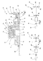
- a first embodiment of a coupling arrangement according to the invention is shown schematically in longitudinal section and generally designated 10.
- the clutch assembly 10 has a housing 12, which may be part of a housing of a vehicle transmission, for example, but may also be designed as a separate housing.
- the clutch assembly 10 includes a rotary member 14 which is rotatably supported on the housing 12 via a first radial bearing 16 and via a second radial bearing 18.
- the rotary member 14 is rotatably mounted about a longitudinal axis 20 and is formed like a basket, so that from the rotary member 14, a preferably rotationally symmetrical cavity 22 is defined.
- a coupling 24 is arranged, which is preferably designed as a wet-running multi-plate clutch and a first coupling member 26 and a second coupling member 28 has.
- the first coupling member 26 is rotatably connected to the rotary member 14.
- the rotary member 14 may form an outer disk carrier, are rotatably mounted on the lamellae of the first coupling member 26.
- the second coupling member 28 may for example be connected to an output shaft, as will be discussed below.
- the clutch assembly 10 further includes an actuator assembly 30 in the form of a fluidic actuator assembly.
- the actuator assembly 30 includes a first actuator member 32 and a second actuator member 34.
- the first actuator member 32 includes a first longitudinal portion 36 that extends axially from a portion of the housing 12 into the cavity 22. Furthermore, the first actuator member 32 has a first radial portion which is connected to the first longitudinal portion 36 and extends radially outward within the cavity 22.
- the first radial section 38 is adjacent to a radial section of the rotary member 14. Between the first radial section 38 and the rotary member 14, a first thrust bearing 40 is arranged, via which the first Actuator 32 is axially supported on the rotary member 14.
- the first longitudinal section 36 of the first actuator member 32 is rotatably fixed to the housing 12, but is preferably displaceable, in particular displaceably mounted on the housing 12.
- the second actuator member 34 has a second longitudinal portion 42 and a second radial portion 44.
- the second longitudinal section 42 is arranged concentrically to the first longitudinal section 36, wherein the first longitudinal section 36 may be provided as a hollow shaft section around the second longitudinal section 42.
- the second longitudinal portion 42 is also non-rotatably connected to the housing 12, but preferably mounted axially displaceably thereto.
- the second longitudinal portion 42 also extends into the cavity 22, such that the second radial portion 44 is disposed in the axial direction between the first radial portion 38 and the clutch 24.
- a second thrust bearing 46 is arranged, via which the clutch 24 can be actuated.
- a fluid channel 48 is formed, which is fluidically connected to a pressure chamber 50, which is formed between the first radial section 38 and the second radial section 44.
- a third longitudinal section 54 is formed, which engages over the first radial section 38.
- a first seal 52 is arranged, which seals the pressure chamber 50.
- the housing 12 has a sealing block 56, wherein between the seal block 56 and the first longitudinal portion 36, a second seal is provided. Finally, a third seal 60 is provided between the seal block 56 and the second longitudinal portion 42.
- the seals 52, 58, 60 can each be designed as static seals, for example in the form of ring seals such as O-ring seals.
- a fluid bore 62 is formed, which opens between the second seal 58 and the third seal 60 in the fluid channel 48 and which is connected to a schematically indicated fluid supply device 64.
- the fluid supply device 64 may provide a fluid at a preferably regulated pressure.
- the first longitudinal section 36 is presently shown as a solid shaft section, but may also be formed as a hollow shaft section.
- the second coupling member 28 forms an inner disk carrier which is connected via an unspecified web portion or the like to an output shaft 66 of the clutch assembly 10.
- the output shaft 66 extends on the actuator assembly 30 axially opposite side of the rotary member 14 from the cavity 22 out.
- the output shaft 66 may be sealed to the housing 12 via a shaft seal 68.
- the operation of the clutch assembly 10 is as follows.
- the clutch 24 is preferably a normally open friction clutch configured to connect or disconnect the rotary member 14 with the output shaft 66.
- the rotary member 14 may be driven by means of an unspecified drive order. In the open state of the clutch 24, this rotational movement is not transmitted to the output shaft 66 substantially.
- the clutch 24 is closed, the output shaft 66 rotates with the rotary member 14.
- the input and output function of rotary member 14 and output shaft 66 can also be reversed.
- a fluid is provided under pressure from the fluid supply device 64, the fluid via the fluid bore 62 and the fluid channel 48 passes into the pressure chamber 50.
- the first actuator member 32 and the second actuator member 34 are pressed away from one another in the longitudinal direction.
- the first actuator member 32 is supported on the first thrust bearing 40 on the rotary member 14, whose axial position is preferably secured by an unspecified thrust bearing (this thrust bearing function can also be provided by the first or the second radial bearing 16, 18).
- the second actuator member 34 Due to the pressure in the pressure chamber 50, the second actuator member 34 is moved toward the coupling 24, so that the fins of the first and second coupling members 26, 28 are compressed. The pressing takes place via the second thrust bearing 46 (and optionally a further pressure element).
- an optionally adjusting contact of the coupling 24 and a radial wall of the rotary member 14 can be used to establish an additional friction pair 70.
- the disk set can be pressed in the axial direction against the inner wall of the rotary member 14, wherein a frictional engagement is established, which supports the closing function of the clutch 24.
- the coupling 24 may optionally have a spring element or the like for this purpose.
- the fluid can be supplied via a fluid channel 48 between the first longitudinal section 36 and the second longitudinal section 42.
- the fluid channel 48 may also be formed in the first longitudinal section 36 or in the second longitudinal section 42.
- the longitudinal sections 36, 42 may also be formed a further channel, via which the multi-plate clutch is supplied with fluid or is discharged via the fluid from the cavity 22.
- a clutch assembly 10 of in Fig. 1 described type can be used for example in vehicle drive trains.
- An example of such a drive train is in Fig. 2 shown schematically and designated 80.
- the drive train 80 has a drive motor in the form of an internal combustion engine 82 and a starting clutch 84, which connects an output of the drive motor 82 with a speed reduction gear 86.
- An output of the speed reduction gear 86 is connected to a first differential 88 which distributes drive power to two driven wheels 90L, 90R of a first driven axle of the motor vehicle.
- the output of the speed reduction gear 86 is also connected to the powertrain 80 via a hang-on clutch 92 to a second differential 94 that is configured to distribute drive power to second driven axle driven wheels 96L, 96R.
- the clutch assembly 10 of Fig. 1 For example, it can be used as a starting clutch 84 and / or as a hang-on clutch 92.
- Fig. 3 shows a further embodiment of a drive train 80 ', which in terms of construction and operation generally the drive train 80 of Fig. 2 equivalent.
- the same elements are therefore identified by the same reference numerals. The following section essentially explains the differences.
- a twin clutch assembly 98 is provided which has a first side clutch 100 and a second side clutch 102, the outputs of which are connected to the driven wheels 96L, 96R.
- the clutch assembly 10 of Fig. 1 can also be used for each of the two side couplings 100, 102.
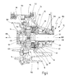
- a lockable differential with a further embodiment of a clutch assembly 10 is shown, with respect to structure and Operation of the clutch assembly 10 of Fig. 1 equivalent.
- the same elements are therefore identified by the same reference numerals. The following section essentially explains the differences.
- the lockable differential is in Fig. 4 generally designated 104.
- the lockable differential 104 is exemplified for connection to a front-transverse drive unit of a motor vehicle and is arranged coaxially to a longitudinal axis 20, which is a driven axle for driven wheels 90L, 90R.
- the lockable differential 104 is rotatably supported by means of the first radial bearing 16 on a main housing 108 of the transmission and by means of the second radial bearing 18 to a clutch housing 106.
- the lockable differential 104 has a first differential cage portion 110 and a second differential carrier portion 112, which together form a rotary member 14 having a in Fig. 4 Defined unspecified cavity.
- the differential carrier parts 110, 112 are rigidly connected to each other and to a ring gear 114 by means of a threaded connection assembly 116.
- the ring gear 114 engages a driven gear or driven wheels of the transmission.
- the coupling 24 is arranged, which is coupled via the second thrust bearing 46 with the second actuator member 34.
- a planetary gear 108 is received within the cavity 22.
- the planetary gear 118 has a ring gear 120 which is rotatably connected to the rotary member 14.
- the planetary gear set 118 includes a planet carrier 122 to which a plurality of planets are rotatably supported. The planet carrier is connected to the first coupling member 26, which is not connected to the rotary member 14 in the present embodiment.
- the planetary gear set 122 has a sun gear in the form of a hollow sun shaft 124 which is connected to the second coupling member 28.
- the hollow sun gear shaft 124 has an internal toothing, via which a drive shaft for which a driven gear 90R can be rotatably connected to the sun gear shaft 124.
- the planet carrier 122 has a shaft section which has a corresponding internal toothing for connecting a drive shaft for the other driven wheel 90L.
- the planetary gear set 122 may also be designed as a double planetary differential.
- Fig. 4 For example, the shaft seal 68 for sealing the drive shaft for the driven wheel 90L is shown schematically. Furthermore, in Fig. 4 a shaft seal 126 for sealing the housing 12 toward the drive shaft for the driven wheel 90R shown.
- the planetary gear set 118 acts as an open differential, in which the drive power is distributed to the driven wheels 90L, 90R in the manner of a torque balance, as is known in the art.
- the clutch 24 is fully or partially closed, sets a more or less large blocking effect by which the sun gear 124 and the planet carrier 122 are rigidly connected together. As a result, a blocking effect is generated, since the drive power is transmitted in equal parts to the driven wheels or in the driven wheels 90L, 90R, the same drive torque is allocated. Due to the shaft-shaft arrangement of the planetary gearset, the locking torque is equal to twice the clutch torque.
- the lockable differential 104 is formed as a closed module, which can be easily connected to a to the output of the transmission.
- the pressure chamber 50 can be realized without rotary feedthrough and without compensation spaces. Furthermore, there is a simple connection to existing housing designs.
- a dual clutch assembly 130 which serves as a start-up clutch assembly between an internal combustion engine and a stepped transmission can be arranged.
- the dual clutch assembly 130 generally corresponds in terms of construction and operation of the clutch assembly 10 of Fig. 1 , The same elements are therefore identified by the same reference numerals. The following section essentially explains the differences.
- the rotary member 14 has a receptacle for a crankshaft and thus forms a drive member of the dual clutch assembly 130.
- On the axially opposite side of the actuator assembly 30 is formed having a first actuator member 32 which is rotatably connected to a housing, not shown, and in the Cavity 22 extends into it.
- the first actuator member 32 in this case has a radial portion on which by means of two unspecified seals, a second actuator member 34A for a first clutch 24A of the dual clutch assembly 130 is axially displaceably mounted.
- a further second actuator member 34B for a second clutch 24B mounted axially displaceable and sealed by means of two unspecified seals.
- the second actuator members 34A, 34B act via respective thrust bearings 46A, 46B on the clutches 24a and 24B respectively, with a pressure member being disposed between the second thrust bearing 46B and the second clutch 24B.
- the two clutches 24A, 24B are rotatably connected at their outer periphery to the rotary member 14.
- the two clutches 24A, 24B are each connected to an output shaft 66A, 66B on their inner circumference, wherein the output shaft 66A is designed for connection to a hollow shaft of a downstream dual-clutch transmission and wherein the output shaft 66B is designed for connection to an inner shaft of the downstream dual-clutch transmission.
Abstract
- einem Drehglied (14), das an einem Gehäuse (12) um eine Längsachse (20) drehbar lagerbar ist und das einen Hohlraum (22) definiert;
- einer Kupplung (24), die ein erstes Kupplungsglied (26) und ein damit kuppelbares zweites Kupplungsglied (28) aufweist und die in dem Hohlraum (22) angeordnet ist, wobei das erste Kupplungsglied (26) oder das zweite Kupplungsglied (28) mit dem Drehglied (14) gekoppelt ist; und
- einer fluidischen Aktuatoranordnung (30), die ein erstes und ein zweites Aktuatorglied (32, 34) aufweist, die zum Betätigen der Kupplung (24) in der Längsrichtung relativ zueinander beweglich sind.
Description
- Die vorliegende Erfindung betrifft eine Kupplungsanordnung, insbesondere für einen Fahrzeugantriebsstrang, mit einem Drehglied, das an einem Gehäuse um eine Längsachse drehbar lagerbar ist und das einen Hohlraum definiert, einer Kupplung, die ein erstes Kupplungsglied und ein damit kuppelbares zweites Kupplungsglied aufweist und die in dem Hohlraum angeordnet ist, wobei das erste Kupplungsglied oder das zweite Kupplungsglied mit dem Drehglied gekoppelt ist, und mit einer fluidischen Aktuatoranordnung, die ein erstes und ein zweites Aktuatorglied aufweist, die zum Betätigen der Kupplung relativ zueinander beweglich sind.
- Derartige Kupplungsanordnungen werden beispielsweise in Fahrzeugantriebssträngen als Anfahrkupplungen verwendet, die zwischen einem Verbrennungsmotor und einem Drehzahlübersetzungsgetriebe angeordnet sind. Ferner finden derartige Kupplungsanordnungen Verwendung als Sperrkupplungen. Dies können beispielsweise sogenannte "Hang-On-Kupplungen" sein, die zur Einrichtung eines Vierradantriebes bei Bedarf eine zweite angetriebene Achse mit einer Kardanwelle oder dergleichen verbinden. Solche Sperrkupplungen können jedoch auch als Quer-Sperrkupplungen Einsatz finden, wobei beispielsweise eine rechte und eine linke Antriebswelle einer angetriebenen Achse miteinander verbindbar sind, um auf diese Weise eine Quersperrfunktion einzurichten. Ferner können solche Sperrkupplungen in Twin-Kupplungsanordnungen Verwendung finden, die einen Ausgang einer Antriebseinheit ohne mechanisches Differential mit einer linken bzw. einer rechten Antriebswelle einer angetriebenen Achse verbinden.
- Bei derartigen Sperrkupplungen sind sogenannte passive Sperrkupplungen bekannt, bei denen sich aufgrund eines Drehzahl- oder eines Drehmomentunterschiedes zwischen den Rädern oder den Achsen ein nicht beeinflussbares Sperrmoment einstellt. Hierbei zählt zu den drehzahlfühlenden Systemen die sogenannte Viscokupplung. Sogenannte Torsen-Differentiale arbeiten hingegen drehmomentfühlend.
- Ferner sind sogenannte aktive Sperren bekannt, die sich einfacher in elektronische Antriebsregelsysteme wie ABS oder ESP integrieren lassen. Aktive Sperren können unabhängig von Differenzdrehzahlen zu jeder Zeit zu- oder abgeschaltet werden, wodurch Störmomente passiver Sperrensysteme unterbunden werden, die die elektronischen Regelsysteme stören könnten. Bei den aktiven Sperrkupplungen kommen in der Regel Reibkupplungen zum Einsatz. Aufgrund der guten Dosierbarkeit und des guten Verschleißverhaltens können diese Reibkupplungen als nasse Lamellenkupplungen ausgeführt sein.
- Bei den Quer-Sperrkupplungen kann ein Drehzahlausgleich aufgrund eines mechanischen Differentials einer angetriebenen Achse gehemmt werden. Der Vorteil solcher Quer-Sperrkupplungen ist es, dass diese auch in nur mit einer Achse angetriebenen Fahrzeugen Verwendung finden können, wobei Eigenschaften erreicht werden können, die nahe an denen eines sportlichen Allradantriebes liegen. Solche Quer-Sperrkupplungen können beispielsweise als Zusatzkupplungen von außen an ein Getriebegehäuse angeflanscht und über eine Steckverzahnung drehfest mit einem Differentialkorb verbunden werden. Es ist jedoch auch bekannt, solche Quer-Sperrkupplungen in das Getriebe zu integrieren, um Bauraum, Gewicht und Montagekosten einzusparen.
- Zur Betätigung solcher Kupplungsanordnungen ist es bekannt, in einem Gehäuse einen hydraulischen Druckkolben vorzusehen, der bei Druckbeaufschlagung über eine Anordnung aus einem Axiallager und einer Druckscheibe auf die Kupplungsglieder (beispielsweise Lamellenpaket) drückt. Bei diesen Anordnungen bildet die Kupplungsanordnung kein in sich geschlossenes System, was das Handling bei der Integration aufwändig macht und Änderungen am Getriebegehäuse bedingt. Dies wiederum hat höhere Produktionskosten zur Folge.
- Ferner sind Konzepte bekannt, die auf einen rotierenden Druckkolben setzen. Hierbei wird über eine sogenannte Drehdurchführung der Hydraulikdruck von einem Gehäuse, in dem sich eine Druckquelle befindet, an die rotierende Sperrkupplung und den darin integrierten Druckkolben übergeben. Bei dieser Ausführungsform sind keine Axiallager notwendig. Bei der Verwendung eines solchen mitlaufenden Kolbens kann die Kupplungsanordnung als in sich geschlossenes System ausgebildet werden, das unter Verwendung klar definierter vorhandener Schnittstellen in ein Getriebe integriert werden kann. Die benötigte Drehdurchführung ist technisch jedoch sehr anspruchsvoll und in der Regel mit einer relativ hohen Leckagerate verbunden. Dies macht die Verwendung einer gemeinsamen Druckquelle bei Integration in ein vorhandenes Getriebe schwierig. Ferner ist die Kompensation auftretender Fliehkräfte in dem Druckkolben konstruktiv aufwändig und daher teuer.
- Zur Betätigung solcher Kupplungsanordnungen ist es auch bekannt, Kugelrampensysteme ("ETM") zu verwenden. Bei diesen Kugelrampensystemen treibt ein Elektromotor über eine starke Übersetzung eine Kugelrampe an. Durch die Steigung in der Kugelbahn wird eine Axialkraft erzeugt, die ein Lamellenpaket zusammendrückt und hierdurch die Drehmomentübertragung ermöglicht.
- Derartige Kugelrampensysteme können zwar axial sehr kurz ausgeführt werden, aufgrund der mechanischen Kraftübertragung muss der relativ große Elektromotor jedoch in unmittelbarer Nähe zum Kupplungssystem verbaut werden.
- Ferner ist es bekannt, Kupplungsanordnungen über eine elektromagnetisch aktuierte Vorsteuerkupplung zu betätigen. Die Vorsteuerkupplung kann einen Abschnitt der Kugelrampe abbremsen, wodurch eine Relativdrehzahl in der Kugelrampe bewirkt wird. Hierdurch kann die Kugelrampe das eigentliche Kupplungspaket mit Kraft beaufschlagen und die Sperrwirkung erzeugen bzw. die Kupplung schließen.
- Derartige Aktuatoranordnungen mit Kugelrampe und elektromagnetisch betätigter Vorsteuerkupplung bauen jedoch axial sehr groß, was die Integration in Antriebsstränge schwierig macht.
- Vor diesem Hintergrund ist es eine Aufgabe der Erfindung, eine Kupplungsanordnung bereitzustellen, die gut in einem Fahrzeugantriebsstrang integriert werden kann und/oder die als geschlossenes System bzw. Modul ausgebildet werden kann.
- Diese Aufgabe wird bei der eingangs genannten Kupplungsanordnung dadurch gelöst, dass zumindest das erste Aktuatorglied drehfest an dem Gehäuse festlegbar ist und sich von außerhalb des Drehgliedes in den Hohlraum hinein erstreckt.
- Durch diese Maßnahme kann erreicht werden, dass die Reibkupplung als in sich geschlossenes Modul ausgebildet werden kann, so dass sich eine verbesserte Integrierbarkeit in Fahrzeugantriebsstränge ergibt.
- Gemäß einer besonders bevorzugten Ausführungsform stützt sich das erste Aktuatorglied innerhalb des Hohlraumes über ein erstes Axiallager an dem Drehglied ab.
- Bei dieser Ausführungsform ist zumindest das erste Aktuatorglied vorzugsweise axial verschieblich in Bezug auf das Gehäuse festlegbar.
- Vorzugsweise weist das erste Aktuatorglied hierbei einen Längsabschnitt auf, der sich von dem Gehäuse aus in den Hohlraum hinein erstreckt, sowie einen Radialabschnitt, mittels dessen sich das erste Aktuatorglied innerhalb des Hohlraumes über das erste Axiallager an dem Drehglied abstützen kann.
- Von besonderem Vorzug ist es ferner, wenn auch das zweite Aktuatorglied drehfest an dem Gehäuse festlegbar ist und sich von außerhalb des Drehgliedes in den Hohlraum hinein erstreckt.
- Hierdurch kann die Aktuatorik konstruktiv einfach in den Hohlraum hinein verlagert werden, so dass sich ein geschlossenes Modul für die Kupplungsanordnung ergibt.
- Das zweite Aktuatorglied ist in Bezug auf das Gehäuse vorzugsweise ebenfalls axial verschieblich gelagert (beispielsweise über eine Steckverzahnung oder dergleichen).
- Ferner ist es bevorzugt, wenn das zweite Aktuatorglied über ein zweites Axiallager an der Reibkupplung angreift.
- Auch das zweite Aktuatorglied weist vorzugsweise einen Längsabschnitt auf, der sich von dem Gehäuse aus in den Hohlraum hinein erstreckt, sowie einen Radialabschnitt, der über das zweite Axiallager an der Reibkupplung angreift.
- Durch diese Maßnahme können innerhalb des Hohlraumes Axialkräfte auf die Kupplung aufgebracht werden.
- Gemäß einer weiteren insgesamt bevorzugten Ausführungsform, die in Verbindung mit der eingangs genannten Kupplungsanordnung eine eigene Erfindung darstellt, ist innerhalb des Hohlraumes zwischen dem ersten und dem zweiten Aktuatorglied ein Druckraum ausgebildet, der über einen Fluidkanal mit einer gehäusefesten Fluidversorgungseinrichtung verbindbar ist, wobei der Fluidkanal in einem der Aktuatorglieder und/oder zwischen dem ersten Aktuatorglied und dem zweiten Aktuatorglied ausgebildet ist.
- Hierdurch kann das Fluid von der gehäusefesten Fluidversorgungseinrichtung (die beispielsweise über Druckregeleinrichtungen etc. verfügt) in den Druckraum geleitet werden. Ferner kann die Aktuatoranordnung ohne Drehdurchführung realisiert werden. Das Fluid kann über das Gehäuse in das Innere des Hohlraumes zugeführt werden, wobei eine Abdichtung des ersten und/oder des zweiten Aktuatorgliedes gegenüber dem Gehäuse auf einfache Weise über Ringdichtungen wie O-Ring-Dichtungen oder dergleichen erfolgen kann.
- Vorzugsweise ist zur Abdichtung des Druckraumes innerhalb des Hohlraumes zwischen dem ersten und dem zweiten Aktuatorglied eine Dichtung vorgesehen, die ebenfalls einfach als O-Ring-Dichtung oder dergleichen ausgebildet sein kann. Hierzu kann es auch vorteilhaft sein, wenn eines der Aktuatorglieder an dem freien Ende des Radialabschnittes einen weiteren Längsabschnitt aufweist, der den Radialabschnitt des anderen Aktuatorgliedes übergreift, wobei in diesem Bereich die Abdichtung vorgesehen sein kann.
- Ferner ist es insgesamt vorteilhaft, wenn der Hohlraum gegenüber der Umgebung und/oder gegenüber der fluidischen Aktuatoranordnung abdichtbar ist. Bei dieser Ausführungsform kann das den Hohlraum bildende Drehglied die "Außenhülle" des geschlossenen Kupplungsanordnungsmoduls bilden, innerhalb derselben ein Druckraum der Aktuatoranordnung ausgebildet ist.
- Da der Hohlraum auch gegenüber der fluidischen Aktuatoranordnung abgedichtet sein kann, ist es auch möglich, mittels der fluidischen Aktuatoranordnung eine trockene Reibkupplung zu betätigen, wobei die Kupplung vorzugsweise als nasslaufende Lamellenkupplung ausgebildet ist.
- Generell ist es möglich, das erste oder das zweite Kupplungsglied starr mit dem Drehglied zu koppeln.
- Besonders bevorzugt ist es jedoch, wenn das erste Kupplungsglied über eine Radsatzanordnung mit dem Drehglied gekoppelt ist.
- Bei dieser Ausführungsform kann die Radsatzanordnung eine Übersetzung zwischen dem Drehglied und dem ersten Kupplungsglied einrichten. Ferner ist es möglich, die Radsatzanordnung als mechanisches Differential auszubilden, derart, dass die Kupplungsanordnung als Quer- oder Längssperre eines Drehmoment verteilenden Differentials eines Antriebsstrangs sein kann.
- Demzufolge wird die obige Aufgabe ebenfalls gelöst durch ein sperrbares Differential mit einem Gehäuse und mit einer Kupplungsanordnung der erfindungsgemäßen Art, wobei das erste Kupplungsglied über eine Radsatzanordnung mit dem Drehglied gekoppelt ist, wobei die Radsatzanordnung eine Umlaufradsatzanordnung mit einem ersten Radsatzglied, einem zweiten Radsatzglied und mit einem dritten Radsatzglied ist, wobei das erste Radsatzglied mit dem einen Eingang des Differentials bildenden Drehglied verbunden ist, wobei das zweite und das dritte Radsatzglied Ausgänge des Differentials bilden und wobei das erste Kupplungsglied mit dem zweiten Radsatzglied verbunden ist, und wobei das zweite Kupplungsglied mit dem dritten Radsatzglied verbunden ist.
- Ein derartiges sperrbares Differential lässt sich auf einfache Weise in dem Bauraum vorsehen, der beispielsweise bei Front-Quer-Getrieben für ein Differential ohnehin vorgesehen ist. Der Antrieb des sperrbaren Differentials kann erfolgen, indem das Drehglied, das vorliegend eine Art Differentialkorb bildet, mit einem Zahnrad verbunden ist, das mit dem Ausgang einer Antriebseinheit (beispielsweise Verbrennungsmotor und Drehzahlübersetzungsgetriebe) verbunden sein kann.
- Bei dem sperrbaren Differential ist es generell möglich, dass die Kupplungsanordnung nach der Art einer Klauenkupplung ausgebildet ist.
- Von besonderem Vorzug ist es jedoch, wenn die Kupplung eine Reibkupplung ist, insbesondere eine nasslaufende Lamellenkupplung.
- In diesem Fall ist es ferner vorteilhaft, wenn das zweite Getriebeglied oder das zweite Radsatzglied mit dem Drehglied eine zusätzliche Reibpaarung bildet.
- Hierdurch kann die zur Abstützung der Kupplungsanordnung an der dem Druckraum gegenüberliegenden axialen Seite erforderliche Kontaktfläche genutzt werden, um eine zusätzliche Reibpaarung zu bilden, so dass die Reibkupplung selbst kleiner dimensioniert werden kann und/oder der benötigte Aktivierungsdruck verringert werden kann und/oder ein weiteres Axiallager eingespart werden kann.
- Insgesamt ist es erfindungsgemäß bevorzugt, wenn die Kupplungsanordnung der erfindungsgemäßen Art als Hang-On-Kupplung für einen Allrad-Antriebsstrang oder als Kupplung einer Doppelkupplungsanordnung eines Doppelkupplungsgetriebes oder als Kupplung einer Twin-Kupplungsanordnung zum Verteilen von Antriebsmoment auf angetriebene Räder einer angetriebenen Achse eines Kraftfahrzeuges verwendet wird.
- Insgesamt lässt sich ferner je nach Ausführungsform wenigstens einer der folgenden Vorteile durch die Erfindung realisieren.
- Zum einen kann eine stehende hydraulisch-aktuierbare Druckkolbenkonstruktion in einer rotierenden Kupplungsanordnung bereitgestellt werden, die vorzugsweise als Sperr-Kupplungsanordnung ausgebildet ist.
- Es ergibt sich hierdurch ein geschlossenes Modul, das unter Verwendung vorhandener Schnittstellen ohne nennenswerten Änderungsaufwand in ein Fahrzeuggetriebe integriert werden kann. Die Druckübergabe an den Druckkolben befindet sich im Betrieb in einem statischen Zustand, was die Konstruktion einfach und kostengünstig hält. Eine Fliehkraftkompensation wird nicht benötigt. Die Druckübergabe kann beispielsweise in den Sitz eines Radialwellendichtringes an einem Differentialgehäuse eingebracht, insbesondere eingepresst werden. Bei dieser Ausführungsform sind die Änderungen am Getriebe minimierbar.
- Bei Integration in ein Doppelkupplungsgetriebe kann die vorhandene Druckquelle des Getriebes verwendet werden, so dass lediglich ein zusätzliches Drucksteuer- bzw. Druckregelventil und gegebenenfalls ein Steuergerät erforderlich sind.
- Es wird ein in sich geschlossenes Kupplungsanordnungs-System mit einer Leckagerate wie bei einem System mit stehendem Kolben ermöglicht. Die Kupplungsanordnungs-Konstruktion ist einfach, was Vorteile hinsichtlich der Entwicklungs- und Produktionskosten mit sich bringt. Die statischen Dichtungen im Bereich der Druckübergabe haben im Vergleich mit einer Drehdurchführung keinen Verschleiß über die Lebensdauer.
- Ferner kann die statische Druckübergabe im Gehäuse des Getriebes vorgesehen werden, wodurch mindestens ein Bauteil entfällt.
- Des Weiteren kann eine kompakte Bauweise realisiert werden.
- Es versteht sich, dass die vorstehend genannten und die nachstehend noch zu erläuternden Merkmale nicht nur in der jeweils angegebenen Kombination, sondern auch in anderen Kombinationen oder in Alleinstellung verwendbar sind, ohne den Rahmen der vorliegenden Erfindung zu verlassen.
- Ausführungsbeispiele der Erfindung sind in der Zeichnung dargestellt und werden in der nachfolgenden Beschreibung näher erläutert. Es zeigen:
- Fig. 1
- eine schematische Längsschnittansicht durch eine Kupplungsanordnung gemäß einer Ausführungsform der vorliegenden Erfindung;
- Fig. 2
- einen Antriebsstrang eines Kraftfahrzeuges mit einer Anfahrkupplung und einer Hang-On-Kupplung;
- Fig. 3
- einen Antriebsstrang eines Kraftfahrzeuges mit einer Anfahrkupplung und zwei Kupplungen einer Twin-Kupplungsanordnung;
- Fig. 4
- eine Längsschnittansicht durch eine Ausführungsform eines sperrbaren Differentials; und
- Fig. 5
- eine schematische Längsschnittansicht durch eine Doppelkupplungsanordnung mit zwei erfindungsgemäßen Kupplungsanordnungen.
- In
Fig. 1 ist eine erste Ausführungsform einer erfindungsgemäßen Kupplungsanordnung schematisch im Längsschnitt dargestellt und generell mit 10 bezeichnet. - Die Kupplungsanordnung 10 weist ein Gehäuse 12 auf, das beispielsweise Teil eines Gehäuses eines Fahrzeuggetriebes sein kann, jedoch auch als eigenes Gehäuse ausgebildet sein kann.
- Ferner beinhaltet die Kupplungsanordnung 10 ein Drehglied 14, das über ein erstes Radiallager 16 und über ein zweites Radiallager 18 drehbar an dem Gehäuse 12 gelagert ist. Alternativ ist auch eine Lagerung an einer Wellenanordnung denkbar. Das Drehglied 14 ist dabei um eine Längsachse 20 drehbar gelagert und ist korbartig ausgebildet, so dass von dem Drehglied 14 ein vorzugsweise rotationssymmetrischer Hohlraum 22 definiert wird.
- Innerhalb des Hohlraumes 22 ist eine Kupplung 24 angeordnet, die vorzugsweise als nasslaufende Lamellenkupplung ausgebildet ist und ein erstes Kupplungsglied 26 und ein zweites Kupplungsglied 28 aufweist. Im vorliegenden Fall ist das erste Kupplungsglied 26 drehfest mit dem Drehglied 14 verbunden. Wie dargestellt, kann das Drehglied 14 dabei einen Außenlamellenträger bilden, an dem Lamellen des ersten Kupplungsgliedes 26 drehfest gelagert sind.
- Das zweite Kupplungsglied 28 kann beispielsweise mit einer Ausgangswelle verbunden sein, worauf nachstehend noch eingegangen werden wird.
- Die Kupplungsanordnung 10 beinhaltet ferner eine Aktuatoranordnung 30 in Form einer fluidischen Aktuatoranordnung. Die Aktuatoranordnung 30 beinhaltet ein erstes Aktuatorglied 32 und ein zweites Aktuatorglied 34. Das erste Aktuatorglied 32 weist einen ersten Längsabschnitt 36 auf, der sich in axialer Richtung von einem Abschnitt des Gehäuses 12 in den Hohlraum 22 hinein erstreckt. Ferner weist das erste Aktuatorglied 32 einen ersten Radialabschnitt auf, der mit dem ersten Längsabschnitt 36 verbunden ist und sich innerhalb des Hohlraumes 22 radial nach außen erstreckt. Der erste Radialabschnitt 38 ist dabei benachbart zu einem Radialabschnitt des Drehgliedes 14. Zwischen dem ersten Radialabschnitt 38 und dem Drehglied 14 ist ein erstes Axiallager 40 angeordnet, über das sich das erste Aktuatorglied 32 an dem Drehglied 14 axial abstützt. Der erste Längsabschnitt 36 des ersten Aktuatorgliedes 32 ist drehfest an dem Gehäuse 12 festgelegt, ist jedoch vorzugsweise verschieblich, insbesondere begrenzt verschieblich an dem Gehäuse 12 gelagert.
- Das zweite Aktuatorglied 34 weist einen zweiten Längsabschnitt 42 und einen zweiten Radialabschnitt 44 auf. Der zweite Längsabschnitt 42 ist konzentrisch zu dem ersten Längsabschnitt 36 angeordnet, wobei der erste Längsabschnitt 36 als Hohlwellenabschnitt um den zweiten Längsabschnitt 42 herum vorgesehen sein kann.
- Der zweite Längsabschnitt 42 ist ebenfalls drehfest mit dem Gehäuse 12 verbunden, jedoch vorzugsweise axial verschieblich hieran gelagert. Der zweite Längsabschnitt 42 erstreckt sich ebenfalls in den Hohlraum 22 hinein, derart, dass der zweite Radialabschnitt 44 in axialer Richtung zwischen dem ersten Radialabschnitt 38 und der Kupplung 24 angeordnet ist. Zwischen dem zweiten Radialabschnitt 44 und der Kupplung 24 ist ein zweites Axiallager 46 angeordnet, über das die Kupplung 24 betätigbar ist.
- Zwischen dem ersten Längsabschnitt 36 und dem zweiten Längsabschnitt 42 ist ein Fluidkanal 48 ausgebildet, der mit einem Druckraum 50 fluidisch verbunden ist, der zwischen dem ersten Radialabschnitt 38 und dem zweiten Radialabschnitt 44 ausgebildet ist. Am radial äußeren Ende des ersten Radialabschnittes 38 ist ein dritter Längsabschnitt 54 ausgebildet, der den ersten Radialabschnitt 38 übergreift. Zwischen dem dritten Längsabschnitt 54 und dem ersten Radialabschnitt 38 ist eine erste Dichtung 52 angeordnet, die den Druckraum 50 abdichtet.
- Das Gehäuse 12 weist einen Dichtungsblock 56 auf, wobei zwischen dem Dichtungsblock 56 und dem ersten Längsabschnitt 36 eine zweite Dichtung vorgesehen ist. Schließlich ist zwischen dem Dichtungsblock 56 und dem zweiten Längsabschnitt 42 eine dritte Dichtung 60 vorgesehen. Die Dichtungen 52, 58, 60 können jeweils als statische Dichtungen ausgebildet sein, beispielsweise in Form von Ringdichtungen wie O-Ring-Dichtungen.
- In dem Dichtungsblock 56 ist eine Fluidbohrung 62 ausgebildet, die zwischen der zweiten Dichtung 58 und der dritten Dichtung 60 in den Fluidkanal 48 mündet und die mit einer schematisch angedeuteten Fluidversorgungseinrichtung 64 verbunden ist. Die Fluidversorgungseinrichtung 64 kann ein Fluid mit einem vorzugsweise geregelten Druck bereitstellen.
- Der erste Längsabschnitt 36 ist vorliegend als Vollwellenabschnitt dargestellt, kann jedoch auch als Hohlwellenabschnitt ausgebildet sein.
- Das zweite Kupplungsglied 28 bildet einen Innenlamellenträger, der über einen nicht näher bezeichneten Stegabschnitt oder dergleichen mit einer Ausgangswelle 66 der Kupplungsanordnung 10 verbunden ist. Die Ausgangswelle 66 erstreckt sich auf der der Aktuatoranordnung 30 axial gegenüberliegenden Seite des Drehgliedes 14 aus dem Hohlraum 22 heraus. Die Ausgangswelle 66 kann über eine Wellendichtung 68 gegenüber dem Gehäuse 12 abgedichtet sein.
- Die Funktionsweise der Kupplungsanordnung 10 ergibt sich wie folgt. Die Kupplung 24 ist vorzugsweise eine normalerweise offene Reibkupplung, die dazu ausgelegt ist, das Drehglied 14 mit der Ausgangswelle 66 zu verbinden oder hiervon zu trennen. Das Drehglied 14 kann mittels einer nicht näher bezeichneten Antriebsordnung antreibbar sein. Im geöffneten Zustand der Kupplung 24 wird diese Drehbewegung im Wesentlichen nicht auf die Ausgangswelle 66 übertragen. Wenn die Kupplung 24 geschlossen ist, dreht die Ausgangswelle 66 mit dem Drehglied 14 mit. Die Eingangs- und Ausgangsfunktion von Drehglied 14 und Ausgangswelle 66 können auch vertauscht werden.
- Zum Schließen der Kupplung 24 wird von der Fluidversorgungseinrichtung 64 ein Fluid unter Druck bereitgestellt, das über die Fluidbohrung 62 und den Fluidkanal 48 in den Druckraum 50 gelangt. Durch den sich in den Druckraum 50 aufbauenden Druck werden das erste Aktuatorglied 32 und das zweite Aktuatorglied 34 in Längsrichtung voneinander weg gedrückt. Das erste Aktuatorglied 32 stützt sich dabei über das erste Axiallager 40 an dem Drehglied 14 ab, dessen axiale Position vorzugsweise über ein nicht näher bezeichnetes Axiallager gesichert ist (diese Axiallagerfunktion kann auch durch das erste oder das zweite Radiallager 16, 18 bereitgestellt werden).
- Durch den Druck in dem Druckraum 50 wird das zweite Aktuatorglied 34 auf die Kupplung 24 zu bewegt, so dass die Lamellen des ersten und des zweiten Kupplungsgliedes 26, 28 zusammengedrückt werden. Das Andrücken erfolgt dabei über das zweite Axiallager 46 (und gegebenenfalls ein weiteres Andruckelement).
- Dabei kann ein sich gegebenenfalls einstellender Kontakt der Kupplung 24 und einer Radialwand des Drehgliedes 14 zur Einrichtung einer zusätzlichen Reibpaarung 70 verwendet werden. Mit anderen Worten kann das Lamellenpaket in axialer Richtung gegen die Innenwand des Drehgliedes 14 angedrückt werden, wobei sich ein Reibeingriff einstellt, der die Schließfunktion der Kupplung 24 unterstützt.
- Zum Öffnen der Kupplung 24 wird der Druck in dem Druckraum 50 wieder abgebaut, so dass sich die Kupplung 24 öffnen kann. Die Kupplung 24 kann hierzu gegebenenfalls ein Federelement oder dergleichen aufweisen.
- Das Fluid kann wie dargestellt über einen Fluidkanal 48 zwischen dem ersten Längsabschnitt 36 und dem zweiten Längsabschnitt 42 zugeführt werden. Alternativ kann der Fluidkanal 48 auch in dem ersten Längsabschnitt 36 oder in dem zweiten Längsabschnitt 42 ausgebildet sein. In einem der Längsabschnitte 36, 42 kann ferner ein weiterer Kanal ausgebildet sein, über den die Lamellenkupplung mit Fluid versorgt wird oder über den Fluid aus dem Hohlraum 22 abgeführt wird.
- Eine Kupplungsanordnung 10 der in
Fig. 1 beschriebenen Art lässt sich beispielsweise in Fahrzeugantriebssträngen verwenden. Ein Beispiel eines solchen Antriebsstranges ist inFig. 2 schematisch dargestellt und mit 80 bezeichnet. - Der Antriebsstrang 80 weist einen Antriebsmotor in Form eines Verbrennungsmotors 82 sowie eine Anfahrkupplung 84 auf, die einen Ausgang des Antriebsmotors 82 mit einem Drehzahlübersetzungsgetriebe 86 verbindet. Ein Ausgang des Drehzahlübersetzungsgetriebes 86 ist mit einem ersten Differential 88 verbunden, das Antriebsleistung auf zwei angetriebene Räder 90L, 90R einer ersten angetriebenen Achse des Kraftfahrzeuges verteilt. Der Ausgang des Drehzahlübersetzungsgetriebes 86 ist bei dem Antriebsstrang 80 ferner über eine Hang-On-Kupplung 92 mit einem zweiten Differential 94 verbunden, das dazu ausgelegt ist, Antriebsleistung auf angetriebene Räder 96L, 96R einer zweiten angetriebenen Achse zu verteilen.
- Die Kupplungsanordnung 10 der
Fig. 1 lässt sich beispielsweise als Anfahrkupplung 84 und/oder als Hang-On-Kupplung 92 verwenden. -
Fig. 3 zeigt eine weitere Ausführungsform eines Antriebsstranges 80', der hinsichtlich Aufbau und Funktionsweise generell dem Antriebsstrang 80 derFig. 2 entspricht. Gleiche Elemente sind daher durch gleiche Bezugszeichen gekennzeichnet. Im Folgenden werden im Wesentlichen die Unterschiede erläutert. - Bei dem Antriebsstrang 80' der
Fig. 3 ist anstelle des zweiten Differentials 94 eine Twin-Kupplungsanordnung 98 vorgesehen, die eine erste Seitenkupplung 100 und eine zweite Seitenkupplung 102 aufweist, deren Ausgänge mit den angetriebenen Rädern 96L, 96R verbunden sind. Die Kupplungsanordnung 10 derFig. 1 lässt sich auch für jede der zwei Seitenkupplungen 100, 102 verwenden. - In
Fig. 4 ist ein sperrbares Differential mit einer weiteren Ausführungsform einer Kupplungsanordnung 10 dargestellt, die hinsichtlich Aufbau und Funktionsweise der Kupplungsanordnung 10 derFig. 1 entspricht. Gleiche Elemente sind daher durch gleiche Bezugszeichen gekennzeichnet. Im Folgenden werden im Wesentlichen die Unterschiede erläutert. - Das sperrbare Differential ist in
Fig. 4 generell mit 104 bezeichnet. Das sperrbare Differential 104 ist beispielhaft für die Anbindung an eine Front-Quer-Antriebseinheit eines Kraftfahrzeuges ausgelegt und ist koaxial zu einer Längsachse 20 angeordnet, die eine angetriebene Achse für angetriebene Räder 90L, 90R darstellt. Das sperrbare Differential 104 ist mittels des ersten Radiallagers 16 an einem Hauptgehäuse 108 des Getriebes und mittels des zweiten Radiallagers 18 an einem Kupplungsgehäuse 106 drehbar gelagert. Das sperrbare Differential 104 weist ein erstes Differentialkorbteil 110 und ein zweites Differentialkorbteil 112 auf, die gemeinsam ein Drehglied 14 bilden, das einen inFig. 4 nicht näher bezeichneten Hohlraum definiert. Die Differentialkorbteile 110, 112 sind starr miteinander und mit einem Tellerrad 114 verbunden, und zwar mittels einer Schraubverbindungsanordnung 116. Das Tellerrad 114 steht in Eingriff mit einem Abtriebsrad oder mit Abtriebsrädern des Getriebes. - In dem Hohlraum 22 des Drehgliedes 14 ist die Kupplung 24 angeordnet, die über das zweite Axiallager 46 mit dem zweiten Aktuatorglied 34 gekoppelt ist. An der der Aktuatoranordnung 30 abgewandten Seite der Kupplung 24 ist innerhalb des Hohlraumes 22 ein Planetenradsatz 108 aufgenommen. Der Planetenradsatz 118 weist ein Hohlrad 120 auf, das drehfest mit dem Drehglied 14 verbunden ist. Ferner beinhaltet der Planetenradsatz 118 einen Planetenträger 122, an dem eine Mehrzahl von Planeten drehbar gelagert ist. Der Planetenträger ist mit dem ersten Kupplungsglied 26 verbunden, das in der vorliegenden Ausführungsform nicht mit dem Drehglied 14 verbunden ist.
- Ferner weist der Planetenradsatz 122 ein Sonnenrad in Form einer hohlen Sonnenwelle 124 auf, die mit dem zweiten Kupplungsglied 28 verbunden ist. Die hohle Sonnenradwelle 124 weist eine Innenverzahnung auf, über die eine Antriebswelle für das eine angetriebene Rad 90R drehfest mit der Sonnenradwelle 124 verbunden werden kann. Ferner weist der Planetenträger 122 einen Wellenabschnitt auf, der eine entsprechende Innenverzahnung zur Anbindung einer Antriebswelle für das andere angetriebene Rad 90L aufweist. Der Planetenradsatz 122 kann auch als Doppelplanetendifferential ausgeführt sein.
- In
Fig. 4 ist der Wellendichtring 68 zum Abdichten der Antriebswelle für das angetriebene Rad 90L schematisch dargestellt. Ferner ist inFig. 4 eine Wellendichtung 126 zum Abdichten des Gehäuses 12 hin zu der Antriebswelle für das angetriebene Rad 90R dargestellt. - Wenn die Kupplung 24 geöffnet ist, wirkt der Planetenradsatz 118 als offenes Differential, bei dem die Antriebsleistung auf die angetriebenen Räder 90L, 90R nach der Art einer Drehmomentwaage verteilt wird, wie es im Stand der Technik bekannt ist. Wenn die Kupplung 24 ganz oder teilweise geschlossen wird, setzt eine mehr oder weniger große Sperrwirkung ein, durch die das Sonnenrad 124 und der Planetenträger 122 starr miteinander verbunden werden. Hierdurch wird eine Sperrwirkung erzeugt, da die Antriebsleistung zu gleichen Teilen auf die angetriebenen Räder übertragen wird bzw. bei den angetriebenen Rädern 90L, 90R das gleiche Antriebsmoment zugeteilt wird. Durch die Welle-Welle-Anordnung des Planetenradsatzes ist das Sperrmoment gleich dem doppelten Kupplungsmoment.
- Dadurch, dass die Aktuatoranordnung in das Drehglied 14 integriert ist, ist das sperrbare Differential 104 als geschlossenes Modul ausgebildet, das auf einfache Weise zum einen an den Ausgang des Getriebes angebunden werden kann. Zum anderen kann der Druckraum 50 ohne Drehdurchführung und ohne Ausgleichsräume realisiert werden. Ferner ergibt sich eine einfache Anbindung an bereits existierende Gehäusekonstruktionen.
- In
Fig. 5 ist in schematischer Form eine Doppelkupplungsanordnung 130 dargestellt, die als Anfahrkupplungsanordnung zwischen einem Verbrennungsmotor und einem Stufengetriebe angeordnet werden kann. Die Doppelkupplungsanordnung 130 entspricht hinsichtlich Aufbau und Funktionsweise generell der Kupplungsanordnung 10 derFig. 1 . Gleiche Elemente sind daher durch gleiche Bezugszeichen gekennzeichnet. Im Folgenden werden im Wesentlichen die Unterschiede erläutert. - Das Drehglied 14 weist eine Aufnahme für eine Kurbelwelle auf und bildet folglich ein Antriebsglied der Doppelkupplungsanordnung 130. Auf der axial gegenüberliegenden Seite ist die Aktuatoranordnung 30 ausgebildet, die ein erstes Aktuatorglied 32 aufweist, das mit einem nicht dargestellten Gehäuse drehfest verbunden ist und sich in den Hohlraum 22 hinein erstreckt. Das erste Aktuatorglied 32 weist dabei einen Radialabschnitt auf, an dem mittels zweier nicht näher bezeichneter Dichtungen ein zweites Aktuatorglied 34A für eine erste Kupplung 24A der Doppelkupplungsanordnung 130 axial verschieblich gelagert ist. Ferner ist radial weiter innen liegend an dem ersten Aktuatorglied 32 ein weiteres zweites Aktuatorglied 34B für eine zweite Kupplung 24B axial verschieblich gelagert und mittels zweier nicht näher bezeichneter Dichtungen abgedichtet. Die zweiten Aktuatorglieder 34A, 34B wirken über jeweilige Axiallager 46A, 46B auf die Kupplungen 24a bzw. 24B, wobei zwischen dem zweiten Axiallager 46B und der zweiten Kupplung 24B ein Andruckglied angeordnet ist.
- Die zwei Kupplungen 24A, 24B sind an ihrem Außenumfang jeweils drehfest mit dem Drehglied 14 verbunden. An ihrem Innenumfang sind die zwei Kupplungen 24A, 24B jeweils mit einer Ausgangswelle 66A, 66B verbunden, wobei die Ausgangswelle 66A zur Anbindung an eine Hohlwelle eines nachgeschalteten Doppelkupplungsgetriebes ausgebildet ist und wobei die Ausgangswelle 66B zur Anbindung an eine Innenwelle des nachgeschalteten Doppelkupplungsgetriebes ausgebildet ist.
Claims (9)
- Kupplungsanordnung (10), insbesondere für einen Fahrzeugantriebsstrang (80), mit- einem Drehglied (14), das an einem Gehäuse (12) um eine Längsachse (20) drehbar lagerbar ist und das einen Hohlraum (22) definiert;- einer Kupplung (24), die ein erstes Kupplungsglied (26) und ein damit kuppelbares zweites Kupplungsglied (28) aufweist und die in dem Hohlraum (22) angeordnet ist, wobei das erste Kupplungsglied (26) oder das zweite Kupplungsglied (28) mit dem Drehglied (14) gekoppelt ist; und- einer fluidischen Aktuatoranordnung (30), die ein erstes und ein zweites Aktuatorglied (32, 34) aufweist, die zum Betätigen der Kupplung (24) relativ zueinander beweglich sind;
dadurch gekennzeichnet, dass
zumindest das erste Aktuatorglied (32) drehfest an dem Gehäuse (12) festlegbar ist und sich von außerhalb des Drehgliedes (14) in den Hohlraum (22) hinein erstreckt. - Kupplungsanordnung nach Anspruch 1, dadurch gekennzeichnet, dass das erste Aktuatorglied (32) sich innerhalb des Hohlraumes (22) über ein erstes Axiallager (40) an dem Drehglied (14) abstützt.
- Kupplungsanordnung nach Anspruch 1 oder 2, dadurch gekennzeichnet, dass das zweite Aktuatorglied (34) über ein zweites Axiallager (46) an der Reibkupplung angreift.
- Kupplungsanordnung nach einem der Ansprüche 1 bis 3 oder nach dem Oberbegriff des Anspruchs 1, dadurch gekennzeichnet, dass innerhalb des Hohlraumes (22) zwischen dem ersten und dem zweiten Aktuatorglied (32, 34) ein Druckraum (50) ausgebildet ist, der über einen Fluidkanal (48) mit einer gehäusefesten Fluidversorgungseinrichtung (64) verbindbar ist, wobei der Fluidkanal (48) in einem der Aktuatorglieder (32) und/oder zwischen dem ersten Aktuatorglied (32) und dem zweiten Aktuatorglied (34) ausgebildet ist.
- Kupplungsanordnung nach einem der Ansprüche 1 bis 4, dadurch gekennzeichnet, dass der Hohlraum (22) gegenüber der Umgebung und/oder gegenüber der fluidischen Aktuatoranordnung (30) abdichtbar ist.
- Kupplungsanordnung nach einem der Ansprüche 1 bis 5, dadurch gekennzeichnet, dass das erste Kupplungsglied (26) über eine Radsatzanordnung (118) mit dem Drehglied (14) gekoppelt ist.
- Sperrbares Differential (104) mit einem Gehäuse (12) und mit einer Kupplungsanordnung (10) nach Anspruch 6, wobei die Radsatzanordnung (118) eine Umlaufradsatzanordnung mit einem ersten Radsatzglied (120), einem zweiten Radsatzglied (122) und mit einem dritten Radsatzglied (124) ist, wobei das erste Radsatzglied (120) mit dem einen Eingang des Differentials (104) bildenden Drehglied (14) verbunden ist, wobei das zweite und das dritte Radsatzglied (122, 124) Ausgänge des Differentials (104) bilden und wobei das erste Kupplungsglied (26) mit dem zweiten Radsatzglied (122) und das zweite Kupplungsglied (28) mit dem dritten Radsatzglied (124) verbunden sind.
- Sperrbares Differential nach Anspruch 7, wobei die Kupplung (10) eine Reibkupplung ist und wobei das zweite Kupplungsglied (28) oder das zweite Radsatzglied (122) mit dem Drehglied (14) eine zusätzliche Reibpaarung (70) bildet.
- Verwendung einer Kupplungsanordnung (10) nach einem der Ansprüche 1 bis 6 als Hang-On-Kupplung (92) für einen Allrad-Antriebsstrang (80) oder als Kupplung (24A, 24B) einer Doppelkupplungsanordnung (130) eines Doppelkupplungsgetriebes oder als Kupplung (100, 102) einer Twin-Kupplungsanordnung (98) zum Verteilen von Antriebsmoment auf angetriebene Räder (96L, 96R) einer angetriebenen Achse eines Kraftfahrzeuges.
Applications Claiming Priority (1)
| Application Number | Priority Date | Filing Date | Title |
|---|---|---|---|
| DE201110119573 DE102011119573A1 (de) | 2011-11-23 | 2011-11-23 | Kupplungsanordnung für einen Fahrzeugantriebsstrang |
Publications (4)
| Publication Number | Publication Date |
|---|---|
| EP2597328A2 true EP2597328A2 (de) | 2013-05-29 |
| EP2597328A3 EP2597328A3 (de) | 2015-01-21 |
| EP2597328B1 EP2597328B1 (de) | 2017-03-22 |
| EP2597328B8 EP2597328B8 (de) | 2017-05-03 |
Family
ID=47227638
Family Applications (1)
| Application Number | Title | Priority Date | Filing Date |
|---|---|---|---|
| EP12193590.2A Active EP2597328B8 (de) | 2011-11-23 | 2012-11-21 | Kupplungsanordnung für einen Fahrzeugantriebsstrang |
Country Status (4)
| Country | Link |
|---|---|
| US (1) | US9005070B2 (de) |
| EP (1) | EP2597328B8 (de) |
| CN (1) | CN103133556B (de) |
| DE (1) | DE102011119573A1 (de) |
Families Citing this family (5)
| Publication number | Priority date | Publication date | Assignee | Title |
|---|---|---|---|---|
| US9261186B2 (en) * | 2014-03-04 | 2016-02-16 | Gm Global Technology Operations, Llc | Rotating clutch pack assembly |
| US10012299B2 (en) | 2015-10-14 | 2018-07-03 | Dana Automotive Systems Group, Llc | Integrated active limited slip differential |
| DE102019109431A1 (de) * | 2018-06-04 | 2019-12-05 | Schaeffler Technologies AG & Co. KG | Reibungskupplung für einen Kraftfahrzeugantriebsstrang; Antriebsstrangeinheit, Getriebeeinheit sowie Antriebsstrang |
| US10982723B1 (en) * | 2019-11-18 | 2021-04-20 | GM Global Technology Operations LLC | Friction clutch assemblies with low-drag disconnect clutch pack having cone clutch synchronizer |
| DE102022111463A1 (de) | 2022-05-09 | 2023-11-09 | Schaeffler Technologies AG & Co. KG | Drehmomentübertragungseinrichtung |
Family Cites Families (11)
| Publication number | Priority date | Publication date | Assignee | Title |
|---|---|---|---|---|
| GB9501753D0 (en) * | 1994-12-24 | 1995-03-22 | Massey Ferguson Sa | Wet clutch assembly |
| IL113552A (en) * | 1995-04-30 | 2005-09-25 | Hewlett Packard Indigo Bv | Apparatus and method for centerless printing of images particularly on cylindrical objects |
| JP3447892B2 (ja) * | 1996-05-23 | 2003-09-16 | ジヤトコ株式会社 | 摩擦車式無段変速機 |
| JPH1163176A (ja) * | 1997-08-28 | 1999-03-05 | Honda Motor Co Ltd | 遊星歯車装置の潤滑油供給構造 |
| US6374976B1 (en) | 1999-10-18 | 2002-04-23 | Reliance Electric Technologies, Llc | Hub clutch assembly |
| DE102004007153B3 (de) * | 2004-02-12 | 2005-11-03 | Ortlinghaus-Werke Gmbh | Fluidisch betätigbare Drehmitnehmerkupplung |
| JP2006348983A (ja) * | 2005-06-13 | 2006-12-28 | Fuji Heavy Ind Ltd | 差動制限機構付き差動装置 |
| US8083041B2 (en) * | 2005-08-11 | 2011-12-27 | American Axle & Manufacturing, Inc. | Electrohydraulic torque transfer device |
| JP4650225B2 (ja) * | 2005-11-15 | 2011-03-16 | 株式会社ジェイテクト | 駆動力伝達装置 |
| CN101595320B (zh) * | 2007-01-29 | 2011-11-30 | 舍弗勒技术两合公司 | 具有湿式起动离合器的混合应用的动力总成系统 |
| NL2001629C2 (nl) * | 2008-05-29 | 2009-12-01 | Lauwers Leonardus Gijsbertus C | Compacte transmissie voorzien van een planetaire tandwielset. |
-
2011
- 2011-11-23 DE DE201110119573 patent/DE102011119573A1/de not_active Withdrawn
-
2012
- 2012-11-21 EP EP12193590.2A patent/EP2597328B8/de active Active
- 2012-11-21 US US13/683,615 patent/US9005070B2/en active Active
- 2012-11-23 CN CN201210484539.XA patent/CN103133556B/zh active Active
Non-Patent Citations (1)
| Title |
|---|
| None |
Also Published As
| Publication number | Publication date |
|---|---|
| DE102011119573A1 (de) | 2013-05-23 |
| EP2597328A3 (de) | 2015-01-21 |
| EP2597328B8 (de) | 2017-05-03 |
| EP2597328B1 (de) | 2017-03-22 |
| US9005070B2 (en) | 2015-04-14 |
| US20130130861A1 (en) | 2013-05-23 |
| CN103133556A (zh) | 2013-06-05 |
| CN103133556B (zh) | 2016-09-28 |
Similar Documents
| Publication | Publication Date | Title |
|---|---|---|
| DE102004055361B4 (de) | Doppelkupplungsanordnung | |
| DE102009038344B4 (de) | Antriebsstrangmodul für ein Kraftfahrzeug | |
| EP1826433B1 (de) | Doppelkupplungsanordnung für ein Doppelkupplungsgetriebe | |
| DE102011117781B4 (de) | Kupplungsanordnung und Hybrid-Doppelkupplungsgetriebe | |
| EP1733156B1 (de) | Verteilergetriebe | |
| EP2511570B1 (de) | Antriebsvorrichtung mit wenigstens einer elektrischen Maschine und mit einer mittels Druckmittel betätigten Kupplung | |
| DE102015116936B4 (de) | Doppelkolbenaktuator | |
| WO2018113818A1 (de) | Hybridmodul und antriebsanordnung für ein kraftfahrzeug | |
| DE102008037885A1 (de) | Kupplungsanordnung und Antriebsstranganordnung für ein mehrachsgetriebenes Kraftfahrzeug | |
| EP2597328B1 (de) | Kupplungsanordnung für einen Fahrzeugantriebsstrang | |
| DE19830951A1 (de) | Lamellenkupplung in einem leistungsverzweigten Getriebe | |
| EP3139053A1 (de) | Doppelkupplung mit stehendem kolben und verbesserten einrücklagern | |
| DE112020005678T5 (de) | Zusammengesetzte Nabe zur Ölversorgung und nasslaufende Dreifachkupplung mit dieser zusammengesetzten Nabe zur Ölversorgung | |
| EP2438322A1 (de) | Anordnung mit zumindest einer klauenkupplung | |
| DE102014102842B4 (de) | Doppelkupplungsanordnung | |
| DE102018113958A1 (de) | Kraftfahrzeuggetriebe | |
| EP1585907A2 (de) | Mehrfach-kupplungseinrichtung, mit zwei zur gemeinsamen drehung verkoppelbaren kupplungsanordnungnen | |
| EP2157337A1 (de) | Kupplungsanordnung, insbesondere nasslaufende Kupplungsanordnung oder Überbrückungskupplungsanordnung einer hydrodynamischen Kopplungseinrichtung | |
| DE202012006745U1 (de) | Antriebsvorrichtung mit einer Antriebsmaschine, einem Planetengetriebe einem Differenzial und einer ein- und ausrückbaren Kupplung | |
| DE102019210037A1 (de) | Antriebsanordnung mit Schmiermittelreservoir | |
| DE112014000353T5 (de) | Automatikgetriebe | |
| AT519201B1 (de) | Bremseinrichtung | |
| WO2022207250A1 (de) | Dreifachlamellenkupplung mit drei fliehölausgleichsräumen verbunden mit einem gemeinsamen fliehölkanal | |
| WO2010105958A1 (de) | Drehmomentübertragungssystem für den antriebsstrang eines fahrzeugs | |
| AT513976B1 (de) | Schaltbare Zahnradpumpe |
Legal Events
| Date | Code | Title | Description |
|---|---|---|---|
| PUAI | Public reference made under article 153(3) epc to a published international application that has entered the european phase |
Free format text: ORIGINAL CODE: 0009012 |
|
| AK | Designated contracting states |
Kind code of ref document: A2 Designated state(s): AL AT BE BG CH CY CZ DE DK EE ES FI FR GB GR HR HU IE IS IT LI LT LU LV MC MK MT NL NO PL PT RO RS SE SI SK SM TR |
|
| AX | Request for extension of the european patent |
Extension state: BA ME |
|
| PUAL | Search report despatched |
Free format text: ORIGINAL CODE: 0009013 |
|
| AK | Designated contracting states |
Kind code of ref document: A3 Designated state(s): AL AT BE BG CH CY CZ DE DK EE ES FI FR GB GR HR HU IE IS IT LI LT LU LV MC MK MT NL NO PL PT RO RS SE SI SK SM TR |
|
| AX | Request for extension of the european patent |
Extension state: BA ME |
|
| RIC1 | Information provided on ipc code assigned before grant |
Ipc: F16D 25/06 20060101AFI20141217BHEP |
|
| 17P | Request for examination filed |
Effective date: 20150721 |
|
| RBV | Designated contracting states (corrected) |
Designated state(s): AL AT BE BG CH CY CZ DE DK EE ES FI FR GB GR HR HU IE IS IT LI LT LU LV MC MK MT NL NO PL PT RO RS SE SI SK SM TR |
|
| GRAP | Despatch of communication of intention to grant a patent |
Free format text: ORIGINAL CODE: EPIDOSNIGR1 |
|
| INTG | Intention to grant announced |
Effective date: 20161007 |
|
| GRAS | Grant fee paid |
Free format text: ORIGINAL CODE: EPIDOSNIGR3 |
|
| GRAA | (expected) grant |
Free format text: ORIGINAL CODE: 0009210 |
|
| AK | Designated contracting states |
Kind code of ref document: B1 Designated state(s): AL AT BE BG CH CY CZ DE DK EE ES FI FR GB GR HR HU IE IS IT LI LT LU LV MC MK MT NL NO PL PT RO RS SE SI SK SM TR |
|
| REG | Reference to a national code |
Ref country code: GB Ref legal event code: FG4D Free format text: NOT ENGLISH |
|
| RAP2 | Party data changed (patent owner data changed or rights of a patent transferred) |
Owner name: GETRAG B.V. & CO. KG |
|
| REG | Reference to a national code |
Ref country code: CH Ref legal event code: EP |
|
| REG | Reference to a national code |
Ref country code: AT Ref legal event code: REF Ref document number: 878103 Country of ref document: AT Kind code of ref document: T Effective date: 20170415 |
|
| REG | Reference to a national code |
Ref country code: IE Ref legal event code: FG4D Free format text: LANGUAGE OF EP DOCUMENT: GERMAN |
|
| REG | Reference to a national code |
Ref country code: DE Ref legal event code: R096 Ref document number: 502012009835 Country of ref document: DE |
|
| REG | Reference to a national code |
Ref country code: NL Ref legal event code: MP Effective date: 20170322 |
|
| PG25 | Lapsed in a contracting state [announced via postgrant information from national office to epo] |
Ref country code: LT Free format text: LAPSE BECAUSE OF FAILURE TO SUBMIT A TRANSLATION OF THE DESCRIPTION OR TO PAY THE FEE WITHIN THE PRESCRIBED TIME-LIMIT Effective date: 20170322 Ref country code: GR Free format text: LAPSE BECAUSE OF FAILURE TO SUBMIT A TRANSLATION OF THE DESCRIPTION OR TO PAY THE FEE WITHIN THE PRESCRIBED TIME-LIMIT Effective date: 20170623 Ref country code: NO Free format text: LAPSE BECAUSE OF FAILURE TO SUBMIT A TRANSLATION OF THE DESCRIPTION OR TO PAY THE FEE WITHIN THE PRESCRIBED TIME-LIMIT Effective date: 20170622 Ref country code: HR Free format text: LAPSE BECAUSE OF FAILURE TO SUBMIT A TRANSLATION OF THE DESCRIPTION OR TO PAY THE FEE WITHIN THE PRESCRIBED TIME-LIMIT Effective date: 20170322 Ref country code: FI Free format text: LAPSE BECAUSE OF FAILURE TO SUBMIT A TRANSLATION OF THE DESCRIPTION OR TO PAY THE FEE WITHIN THE PRESCRIBED TIME-LIMIT Effective date: 20170322 |
|
| REG | Reference to a national code |
Ref country code: LT Ref legal event code: MG4D |
|
| PG25 | Lapsed in a contracting state [announced via postgrant information from national office to epo] |
Ref country code: LV Free format text: LAPSE BECAUSE OF FAILURE TO SUBMIT A TRANSLATION OF THE DESCRIPTION OR TO PAY THE FEE WITHIN THE PRESCRIBED TIME-LIMIT Effective date: 20170322 Ref country code: BG Free format text: LAPSE BECAUSE OF FAILURE TO SUBMIT A TRANSLATION OF THE DESCRIPTION OR TO PAY THE FEE WITHIN THE PRESCRIBED TIME-LIMIT Effective date: 20170622 Ref country code: RS Free format text: LAPSE BECAUSE OF FAILURE TO SUBMIT A TRANSLATION OF THE DESCRIPTION OR TO PAY THE FEE WITHIN THE PRESCRIBED TIME-LIMIT Effective date: 20170322 Ref country code: SE Free format text: LAPSE BECAUSE OF FAILURE TO SUBMIT A TRANSLATION OF THE DESCRIPTION OR TO PAY THE FEE WITHIN THE PRESCRIBED TIME-LIMIT Effective date: 20170322 |
|
| PG25 | Lapsed in a contracting state [announced via postgrant information from national office to epo] |
Ref country code: NL Free format text: LAPSE BECAUSE OF FAILURE TO SUBMIT A TRANSLATION OF THE DESCRIPTION OR TO PAY THE FEE WITHIN THE PRESCRIBED TIME-LIMIT Effective date: 20170322 |
|
| PG25 | Lapsed in a contracting state [announced via postgrant information from national office to epo] |
Ref country code: ES Free format text: LAPSE BECAUSE OF FAILURE TO SUBMIT A TRANSLATION OF THE DESCRIPTION OR TO PAY THE FEE WITHIN THE PRESCRIBED TIME-LIMIT Effective date: 20170322 Ref country code: RO Free format text: LAPSE BECAUSE OF FAILURE TO SUBMIT A TRANSLATION OF THE DESCRIPTION OR TO PAY THE FEE WITHIN THE PRESCRIBED TIME-LIMIT Effective date: 20170322 Ref country code: CZ Free format text: LAPSE BECAUSE OF FAILURE TO SUBMIT A TRANSLATION OF THE DESCRIPTION OR TO PAY THE FEE WITHIN THE PRESCRIBED TIME-LIMIT Effective date: 20170322 Ref country code: EE Free format text: LAPSE BECAUSE OF FAILURE TO SUBMIT A TRANSLATION OF THE DESCRIPTION OR TO PAY THE FEE WITHIN THE PRESCRIBED TIME-LIMIT Effective date: 20170322 Ref country code: SK Free format text: LAPSE BECAUSE OF FAILURE TO SUBMIT A TRANSLATION OF THE DESCRIPTION OR TO PAY THE FEE WITHIN THE PRESCRIBED TIME-LIMIT Effective date: 20170322 Ref country code: IT Free format text: LAPSE BECAUSE OF FAILURE TO SUBMIT A TRANSLATION OF THE DESCRIPTION OR TO PAY THE FEE WITHIN THE PRESCRIBED TIME-LIMIT Effective date: 20170322 |
|
| REG | Reference to a national code |
Ref country code: FR Ref legal event code: PLFP Year of fee payment: 6 |
|
| PG25 | Lapsed in a contracting state [announced via postgrant information from national office to epo] |
Ref country code: PT Free format text: LAPSE BECAUSE OF FAILURE TO SUBMIT A TRANSLATION OF THE DESCRIPTION OR TO PAY THE FEE WITHIN THE PRESCRIBED TIME-LIMIT Effective date: 20170724 Ref country code: IS Free format text: LAPSE BECAUSE OF FAILURE TO SUBMIT A TRANSLATION OF THE DESCRIPTION OR TO PAY THE FEE WITHIN THE PRESCRIBED TIME-LIMIT Effective date: 20170722 Ref country code: SM Free format text: LAPSE BECAUSE OF FAILURE TO SUBMIT A TRANSLATION OF THE DESCRIPTION OR TO PAY THE FEE WITHIN THE PRESCRIBED TIME-LIMIT Effective date: 20170322 Ref country code: PL Free format text: LAPSE BECAUSE OF FAILURE TO SUBMIT A TRANSLATION OF THE DESCRIPTION OR TO PAY THE FEE WITHIN THE PRESCRIBED TIME-LIMIT Effective date: 20170322 |
|
| REG | Reference to a national code |
Ref country code: DE Ref legal event code: R097 Ref document number: 502012009835 Country of ref document: DE |
|
| PLBE | No opposition filed within time limit |
Free format text: ORIGINAL CODE: 0009261 |
|
| STAA | Information on the status of an ep patent application or granted ep patent |
Free format text: STATUS: NO OPPOSITION FILED WITHIN TIME LIMIT |
|
| PG25 | Lapsed in a contracting state [announced via postgrant information from national office to epo] |
Ref country code: DK Free format text: LAPSE BECAUSE OF FAILURE TO SUBMIT A TRANSLATION OF THE DESCRIPTION OR TO PAY THE FEE WITHIN THE PRESCRIBED TIME-LIMIT Effective date: 20170322 |
|
| 26N | No opposition filed |
Effective date: 20180102 |
|
| PG25 | Lapsed in a contracting state [announced via postgrant information from national office to epo] |
Ref country code: SI Free format text: LAPSE BECAUSE OF FAILURE TO SUBMIT A TRANSLATION OF THE DESCRIPTION OR TO PAY THE FEE WITHIN THE PRESCRIBED TIME-LIMIT Effective date: 20170322 |
|
| REG | Reference to a national code |
Ref country code: DE Ref legal event code: R082 Ref document number: 502012009835 Country of ref document: DE Representative=s name: RAUSCH, GABRIELE, DIPL.-PHYS. DR.RER.NAT., DE |
|
| PG25 | Lapsed in a contracting state [announced via postgrant information from national office to epo] |
Ref country code: MC Free format text: LAPSE BECAUSE OF FAILURE TO SUBMIT A TRANSLATION OF THE DESCRIPTION OR TO PAY THE FEE WITHIN THE PRESCRIBED TIME-LIMIT Effective date: 20170322 |
|
| PG25 | Lapsed in a contracting state [announced via postgrant information from national office to epo] |
Ref country code: LI Free format text: LAPSE BECAUSE OF NON-PAYMENT OF DUE FEES Effective date: 20171130 Ref country code: CH Free format text: LAPSE BECAUSE OF NON-PAYMENT OF DUE FEES Effective date: 20171130 |
|
| PG25 | Lapsed in a contracting state [announced via postgrant information from national office to epo] |
Ref country code: LU Free format text: LAPSE BECAUSE OF NON-PAYMENT OF DUE FEES Effective date: 20171121 |
|
| REG | Reference to a national code |
Ref country code: BE Ref legal event code: MM Effective date: 20171130 |
|
| REG | Reference to a national code |
Ref country code: IE Ref legal event code: MM4A |
|
| PG25 | Lapsed in a contracting state [announced via postgrant information from national office to epo] |
Ref country code: MT Free format text: LAPSE BECAUSE OF FAILURE TO SUBMIT A TRANSLATION OF THE DESCRIPTION OR TO PAY THE FEE WITHIN THE PRESCRIBED TIME-LIMIT Effective date: 20170322 |
|
| PG25 | Lapsed in a contracting state [announced via postgrant information from national office to epo] |
Ref country code: IE Free format text: LAPSE BECAUSE OF NON-PAYMENT OF DUE FEES Effective date: 20171121 |
|
| PG25 | Lapsed in a contracting state [announced via postgrant information from national office to epo] |
Ref country code: BE Free format text: LAPSE BECAUSE OF NON-PAYMENT OF DUE FEES Effective date: 20171130 |
|
| REG | Reference to a national code |
Ref country code: AT Ref legal event code: MM01 Ref document number: 878103 Country of ref document: AT Kind code of ref document: T Effective date: 20171121 |
|
| PG25 | Lapsed in a contracting state [announced via postgrant information from national office to epo] |
Ref country code: AT Free format text: LAPSE BECAUSE OF NON-PAYMENT OF DUE FEES Effective date: 20171121 |
|
| REG | Reference to a national code |
Ref country code: DE Ref legal event code: R082 Ref document number: 502012009835 Country of ref document: DE Representative=s name: RAUSCH, GABRIELE, DIPL.-PHYS. DR.RER.NAT., DE Ref country code: DE Ref legal event code: R081 Ref document number: 502012009835 Country of ref document: DE Owner name: MAGNA PT B.V. & CO. KG, DE Free format text: FORMER OWNER: GETRAG B.V. & CO. KG, 74199 UNTERGRUPPENBACH, DE |
|
| PG25 | Lapsed in a contracting state [announced via postgrant information from national office to epo] |
Ref country code: HU Free format text: LAPSE BECAUSE OF FAILURE TO SUBMIT A TRANSLATION OF THE DESCRIPTION OR TO PAY THE FEE WITHIN THE PRESCRIBED TIME-LIMIT; INVALID AB INITIO Effective date: 20121121 |
|
| PG25 | Lapsed in a contracting state [announced via postgrant information from national office to epo] |
Ref country code: CY Free format text: LAPSE BECAUSE OF NON-PAYMENT OF DUE FEES Effective date: 20170322 |
|
| PG25 | Lapsed in a contracting state [announced via postgrant information from national office to epo] |
Ref country code: MK Free format text: LAPSE BECAUSE OF FAILURE TO SUBMIT A TRANSLATION OF THE DESCRIPTION OR TO PAY THE FEE WITHIN THE PRESCRIBED TIME-LIMIT Effective date: 20170322 |
|
| PG25 | Lapsed in a contracting state [announced via postgrant information from national office to epo] |
Ref country code: TR Free format text: LAPSE BECAUSE OF FAILURE TO SUBMIT A TRANSLATION OF THE DESCRIPTION OR TO PAY THE FEE WITHIN THE PRESCRIBED TIME-LIMIT Effective date: 20170322 |
|
| PG25 | Lapsed in a contracting state [announced via postgrant information from national office to epo] |
Ref country code: AL Free format text: LAPSE BECAUSE OF FAILURE TO SUBMIT A TRANSLATION OF THE DESCRIPTION OR TO PAY THE FEE WITHIN THE PRESCRIBED TIME-LIMIT Effective date: 20170322 |
|
| P01 | Opt-out of the competence of the unified patent court (upc) registered |
Effective date: 20230517 |
|
| PGFP | Annual fee paid to national office [announced via postgrant information from national office to epo] |
Ref country code: GB Payment date: 20231123 Year of fee payment: 12 |
|
| PGFP | Annual fee paid to national office [announced via postgrant information from national office to epo] |
Ref country code: FR Payment date: 20231120 Year of fee payment: 12 Ref country code: DE Payment date: 20231121 Year of fee payment: 12 |