EP2595232A2 - Faltvorrichtung für eine elektrodenanordnung - Google Patents
Faltvorrichtung für eine elektrodenanordnung Download PDFInfo
- Publication number
- EP2595232A2 EP2595232A2 EP11807027.5A EP11807027A EP2595232A2 EP 2595232 A2 EP2595232 A2 EP 2595232A2 EP 11807027 A EP11807027 A EP 11807027A EP 2595232 A2 EP2595232 A2 EP 2595232A2
- Authority
- EP
- European Patent Office
- Prior art keywords
- unit cells
- cells
- unit
- web
- folding device
- Prior art date
- Legal status (The legal status is an assumption and is not a legal conclusion. Google has not performed a legal analysis and makes no representation as to the accuracy of the status listed.)
- Granted
Links
Images


Classifications
-
- H—ELECTRICITY
- H01—ELECTRIC ELEMENTS
- H01M—PROCESSES OR MEANS, e.g. BATTERIES, FOR THE DIRECT CONVERSION OF CHEMICAL ENERGY INTO ELECTRICAL ENERGY
- H01M10/00—Secondary cells; Manufacture thereof
- H01M10/04—Construction or manufacture in general
- H01M10/0431—Cells with wound or folded electrodes
-
- H—ELECTRICITY
- H01—ELECTRIC ELEMENTS
- H01M—PROCESSES OR MEANS, e.g. BATTERIES, FOR THE DIRECT CONVERSION OF CHEMICAL ENERGY INTO ELECTRICAL ENERGY
- H01M10/00—Secondary cells; Manufacture thereof
- H01M10/04—Construction or manufacture in general
- H01M10/0404—Machines for assembling batteries
-
- H—ELECTRICITY
- H01—ELECTRIC ELEMENTS
- H01M—PROCESSES OR MEANS, e.g. BATTERIES, FOR THE DIRECT CONVERSION OF CHEMICAL ENERGY INTO ELECTRICAL ENERGY
- H01M10/00—Secondary cells; Manufacture thereof
- H01M10/04—Construction or manufacture in general
- H01M10/0459—Cells or batteries with folded separator between plate-like electrodes
-
- B—PERFORMING OPERATIONS; TRANSPORTING
- B65—CONVEYING; PACKING; STORING; HANDLING THIN OR FILAMENTARY MATERIAL
- B65H—HANDLING THIN OR FILAMENTARY MATERIAL, e.g. SHEETS, WEBS, CABLES
- B65H51/00—Forwarding filamentary material
- B65H51/20—Devices for temporarily storing filamentary material during forwarding, e.g. for buffer storage
-
- B—PERFORMING OPERATIONS; TRANSPORTING
- B65—CONVEYING; PACKING; STORING; HANDLING THIN OR FILAMENTARY MATERIAL
- B65H—HANDLING THIN OR FILAMENTARY MATERIAL, e.g. SHEETS, WEBS, CABLES
- B65H54/00—Winding, coiling, or depositing filamentary material
- B65H54/02—Winding and traversing material on to reels, bobbins, tubes, or like package cores or formers
- B65H54/10—Winding and traversing material on to reels, bobbins, tubes, or like package cores or formers for making packages of specified shapes or on specified types of bobbins, tubes, cores, or formers
-
- B—PERFORMING OPERATIONS; TRANSPORTING
- B65—CONVEYING; PACKING; STORING; HANDLING THIN OR FILAMENTARY MATERIAL
- B65H—HANDLING THIN OR FILAMENTARY MATERIAL, e.g. SHEETS, WEBS, CABLES
- B65H59/00—Adjusting or controlling tension in filamentary material, e.g. for preventing snarling; Applications of tension indicators
- B65H59/38—Adjusting or controlling tension in filamentary material, e.g. for preventing snarling; Applications of tension indicators by regulating speed of driving mechanism of unwinding, paying-out, forwarding, winding, or depositing devices, e.g. automatically in response to variations in tension
-
- H—ELECTRICITY
- H01—ELECTRIC ELEMENTS
- H01M—PROCESSES OR MEANS, e.g. BATTERIES, FOR THE DIRECT CONVERSION OF CHEMICAL ENERGY INTO ELECTRICAL ENERGY
- H01M10/00—Secondary cells; Manufacture thereof
- H01M10/05—Accumulators with non-aqueous electrolyte
- H01M10/052—Li-accumulators
-
- H—ELECTRICITY
- H01—ELECTRIC ELEMENTS
- H01M—PROCESSES OR MEANS, e.g. BATTERIES, FOR THE DIRECT CONVERSION OF CHEMICAL ENERGY INTO ELECTRICAL ENERGY
- H01M10/00—Secondary cells; Manufacture thereof
- H01M10/05—Accumulators with non-aqueous electrolyte
- H01M10/052—Li-accumulators
- H01M10/0525—Rocking-chair batteries, i.e. batteries with lithium insertion or intercalation in both electrodes; Lithium-ion batteries
-
- H—ELECTRICITY
- H01—ELECTRIC ELEMENTS
- H01M—PROCESSES OR MEANS, e.g. BATTERIES, FOR THE DIRECT CONVERSION OF CHEMICAL ENERGY INTO ELECTRICAL ENERGY
- H01M10/00—Secondary cells; Manufacture thereof
- H01M10/05—Accumulators with non-aqueous electrolyte
- H01M10/058—Construction or manufacture
- H01M10/0583—Construction or manufacture of accumulators with folded construction elements except wound ones, i.e. folded positive or negative electrodes or separators, e.g. with "Z"-shaped electrodes or separators
-
- H—ELECTRICITY
- H01—ELECTRIC ELEMENTS
- H01M—PROCESSES OR MEANS, e.g. BATTERIES, FOR THE DIRECT CONVERSION OF CHEMICAL ENERGY INTO ELECTRICAL ENERGY
- H01M10/00—Secondary cells; Manufacture thereof
- H01M10/04—Construction or manufacture in general
- H01M2010/0495—Nanobatteries
-
- H—ELECTRICITY
- H01—ELECTRIC ELEMENTS
- H01M—PROCESSES OR MEANS, e.g. BATTERIES, FOR THE DIRECT CONVERSION OF CHEMICAL ENERGY INTO ELECTRICAL ENERGY
- H01M4/00—Electrodes
- H01M4/86—Inert electrodes with catalytic activity, e.g. for fuel cells
- H01M4/88—Processes of manufacture
-
- Y—GENERAL TAGGING OF NEW TECHNOLOGICAL DEVELOPMENTS; GENERAL TAGGING OF CROSS-SECTIONAL TECHNOLOGIES SPANNING OVER SEVERAL SECTIONS OF THE IPC; TECHNICAL SUBJECTS COVERED BY FORMER USPC CROSS-REFERENCE ART COLLECTIONS [XRACs] AND DIGESTS
- Y02—TECHNOLOGIES OR APPLICATIONS FOR MITIGATION OR ADAPTATION AGAINST CLIMATE CHANGE
- Y02E—REDUCTION OF GREENHOUSE GAS [GHG] EMISSIONS, RELATED TO ENERGY GENERATION, TRANSMISSION OR DISTRIBUTION
- Y02E60/00—Enabling technologies; Technologies with a potential or indirect contribution to GHG emissions mitigation
- Y02E60/10—Energy storage using batteries
-
- Y—GENERAL TAGGING OF NEW TECHNOLOGICAL DEVELOPMENTS; GENERAL TAGGING OF CROSS-SECTIONAL TECHNOLOGIES SPANNING OVER SEVERAL SECTIONS OF THE IPC; TECHNICAL SUBJECTS COVERED BY FORMER USPC CROSS-REFERENCE ART COLLECTIONS [XRACs] AND DIGESTS
- Y02—TECHNOLOGIES OR APPLICATIONS FOR MITIGATION OR ADAPTATION AGAINST CLIMATE CHANGE
- Y02E—REDUCTION OF GREENHOUSE GAS [GHG] EMISSIONS, RELATED TO ENERGY GENERATION, TRANSMISSION OR DISTRIBUTION
- Y02E60/00—Enabling technologies; Technologies with a potential or indirect contribution to GHG emissions mitigation
- Y02E60/30—Hydrogen technology
- Y02E60/50—Fuel cells
-
- Y—GENERAL TAGGING OF NEW TECHNOLOGICAL DEVELOPMENTS; GENERAL TAGGING OF CROSS-SECTIONAL TECHNOLOGIES SPANNING OVER SEVERAL SECTIONS OF THE IPC; TECHNICAL SUBJECTS COVERED BY FORMER USPC CROSS-REFERENCE ART COLLECTIONS [XRACs] AND DIGESTS
- Y02—TECHNOLOGIES OR APPLICATIONS FOR MITIGATION OR ADAPTATION AGAINST CLIMATE CHANGE
- Y02P—CLIMATE CHANGE MITIGATION TECHNOLOGIES IN THE PRODUCTION OR PROCESSING OF GOODS
- Y02P70/00—Climate change mitigation technologies in the production process for final industrial or consumer products
- Y02P70/50—Manufacturing or production processes characterised by the final manufactured product
Definitions
- the present invention relates to a folding device to manufacture a stacked/folded type electrode assembly having unit cells sequentially stacked in a state in which a separation film is disposed between the respective unit cells
- the folding device including a web supply unit to supply a web having plate-shaped unit cells arranged at a top of a separation film at predetermined intervals, a winding jig to rotate the unit cells while holding a first one of the unit cells of the web so that the unit cells are sequentially stacked in a state in which the separation film is disposed between the respective unit cells, and a rotary shaft compensation unit to compensate for the position of a rotary shaft of the winding jig in an advancing direction of the web (X-axis direction), wherein the rotary shaft compensation unit periodically changes the position of the rotary shaft to compensate for the change in X-axis velocity (Vx) of the web caused during winding of the plate-shaped unit cells, thereby uniformly maintaining tension of the web.
- Vx X-axis velocity
- An electrode assembly having a cathode/separator/anode structure which constitutes a secondary battery, may be generally classified as a jelly-roll (wound) type electrode assembly or a stacked type electrode assembly based on the structure of the electrode assembly.
- the jelly-roll type electrode assembly is manufactured by coating a metal foil to be used as a current collector with an electrode active material, drying and pressing the coated metal foil, cutting the dried and pressed metal foil into the form of a band having a predetermined width and length, isolating an anode and a cathode from each other using a separator, and helically winding the anode/separator/cathode structure.
- the jelly-roll type electrode assembly is suitable for a cylindrical battery; however, the jelly-roll type electrode assembly is not suitable for a prismatic battery or a pouch-shaped battery because the electrode active material is separated or space utilization is low.
- the stacked type electrode assembly is configured to have a structure in which a plurality of unit cathodes and a plurality of unit anodes are sequentially stacked.
- the stacked type electrode assembly has an advantage in that the stacked type electrode assembly can be configured to have a prismatic structure; however, the stacked type electrode assembly has disadvantages in that a process for manufacturing the stacked type electrode assembly is complicated, and, when external impact is applied to the stacked type electrode assembly, electrodes of the stacked type electrode assembly are pushed with the result that a short circuit may occur in the stacked type electrode assembly.
- an improved electrode assembly which is a combination of the jelly-roll type electrode assembly and the stacked type electrode assembly, i.e. an electrode assembly configured to have a structure in which full cells having a cathode/separator/anode structure of a predetermined unit size or bicells having a cathode (anode)/separator/anode (cathode)/separator/cathode (anode) structure of a predetermined unit size are folded using a long continuous separator film.
- Examples of such an electrode assembly are disclosed in Korean Patent Application Publication No. 2001-82058 , No. 2001-82059 , and No. 2001-82060 , which have been filed in the name of the applicant of the present patent application.
- the electrode assembly with the above-stated construction is referred to as a stacked/folded type electrode assembly.
- a secondary battery formed to have a structure in which the stacked type electrode assembly or the stacked/folded type electrode assembly is mounted in a battery case may be configured in various forms.
- a representative example of the secondary battery is a lithium ion polymer battery (LiPB) using a pouch-shaped case formed of an aluminum laminate sheet.
- the lithium ion polymer battery (LiPB) is configured to have a structure in which an electrode assembly manufactured by thermally welding electrodes (cathodes and anodes) and separators is impregnated with an electrolyte.
- the lithium ion polymer battery is configured to have a structure in which the stacked type electrode assembly or the stacked/folded type electrode assembly is mounted in a pouch-shaped battery case formed of an aluminum laminate sheet in a sealed state. For this reason, the lithium ion polymer battery is often referred to as a pouch-shaped battery.
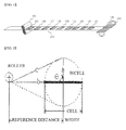
- the folding device includes a web supply unit 400 formed in the shape of a roller to supply a web 200 having plate-shaped unit cells 100, 101, 102 ... arranged at the top of a separation film at predetermined intervals and a winding jig 300 to rotate the unit cells while holding a first one of the unit cells of the web so that the unit cells are sequentially stacked in a state in which the separation film is disposed between the respective unit cells. As the winding jig 300 is rotated, the unit cells 100, 101, 102 ... are sequentially stacked.
- c may be represented by the following equation based on the change ofan angle ⁇ of the winding jig with respect to an X axis.
- FIG. 3 is a graph showing a change amount of the c value based on the angle ⁇ and a length change amount (linear change amount) of the web in a linear case.
- the graph since the angle ⁇ is rotated at uniform velocity, angular velocity is uniform, and therefore, the graph may be identical to a time-displacement graph. Consequently, the linear change amount indicates uniform velocity as a straight line having a uniform inclination.
- the rotational motion of the plate-shaped structure is not changed into a linear change amount. Consequently, it is necessary to perform compensation based on the difference between the change amount of the c value based on the angle ⁇ and the linear change amount.
- a graph of the compensation amount is also shown in FIG. 3 .
- the graph of the compensation amount has a problem in that differentiation is not possible at a point at which ⁇ is 180 degrees, and jerk is excessive at the point.
- This problem is not serious in a general production process, which is in use.
- an excessive jerk is applied to the winding device with the result that it may be necessary to frequently replace components and products may be defective.
- the rotational velocity of the winding jig is increased twice or more than that in the general production process, which is in use, to improve process efficiency, more serious problems are caused.
- the present invention has been made to solve the above problems, and other technical problems that have yet to be resolved.
- the inventors of the present application have developed a folding device to manufacture a stacked/folded type electrode assembly capable ofperiodically changing the position of a rotary shaft to compensate for the change in X-axis velocity (Vx) of a web caused during winding of plate-shaped unit cells, thereby uniformly maintaining tension of the web.
- Vx X-axis velocity
- the present inventors have discovered that in a case in which a stacked/folded type electrode assembly is manufactured using the folding device, no excessive load is applied to the device even if the rotational velocity of a winding jig, and process efficiency is improved.
- the present invention has been completed based on these findings.
- a folding device to manufacture a stacked/folded type electrode assembly having unit cells sequentially stacked in a state in which a separation film is disposed between the respective unit cells
- the folding device including a web supply unit to supply a web having plate-shaped unit cells arranged at a top of a separation film at predetermined intervals, a winding jig to rotate the unit cells while holding a first one of the unit cells of the web so that the unit cells are sequentially stacked in a state in which the separation film is disposed between the respective unit cells, and a rotary shaft compensation unit to compensate for the position of a rotary shaft of the winding jig in an advancing direction of the web (X-axis direction), wherein the rotary shaft compensation unit periodically changes the position of the rotary shaft to compensate for the change in X-axis velocity (Vx) of the web caused during winding of the plate-shaped unit cells, thereby uniformly maintaining tension of the
- Vx is velocity at the web supply unit.
- the X-axis velocity at the web supply unit must be uniform to uniformly maintain tension between the web supply unit and the winding jig.
- the compensation amount described with reference to FIGS. 2 and 3 may apparently appear as a function having a period of 180 degrees. Actually, however, a point which cannot be differentiated, i.e. a point having a different inclination value, occurs around 180 degrees. A differential value of displacement is velocity, and therefore, a point at which velocity is abruptly changed occurs. As a result, acceleration is abruptly changed as shown in FIG. 4 , resulting in the increase of a jerk.
- the unit cells are full cells or bicells.
- a full cell as a unit cell is a cell having a unit structure of cathode/separator/anode. That is, a full cell is a cell having a cathode and an anode located at opposite sides thereof.
- the full cell may have a unit structure of cathode/separator/anode/separator/cathode/separator/anode in addition to the unit structure of cathode/separator/anode.
- a bicell as a unit cell is a cell having the same electrodes located at opposite sides thereof.
- the bicell may have a unit structure of cathode/separator/anode/separator/cathode or a unit structure of anode/separator/cathode/separator/anode.
- a cell having a structure of cathode/separator/anode/separator/cathode is referred to as a 'C type bicell'
- a cell having a structure of anode/separator/cathode/separator/anode is referred to as an 'A type bicell'. That is, a cell having cathodes located at opposite sides thereof is referred to as a C type bicell, and a cell having anodes located at opposite sides thereof is referred to as an A type bicell.
- the number of cathodes, anodes, and separators constituting a bicell is not particularly restricted so long as the bicell has the same electrodes located at opposite sides thereof.
- a full cell and a bicell are manufactured by coupling a cathode and an anode in a state in which a separator is disposed between the cathode and an anode.
- a preferred example of such a coupling method is a thermal welding method.
- the cathode is prepared by applying, drying, and pressing a mixture of a cathode active material, a conductive agent, and a binder to opposite major surfaces of a cathode current collector.
- a filler may be added to the mixture as needed.
- the cathode current collector has a thickness of 3 to 500 ⁇ m.
- the cathode current collector is not particularly restricted so long as the cathode current collector exhibits high conductivity while the cathode current collector does not induce any chemical change in the battery to which it is applied.
- the cathode current collector may be made of stainless steel, aluminum, nickel, titanium or plastic carbon.
- the cathode current collector may be made of aluminum or stainless steel the surface of which is treated with carbon, nickel, titanium, or silver.
- the cathode current collector may have a micro uneven pattern formed at the surface thereof so as to increase adhesive strength of the cathode active material.
- the cathode current collector may be configured in various forms, such as a film, a sheet, a foil, a net, a porous body, a foam body, and a non-woven fabric body.
- the conductive agent is generally added so that the conductive agent has 1 to 50% by weight based on the total weight of the compound including the cathode active material.
- the conductive agent is not particularly restricted so long as the conductive agent exhibits high conductivity while the conductive agent does not induce any chemical change in the battery to which it is applied.
- graphite such as natural graphite or artificial graphite
- carbon black such as carbon black, acetylene black, Ketjen black, channel black, furnace black, lamp black, or summer black
- conductive fiber such as carbon fiber or metallic fiber
- metallic powder such as carbon fluoride powder, aluminum powder, or nickel powder
- conductive whisker such as zinc oxide or potassium titanate
- conductive metal oxide such as titanium oxide
- polyphenylene derivatives may be used as the conductive agent.
- the binder is a component assisting in binding between the active material and conductive agent and in binding with the current collector.
- the binder is generally added in an amount of 1 to 50% by weight based on the total weight of the compound including the cathode active material.
- the binder there may be used polyvinylidene fluoride, polyvinyl alcohol, carboxymethylcellulose (CMC), starch, hydroxypropylcellulose, regenerated cellulose, polyvinyl pyrollidone, tetrafluoroethylene, polyethylene, polypropylene, ethylene-propylene-diene terpolymer (EPDM), sulfonated EPDM, styrene butadiene rubber, fluoro rubber, and various copolymers.
- the filler is an optional component used to inhibit expansion of the cathode.
- the filler there is no particular limit to the filler so long as it does not cause chemical changes in the battery to which it is applied and is made of a fibrous material.
- the filler there may be used olefin polymers, such as polyethylene and polypropylene; and fibrous materials, such as glass fiber and carbon fiber.
- the anode is prepared by applying, drying and pressing an anode active material to an anode current collector.
- the conductive agent, the binder and the filler, which were previously described, may be selectively added to the anode active material as needed.
- the anode current collector has a thickness of 3 to 500 ⁇ m.
- the anode current collector is not particularly restricted so long as the anode current collector exhibits high conductivity while the anode current collector does not induce chemical changes in the battery to which it is applied.
- the anode current collector may be made of copper, stainless steel, aluminum, nickel, titanium, or plastic carbon.
- the anode current collector may be made of copper or stainless steel the surface or which is treated with carbon, nickel, titanium, or silver or an aluminum-cadmium alloy.
- the anode current collector may have a micro uneven pattern formed at the surface thereof so as to increase adhesive strength of the anode active material.
- the anode current collector may be configured in various forms, such as a film, a sheet, a foil, a net, a porous body, a foam body, and a non-woven fabric body.
- anode active material for example, there may be used carbon, such as non-graphitizing carbon or a graphite-based carbon; a metal composite oxide, such as Li x Fe 2 O 3 (0 ⁇ x ⁇ 1), Li x WO 2 (0 ⁇ x ⁇ 1), Sn x Me 1-x Me' y O z (Me: Mn, Fe, Pb, Ge; Me': Al, B, P, Si, Group 1, 2 and 3 elements of the periodic table, halogen; 0 ⁇ x ⁇ 1; 1 ⁇ y ⁇ 3; 1 ⁇ z ⁇ 8); lithium metal; lithium alloy; silicon-based alloy; tin-based alloy; metal oxide, such as SnO, SnO 2 , PbO, PbO 2 , Pb 2 O 3 , Pb 3 O 4 , Sb 2 O 3 , Sb 2 O 4 , Sb 2 O 5 , Geo, GeO 2 , Bi 2 O 3 , Bi 2 O 4 , or Bi 2 O 5 ; conductive polymer, such as polyacet
- the separator is disposed between the cathode and the anode.
- the separator for example, an insulative thin film exhibiting high ion permeability and high mechanical strength may be used.
- the separator generally has a pore diameter of 0.01 to 10 ⁇ m and a thickness of 5 to 300 ⁇ m.
- a sheet or non-woven fabric made of olefin polymer, such as polypropylene, which exhibits chemical resistance and hydrophobicity, glass fiber, or polyethylene is used.
- a solid electrolyte such as polymer
- the solid electrolyte may function as a separator.
- the separation film used in the present invention may be formed of the same material as the separator or a material different from the separator.
- the unit cells may be disposed on the separation film so that a first unit cell and a second unit cell are spaced apart from each other by a distance corresponding to at least one unit cell, and the distance between the unit cells after the second unit cell is gradually increased.
- the reason that the first unit cell and the second unit cell are spaced apart from each other is that the electrodes of the first unit cell face those of another unit cell in a state in which the outer surface of the first unit cell is fully wrapped with the separation film through one time of winding, thereby preventing the occurrence of a short circuit due to contact between the electrodes.
- electrodes at the stacked surfaces must be different from each other.
- the full cells In order to configure an electrochemical cell including secondary batteries using a plurality of full cells, the full cells must be stacked in a state in which a separation film is disposed between the respective full cells so that cathodes and anodes of the full cells face each other.
- a plurality of C type bicells and a plurality of A type bicells In order to configure an electrochemical cell including secondary batteries using a plurality of bicells, a plurality of C type bicells and a plurality of A type bicells must be stacked in a state in which a separation film is disposed between the respective full cells so that cathodes and anodes of the bicells face each other.
- the full cells may be disposed on the separation film so that the same electrodes of the first full cell 110 and the second full cell 111 face upward, and different electrodes of the full cells after the second full cell sequentially face upward.
- a positive (+) electrode of the first full cell 110 faces upward
- a positive (+) electrode of the second full cell 111 may face upward
- a negative (-) electrode of the third full cell 112 may face upward.
- positive (+) electrodes and negative (-) electrodes of the full cells may be sequentially arranged.
- the bicells may be disposed on the separation film so that the first bicell 120 and the second bicell 121 are different types of cells, and the cells after the second bicell are arranged in a pair of same type cells.
- the first bicell 120 is a C type bicell
- the second and third bicells 121 and 122 may be A type bicells
- the fourth and fifth bicells 123 and 124 may be C type bicells.
- the bicells may be sequentially arranged in a pair of same type cells.
- the shape of the winding jig is not particularly restricted so long as the winding jig is configured to wind the web.
- the winding jig may be configured to fixedly hold the web at the upper end of one of the unit cells and the lower end of the separation film corresponding to one of the unit cells.
- the winding jig winds the web in a state in which the winding jig simultaneously holds the unit cells and the separation film. Consequently, the unit cells are stacked in a state in which the separation film is disposed between the respective unit cells.
- the compensation amount of the rotary shaft based on the angle ⁇ may be changed at a period of a sine function.
- a periodic function having a displacement value most similar to that of the compensation amount graph based on theoretical calculation is a sine function.
- the displacement value of the sine function may be changed according to values of variables, such as a, b, and c, in calculating the compensation amount of the folding device, and a sine function having a displacement value similar to the calculated compensation amount may be found and used.
- the winding jig may have a rotational velocity of 20 to 200 rpm.
- the rotary shaft compensation unit of the winding jig may be used so long as compensation is performed using a periodic function.
- the rotary shaft compensation unit is configured to have an interconnected variable rotation structure to prevent separation of the rotary shaft compensation unit which may occur when the winding velocity is increased.
- a preferred example of the variable rotation structure may include a rotary eccentric roller and a variable crank to convert a rotational motion of the eccentric roller into a rectilinear motion.
- a stacked-folded type electrode assembly manufactured using the folding device with the above-stated construction. Also, a lithium secondary battery including the electrode assembly and a lithium salt-containing, non-aqueous electrolyte is provided.
- the lithium salt-containing, non-aqueous electrolyte is composed of a non-aqueous electrolyte and lithium.
- a non-aqueous electrolytic solution, solid electrolyte, or inorganic solid electrolyte may be used.
- non-protic organic solvents such as N-methyl-2-pyrollidinone, propylene carbonate, ethylene carbonate, butylene carbonate, dimethyl carbonate, diethyl carbonate, gamma-butyro lactone, 1,2-dimethoxy ethane, tetrahydroxy Franc, 2-methyl tetrahydrofuran, dimethylsulfoxide, 1,3-dioxolane, formamide, dimethylformamide, dioxolane, acetonitrile, nitromethane, methyl formate, methyl acetate, phosphoric acid triester, trimethoxy methane, dioxolane derivatives, sulfolane, methyl sulfolane, 1,3-dimethyl-2-imidazolidinone, propylene carbonate derivatives, tetrahydrofuran derivatives, ether, methyl propionate and ethyl propionate
- non-protic organic solvents such as N-methyl-2-pyrolli
- organic solid electrolyte examples include polyethylene derivatives, polyethylene oxide derivatives, polypropylene oxide derivatives, phosphoric acid ester polymers, poly agitation lysine, polyester sulfide, polyvinyl alcohols, polyvinylidene fluoride, and polymers containing ionic dissociation groups.
- inorganic solid electrolyte examples include nitrides, halides and sulphates of lithium, such as Li 3 N, LiI, Li 5 NI 2 , Li 3 N-LiI-LiOH, LiSiO 4 , LiSiO 4 -LiI-LiOH Li 2 SiS 3 , Li 4 SiO 4 , Li 4 SiO 4 -LiI-LiOH, and Li 3 PO 4 -Li 2 S-SiS 2 .
- lithium such as Li 3 N, LiI, Li 5 NI 2 , Li 3 N-LiI-LiOH, LiSiO 4 , LiSiO 4 -LiI-LiOH Li 2 SiS 3 , Li 4 SiO 4 , Li 4 SiO 4 -LiI-LiOH, and Li 3 PO 4 -Li 2 S-SiS 2 .
- the lithium salt is a material that is readily soluble in the above-mentioned non-aqueous electrolyte, and may include, for example, LiCl, LiBr, LiI, LiClO 4 , LiBF 4 , LiB 10 Cl 10 , LiPF 6 , LiCF 3 SO 3 , LiCF 3 CO 2 , LiAsF 6 , LiSbF 6 , LiAlCl 4 , CH 3 SO 3 Li; CF 3 SO 3 Li, (CF 3 SO 2 ) 2 NLi, chloroborane lithium, lower aliphatic carboxylic acid lithium, lithium tetraphenyl borate, and imide.
- pyridine triethylphosphite, triethanolamine, cyclic ether, ethylenediamine, n-glyme, hexaphosphoric triamide, nitrobenzene derivatives, sulfur, quinone imine dyes, N-substituted oxazolidinone, N,N-substituted imidazolidine, ethylene glycol dialkyl ether, ammonium salts, pyrrole, 2-methoxy ethanol, aluminum trichloride or the like may be added to the electrolyte.
- the electrolyte may further include halogen-containing solvents, such as carbon tetrachloride and ethylene trifluoride.
- the electrolyte may additionally include carbon dioxide gas.
- fluoro-ethylene carbonate (FEC) and propene sultone (PRS) may be further included.
- the secondary battery according to the present invention may be used as a battery cell used as a power source of a small-sized device.
- the secondary battery according to the present invention may be used as a unit cell of a middle or large-sized battery module including a plurality of battery cells used as a power source of a middle or large-sized device.
- a preferred example of the middle or large-sized device may be, but is not limited to, a power tool, which is operated by an electric motor, an electric four-wheeled vehicle, such as an electric vehicle (EV), a hybrid electric vehicle (HEV), or a plug-in hybrid electric vehicle (PHEV), an electric two-wheeled vehicle, such as an electric bicycle (E-bike) or an electric scooter (E-scooter), or an electric golf cart.
- an electric four-wheeled vehicle such as an electric vehicle (EV), a hybrid electric vehicle (HEV), or a plug-in hybrid electric vehicle (PHEV)
- an electric two-wheeled vehicle such as an electric bicycle (E-bike) or an electric scooter (E-scooter)
- E-scooter electric golf cart.
- FIG. 5 is a graph showing the compensation amount, the velocity, the acceleration, and the jerk based on the rotational angle ⁇ in a case in which compensation is performed using a periodic function (7.25 sine function) according to an embodiment of the present invention.
- the length change amount of the web may deviate as shown in FIG. 3 as compared with the linear change amount in which the length of the web is uniformly increased according to the rotational angle. For this reason, a method of eliminating such deviation through compensation in an X-axis direction may be considered.
- a point which cannot be differentiated occurs around 180 degrees. As a result, acceleration is abruptly changed, resulting in an excessive jerk.
- the compensation amount graph calculated in FIG. 3 is similar to a periodic function graph, i.e. a sine function graph.
- a sine function graph similar to the calculated compensation amount graph of the folding device is properly selected for compensation, therefore, differentiation is possible at every position of the compensation amount graph, and both the velocity and acceleration graphs are continuous, as shown in FIG. 5 .
- the jerk does not deviate from a predetermined range, and therefore, it is not necessary to compensate for torque due to the excessive jerk.
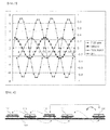
- FIG. 6 is a typical view showing an arrangement type in a case in which unit cells are full cells according to an embodiment of the present invention.
- a stacked/folded type electrode assembly may be manufactured by arranging full cells 110, 111, 112, 113, and 114, each of which has a cathode/separator/anode sequentially disposed, as unit cells, on a separation film 200 and sequentially winding the full cells 110, 111, 112, 113, and 114 from the first pull cell 110.
- the first full cell 110 and the second full cell 111 are spaced apart from each other by a distance corresponding to at least one full cell. During winding, therefore, the outer surface of the first full cell 110 is fully wrapped by the separation film 200, and then a lower end electrode (anode) of the first full cell 110 comes into contact with an upper end electrode (cathode) of the second full cell 111.
- the length of the separation film 200 to wrap the full cells 112, 113, and 114 after the second full cell 111 is increased during sequential stacking performed by winding. For this reason, the full cells are disposed so that the distance therebetween is sequentially increased in the winding direction.
- the full cells 110, 111, 112, 113, and 114 are configured so that cathodes and anodes face each other at the interface between the stacked full cells during winding.
- the first full cell 110 and the second full cell 111 are full cells each having a cathode as an upper end electrode
- the third full cell 112 is a full cell having an anode as an upper end electrode
- the fourth full cell 113 is a full cell having a cathode as an upper end electrode
- the fifth full cell 114 is a full cell having an anode as an upper end electrode.
- the full cells 111 and 113 each of which having a cathode as an upper end electrode
- the full cells 112 and 114 each of which having an anode as an upper end electrode, are alternately arranged except for the first full cell 110.
- FIG. 7 is a typical view showing an arrangement type in a case in which unit cells are bicells according to another embodiment of the present invention.
- bicells 120, 121, 122, 123, and 124 each of which has a cathode/separator/anode/separator/cathode or anode/separator/cathode/separator/anode sequentially disposed, as unit cells, are disposed on a separation film 200, and the bicells 120, 121, 122, 123, and 124 are sequentially wound from the first bicell 120 to manufacture a stacked/folded type electrode assembly.
- the first bicell 120 and the second bicell 121 are spaced apart from each other by a distance corresponding to at least one bicell. During winding, therefore, the outer surface of the first bicell 120 is fully wrapped by the separation film 200, and then a lower end electrode (anode) of the first bicell 120 comes into contact with an upper end electrode (cathode) of the second bicell 121.
- the length of the separation film 200 to wrap the bicells 122, 123, and 124 after the second bicell 121 is increased during sequential stacking performed by winding. For this reason, the bicells are disposed so that the distance therebetween is sequentially increased in the winding direction.
- the bicells 120, 121, 122, 123, and 124 are configured so that cathodes and anodes face each other at the interface between the stacked bicells during winding.
- the first bicell 120 has an anode as an external electrode
- the second bicell 121 and the third bicell 122 have a cathode as an external electrode
- the fourth bicell 123 and the fifth bicell 124 have an anode as an external electrode. That is, the bicells 121 and 122 having a cathode as an external electrode and the bicells 123 and 124 having an anode as an external electrode are alternately arranged every two bicells except for the first bicell 120.
- FIG. 8 is a schematic typical view showing a folding device according to an embodiment of the present invention.
- a folding device 500 includes a rotary shaft compensation unit and a winding unit.
- the rotary shaft compensation unit is configured to have an interconnected variable rotation structure.
- the rotary shaft compensation unit includes a rotary eccentric roller 510 and a variable crank 520 to convert a rotational motion of the eccentric roller 510 into a rectilinear motion.
- variable crank 520 At a portion of the variable crank 520 with which an eccentric shaft of the eccentric roller 510 engages is formed a groove extending in the vertical direction by a rotational diameter of the eccentric shaft.
- the variable crank 520 is configured so that the movement of the variable crank 520 in the vertical direction is restrained.
- the rotational motion transmitted through the eccentric roller 510 does not move the variable crank 520 in the vertical direction but is converted into a horizontal rectilinear motion through the groove.
- This rectilinear motion is performed by rotation of the eccentric shaft of the eccentric roller 510. Consequently, the rectilinear motion is performed in the form of a periodic function.
- variable crank 520 of the rotary shaft compensation unit is operatively connected to the winding unit 530 having a winding jig 540 mounted thereto to compensate for a rotary shaft of the winding jig 540 in the advancing direction of the web.
- feeding velocity of a web having unit cells 550 arranged on a separation film 560 during winding the web using the winding jig 540 is uniformly maintained. Also, in a case in which the variable crank is used as described above, it is possible to prevent separation of the folding device which may occur when the variable crank is moved at high velocity.
- a folding device to manufacture a stacked/folded type electrode assembly according to the present invention is configured so that rotational velocity of the folding device can be increased without change of a conventional device, thereby improving process efficiency.
Landscapes
- Engineering & Computer Science (AREA)
- Manufacturing & Machinery (AREA)
- Chemical & Material Sciences (AREA)
- Chemical Kinetics & Catalysis (AREA)
- Electrochemistry (AREA)
- General Chemical & Material Sciences (AREA)
- Secondary Cells (AREA)
Applications Claiming Priority (2)
| Application Number | Priority Date | Filing Date | Title |
|---|---|---|---|
| KR20100067728 | 2010-07-14 | ||
| PCT/KR2011/005129 WO2012008742A2 (ko) | 2010-07-14 | 2011-07-13 | 전극조립체의 폴딩 장치 |
Publications (3)
| Publication Number | Publication Date |
|---|---|
| EP2595232A2 true EP2595232A2 (de) | 2013-05-22 |
| EP2595232A4 EP2595232A4 (de) | 2014-07-30 |
| EP2595232B1 EP2595232B1 (de) | 2018-01-31 |
Family
ID=45469917
Family Applications (1)
| Application Number | Title | Priority Date | Filing Date |
|---|---|---|---|
| EP11807027.5A Active EP2595232B1 (de) | 2010-07-14 | 2011-07-13 | Faltvorrichtung für eine elektrodenanordnung |
Country Status (6)
| Country | Link |
|---|---|
| US (1) | US9455467B2 (de) |
| EP (1) | EP2595232B1 (de) |
| JP (1) | JP5769807B2 (de) |
| KR (2) | KR101315130B1 (de) |
| CN (1) | CN102986079B (de) |
| WO (1) | WO2012008742A2 (de) |
Cited By (2)
| Publication number | Priority date | Publication date | Assignee | Title |
|---|---|---|---|---|
| EP2808933A4 (de) * | 2012-05-23 | 2015-07-15 | Lg Chemical Ltd | Verfahren zur herstellung einer elektrodenanordnung und elektrochemische vorrichtung mit der elektrodenanordnung |
| CN111628226A (zh) * | 2020-06-01 | 2020-09-04 | 蜂巢能源科技有限公司 | 叠片工艺方法和叠片装置 |
Families Citing this family (9)
| Publication number | Priority date | Publication date | Assignee | Title |
|---|---|---|---|---|
| KR101315130B1 (ko) | 2010-07-14 | 2013-10-07 | 주식회사 엘지화학 | 전극조립체의 폴딩 장치 |
| JP5689175B2 (ja) * | 2010-07-14 | 2015-03-25 | エルジー・ケム・リミテッド | 電極アセンブリのための折り畳み装置 |
| KR101480742B1 (ko) * | 2012-03-02 | 2015-01-09 | 주식회사 엘지화학 | 전극조립체의 폴딩 장치 |
| KR101484525B1 (ko) * | 2012-05-07 | 2015-01-20 | 주식회사 엘지화학 | 전극 적층체 및 이를 포함하는 리튬 이차전지 |
| KR101500520B1 (ko) * | 2012-05-11 | 2015-03-09 | 주식회사 엘지화학 | 전극조립체의 폴딩 장치 |
| KR101619604B1 (ko) | 2013-09-26 | 2016-05-10 | 주식회사 엘지화학 | 전극조립체 및 이차전지의 제조방법 |
| KR102065338B1 (ko) * | 2016-12-07 | 2020-02-11 | 주식회사 엘지화학 | 전극조립체 제조를 위한 폴딩 장치 및 스택/폴딩형 전극조립체의 제조방법 |
| EP3634896B1 (de) * | 2017-06-07 | 2021-08-11 | Oerlikon Textile GmbH & Co. KG | Verfahren und vorrichtung zur überwachung einer fadenspannung an einem laufenden faden |
| KR102851359B1 (ko) * | 2021-09-29 | 2025-08-26 | 주식회사 엘지에너지솔루션 | 전극조립체 제조방법 및 이의 제조장치 |
Family Cites Families (26)
| Publication number | Priority date | Publication date | Assignee | Title |
|---|---|---|---|---|
| JPS5453254A (en) * | 1977-10-04 | 1979-04-26 | Chukyo Electric Co | Method of takinggup condenser element and device therefor |
| JPH06168736A (ja) | 1992-11-30 | 1994-06-14 | Sanyo Electric Co Ltd | 渦巻電極体の製造方法 |
| JPH07285717A (ja) | 1994-04-14 | 1995-10-31 | Sony Corp | 帯状材巻取装置 |
| JPH11242956A (ja) * | 1998-02-25 | 1999-09-07 | Fujitsu Ltd | 電池用電極体の製造方法 |
| JP4161400B2 (ja) | 1998-03-31 | 2008-10-08 | 宇部興産株式会社 | 非水電解質リチウム二次電池およびその製造方法 |
| JP3228907B2 (ja) * | 1998-06-25 | 2001-11-12 | 日本特殊陶業株式会社 | リチウムイオンポリマー型2次電池の製造方法 |
| JP4482965B2 (ja) | 1999-08-17 | 2010-06-16 | ソニー株式会社 | 巻取装置および巻取方法 |
| KR200182060Y1 (ko) | 1999-12-09 | 2000-05-15 | 박광길 | 와이셔츠 |
| KR200182059Y1 (ko) | 1999-12-09 | 2000-05-15 | 노대구 | 발가락 속 양말 |
| KR200182058Y1 (ko) | 1999-12-09 | 2000-05-15 | 강윤모 | 음료수 용기의 밀봉용 마개 |
| KR100515571B1 (ko) | 2000-02-08 | 2005-09-20 | 주식회사 엘지화학 | 중첩 전기 화학 셀 |
| KR100497147B1 (ko) * | 2000-02-08 | 2005-06-29 | 주식회사 엘지화학 | 다중 중첩 전기화학 셀 및 그의 제조방법 |
| KR100515572B1 (ko) * | 2000-02-08 | 2005-09-20 | 주식회사 엘지화학 | 중첩 전기화학 셀 및 그의 제조 방법 |
| JP3726623B2 (ja) | 2000-02-29 | 2005-12-14 | 三菱電機株式会社 | 巻き取り装置および巻き取り方法 |
| JP2003146538A (ja) * | 2001-11-15 | 2003-05-21 | Sony Corp | 巻取方法および巻取装置 |
| FR2849283B1 (fr) * | 2002-12-23 | 2005-10-28 | Batscap Sa | Architecture de dispositif de bobinage d'ensemble de stockage d'energie electrique |
| CN2746555Y (zh) * | 2004-11-30 | 2005-12-14 | 比亚迪股份有限公司 | 锂离子电池极芯卷绕针 |
| KR100933427B1 (ko) * | 2005-08-16 | 2009-12-23 | 주식회사 엘지화학 | 교차분리막으로 이루어진 전기화학소자 |
| KR100709861B1 (ko) * | 2005-12-23 | 2007-04-23 | 삼성에스디아이 주식회사 | 전극롤 권취용 맨드릴 |
| KR100859996B1 (ko) | 2006-05-15 | 2008-09-25 | 주식회사 엘지화학 | 이중 권취형 전극조립체 |
| KR100861705B1 (ko) | 2006-05-29 | 2008-10-06 | 주식회사 엘지화학 | 구조적 안정성과 전해액의 젖음성이 우수한 전극조립체 및이를 포함하는 이차전지 |
| KR100987300B1 (ko) | 2007-07-04 | 2010-10-12 | 주식회사 엘지화학 | 스택-폴딩형 전극조립체 및 그것의 제조방법 |
| KR101014817B1 (ko) * | 2007-12-14 | 2011-02-14 | 주식회사 엘지화학 | 안전 부재를 포함하고 있는 스택/폴딩형 전극조립체 및그것의 제조방법 |
| CN101719561B (zh) * | 2009-11-24 | 2011-12-28 | 深圳市吉阳自动化科技有限公司 | 一种卷绕装置及卷绕方法 |
| JP5689175B2 (ja) | 2010-07-14 | 2015-03-25 | エルジー・ケム・リミテッド | 電極アセンブリのための折り畳み装置 |
| KR101315130B1 (ko) | 2010-07-14 | 2013-10-07 | 주식회사 엘지화학 | 전극조립체의 폴딩 장치 |
-
2011
- 2011-07-13 KR KR1020110069362A patent/KR101315130B1/ko active Active
- 2011-07-13 US US13/809,416 patent/US9455467B2/en active Active
- 2011-07-13 WO PCT/KR2011/005129 patent/WO2012008742A2/ko not_active Ceased
- 2011-07-13 CN CN201180034342.XA patent/CN102986079B/zh active Active
- 2011-07-13 JP JP2013519585A patent/JP5769807B2/ja active Active
- 2011-07-13 EP EP11807027.5A patent/EP2595232B1/de active Active
-
2013
- 2013-09-17 KR KR1020130111535A patent/KR101428033B1/ko active Active
Cited By (4)
| Publication number | Priority date | Publication date | Assignee | Title |
|---|---|---|---|---|
| EP2808933A4 (de) * | 2012-05-23 | 2015-07-15 | Lg Chemical Ltd | Verfahren zur herstellung einer elektrodenanordnung und elektrochemische vorrichtung mit der elektrodenanordnung |
| EP3671929A1 (de) * | 2012-05-23 | 2020-06-24 | LG Chem, Ltd. | Herstellungsverfahren einer elektrodenanordnung und elektrochemische zelle damit |
| EP3961780A1 (de) * | 2012-05-23 | 2022-03-02 | LG Chem, Ltd. | Herstellungsverfahren einer elektrodenanordnung und elektrochemische zelle damit |
| CN111628226A (zh) * | 2020-06-01 | 2020-09-04 | 蜂巢能源科技有限公司 | 叠片工艺方法和叠片装置 |
Also Published As
| Publication number | Publication date |
|---|---|
| CN102986079B (zh) | 2016-09-21 |
| EP2595232B1 (de) | 2018-01-31 |
| WO2012008742A3 (ko) | 2012-05-03 |
| US9455467B2 (en) | 2016-09-27 |
| KR101315130B1 (ko) | 2013-10-07 |
| JP2013532367A (ja) | 2013-08-15 |
| KR20120007458A (ko) | 2012-01-20 |
| JP5769807B2 (ja) | 2015-08-26 |
| WO2012008742A2 (ko) | 2012-01-19 |
| US20130209848A1 (en) | 2013-08-15 |
| CN102986079A (zh) | 2013-03-20 |
| KR20130110135A (ko) | 2013-10-08 |
| KR101428033B1 (ko) | 2014-08-06 |
| EP2595232A4 (de) | 2014-07-30 |
Similar Documents
| Publication | Publication Date | Title |
|---|---|---|
| EP2595233B1 (de) | Faltvorrichtung für eine elektrodenanordnung | |
| EP2595232B1 (de) | Faltvorrichtung für eine elektrodenanordnung | |
| US8383262B2 (en) | Stacking-type secondary battery providing two or more operation voltages | |
| US9780359B2 (en) | Method of manufacturing electrode for lithium secondary battery and electrode manufactured using the same | |
| EP3432404B1 (de) | Verfahren zur herstellung einer stapel-/faltelektrodenanordnung | |
| KR102096817B1 (ko) | 노칭부를 포함하는 전극 시트를 이용하여 전극판을 제조하는 방법 | |
| EP2922135B1 (de) | Batteriezelle mit amorpher struktur | |
| EP3196970B1 (de) | Verfahren zur herstellung einer lithiumsekundärbatterie und damit hergestellte lithiumsekundärbatterie | |
| KR101490845B1 (ko) | 전극조립체의 제조를 위한 폴딩 장치 | |
| KR102011679B1 (ko) | 양면에 활물질의 로딩량이 상이한 전극판을 포함하는 전극조립체 | |
| KR102026292B1 (ko) | 활물질 로딩량의 구배를 가진 전극을 포함하는 전극조립체 | |
| EP3370281B1 (de) | Elektrode mit elektrodenstromkollektor einer dreidimensionalen netzwerkstruktur | |
| KR102082467B1 (ko) | 집전체 중심 부위에 높은 활물질 로딩량을 가지는 전극을 포함하는 전극조립체 | |
| KR102025564B1 (ko) | 전지 소자들 사이에 개재되어 있는 단위셀을 포함하는 전극조립체 | |
| KR101500520B1 (ko) | 전극조립체의 폴딩 장치 | |
| KR101480742B1 (ko) | 전극조립체의 폴딩 장치 |
Legal Events
| Date | Code | Title | Description |
|---|---|---|---|
| PUAI | Public reference made under article 153(3) epc to a published international application that has entered the european phase |
Free format text: ORIGINAL CODE: 0009012 |
|
| 17P | Request for examination filed |
Effective date: 20130109 |
|
| AK | Designated contracting states |
Kind code of ref document: A2 Designated state(s): AL AT BE BG CH CY CZ DE DK EE ES FI FR GB GR HR HU IE IS IT LI LT LU LV MC MK MT NL NO PL PT RO RS SE SI SK SM TR |
|
| DAX | Request for extension of the european patent (deleted) | ||
| A4 | Supplementary search report drawn up and despatched |
Effective date: 20140630 |
|
| RIC1 | Information provided on ipc code assigned before grant |
Ipc: B65H 23/195 20060101ALI20140624BHEP Ipc: H01M 10/0525 20100101ALI20140624BHEP Ipc: H01M 10/0585 20100101ALI20140624BHEP Ipc: H01M 10/04 20060101AFI20140624BHEP |
|
| 17Q | First examination report despatched |
Effective date: 20150226 |
|
| GRAP | Despatch of communication of intention to grant a patent |
Free format text: ORIGINAL CODE: EPIDOSNIGR1 |
|
| RIC1 | Information provided on ipc code assigned before grant |
Ipc: H01M 10/0525 20100101ALN20171030BHEP Ipc: H01M 10/0583 20100101ALN20171030BHEP Ipc: H01M 10/04 20060101AFI20171030BHEP |
|
| INTG | Intention to grant announced |
Effective date: 20171117 |
|
| GRAS | Grant fee paid |
Free format text: ORIGINAL CODE: EPIDOSNIGR3 |
|
| GRAA | (expected) grant |
Free format text: ORIGINAL CODE: 0009210 |
|
| AK | Designated contracting states |
Kind code of ref document: B1 Designated state(s): AL AT BE BG CH CY CZ DE DK EE ES FI FR GB GR HR HU IE IS IT LI LT LU LV MC MK MT NL NO PL PT RO RS SE SI SK SM TR |
|
| REG | Reference to a national code |
Ref country code: GB Ref legal event code: FG4D Ref country code: CH Ref legal event code: EP |
|
| REG | Reference to a national code |
Ref country code: AT Ref legal event code: REF Ref document number: 968131 Country of ref document: AT Kind code of ref document: T Effective date: 20180215 |
|
| REG | Reference to a national code |
Ref country code: IE Ref legal event code: FG4D |
|
| REG | Reference to a national code |
Ref country code: DE Ref legal event code: R096 Ref document number: 602011045466 Country of ref document: DE |
|
| REG | Reference to a national code |
Ref country code: NL Ref legal event code: MP Effective date: 20180131 |
|
| REG | Reference to a national code |
Ref country code: LT Ref legal event code: MG4D |
|
| REG | Reference to a national code |
Ref country code: AT Ref legal event code: MK05 Ref document number: 968131 Country of ref document: AT Kind code of ref document: T Effective date: 20180131 |
|
| REG | Reference to a national code |
Ref country code: FR Ref legal event code: PLFP Year of fee payment: 8 |
|
| PG25 | Lapsed in a contracting state [announced via postgrant information from national office to epo] |
Ref country code: NO Free format text: LAPSE BECAUSE OF FAILURE TO SUBMIT A TRANSLATION OF THE DESCRIPTION OR TO PAY THE FEE WITHIN THE PRESCRIBED TIME-LIMIT Effective date: 20180430 Ref country code: ES Free format text: LAPSE BECAUSE OF FAILURE TO SUBMIT A TRANSLATION OF THE DESCRIPTION OR TO PAY THE FEE WITHIN THE PRESCRIBED TIME-LIMIT Effective date: 20180131 Ref country code: NL Free format text: LAPSE BECAUSE OF FAILURE TO SUBMIT A TRANSLATION OF THE DESCRIPTION OR TO PAY THE FEE WITHIN THE PRESCRIBED TIME-LIMIT Effective date: 20180131 Ref country code: LT Free format text: LAPSE BECAUSE OF FAILURE TO SUBMIT A TRANSLATION OF THE DESCRIPTION OR TO PAY THE FEE WITHIN THE PRESCRIBED TIME-LIMIT Effective date: 20180131 Ref country code: HR Free format text: LAPSE BECAUSE OF FAILURE TO SUBMIT A TRANSLATION OF THE DESCRIPTION OR TO PAY THE FEE WITHIN THE PRESCRIBED TIME-LIMIT Effective date: 20180131 Ref country code: FI Free format text: LAPSE BECAUSE OF FAILURE TO SUBMIT A TRANSLATION OF THE DESCRIPTION OR TO PAY THE FEE WITHIN THE PRESCRIBED TIME-LIMIT Effective date: 20180131 |
|
| PG25 | Lapsed in a contracting state [announced via postgrant information from national office to epo] |
Ref country code: IS Free format text: LAPSE BECAUSE OF FAILURE TO SUBMIT A TRANSLATION OF THE DESCRIPTION OR TO PAY THE FEE WITHIN THE PRESCRIBED TIME-LIMIT Effective date: 20180531 Ref country code: GR Free format text: LAPSE BECAUSE OF FAILURE TO SUBMIT A TRANSLATION OF THE DESCRIPTION OR TO PAY THE FEE WITHIN THE PRESCRIBED TIME-LIMIT Effective date: 20180501 Ref country code: AT Free format text: LAPSE BECAUSE OF FAILURE TO SUBMIT A TRANSLATION OF THE DESCRIPTION OR TO PAY THE FEE WITHIN THE PRESCRIBED TIME-LIMIT Effective date: 20180131 Ref country code: LV Free format text: LAPSE BECAUSE OF FAILURE TO SUBMIT A TRANSLATION OF THE DESCRIPTION OR TO PAY THE FEE WITHIN THE PRESCRIBED TIME-LIMIT Effective date: 20180131 Ref country code: SE Free format text: LAPSE BECAUSE OF FAILURE TO SUBMIT A TRANSLATION OF THE DESCRIPTION OR TO PAY THE FEE WITHIN THE PRESCRIBED TIME-LIMIT Effective date: 20180131 Ref country code: PL Free format text: LAPSE BECAUSE OF FAILURE TO SUBMIT A TRANSLATION OF THE DESCRIPTION OR TO PAY THE FEE WITHIN THE PRESCRIBED TIME-LIMIT Effective date: 20180131 Ref country code: BG Free format text: LAPSE BECAUSE OF FAILURE TO SUBMIT A TRANSLATION OF THE DESCRIPTION OR TO PAY THE FEE WITHIN THE PRESCRIBED TIME-LIMIT Effective date: 20180430 Ref country code: RS Free format text: LAPSE BECAUSE OF FAILURE TO SUBMIT A TRANSLATION OF THE DESCRIPTION OR TO PAY THE FEE WITHIN THE PRESCRIBED TIME-LIMIT Effective date: 20180131 |
|
| RAP2 | Party data changed (patent owner data changed or rights of a patent transferred) |
Owner name: LG CHEM, LTD. |
|
| PG25 | Lapsed in a contracting state [announced via postgrant information from national office to epo] |
Ref country code: AL Free format text: LAPSE BECAUSE OF FAILURE TO SUBMIT A TRANSLATION OF THE DESCRIPTION OR TO PAY THE FEE WITHIN THE PRESCRIBED TIME-LIMIT Effective date: 20180131 Ref country code: RO Free format text: LAPSE BECAUSE OF FAILURE TO SUBMIT A TRANSLATION OF THE DESCRIPTION OR TO PAY THE FEE WITHIN THE PRESCRIBED TIME-LIMIT Effective date: 20180131 Ref country code: IT Free format text: LAPSE BECAUSE OF FAILURE TO SUBMIT A TRANSLATION OF THE DESCRIPTION OR TO PAY THE FEE WITHIN THE PRESCRIBED TIME-LIMIT Effective date: 20180131 Ref country code: EE Free format text: LAPSE BECAUSE OF FAILURE TO SUBMIT A TRANSLATION OF THE DESCRIPTION OR TO PAY THE FEE WITHIN THE PRESCRIBED TIME-LIMIT Effective date: 20180131 |
|
| REG | Reference to a national code |
Ref country code: DE Ref legal event code: R097 Ref document number: 602011045466 Country of ref document: DE |
|
| PG25 | Lapsed in a contracting state [announced via postgrant information from national office to epo] |
Ref country code: DK Free format text: LAPSE BECAUSE OF FAILURE TO SUBMIT A TRANSLATION OF THE DESCRIPTION OR TO PAY THE FEE WITHIN THE PRESCRIBED TIME-LIMIT Effective date: 20180131 Ref country code: CZ Free format text: LAPSE BECAUSE OF FAILURE TO SUBMIT A TRANSLATION OF THE DESCRIPTION OR TO PAY THE FEE WITHIN THE PRESCRIBED TIME-LIMIT Effective date: 20180131 Ref country code: SM Free format text: LAPSE BECAUSE OF FAILURE TO SUBMIT A TRANSLATION OF THE DESCRIPTION OR TO PAY THE FEE WITHIN THE PRESCRIBED TIME-LIMIT Effective date: 20180131 Ref country code: SK Free format text: LAPSE BECAUSE OF FAILURE TO SUBMIT A TRANSLATION OF THE DESCRIPTION OR TO PAY THE FEE WITHIN THE PRESCRIBED TIME-LIMIT Effective date: 20180131 |
|
| PLBE | No opposition filed within time limit |
Free format text: ORIGINAL CODE: 0009261 |
|
| STAA | Information on the status of an ep patent application or granted ep patent |
Free format text: STATUS: NO OPPOSITION FILED WITHIN TIME LIMIT |
|
| 26N | No opposition filed |
Effective date: 20181102 |
|
| PG25 | Lapsed in a contracting state [announced via postgrant information from national office to epo] |
Ref country code: SI Free format text: LAPSE BECAUSE OF FAILURE TO SUBMIT A TRANSLATION OF THE DESCRIPTION OR TO PAY THE FEE WITHIN THE PRESCRIBED TIME-LIMIT Effective date: 20180131 |
|
| REG | Reference to a national code |
Ref country code: CH Ref legal event code: PL |
|
| PG25 | Lapsed in a contracting state [announced via postgrant information from national office to epo] |
Ref country code: LU Free format text: LAPSE BECAUSE OF NON-PAYMENT OF DUE FEES Effective date: 20180713 Ref country code: MC Free format text: LAPSE BECAUSE OF FAILURE TO SUBMIT A TRANSLATION OF THE DESCRIPTION OR TO PAY THE FEE WITHIN THE PRESCRIBED TIME-LIMIT Effective date: 20180131 |
|
| REG | Reference to a national code |
Ref country code: BE Ref legal event code: MM Effective date: 20180731 |
|
| REG | Reference to a national code |
Ref country code: IE Ref legal event code: MM4A |
|
| PG25 | Lapsed in a contracting state [announced via postgrant information from national office to epo] |
Ref country code: IE Free format text: LAPSE BECAUSE OF NON-PAYMENT OF DUE FEES Effective date: 20180713 Ref country code: LI Free format text: LAPSE BECAUSE OF NON-PAYMENT OF DUE FEES Effective date: 20180731 Ref country code: CH Free format text: LAPSE BECAUSE OF NON-PAYMENT OF DUE FEES Effective date: 20180731 |
|
| PG25 | Lapsed in a contracting state [announced via postgrant information from national office to epo] |
Ref country code: BE Free format text: LAPSE BECAUSE OF NON-PAYMENT OF DUE FEES Effective date: 20180731 |
|
| PG25 | Lapsed in a contracting state [announced via postgrant information from national office to epo] |
Ref country code: MT Free format text: LAPSE BECAUSE OF NON-PAYMENT OF DUE FEES Effective date: 20180713 |
|
| PG25 | Lapsed in a contracting state [announced via postgrant information from national office to epo] |
Ref country code: TR Free format text: LAPSE BECAUSE OF FAILURE TO SUBMIT A TRANSLATION OF THE DESCRIPTION OR TO PAY THE FEE WITHIN THE PRESCRIBED TIME-LIMIT Effective date: 20180131 |
|
| PG25 | Lapsed in a contracting state [announced via postgrant information from national office to epo] |
Ref country code: HU Free format text: LAPSE BECAUSE OF FAILURE TO SUBMIT A TRANSLATION OF THE DESCRIPTION OR TO PAY THE FEE WITHIN THE PRESCRIBED TIME-LIMIT; INVALID AB INITIO Effective date: 20110713 Ref country code: PT Free format text: LAPSE BECAUSE OF FAILURE TO SUBMIT A TRANSLATION OF THE DESCRIPTION OR TO PAY THE FEE WITHIN THE PRESCRIBED TIME-LIMIT Effective date: 20180131 |
|
| PG25 | Lapsed in a contracting state [announced via postgrant information from national office to epo] |
Ref country code: MK Free format text: LAPSE BECAUSE OF NON-PAYMENT OF DUE FEES Effective date: 20180131 Ref country code: CY Free format text: LAPSE BECAUSE OF FAILURE TO SUBMIT A TRANSLATION OF THE DESCRIPTION OR TO PAY THE FEE WITHIN THE PRESCRIBED TIME-LIMIT Effective date: 20180131 |
|
| P01 | Opt-out of the competence of the unified patent court (upc) registered |
Effective date: 20230408 |
|
| REG | Reference to a national code |
Ref country code: DE Ref legal event code: R081 Ref document number: 602011045466 Country of ref document: DE Owner name: LG ENERGY SOLUTION, LTD., KR Free format text: FORMER OWNER: LG CHEM, LTD., SEOUL, KR |
|
| REG | Reference to a national code |
Ref country code: GB Ref legal event code: 732E Free format text: REGISTERED BETWEEN 20230824 AND 20230831 |
|
| PGFP | Annual fee paid to national office [announced via postgrant information from national office to epo] |
Ref country code: GB Payment date: 20250624 Year of fee payment: 15 |
|
| PGFP | Annual fee paid to national office [announced via postgrant information from national office to epo] |
Ref country code: FR Payment date: 20250624 Year of fee payment: 15 |
|
| PGFP | Annual fee paid to national office [announced via postgrant information from national office to epo] |
Ref country code: DE Payment date: 20250624 Year of fee payment: 15 |