EP2593333B1 - Fahrzeug in modularer bauweise - Google Patents
Fahrzeug in modularer bauweise Download PDFInfo
- Publication number
- EP2593333B1 EP2593333B1 EP11703654.1A EP11703654A EP2593333B1 EP 2593333 B1 EP2593333 B1 EP 2593333B1 EP 11703654 A EP11703654 A EP 11703654A EP 2593333 B1 EP2593333 B1 EP 2593333B1
- Authority
- EP
- European Patent Office
- Prior art keywords
- chassis
- trailer
- vehicle
- semi
- vehicle according
- Prior art date
- Legal status (The legal status is an assumption and is not a legal conclusion. Google has not performed a legal analysis and makes no representation as to the accuracy of the status listed.)
- Active
Links
- 238000007789 sealing Methods 0.000 claims description 13
- 230000008859 change Effects 0.000 claims description 10
- 230000001105 regulatory effect Effects 0.000 claims description 7
- 230000001276 controlling effect Effects 0.000 claims description 4
- 238000010276 construction Methods 0.000 claims description 2
- 238000010168 coupling process Methods 0.000 description 20
- 230000008878 coupling Effects 0.000 description 17
- 238000005859 coupling reaction Methods 0.000 description 17
- 238000011161 development Methods 0.000 description 13
- 230000018109 developmental process Effects 0.000 description 13
- 239000000725 suspension Substances 0.000 description 12
- 241000272165 Charadriidae Species 0.000 description 5
- 230000008901 benefit Effects 0.000 description 5
- 230000005540 biological transmission Effects 0.000 description 3
- 230000007246 mechanism Effects 0.000 description 3
- 230000007704 transition Effects 0.000 description 3
- 238000006073 displacement reaction Methods 0.000 description 2
- 230000009975 flexible effect Effects 0.000 description 2
- 230000010354 integration Effects 0.000 description 2
- 239000000758 substrate Substances 0.000 description 2
- 238000010521 absorption reaction Methods 0.000 description 1
- 230000006978 adaptation Effects 0.000 description 1
- 239000002131 composite material Substances 0.000 description 1
- 230000002950 deficient Effects 0.000 description 1
- 230000001419 dependent effect Effects 0.000 description 1
- 239000002184 metal Substances 0.000 description 1
- 238000000034 method Methods 0.000 description 1
- 238000003032 molecular docking Methods 0.000 description 1
- NJPPVKZQTLUDBO-UHFFFAOYSA-N novaluron Chemical compound C1=C(Cl)C(OC(F)(F)C(OC(F)(F)F)F)=CC=C1NC(=O)NC(=O)C1=C(F)C=CC=C1F NJPPVKZQTLUDBO-UHFFFAOYSA-N 0.000 description 1
- 230000035515 penetration Effects 0.000 description 1
- 230000008569 process Effects 0.000 description 1
- 230000009467 reduction Effects 0.000 description 1
Images


Classifications
-
- B—PERFORMING OPERATIONS; TRANSPORTING
- B60—VEHICLES IN GENERAL
- B60P—VEHICLES ADAPTED FOR LOAD TRANSPORTATION OR TO TRANSPORT, TO CARRY, OR TO COMPRISE SPECIAL LOADS OR OBJECTS
- B60P3/00—Vehicles adapted to transport, to carry or to comprise special loads or objects
- B60P3/32—Vehicles adapted to transport, to carry or to comprise special loads or objects comprising living accommodation for people, e.g. caravans, camping, or like vehicles
Definitions
- the present invention relates to a vehicle of modular construction, namely with a chassis and a semitrailer which is completely detachable from the chassis, wherein the semitrailer comprises at least one functional unit.
- Such vehicles come in different areas, for example in the field of supply or transport industry, but especially in the military, are used.
- Individual vehicles or functional arrangements formed from two or more such vehicles can for example be assembled and used as a mobile hospital, as a canteen, as a warehouse, as a conference room or as a command post.
- the chassis or chassis of such described by the features of the preamble of claim 1 special wide-body vehicles comprises in a known manner, the suspension and the usual drive elements, such as transmission, engine and the like.
- the semitrailer is formed in the manner described from the driver's cab and an additional functional unit, so for example the operating room, the hospital, the conference area or the like.
- the cab and the functional unit form a unit that can be attached to the chassis.
- the functional unit, the driver's cab or the semi-trailer is completely off the chassis solvable.
- completely solvable is meant in particular that the functional unit, the driver's cab or the semi-trailer can be replaced, so a chassis can be equipped with changing functional units, cabs or semi-trailer.
- this also means that at least part of the steering of the vehicle is located within the cab, which is modularly separate from the chassis, for which reason the steering is preferably designed electrically.
- the invention is therefore an object of the invention to provide a vehicle that can be coupled exactly and safely in any orientation to other vehicles, especially for larger bumps in the ground.
- the vehicle is associated with a device which is designed and adapted for changing the position of the trailer relative to the chassis.
- the vehicle is associated with a device which is designed and adapted for changing the position of the trailer relative to the chassis.
- this embodiment of the invention it is possible in a particularly simple and secure way to change the position of the trailer independently of the chassis individually to compensate for unevenness in the ground and on the other hand, the position of the semi-trailer relative to the chassis for optimal coupling of two or more vehicles or the To change semitrailers. This can compensate for uneven floors and the trailer can be aligned horizontally. Furthermore, the position of the trailer in the horizontal is arbitrarily changeable. For coupling two or more vehicles, the semitrailers can be moved horizontally to bring them as close to each other as possible.
- the device comprises an adjusting unit for the horizontal adjustment of the position of the trailer to the chassis with guides and drive means. This makes it possible to move the semi-trailer as close as possible to each other and safely coupled together to form a functional arrangement.
- the invention is characterized in that the adjusting unit comprises at least two guides which are arranged orthogonal to each other, wherein each guide is associated with at least one drive means.
- each guide is associated with at least one drive means.
- An expedient embodiment of the invention is characterized in that the chassis has a chassis subassembly which is designed and arranged for vertical alignment of the chassis relative to a base.
- the type of functional unit may necessitate vertical alignment of the chassis, semi-trailer and / or vehicle.
- the chassis is vertically aligned such that the functional unit does not fall off to one side or, in other words, is in the scale.
- the chassis lifting device can raise the chassis on the sloping side of the ground so that the chassis reaches the desired position.
- Chassis are aligned vertically relative to the ground.
- the chassis lifting device has a downwardly pivotable and lockable lifting means.
- the lifting means may for example be a hydraulic cylinder. But the lifting means may also be a translational and / or rotary, preferably telescopically adjustable pneumatic, hydraulic and / or motor unit. Other common lifting means can also be used.
- For pivoting one end of the lifting means can be rotatably mounted connected to the chassis.
- This storage can also be designed for locking and / or configured.
- Other common locking means for locking the lifting means are also used.
- the chassis lifting device has four lifting means. However, the chassis lifting device may also have more or less than four lifting means.
- the chassis lifting device is a hydraulic device and is designed and set up exclusively for vertical alignment of the chassis relative to the ground.
- the hydraulic device can only serve for vertical adjustment and / or alignment of the chassis. Since the semi-trailer is connected to the chassis by a linear guide device, thus the composite of chassis and semi-trailer can be adapted and / or aligned vertically by the chassis lifting device or by means of the hydraulic device.
- the hydraulic device of the chassis lifting device is designed as a four-point bearing. This not only allows a uniform and parallel vertical displacement. Rather, the said storage also ensures tilting or angling of the chassis and / or the trailer, whereby the adjustment options are expanded and improved.
- the Hydraulic device of the Chassishub observed be designed as a three-point storage or as a storage with more than four points. In principle, storage with more than three points can be advantageous if, for example, in the region of a storage point, the substrate is "soft". In this case, no or almost no forces can be safely transmitted in this area. The same applies if storage at one point is defective or fails. When stored with more than four points, the distribution of the storage points can be designed in such a way that even in the event of a failure of a storage point, the vehicle stops tilting.
- the chassis lifting device is connected to a controller for individually controlling and / or regulating the distance and / or the angle of inclination between the chassis and the ground.
- the linear guide device can also be connected to the same or a separate control for individually controlling and / or regulating the horizontal offset between the semi-trailer and the chassis.
- the lifting means of the chassis lifting device and / or the drive means of the linear guide device are individually controlled and / or regulated.
- the lifting means of the chassis lifting device can be controlled uniformly and in parallel to raise the chassis parallel to the ground and thus increase the distance.
- the individual lifting means of the chassis lifting device can also be controlled differently by the control, so that the chassis tilts and an angle of inclination between the chassis and the ground is achieved.
- the controller thus allows the distance and / or the angle of inclination between the chassis and the ground to be set as desired.
- the drive means of the linear guide device can be controlled such that the semi-trailer moves horizontally relative to the chassis.
- the controller can control and / or regulate the horizontal offset between the semi-trailer and the chassis by the controller.
- the hydraulic devices each have hydraulic cylinders which are in particular individually controllable.
- the device comprises a separate lifting unit and is associated with the chassis.
- the lifting unit does not have to be specifically matched to the chassis and in particular does not have to be connected to the (supply) lines, connections or the like of the chassis.
- each chassis can be used and preferably also space-saving and easily retrofitted.
- the lifting unit is a hydraulic unit and designed and set up exclusively for vertical alignment of the semitrailer with respect to the chassis.
- a hydraulic unit By means of a hydraulic unit, large loads can be safely and reliably moved over a large distance.
- the hydraulic unit is used exclusively for vertically adjusting / aligning the trailer. The fact that only the semi-trailer must be moved in the vertical direction, the load on the lifting unit or hydraulic unit over conventional systems in which the entire vehicle is moved, reduced, whereby the accuracy and safety of the adjustment is further improved.
- a particularly preferred embodiment of the invention is characterized in that the hydraulic unit is designed as a 3-point bearing. This not only a uniform and parallel vertical adjustment is possible. Rather, the said storage also ensures tilting of the trailer relative to the chassis, whereby the adjustment can be expanded and improved.
- a further advantageous embodiment of the invention is characterized in that the adjusting unit comprises a between the chassis and the semi-trailer horizontally movable intermediate plate.
- the adjusting unit comprises a between the chassis and the semi-trailer horizontally movable intermediate plate.
- the adjusting unit comprises a frame fixedly arranged on the chassis with at least one sliding area on which the intermediate plate is slidably mounted to form a support.
- the intermediate plate is mounted movably on the frame in all horizontal directions.
- a reduction of the friction between the underside of the intermediate plate and the frame is achieved by means of the sliding regions at the same time.
- each guide comprises a arranged on the underside of the intermediate plate guide element and arranged on the drive means receiving element, wherein the receiving element is designed and arranged in such a manner corresponding to the guide element, that the guide element positively and / or non-positively in the receiving element engages.
- each drive means is a hydraulic unit. This offers the advantage that the drive means can be connected to the existing hydraulic system on the vehicle.
- At least one releasably arranged lifting device is associated with the semi-trailer, which is designed and set up exclusively for vertical lifting of the trailer from the intermediate plate and vice versa.
- the semi-trailer is supported relative to the ground and as far as raised by the intermediate plate that it is completely free.
- the vehicle with the chassis can then be moved out under the supported by means of the lifting device semitrailer.
- the vehicle can be driven with the chassis under the semi-trailer and the semi-trailer are then lowered by means of the lifting device on the intermediate plate.
- a further expedient embodiment of the invention is characterized in that the releasably arranged lifting device comprises an at least substantially vertically locatable hydraulic device, which is laterally connectable to the trailer by means of an at least substantially horizontally oriented support member.
- the releasably arranged lifting device comprises an at least substantially vertically locatable hydraulic device, which is laterally connectable to the trailer by means of an at least substantially horizontally oriented support member.
- At least one detachable sealing frame is arranged on the functional unit, wherein the sealing frame is designed and set as a sealing element between two laterally adjacent functional units.
- the sealing frames can be arranged modularly, preferably only at the corresponding connecting regions between two functional units, so that a very dense and compact arrangement of a plurality of vehicles or functional units is made possible.
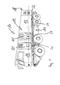
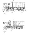
- each vehicle 10 comprises a chassis 11 and a semi-trailer 12 which is completely detachable from the chassis 11.
- the modular design of the vehicle 10 on the one hand and the detachable connection between the chassis 11 and the semi-trailer 12 on the other hand describes that the vehicles 10 are not only for assembly purposes, but in particular are also designed and set up to change the semi-trailer 12 depending on the application.
- the semi-trailers 12 include not only a functional unit 13, such as a container, but also a driver's cab 14.
- the driver's cab 14 may optionally also be connected to the functional unit 13 in such a way that access from the driver's cab 14 to the functional unit 13 and vice versa is possible.
- the driver's cab 14 and the functional unit 13 each have at least one door 15 or other suitable access options, such as e.g. a lock or the like, on.
- the driver's cab 14 preferably has a door 15 on both sides.
- the functional unit 13 preferably also has at least one door 15 on both sides and additionally a door 15 at the rear 16.
- the vehicles 10 are in particular designed and arranged such that they can be coupled to one another such that two doors 15 of mutually adjacent vehicles 10 are in overlap, so that a transition from vehicle 10 to vehicle 10 is ensured.
- the coupling of such vehicles 10 is basically known, so that a detailed description of the coupling mechanisms is dispensed with.
- Each vehicle 10 is associated with a device 17 according to the invention, which is designed and arranged to change the position of the trailer 12 to the chassis 11.
- the device 17 comprises a separate lifting unit 18 which is associated with the chassis 11.
- the lifting unit 18 may alternatively be associated with the semi-trailer 12.
- the advantage of a separate, so of the chassis type independent lifting unit 18 is in particular that this is also retrofitted.
- a design of the lifting unit 18 as a hydraulic unit 19, which is designed and set up exclusively for vertical alignment of the trailer 12 relative to the chassis 11.
- a pneumatic unit can also be used.
- the lifting unit 18 is adjustable by motor.
- the hydraulic unit 19 has three hydraulic cylinders 20, 21, 22 for forming a 3-point bearing.
- more hydraulic cylinders 20 to 22, namely in particular four hydraulic cylinders can be used.
- the position of the hydraulic cylinders 20 to 22 is variable.
- two hydraulic cylinders 20, 21 below the driver's cab 14 are arranged symmetrically to the central axis of the vehicle 10, while below the functional unit 13, a hydraulic cylinder 22 centrally is arranged on the central axis.
- the hydraulic cylinders 20 to 22 are fixed on the one hand to the chassis 11 and on the other hand to the trailer 12.
- the attachment itself can be fixed and in particular rigid, for compensation purposes but also at least partially articulated, be formed.
- the arrangement / placement of the hydraulic cylinders 20 to 22 and their attachment to the chassis 11 and semi-trailer 12 may of course also vary.
- the device 17, so in particular also the hydraulic unit 19, is connected to a (not shown) control.
- the distance between the chassis 11 and the semi-trailer 12 is individually controllable and / or controllable.
- the hydraulic cylinders 20 to 22 are individually controlled.
- the necessary information eg distance to the other vehicle, angular offset, height difference, etc.
- the chassis 11 and / or the semi-trailer 12 may also be assigned a camera or the like in the region of the stern 16. Special preference is the control by means of a remote control unit remotely controllable.
- the device 17 optionally also includes an adjusting unit (not shown) for horizontally adjusting the position / position of the trailer 12 relative to the chassis 11.
- the adjusting unit eg corresponding guides and drive means.
- the adjustment unit for the horizontal adjustment can be designed and set up for linear and / or rotary adjustment as a pneumatic, hydraulic or motor unit. Other conventional adjustment mechanisms are also used.
- the load of the semi-trailer 12 can be done in addition to the hydraulic cylinders 20 to 22 by additional means.
- two support and / or guide elements 23, 24 are provided which relieve the hydraulic cylinders 20 to 22.
- the two support and / or guide elements 23, 24 lie on the central axis of the vehicle 10.
- the number and / or position of the support and / or guide elements 23, 24 may vary.
- the support and / or guide elements 23, 24 may be telescopically supported, for example, also hydraulically, pneumatically or by motor.
- the support and / or guide elements 23, 24 can also be dispensed with (see, for example, FIG. 2 ).
- FIG. 4 an arbitrary functional arrangement 25 of several vehicles 10 is shown.
- four vehicles 10b are coupled to a central vehicle 10a on the rear side.
- the functional assembly 25 may be, for example, a collapsible hospital.
- This arrangement 25 represents a protected and mobile device made up of several of the above-described (large-capacity) vehicles 10.
- the protection classes of the vehicles 10 or of the devices 25 formed therefrom, for example the ABC protection or the like, can vary depending on the application.
- each vehicle 10 includes a chassis 11 and a semi-trailer 12.
- the semi-trailer 12 include not only a functional unit 13, such as a container, but also a driver's cab 14.
- the functional assembly 13 may be completely detachable from the chassis 11. But also the semi-trailer 12 can be completely detached from the chassis 11.
- the modular design of the vehicle 10 on the one hand and the detachable connection between the chassis 11 and the functional structure 13 or the semi-trailer 12 on the other hand describes that the vehicles 10 not only for assembly purposes, but in particular for changing the functional structure or the trailer 12 depending on Application can be designed and set up.
- driver's cab 14 may optionally also be connected to the functional unit 13 such that from the driver's cab 14 to the functional unit 13 and vice versa access is possible.
- the driver's cab 14 and the functional unit 13 can each have at least one door 15 or others outwards suitable access options, such as a lock or the like, have.
- the driver's cab 14 preferably has a door 15 on both sides.
- the functional unit 13 preferably also has at least one door 15 on both sides and additionally a door 15 at the rear 16.
- the vehicles 10 are designed and arranged such that they can be coupled to one another such that two doors 15 of mutually adjacent vehicles 10 are in overlap, so that a transition from one vehicle 10 to another vehicle 10 is ensured.
- the coupling of such vehicles 10 is basically known, so that a detailed description of the coupling mechanisms is dispensed with.
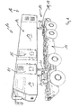
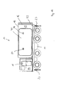
- the chassis 11 has a chassis lifting device 27 which is designed and arranged for vertical alignment of the chassis 11 relative to a ground.
- the chassis lifting device 27 has a lifting means 28 which can be pivoted downwards and locked.
- this lifting means 28 is a hydraulic cylinder.
- the vehicle 10 between the chassis 11 and the semi-trailer 12 has a linear guide device 29 as a load-bearing connection between the semi-trailer 12 and the chassis 11, which is designed and arranged for horizontal alignment of the semi-trailer 12 relative to the chassis 11.
- the linear guide device 29 By means of the linear guide device 29, the semi-trailer 12 can be moved horizontally relative to the chassis 11.
- Fig. 3 is shown by an offset 30 relative to the chassis 11 horizontally offset semi-trailer 12.
- the semi-trailer 12 is oriented horizontally relative to the chassis 11. The alignment has led to the offset 30.
- the pivotable lifting means 28 of the chassis lifting device 27 can be pivoted into the underbody 31 of the chassis 11 for the driving operation of the vehicle 10. In stationary mode or for coupling the vehicle to another vehicle, the lifting means 28 of the chassis lifting device 27 can be pivoted out of the underbody 31 of the chassis 11. Once the lifting means 28 are arranged at least substantially perpendicular to the chassis 11, they can be locked. In other words, the lifting means 27 can be pivoted out of the underbody 31 of the chassis 11 and / or pivoted into the underbody.
- the chassis lift device 27 may include a hydraulic unit having four hydraulic cylinders 32 for forming a four-point bearing. Of course, three hydraulic cylinders 32 or more than four hydraulic cylinders 32, namely in particular five, six, seven or eight hydraulic cylinders 32 can be used. The position and position of the hydraulic cylinders 32 is variable. In the embodiment shown, four hydraulic cylinders 32 are arranged below the chassis 11 symmetrically to the longitudinal and transverse axis of the vehicle 10. The hydraulic cylinders 32 are rotatably mounted at least at one end to the chassis 11 and have on the opposite end of a pedestal 33. Both the arrangement / placement of the hydraulic cylinder 32 and its attachment to the chassis 11 may vary.
- the linear guide means 29 may be integrated into the chassis 11 and / or the semi-trailer 12 and / or designed flat, that the chassis 11 and the trailer 12 are connected at least substantially without spacing. These embodiments are visible in particular in the area of the driver's cab 14.
- the cab 14 is arranged so close to the chassis that it rests almost on this. Thus, it is hardly possible that foreign bodies between the trailer and the chassis penetrate.
- the chassis lift device 27 and the linear guide device 29 may each be connected to a controller. With the control of the distance and / or the inclination angle between the chassis 11 and a substrate can be controlled and / or regulated. Further, by means of the controller, the horizontal offset 30 between the semi-trailer 12 and the chassis 11 can be controlled and / or regulated. The distance, the angle of inclination and / or the horizontal offset can also be controlled and / or regulated individually and / or independently of each other. For this purpose, the chassis lifting device 27 and / or the linear guide device 29 can also be remotely controllable. The lifting means 28 and / or the drive means of the linear guide device 29 may be controllable by means of control.
- the chassis are aligned vertically relative to the ground or the semi-trailer are aligned horizontally relative to the chassis.
- the controller can be connected to geometry sensors. These sensors may be mounted on the vehicle to measure, for example, the distance to another vehicle, the angular offset between the chassis and the ground, or an angular offset between the vehicle and another vehicle, the height difference between two vehicles, or other geometric data. These measured data can be transmitted to the controller by means of appropriate line and / or radio links.
- the controller may receive, evaluate and output such data to align the location and / or position of the trailer relative to the chassis, or the location of the chassis relative to the ground, to couple the vehicle to another vehicle.
- input means may be provided for manually controlling the chassis lifting device 27 and / or the linear guiding device 29.
- the chassis 11 and / or the semi-trailer 12 may be arranged preferably in the region of the stern 16, a camera and / or a pressure sensor. These can also be connected to the controller.
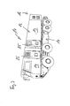
- the linear guide device may also have quick connection means 36 to connect containers, preferably commercial industrial containers, with the linear guide device.
- containers may also have container stilts 37.
- the vehicle 10 In order to firmly connect these container stilts 37 to the container 13, the vehicle 10 must be raised sharply by means of the chassis lifting device 27. Once the container stilts 37 are mounted under or on the container, the chassis 11 can be lowered with the chassis lift device 27 so far that the container stilts 37 touch the ground. Then the quick connection means 36 of the linear guide device can be released from the container 13.
- the chassis 11 can be completely lowered by means of the chassis lifting device 27.
- the lifting means 28 of the chassis lifting device 27 be designed telescopically.
- the lifting means 28 can be retracted so far that the tires 34 of the chassis 11 touch the ground and carry the chassis 11 as such. Due to the lowering of the chassis 11, this is as in Fig. 10 shown separated from the container 13 so that the vehicle 10 can drive out under the container 13.
- FIG. 11 an arbitrary functional arrangement 25 of several vehicles 10 is shown.
- four vehicles 10b are coupled to a central vehicle 10a on the rear side.
- the functional assembly 25 may be, for example, a collapsible hospital.
- This arrangement 25 represents a protected and mobile device made up of several of the vehicles 10 described above.
- the protection classes of the vehicles 10 or of the devices 25 formed therefrom, for example the ABC protection or the like, can vary depending on the application.
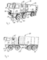
- FIGS. 12 to 15 illustrated vehicles according to a third embodiment of the invention are also assembled in a modular design.
- Each vehicle 10 comprises the chassis 11 and the semi-trailer 12 which is completely detachable from the chassis 11.
- the modular design of the vehicle 10 on the one hand and the detachable connection between the chassis 11 and the semi-trailer 12 on the other hand describes that the vehicles 10 not only for assembly purposes, but in particular are also designed and set up to change the semi-trailer 12 depending on the application.
- the semi-trailers 12 may include either the functional unit 13, for example, a container, or in addition also the driver's cab 14.
- the driver's cab 14 may optionally also be connected to the functional unit 13 in such a way that access from the driver's cab 14 to the functional unit 13 and vice versa is possible.
- the driver's cab 14 and the functional unit 13 each have at least one door 15 or other suitable access options, such as a lock or the like, on the outside.
- the driver's cab 14 preferably has a door on both sides.
- the functional unit 13 preferably also has at least one door 15 on both sides, and in addition at the rear 16 another door 15.
- the vehicles 10 are in particular designed and arranged such that they can be coupled to one another such that two doors 15 of adjacent vehicles 10 are in registration so that a transition from vehicle 10 to vehicle 10 is ensured is.
- the vehicle 10 additionally has one or two removable side walls 40.
- the vehicles 10 are coupled together on their longitudinal side to the function assembly 25, wherein first the removable side walls 40 are to be removed.
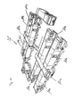
- Each vehicle 10 is associated with a device 17 according to the invention, which is designed and arranged to change the position of the trailer 12 relative to the chassis 11.
- the device 17 preferably comprises an adjusting unit 41 for the horizontal adjustment of the position of the trailer 12 relative to the chassis 11.
- the adjusting unit 41 has corresponding guides and drive means 42 for this purpose.
- the semi-trailer 12 is movably mounted on the chassis 11 and can be moved or displaced in a horizontal plane relative to the chassis 11. It is thus possible to move the semitrailers 12 of two vehicles 10 next to one another as close as possible to each other and to couple them to the functional arrangement 25 with one another.
- the adjustment unit 41 preferably includes a between the chassis 11 and the semi-trailer 12 horizontally movable intermediate plate 43.
- the semi-trailer 12 rests on the intermediate plate 43.
- the intermediate plate 43 is slidably mounted.
- the adjusting unit 41 comprises a frame 49 which is fixedly arranged on the chassis 11 and has at least one sliding region 44.
- the sliding region 44 forms a support with the underside 45 of the intermediate plate 43.
- the support is designed as a plain bearing.
- the support can also be set up as a ball or roller bearing.
- the adjustment unit 41 has at least two of the guides and two of the drive means 42.
- the adjusting unit 41 has two guides which are arranged at least substantially in the direction of the transverse axis of the vehicle 10.
- the intermediate plate 43 by means of the two queraxial arranged guides or drive means 42 are rotated relative to the vehicle longitudinal axis, that are rotationally moved. At least one of the guides or another of the drive means 42 is arranged orthogonal to the first-mentioned guides or drive means 42, so that the intermediate plate 43 is additionally movable in the direction of the longitudinal axis of the vehicle 10. In other words, the intermediate plate 43 is arbitrarily horizontally movable relative to the chassis 11, so both translationally in the direction of the longitudinal and transverse axis of the vehicle 10 and to a certain extent rotationally movable.
- Each of the guides comprises a guide element 46 arranged on the underside 45 of the intermediate plate 43 and a receiving element 47 arranged on the drive means 42.
- the guide is formed by a guide element 46 and a corresponding receiving element 47.
- the receiving element 47 is designed and configured in a manner corresponding to the guide element 46 such that the guide element 46 engages in the receiving element 47 in a positive and / or non-positive manner.
- the receiving element 47 is formed corresponding to the guide element 46 in such a way that it transmits a force in one direction from the drive means 42 to the guide element 46 and thus to the intermediate plate 43.
- the guide element 46 is formed for example as a metal plate which is fixedly arranged on the underside 45 of the intermediate plate 43.
- the receiving element 47 is correspondingly U-shaped, so that it forms a receiving space for the guide element 46. If the receiving element 47 is moved in one direction by means of the drive means 42, the intermediate plate 43 is simultaneously moved in this direction by the engagement of the guide element 46 in the receiving element 47. In order to allow movement of the intermediate plate 43 in a different direction, for example, out of the drawing plane or into it, the connection between the receiving element 47 and the guide element 46 is formed with play.
- the intermediate plate 43 is freely movable in the other direction and at the same time at least a partial rotation of the intermediate plate 43 is executable.
- the two free legs of the receiving element 47 are formed as rollers.
- the drive means 42 is a hydraulic unit.
- any other conventional drive may alternatively be used, for example an electromotive drive unit or the like.
- the frame 49, the intermediate plate 43 and the semi-trailer 12 have corresponding recesses 50 for receiving securing means.
- securing means serve for example provided with a split pin or bolts with a locking nut. In the state of the vehicle 10, the securing means are removed before moving the intermediate plate 43 or the semi-trailer 12.
- each of the vehicles 10 comprises the chassis lifting device 27, which has already been described in detail previously according to the second embodiment of the invention.
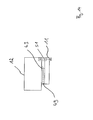
- the semitrailer 12 is further associated with at least one removably arranged lifting device 51.
- the lifting device 51 is designed to be pluggable, for example, such that the lifting device 51 can be attached laterally to the semi-trailer 12 or the functional unit 13. After two or more of the vehicles 10 have been vertically aligned by means of the chassis lifting device 27, the lifting devices 51 are arranged on the semi-trailer 12 and the trailer 12 is supported against the ground.
- the lifting device 51 is preferably designed and set up exclusively for vertical lifting or lifting of the semi-trailer 12 from the intermediate plate 43.
- the lifting device 51 serves to release the semi-trailer 12 from the intermediate plate 43 by lifting, so that the intermediate plate 43 is completely released and the respective vehicle 10 can be moved out below the semi-trailer 12.
- the lifting device 51 comprises an at least substantially horizontally arranged hydraulic device.
- the hydraulic device is adjustable in its length, so that the hydraulic device can be adapted to the respective distance between the ground and the semi-trailer 12. In this way, to lift the semi-trailer 12 from the intermediate plate 43, the required working travel of the hydraulic device is reduced to a minimum.
- the hydraulic device is by means of at least in Essentially horizontally oriented support member formed laterally connectable to the semi-trailer 12.
- the hydraulic device is arranged at a distance from the semi-trailer 12 or the functional unit 13 by means of the support element.
- the hydraulic device and the support element thus form an angular support arrangement, so that the chassis 11 or the vehicle 10 can be maneuvered without contact underneath the semitrailer 12 lifted by means of the hydraulic device and lifted off the intermediate plate 43.
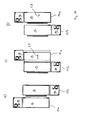
- FIG. 16 the coupling process of the vehicles 10 is shown by way of example with reference to two of the vehicles 10.
- Fig. 16a A second vehicle 10b is coupled to a first vehicle 10a, whose removable side wall 40 has already been removed on one side of the semi-trailer 12 or functional unit 13.
- the second vehicle 10b is moved as close as possible with its longitudinal side to the first vehicle 10a. Due to a minimum distance to be maintained between the vehicles 10a, 10b, a wedge-shaped gap remains between both vehicles 10a, 10b.
- the aforementioned adjusting unit 41 is, as in Fig.
- the semi-trailer 12 of the second vehicle 10b moves flush with the semi-trailer 12 of the first vehicle 10a, so that the semitrailers 12 of both vehicles 10a, 10b form the functional assembly 25 by placing the semi-trailer 12 over the side wall 40 removed Opening is connected by means of a sealing member 52 to the trailer 12 of the second vehicle 10 b.
- Fig. 17 shows by way of example a functional assembly 25 of several of the vehicles 10, which are coupled at different angles to each other. Some of the vehicles 10 are coupled to each other at an angle of 90 °, while other vehicles 10 are aligned parallel to one another, ie coupled at an angle of 180 °. Of course, any other coupling angle between 5 ° and 180 ° according to the present invention can be realized.
- This makes it possible to design the structure of the functional arrangement 25 as desired.
- at least one releasable sealing frame 53 is arranged on the functional unit 13 and is designed and set up as a sealing element for connecting two functional units 13.
- the sealing frame 53 substantially corresponds to the sealing element 52, However, it is removable.
- the removable sealing frame 53 is arranged at the rear 16.
- the semitrailer 12 or the functional units 13 of all embodiments of the invention have coupling means for connecting the semi-trailers 12 or the functional units 13 to the functional assembly 25.
- the coupling means each comprise receptacles for holding means, with which the semitrailer 12 are connectable to each other.
- the removable side wall 40 has at least two receptacles 54 for receiving at least two suspension elements 55.
- the receptacles 54 are formed corresponding to the suspension elements 55.
- the suspension elements 55 are formed, for example, as a bolt.
- the suspension elements 55 are arranged on the outside of a side wall 56 opposite the removable side wall 40.
- the suspension elements 55 and the receptacles 54 are arranged inclined upward.
- Fig. 19a shows the vehicles to be connected 10a, 10b in parallel alignment.
- the vehicle 10b is first turned 180 ° and brought close to the vehicle 10a.
- the semi-trailer 12 of the vehicle 10b is moved in the direction 57 of the semi-trailer 12 of the vehicle 10a.
- the removable side wall 40 is lifted out of its seat by means of the suspension elements 55 sliding in the receptacles 54 and is suspended via the suspension elements 55 or the receptacles 54 on the opposite side wall 56 of the vehicle 10b.
- FIG. 20d shows the vehicles 10a, 10b after removing the side wall 40 of the vehicle 10a.
- the vehicle 10b may be aligned in parallel with the vehicle 10a or any other vehicle 10 with the side wall 40 now hooked to the opposite side wall 56.
- the corresponding side wall 40 is lifted from its seat by moving the intermediate plate 43 in the direction of the arrow 57 analogous to the previously described process by means of the receptacles 54 and the suspension elements 55.
- the intermediate plate 43 or the semi-trailer 12 of the vehicle 10a is moved back into the starting position by moving in the direction of the arrow 58.
- a fourth embodiment of the invention which represents an advantageous development of the second embodiment, is characterized by the vehicle 10 in a modular design, namely with the chassis 11 and the semi-trailer 12, the semi-trailer 12 as a unit comprising the driver's cab 14 and the functional unit 13 in that the chassis 11 has the chassis lifting device 27, which is designed and arranged for vertical alignment of the chassis 11 relative to the ground, and wherein the vehicle 10 between the chassis 11 and the semi-trailer 12 has a linear guide device 29 as a load-bearing connection between the semi-trailer 12 and the chassis 11, which is designed and arranged for the horizontal alignment of the semi-trailer 12 relative to the chassis 11.
- the chassis lift device 27 and the linear guide device 29 can be collectively assigned as a device to the vehicle.
- the linear guide device 29 allows a horizontal orientation of the trailer 12 relative to the chassis 11. Since the linear guide device 29 is disposed between the chassis 11 and the semi-trailer 12, the semi-trailer 12 can be moved horizontally on the chassis 11.
- a linear guide of the linear guide device 29 may be, for example, a linear sliding guide, a linear roller guide or a roller guide. It may also be a single-axis or multi-axis linear guide. Since the linear guide device 29 is formed as a load-receiving connection between the semi-trailer 12 and the chassis 11 and is set up, for example, support loads and / or shear forces can be transmitted.
- a linear guide is characterized in this context as being particularly advantageous because a linear guide can be made very rigid, so that high forces and / or torques are transferable, without causing excessive strains, bends or torsions.
- a linear guide can be made very rigid, so that high forces and / or torques are transferable, without causing excessive strains, bends or torsions.
- it is possible even with dynamic loads by the trailer 12 and / or by the functional structure to allow a coupling of two vehicles 10, and to keep a caused by the changing load offset 30 between two coupled vehicles as low as possible.
- a rigid connection between the semi-trailer 12 and the chassis 11 is possible by means of the linear guide device 29, which also improves the rigidity of the vehicle.
- the linear guide device 29 for horizontal alignment of the trailer 12 relative to the chassis 11 comprises a linear guide device 29 with at least one corresponding degree of freedom and a suitably designed drive means.
- the degree of freedom of the linear guide may, for example, be parallel to a horizontal longitudinal axis of the chassis 11 and / or parallel to a horizontal transverse axis of the chassis 11.
- the aforementioned drive means may be designed and arranged accordingly.
- two vehicles 10 can be coupled together as precisely as possible.
- the chassis lifting device 27 and the linear guiding device 29 are separate and / or mutually independent devices.
- the chassis lifting device 27 and the linear guiding device 29 may be separated from one another, for example mechanically, hydraulically, pneumatically and / or electrically, and / or be independent of one another.
- the chassis lifting device 27 is arranged on the underbody of the chassis 11.
- the Linear guide device 29, however, is disposed between the chassis 11 and the semi-trailer 12.
- the chassis lifting device 27 to be hydraulically driven, whereas the linear guiding device 29 is driven, for example, electrically or pneumatically.
- a further advantageous development of the fourth embodiment is characterized in that the drive means of the linear guide device 29 is designed and set up at least substantially exclusively for load absorption along the at least one degree of freedom of the linear guide. Since the linear guide transmits no forces along the at least one degree of freedom, these can be transmitted by the drive means of the linear guide device 29 between the semi-trailer 12 and the chassis 11.
- the drive means of the linear guide device 29 can thus take on two tasks, namely the drive as such for horizontal alignment of the trailer 12 relative to the chassis 11 and the load-receiving connection along the at least one degree of freedom of the linear guide.
- a particularly advantageous variant of the drive means is configured in such a way that it exclusively transmits forces along the at least one degree of freedom of the linear guide.
- Such a drive means may be for example a hydraulic cylinder.
- the drive means of the linear guide device 29 is designed and set up as another conventional pneumatic, hydraulic or motor unit.
- An expedient development of the fourth embodiment is characterized in that the drive means of the linear guide device 29 is a further hydraulic device, and formed and set up in operative connection or in operative connection with the linear guide exclusively for horizontal alignment of the trailer relative to the chassis.
- the linear guide device 29 is integrated into the chassis 11 and / or in the semi-trailer 12 and / or configured flat, that the chassis 11 and the trailer 12 are connected at least substantially without spacing , The closer the semi-trailer 12 is connected to the chassis 11, the lower are the torques acting on the connection between the chassis and the semi-trailer 12.
- the linear guide of the linear guide device 29 all types of torque of the connection between the chassis 11 and semi-trailer 12th transferable.
- the linear guide device 29 may be configured such that one degree of freedom of the linear guide is exclusively formed and arranged along a power transmission direction of the connection between the chassis 11 and the semi-trailer 12.
- the linear guide of the linear guide device 29 preferably all torques are transmitted through the linear guide of the linear guide device 29. Due to the advantageous integration or flat design of the linear guide the forces acting on the linear guide forces can be kept relatively low, because the distance between the chassis 11 and the trailer 12 by the linear guide is not or only very slightly increased.
- the integration of the linear guide or its flat configuration has the advantage that a space between the chassis and semi-trailer is kept as small as possible, so that the vehicle provides protection at least in this area against the penetration of large foreign bodies, for example. At least substantially without spacing means in this context that the linear guide device 29 does not increase the distance between the chassis 11 and the semi-trailer 12 or only slightly in the vertical direction.
- a linear guide device 29 is designed, for example, flat when the distance between the trailer 12 and the chassis 11 is only a few centimeters, for example less than 15 cm, preferably less than 10 cm, more preferably less than 5 cm.
- the linear guide may comprise a plurality of linear guide elements, wherein the chassis 11 and the semi-trailer 12 each have at least one guide element.
- the chassis 11 may have, as a guide element, an inwardly projecting dovetail groove into which an outwardly projecting dovetail-shaped guide element of the trailer 12 engages. Together, the dovetail groove and the dovetail-shaped guide element can form a linear sliding guide.
- linear guide device 29 is integrated in the chassis 11 and / or in the semi-trailer 12 can therefore also mean that only the chassis-side or semi-trailer-side guide elements of the linear guide device 29 are integrated in the chassis 11 or in the semi-trailer 12. From the preceding example it can be seen that the dovetail groove is integrated in the semi-trailer 12.
- a further advantageous development of the fourth embodiment is characterized in that the functional unit is completely detachably connected to the driver's cab 14, the linear guide device 29 and / or the chassis 11.
- the vehicle 10 is basically modular.
- the functional unit 13 may for example be part of a mobile hospital, a canteen, a warehouse, a conference room or a battle stand. In other words, the functional unit 13 is exchangeable.
- the functional unit 13 can be connected to the linear guide device 29 by quick-connection means 36.
- quick-connection means 36 For example, hinged or retractable levers as linear guide element of the semi-trailer 12 or the functional unit 13 engage in groove-shaped linear guide elements of the chassis 11 to form a linear guide between the chassis 11 and the trailer 12 and the functional unit 13.
- the functional unit 13 is connected to the linear guide device 29 by quick-connection means 36.
- the functional unit 13 can be hooked into a rail element of the linear guide.
- the driver's cab 14 and the functional unit 13 can also be connected to one another by quick-connection means 36.
- the driver's cab 14 and the functional unit 13 are connected to each other in such a way that they have a common interior, which is preferably designed separable by doors or similar means.
- the semi-trailer 12 can be aligned horizontally as a unit.
Landscapes
- Engineering & Computer Science (AREA)
- Health & Medical Sciences (AREA)
- Public Health (AREA)
- Transportation (AREA)
- Mechanical Engineering (AREA)
- Vehicle Cleaning, Maintenance, Repair, Refitting, And Outriggers (AREA)
- Body Structure For Vehicles (AREA)
Priority Applications (1)
| Application Number | Priority Date | Filing Date | Title |
|---|---|---|---|
| PL11703654T PL2593333T3 (pl) | 2010-07-13 | 2011-02-04 | Pojazd o konstrukcji modułowej |
Applications Claiming Priority (3)
| Application Number | Priority Date | Filing Date | Title |
|---|---|---|---|
| DE102010027420A DE102010027420B4 (de) | 2010-07-13 | 2010-07-13 | Fahrzeug in modularer Bauweise, nämlich mit einem Chassis und einem Auflieger, mit einer Verstelleinrichtung für den Auflieger |
| DE202010016249U DE202010016249U1 (de) | 2010-07-13 | 2010-12-07 | Fahrzeug in modularer Bauweise, nämlich mit einem Chassis und einem Auflieger, mit einer Verstelleinrichtung für den Auflieger |
| PCT/EP2011/051674 WO2012007184A1 (de) | 2010-07-13 | 2011-02-04 | Fahrzeug in modularer bauweise |
Publications (2)
| Publication Number | Publication Date |
|---|---|
| EP2593333A1 EP2593333A1 (de) | 2013-05-22 |
| EP2593333B1 true EP2593333B1 (de) | 2014-10-01 |
Family
ID=43829211
Family Applications (1)
| Application Number | Title | Priority Date | Filing Date |
|---|---|---|---|
| EP11703654.1A Active EP2593333B1 (de) | 2010-07-13 | 2011-02-04 | Fahrzeug in modularer bauweise |
Country Status (4)
| Country | Link |
|---|---|
| EP (1) | EP2593333B1 (pl) |
| DE (2) | DE102010027420B4 (pl) |
| PL (1) | PL2593333T3 (pl) |
| WO (1) | WO2012007184A1 (pl) |
Cited By (1)
| Publication number | Priority date | Publication date | Assignee | Title |
|---|---|---|---|---|
| EP3303090B1 (de) | 2015-05-25 | 2020-01-08 | Rapid Housing Systems GmbH | Bausatz für ein modulares gebäude mit einem unterfahrjustierer |
Families Citing this family (7)
| Publication number | Priority date | Publication date | Assignee | Title |
|---|---|---|---|---|
| DE102011053306A1 (de) | 2011-09-06 | 2013-03-07 | Drehtainer Gmbh Spezial Container- Und Fahrzeugbau | Fahrzeug mit Auflieger in modularer Bauweise |
| DE202011051213U1 (de) | 2011-09-06 | 2011-12-01 | Drehtainer Gmbh Spezial Container- Und Fahrzeugbau | Fahrzeug mit Auflieger in modularer Bauweise |
| CN103300986A (zh) * | 2013-05-14 | 2013-09-18 | 郑静晨 | 一种智能拓展车载方舱医院 |
| DE202016100825U1 (de) * | 2016-02-17 | 2017-05-19 | Alois Kober Gmbh | Fahrgestell |
| DE102018220377B4 (de) | 2018-11-27 | 2021-04-22 | Deutsches Zentrum für Luft- und Raumfahrt e.V. | Fahrzeug, Fahrzeugsystem und Verfahren zum Betreiben eines Fahrzeugsystems |
| CN110154999A (zh) * | 2019-05-30 | 2019-08-23 | 姚先同 | 一种可伸缩汽车底盘及使用该底盘的汽车 |
| CN115930029B (zh) * | 2022-11-11 | 2025-03-14 | 安徽阿莫斯流体技术有限公司 | 一种子母式清淤车结构 |
Family Cites Families (10)
| Publication number | Priority date | Publication date | Assignee | Title |
|---|---|---|---|---|
| FR2170843A1 (en) * | 1972-02-03 | 1973-09-21 | Bauduret Jacques | Mobile rooms - having two synthetic insulated shells |
| US3909057A (en) * | 1973-10-29 | 1975-09-30 | Joe M Guthry | Combination camper and boat trailer mechanism |
| SE403092B (sv) * | 1976-12-13 | 1978-07-31 | Lovgren Sten | Anordning vid anleggningar for overforing av lastenheter till och fran en forsta berare, innefattande en overforingsapparat anordnad pa en andra berare |
| FR2670233B1 (fr) * | 1990-12-06 | 1995-01-06 | Lohr Ind | Abri-conteneur habitable a volume interieur extensible. |
| DE19927917A1 (de) * | 1999-06-18 | 2000-12-21 | Seefluth Christian U | Mobile Wohn-/ Büroanlage |
| DE20016874U1 (de) * | 2000-09-29 | 2001-02-01 | Kögel Fahrzeugwerke AG, 89079 Ulm | Versorgungsfahrzeug mit austauschbarem Aufbau und separater Bedienstation |
| DE102005000944A1 (de) * | 2005-01-07 | 2006-07-27 | Helmut Backes | Lastkraftwagen |
| DE202007006320U1 (de) * | 2007-05-03 | 2007-10-04 | Rohde, Matthias | Mobiler Medienraum |
| DE102007030107B4 (de) * | 2007-06-28 | 2013-03-21 | Ewo Fluid Power Gmbh | Verfahren und System zum elektrohydraulischen Ausrichten von Tragkörpern |
| US7845447B2 (en) * | 2007-10-09 | 2010-12-07 | Victor Samaniego | System and methods for adjustment of vehicle bodies |
-
2010
- 2010-07-13 DE DE102010027420A patent/DE102010027420B4/de active Active
- 2010-12-07 DE DE202010016249U patent/DE202010016249U1/de not_active Expired - Lifetime
-
2011
- 2011-02-04 PL PL11703654T patent/PL2593333T3/pl unknown
- 2011-02-04 WO PCT/EP2011/051674 patent/WO2012007184A1/de not_active Ceased
- 2011-02-04 EP EP11703654.1A patent/EP2593333B1/de active Active
Cited By (1)
| Publication number | Priority date | Publication date | Assignee | Title |
|---|---|---|---|---|
| EP3303090B1 (de) | 2015-05-25 | 2020-01-08 | Rapid Housing Systems GmbH | Bausatz für ein modulares gebäude mit einem unterfahrjustierer |
Also Published As
| Publication number | Publication date |
|---|---|
| DE202010016249U1 (de) | 2011-03-31 |
| DE102010027420A1 (de) | 2012-01-19 |
| WO2012007184A1 (de) | 2012-01-19 |
| DE102010027420B4 (de) | 2012-05-16 |
| PL2593333T3 (pl) | 2015-03-31 |
| DE102010027420A8 (de) | 2012-03-22 |
| EP2593333A1 (de) | 2013-05-22 |
Similar Documents
| Publication | Publication Date | Title |
|---|---|---|
| EP2593333B1 (de) | Fahrzeug in modularer bauweise | |
| DE69004018T2 (de) | Ausziehbare, starre struktur. | |
| EP2260818B1 (de) | Ladelift | |
| DE102020135143B4 (de) | Hebevorrichtung sowie Hebebühne zum Heben und Senken von Fahrzeugen oder Lasten | |
| EP2601349B1 (de) | Schienensystem mit stützbeschlag zum höhenverstellbaren abstützen einer trag- und führungsschiene | |
| DE102017220580A1 (de) | Transportsystem zum automatisierten Transportieren eines Fahrzeugs mit mindestens einem Transportroboter | |
| EP3933109A1 (de) | Bodenbearbeitungsmaschine mit längenveränderlicher steigeinrichtung mit mehreren unterschiedlichen steigbereiten betriebsstellungen | |
| DE102014002480B4 (de) | Verfahren und Einrichtung zum Nivellieren und Verbinden von mindestens zwei in einer Reihe auf einem Untergrund abgestellten begehbaren Container-Modulen zu einem modularen Gebäude | |
| EP3838635A1 (de) | Nivelliereinrichtung | |
| EP3409554A1 (de) | Schienenfahrzeug mit allradantrieb | |
| DE2203082C3 (de) | Fahrzeug, insbesondere Lastkraftwagen, für den Transport von vorgefertigten Fertiggaragen | |
| DE102014008720B4 (de) | Schwerlastfahrzeug mit Staplerfunktion | |
| EP3303090A1 (de) | Leichtes modulares gebäude | |
| CH695454A5 (de) | Abstell- und Hebevorrichtung für Container. | |
| DE102021118688A1 (de) | Selbstfahrende bodenfräsmaschine, adapterset für eine bodenfräsmaschine sowie verfahren zum inkrementellen verschieben und/oder vergrössern des hubbereiches | |
| DE102014220132B4 (de) | Mobilkran und Verfahren zum Abstützen eines derartigen Mobilkrans | |
| DE102017110215A1 (de) | Stempelbühne für Fahrzeuge sowie Hubeinrichtung für Stempelbühne | |
| DE29922410U1 (de) | Vorrichtung zum Richten von Karosserien von Fahrzeugen | |
| EP2957537B1 (de) | Schwerlastfahrzeug mit staplerfunktion | |
| EP2753500B1 (de) | Fahrzeug mit auflieger in modularer bauweise | |
| DE202017105233U1 (de) | In eine platzsparende Anordnung bringbarer Rotorantriebsstrang | |
| DE3244318A1 (de) | Hebeeinrichtung fuer ein kraftfahrzeug oder dergl. | |
| DE10024027B4 (de) | Wechselvorrichtung für ein Nutzfahrzeug | |
| DE9203607U1 (de) | Allseitig rangierbares, gleisloses Flurfördergerät mit teleskopierbarem Trägergestell | |
| DE19849444A1 (de) | Vorrichtung zum Abstellen von Kraftfahrzeugen |
Legal Events
| Date | Code | Title | Description |
|---|---|---|---|
| PUAI | Public reference made under article 153(3) epc to a published international application that has entered the european phase |
Free format text: ORIGINAL CODE: 0009012 |
|
| 17P | Request for examination filed |
Effective date: 20130212 |
|
| AK | Designated contracting states |
Kind code of ref document: A1 Designated state(s): AL AT BE BG CH CY CZ DE DK EE ES FI FR GB GR HR HU IE IS IT LI LT LU LV MC MK MT NL NO PL PT RO RS SE SI SK SM TR |
|
| DAX | Request for extension of the european patent (deleted) | ||
| GRAP | Despatch of communication of intention to grant a patent |
Free format text: ORIGINAL CODE: EPIDOSNIGR1 |
|
| INTG | Intention to grant announced |
Effective date: 20140414 |
|
| GRAS | Grant fee paid |
Free format text: ORIGINAL CODE: EPIDOSNIGR3 |
|
| GRAA | (expected) grant |
Free format text: ORIGINAL CODE: 0009210 |
|
| AK | Designated contracting states |
Kind code of ref document: B1 Designated state(s): AL AT BE BG CH CY CZ DE DK EE ES FI FR GB GR HR HU IE IS IT LI LT LU LV MC MK MT NL NO PL PT RO RS SE SI SK SM TR |
|
| REG | Reference to a national code |
Ref country code: GB Ref legal event code: FG4D Free format text: NOT ENGLISH |
|
| REG | Reference to a national code |
Ref country code: CH Ref legal event code: EP Ref country code: AT Ref legal event code: REF Ref document number: 689347 Country of ref document: AT Kind code of ref document: T Effective date: 20141015 |
|
| REG | Reference to a national code |
Ref country code: IE Ref legal event code: FG4D Free format text: LANGUAGE OF EP DOCUMENT: GERMAN |
|
| REG | Reference to a national code |
Ref country code: DE Ref legal event code: R096 Ref document number: 502011004515 Country of ref document: DE Effective date: 20141106 |
|
| REG | Reference to a national code |
Ref country code: CH Ref legal event code: NV Representative=s name: E. BLUM AND CO. AG PATENT- UND MARKENANWAELTE , CH |
|
| REG | Reference to a national code |
Ref country code: NL Ref legal event code: T3 |
|
| REG | Reference to a national code |
Ref country code: FR Ref legal event code: PLFP Year of fee payment: 5 |
|
| REG | Reference to a national code |
Ref country code: NO Ref legal event code: T2 Effective date: 20141001 |
|
| REG | Reference to a national code |
Ref country code: LT Ref legal event code: MG4D |
|
| REG | Reference to a national code |
Ref country code: PL Ref legal event code: T3 |
|
| PG25 | Lapsed in a contracting state [announced via postgrant information from national office to epo] |
Ref country code: LT Free format text: LAPSE BECAUSE OF FAILURE TO SUBMIT A TRANSLATION OF THE DESCRIPTION OR TO PAY THE FEE WITHIN THE PRESCRIBED TIME-LIMIT Effective date: 20141001 Ref country code: FI Free format text: LAPSE BECAUSE OF FAILURE TO SUBMIT A TRANSLATION OF THE DESCRIPTION OR TO PAY THE FEE WITHIN THE PRESCRIBED TIME-LIMIT Effective date: 20141001 Ref country code: ES Free format text: LAPSE BECAUSE OF FAILURE TO SUBMIT A TRANSLATION OF THE DESCRIPTION OR TO PAY THE FEE WITHIN THE PRESCRIBED TIME-LIMIT Effective date: 20141001 Ref country code: PT Free format text: LAPSE BECAUSE OF FAILURE TO SUBMIT A TRANSLATION OF THE DESCRIPTION OR TO PAY THE FEE WITHIN THE PRESCRIBED TIME-LIMIT Effective date: 20150202 Ref country code: CZ Free format text: LAPSE BECAUSE OF FAILURE TO SUBMIT A TRANSLATION OF THE DESCRIPTION OR TO PAY THE FEE WITHIN THE PRESCRIBED TIME-LIMIT Effective date: 20141001 Ref country code: IS Free format text: LAPSE BECAUSE OF FAILURE TO SUBMIT A TRANSLATION OF THE DESCRIPTION OR TO PAY THE FEE WITHIN THE PRESCRIBED TIME-LIMIT Effective date: 20150201 |
|
| PG25 | Lapsed in a contracting state [announced via postgrant information from national office to epo] |
Ref country code: LV Free format text: LAPSE BECAUSE OF FAILURE TO SUBMIT A TRANSLATION OF THE DESCRIPTION OR TO PAY THE FEE WITHIN THE PRESCRIBED TIME-LIMIT Effective date: 20141001 Ref country code: SE Free format text: LAPSE BECAUSE OF FAILURE TO SUBMIT A TRANSLATION OF THE DESCRIPTION OR TO PAY THE FEE WITHIN THE PRESCRIBED TIME-LIMIT Effective date: 20141001 Ref country code: HR Free format text: LAPSE BECAUSE OF FAILURE TO SUBMIT A TRANSLATION OF THE DESCRIPTION OR TO PAY THE FEE WITHIN THE PRESCRIBED TIME-LIMIT Effective date: 20141001 Ref country code: RS Free format text: LAPSE BECAUSE OF FAILURE TO SUBMIT A TRANSLATION OF THE DESCRIPTION OR TO PAY THE FEE WITHIN THE PRESCRIBED TIME-LIMIT Effective date: 20141001 Ref country code: CY Free format text: LAPSE BECAUSE OF FAILURE TO SUBMIT A TRANSLATION OF THE DESCRIPTION OR TO PAY THE FEE WITHIN THE PRESCRIBED TIME-LIMIT Effective date: 20141001 Ref country code: GR Free format text: LAPSE BECAUSE OF FAILURE TO SUBMIT A TRANSLATION OF THE DESCRIPTION OR TO PAY THE FEE WITHIN THE PRESCRIBED TIME-LIMIT Effective date: 20150102 |
|
| PG25 | Lapsed in a contracting state [announced via postgrant information from national office to epo] |
Ref country code: BE Free format text: LAPSE BECAUSE OF NON-PAYMENT OF DUE FEES Effective date: 20150228 |
|
| REG | Reference to a national code |
Ref country code: DE Ref legal event code: R097 Ref document number: 502011004515 Country of ref document: DE |
|
| PG25 | Lapsed in a contracting state [announced via postgrant information from national office to epo] |
Ref country code: RO Free format text: LAPSE BECAUSE OF FAILURE TO SUBMIT A TRANSLATION OF THE DESCRIPTION OR TO PAY THE FEE WITHIN THE PRESCRIBED TIME-LIMIT Effective date: 20141001 Ref country code: DK Free format text: LAPSE BECAUSE OF FAILURE TO SUBMIT A TRANSLATION OF THE DESCRIPTION OR TO PAY THE FEE WITHIN THE PRESCRIBED TIME-LIMIT Effective date: 20141001 Ref country code: EE Free format text: LAPSE BECAUSE OF FAILURE TO SUBMIT A TRANSLATION OF THE DESCRIPTION OR TO PAY THE FEE WITHIN THE PRESCRIBED TIME-LIMIT Effective date: 20141001 Ref country code: SK Free format text: LAPSE BECAUSE OF FAILURE TO SUBMIT A TRANSLATION OF THE DESCRIPTION OR TO PAY THE FEE WITHIN THE PRESCRIBED TIME-LIMIT Effective date: 20141001 |
|
| PLBE | No opposition filed within time limit |
Free format text: ORIGINAL CODE: 0009261 |
|
| STAA | Information on the status of an ep patent application or granted ep patent |
Free format text: STATUS: NO OPPOSITION FILED WITHIN TIME LIMIT |
|
| PG25 | Lapsed in a contracting state [announced via postgrant information from national office to epo] |
Ref country code: IT Free format text: LAPSE BECAUSE OF FAILURE TO SUBMIT A TRANSLATION OF THE DESCRIPTION OR TO PAY THE FEE WITHIN THE PRESCRIBED TIME-LIMIT Effective date: 20141001 |
|
| REG | Reference to a national code |
Ref country code: DE Ref legal event code: R119 Ref document number: 502011004515 Country of ref document: DE |
|
| 26N | No opposition filed |
Effective date: 20150702 |
|
| PG25 | Lapsed in a contracting state [announced via postgrant information from national office to epo] |
Ref country code: LU Free format text: LAPSE BECAUSE OF FAILURE TO SUBMIT A TRANSLATION OF THE DESCRIPTION OR TO PAY THE FEE WITHIN THE PRESCRIBED TIME-LIMIT Effective date: 20150204 |
|
| PG25 | Lapsed in a contracting state [announced via postgrant information from national office to epo] |
Ref country code: MC Free format text: LAPSE BECAUSE OF FAILURE TO SUBMIT A TRANSLATION OF THE DESCRIPTION OR TO PAY THE FEE WITHIN THE PRESCRIBED TIME-LIMIT Effective date: 20141001 |
|
| REG | Reference to a national code |
Ref country code: IE Ref legal event code: MM4A |
|
| PG25 | Lapsed in a contracting state [announced via postgrant information from national office to epo] |
Ref country code: IE Free format text: LAPSE BECAUSE OF NON-PAYMENT OF DUE FEES Effective date: 20150204 Ref country code: DE Free format text: LAPSE BECAUSE OF NON-PAYMENT OF DUE FEES Effective date: 20150901 |
|
| REG | Reference to a national code |
Ref country code: FR Ref legal event code: PLFP Year of fee payment: 6 |
|
| PG25 | Lapsed in a contracting state [announced via postgrant information from national office to epo] |
Ref country code: SI Free format text: LAPSE BECAUSE OF FAILURE TO SUBMIT A TRANSLATION OF THE DESCRIPTION OR TO PAY THE FEE WITHIN THE PRESCRIBED TIME-LIMIT Effective date: 20141001 |
|
| PG25 | Lapsed in a contracting state [announced via postgrant information from national office to epo] |
Ref country code: MT Free format text: LAPSE BECAUSE OF FAILURE TO SUBMIT A TRANSLATION OF THE DESCRIPTION OR TO PAY THE FEE WITHIN THE PRESCRIBED TIME-LIMIT Effective date: 20141001 |
|
| REG | Reference to a national code |
Ref country code: FR Ref legal event code: PLFP Year of fee payment: 7 |
|
| PG25 | Lapsed in a contracting state [announced via postgrant information from national office to epo] |
Ref country code: BG Free format text: LAPSE BECAUSE OF FAILURE TO SUBMIT A TRANSLATION OF THE DESCRIPTION OR TO PAY THE FEE WITHIN THE PRESCRIBED TIME-LIMIT Effective date: 20141001 Ref country code: SM Free format text: LAPSE BECAUSE OF FAILURE TO SUBMIT A TRANSLATION OF THE DESCRIPTION OR TO PAY THE FEE WITHIN THE PRESCRIBED TIME-LIMIT Effective date: 20141001 Ref country code: HU Free format text: LAPSE BECAUSE OF FAILURE TO SUBMIT A TRANSLATION OF THE DESCRIPTION OR TO PAY THE FEE WITHIN THE PRESCRIBED TIME-LIMIT; INVALID AB INITIO Effective date: 20110204 |
|
| PG25 | Lapsed in a contracting state [announced via postgrant information from national office to epo] |
Ref country code: TR Free format text: LAPSE BECAUSE OF FAILURE TO SUBMIT A TRANSLATION OF THE DESCRIPTION OR TO PAY THE FEE WITHIN THE PRESCRIBED TIME-LIMIT Effective date: 20141001 |
|
| REG | Reference to a national code |
Ref country code: FR Ref legal event code: PLFP Year of fee payment: 8 |
|
| PG25 | Lapsed in a contracting state [announced via postgrant information from national office to epo] |
Ref country code: MK Free format text: LAPSE BECAUSE OF FAILURE TO SUBMIT A TRANSLATION OF THE DESCRIPTION OR TO PAY THE FEE WITHIN THE PRESCRIBED TIME-LIMIT Effective date: 20141001 |
|
| PG25 | Lapsed in a contracting state [announced via postgrant information from national office to epo] |
Ref country code: AL Free format text: LAPSE BECAUSE OF FAILURE TO SUBMIT A TRANSLATION OF THE DESCRIPTION OR TO PAY THE FEE WITHIN THE PRESCRIBED TIME-LIMIT Effective date: 20141001 |
|
| P01 | Opt-out of the competence of the unified patent court (upc) registered |
Effective date: 20230508 |
|
| PGFP | Annual fee paid to national office [announced via postgrant information from national office to epo] |
Ref country code: NL Payment date: 20250220 Year of fee payment: 15 |
|
| PGFP | Annual fee paid to national office [announced via postgrant information from national office to epo] |
Ref country code: NO Payment date: 20250218 Year of fee payment: 15 |
|
| PGFP | Annual fee paid to national office [announced via postgrant information from national office to epo] |
Ref country code: AT Payment date: 20250217 Year of fee payment: 15 Ref country code: CH Payment date: 20250301 Year of fee payment: 15 |
|
| PGFP | Annual fee paid to national office [announced via postgrant information from national office to epo] |
Ref country code: FR Payment date: 20250219 Year of fee payment: 15 Ref country code: PL Payment date: 20250108 Year of fee payment: 15 |
|
| PGFP | Annual fee paid to national office [announced via postgrant information from national office to epo] |
Ref country code: GB Payment date: 20250108 Year of fee payment: 15 |