EP2590591B1 - Verfahren zur herstellung einer zahnmedizinischen bohrschablone - Google Patents
Verfahren zur herstellung einer zahnmedizinischen bohrschablone Download PDFInfo
- Publication number
- EP2590591B1 EP2590591B1 EP11741416.9A EP11741416A EP2590591B1 EP 2590591 B1 EP2590591 B1 EP 2590591B1 EP 11741416 A EP11741416 A EP 11741416A EP 2590591 B1 EP2590591 B1 EP 2590591B1
- Authority
- EP
- European Patent Office
- Prior art keywords
- blank
- drilling template
- guide bore
- drilling
- template
- Prior art date
- Legal status (The legal status is an assumption and is not a legal conclusion. Google has not performed a legal analysis and makes no representation as to the accuracy of the status listed.)
- Not-in-force
Links
Images

Classifications
-
- A—HUMAN NECESSITIES
- A61—MEDICAL OR VETERINARY SCIENCE; HYGIENE
- A61C—DENTISTRY; APPARATUS OR METHODS FOR ORAL OR DENTAL HYGIENE
- A61C1/00—Dental machines for boring or cutting ; General features of dental machines or apparatus, e.g. hand-piece design
- A61C1/08—Machine parts specially adapted for dentistry
- A61C1/082—Positioning or guiding, e.g. of drills
- A61C1/084—Positioning or guiding, e.g. of drills of implanting tools
-
- A—HUMAN NECESSITIES
- A61—MEDICAL OR VETERINARY SCIENCE; HYGIENE
- A61C—DENTISTRY; APPARATUS OR METHODS FOR ORAL OR DENTAL HYGIENE
- A61C13/00—Dental prostheses; Making same
-
- A—HUMAN NECESSITIES
- A61—MEDICAL OR VETERINARY SCIENCE; HYGIENE
- A61C—DENTISTRY; APPARATUS OR METHODS FOR ORAL OR DENTAL HYGIENE
- A61C13/00—Dental prostheses; Making same
- A61C13/0003—Making bridge-work, inlays, implants or the like
- A61C13/0004—Computer-assisted sizing or machining of dental prostheses
-
- A—HUMAN NECESSITIES
- A61—MEDICAL OR VETERINARY SCIENCE; HYGIENE
- A61C—DENTISTRY; APPARATUS OR METHODS FOR ORAL OR DENTAL HYGIENE
- A61C13/00—Dental prostheses; Making same
- A61C13/12—Tools for fastening artificial teeth; Holders, clamps, or stands for artificial teeth
-
- A—HUMAN NECESSITIES
- A61—MEDICAL OR VETERINARY SCIENCE; HYGIENE
- A61C—DENTISTRY; APPARATUS OR METHODS FOR ORAL OR DENTAL HYGIENE
- A61C3/00—Dental tools or instruments
- A61C3/02—Tooth drilling or cutting instruments; Instruments acting like a sandblast machine
-
- A—HUMAN NECESSITIES
- A61—MEDICAL OR VETERINARY SCIENCE; HYGIENE
- A61C—DENTISTRY; APPARATUS OR METHODS FOR ORAL OR DENTAL HYGIENE
- A61C8/00—Means to be fixed to the jaw-bone for consolidating natural teeth or for fixing dental prostheses thereon; Dental implants; Implanting tools
-
- G—PHYSICS
- G06—COMPUTING OR CALCULATING; COUNTING
- G06F—ELECTRIC DIGITAL DATA PROCESSING
- G06F30/00—Computer-aided design [CAD]
-
- A—HUMAN NECESSITIES
- A61—MEDICAL OR VETERINARY SCIENCE; HYGIENE
- A61C—DENTISTRY; APPARATUS OR METHODS FOR ORAL OR DENTAL HYGIENE
- A61C13/00—Dental prostheses; Making same
- A61C13/0003—Making bridge-work, inlays, implants or the like
- A61C13/0022—Blanks or green, unfinished dental restoration parts
Definitions
- the invention relates to a method for producing a dental surgical template having a guide bore and a bearing surface, wherein a 3D virtual drill template model of the surgical template with a virtual guide bore along a guide bore axis and with a virtual support surface is present.
- the manual "Production and Application of an Individual Drilling Template” by Straumann GmbH discloses a manufacturing method of a drilling template.
- a situation model is made of plaster.
- a plastic splint is deep-drawn onto the sensation model.
- a second gypsum model is produced, sawed at the planned implant position, that transmits measured bone profile and fixed an implant axis.
- a wax-up of the planned restoration is made on the original situation model.
- a duplicate of the wax-up model is produced and a plastic rail is deep-drawn on it.
- the new plastic splint is transferred to the situation model.
- a seventh step the determined implant position and implant axis are marked on the situation model and by means of a parallelometer with a pilot drill the bore performed.
- a titanium pin is inserted into the hole.
- a new plastic rail is deep-drawn over the titanium pin inserted in the model.
- the plastic rail is removed from the model and the titanium pin is replaced by a shorter titanium pin.
- the plastic splint is placed on the previously made model with the bone profile drawn in and the implant axis is checked. If necessary, the position and direction of the hole can still be corrected.
- a titanium pin with a gradation is inserted into the hole and any possible undercuts blocked with plaster, wax or plastic.
- a new plastic rail is deep-drawn via the titanium pin with gradation.
- an occlusal opening is cut or ground into the plastic splint and a drill sleeve with an edge is inserted into the plastic splint.
- the plastic splint is ground or cut in the area of the implantation site.
- a drill sleeve can be slipped over the titanium pin and the four of the rig can be fixed with plastic or gypsum.
- a plastic rail is deep-drawn over the drill sleeve and the drill hole ground free for receiving the pilot drill.
- DE 199 52 962 A1 discloses a method of constructing a dental implant drilling aid by first performing an X-ray of the jaw and then a three-dimensional optical measurement of the visible surface of the jaw and teeth. The measurement records from the radiograph and the three-dimensional optical Recording are correlated with each other. On the basis of existing information, such as the type and position of the implant relative to the adjacent teeth, a template is planned and generated, which rests on the adjacent teeth and thereby the exact hole of the implant guide hole is made possible. Based on the X-ray data, the implant can be determined and positioned in a known manner.
- an implant aid in the form of a drilling template can be ground by means of a CAD / CAM unit.
- a CAD / CAM machine is able to produce the drilling template with the negative of the occlusal surfaces and a guide run for the drill.
- a stop is transmitted, which determines the drilling depth.
- WO 99/32045 discloses a method of making a dental drilling aid for implants. First, a three-dimensional computer image is modeled using a jaw image with respect to an impression surface. Thereafter, the location and depth of the drilled holes are determined and a set of implant borehole coordinates are fed to a computerized manufacturing machine. Using a precision tool, a drill guide socket is prepared in the drill body for each of the previously fed well coordinate sets with a well position and well orientation determined from the jaw section.
- EP 2 072 018 discloses a method for making a dental surgical template from a blank, wherein there is a virtual 3D blank model of the blank with a virtual guide bore axis and with a virtual bearing surface.
- a disadvantage of these methods is that most CAD / CAM machines are limited in their degrees of freedom and, in particular, windings that are not skewed to one another are not feasible. Therefore, the production of surgical guides by means of a CAD / CAM machine only possible for limited indications.
- the production of the drilling template is done either individually in the laboratory or after previous CAD / CAM planning centrally, for example using a Hexapod whose construction allows movement of the object to be machined in all six degrees of freedom, and by means of a parallelometer for performing vertical holes , CT-DVT stencils, bite plates and jaw models made of gypsum are usually used for central production. These are mounted on the intricately designed Hexapod and adjusted with the aid of several measuring points. This process is very complicated and therefore error-prone.
- the object of this invention is therefore to provide a method which allows the production of any drilling template with skewed drilling axes using a conventional manufacturing machine with limited degrees of freedom.
- the subject invention is a method for making a dental surgical template from a blank having a guide bore and a bearing surface, wherein a 3D virtual template template of the surgical template is provided with a virtual guide bore along a guide bore axis and with a virtual bearing surface, wherein i. the virtual 3D drill template model is placed virtually within a blank 3D template of the blank to extract the template from the blank according to the shape and location of the 3D virtual template template within the 3D blank model, ii.
- a passage point of the guide bore axis is determined on an outer side of the 3D blank model and at the point of passage of the guide bore axis on the outside of the blank a mark is attached, wherein the mark at the point of passage of the guide bore axis in shape a recess is placed, iii. or wherein on an outside of the virtual 3D Bohrschablonenmodells a passage point of the guide bore axis is determined and during or after the working out of the drilling template from the blank at the point of passage on the outside of the drilling template a mark is attached, wherein the mark on the passage point of the guide bore axis is attached in the form of a depression.
- the dental surgical template to be produced may be any desired surgical template, such as a minimally invasive surgery surgical guide worn by the adjacent teeth, as well as a surgical template worn by the jawbone for so-called "open flap" surgery.
- the drilling template can be manufactured both for pilot bores and for inserting insertion sleeves.
- the guide bore is used to guide a drill to perform the planned implant bore for insertion of an implant as calculated in implant planning.
- the drill can be a so-called pilot drill.
- the guide bore may be configured such that a drill sleeve can be adjusted in the guide bore, with the inner surface of the drill sleeve serving to guide the drill.
- an X-ray of the jaw and a three-dimensional optical measurement of the visible surface of the jaw and teeth may be used to virtually fix the implant type and implant location relative to the jaw. In particular, the exact location, the relative angle to the jaw and the depth of the individual holes for inserting the implants planned.
- a virtual 3D drilling template model of the drilling template is then planned, which has virtual guide bores and a virtual bearing surface, wherein the bearing surface is preferably shaped as a negative counterpart to the surface of the adjacent teeth.
- the planned 3D surgical template model of the surgical template is the starting point of the present inventive method.
- the virtual 3D drill template model is placed virtually within the blank 3D model of a blank. This can be done using a computer with a monitor and a mouse, where the user can use virtual tools to rotate and move the 3D template model within the 3D blank model.
- the position data can be stored.
- a blank made of ceramic or plastic can be used, which is large enough in size to work out the drilling template.
- the blank may be any geometric basic shape in its dimensions, wherein it does not include patient-related elements, such as an impression of the patient's teeth.
- the bucket is worked by means of a manufacturing device, which may be a conventional CAD / CAM device with limited degrees of freedom.
- a manufacturing device which may be a conventional CAD / CAM device with limited degrees of freedom.
- virtually one or more points of passage of the guide bore axis by means of a computer determined on the outside of the 3D blank model or on the outside of the 3D virtual drill template model. This can be computer-aided automatically, in that the user triggers this function at the end of the planning process, for example by means of a virtual switch.
- the position data of the passage points relative to the blank can be stored and forwarded to the production device.
- one or more markings are applied to one or more points of passage of the guide bore axis either on the outside of the blank or on the outside of the drilling template. If, according to a first exemplary embodiment, the bores are first carried out and only then is the drilling template removed from the blank, the markings are applied to the outer surface of the blank. If after the second embodiment of the method, first the drilling template is machined out of the blank and only then the guide holes are performed, the markers are attached to the outer surface of the drilling template.
- the advantage of the inventive method is that the holes are made as planned in a separate drilling device from the manufacturing device.
- the drilling device may be a conventional parallelometer.
- the planned guide holes are made from the markings by means of the drilling device by clamping either the blank or the finished template into the drilling device so that the axis of a drill of the drilling device coincides with the intended guide bore axis between the two marks.
- the inventive method thus makes it possible to easily and quickly produce a surgical template directly in the dental practice by means of any conventional manufacturing device and a drilling device. This makes it no longer necessary to produce the drilling template based on planning data in a central laboratory.
- the blank can be clamped and measured before working out the drilling template in a manufacturing device.
- the position and orientation is determined relative to the manufacturing device and then in a further step, a tool of the manufacturing device, such as a milling tool, driven so that the outer surface of the drilling template is milled out of the clamped blank according to the planning data ,
- the planned guide bore can be produced from the blank before the drilling template is worked out.
- a penetration point of the guide bore axis on an outer side of the 3D blank model can be determined virtually computer-assisted virtually.
- the blank can be clamped and measured in the next step in the manufacturing device.
- a mark is then attached.
- the blank is removed from the manufacturing device.
- the marked blank is clamped in a clamping device, wherein the blank is fixed in its position by means of a fixing device.
- the tensioning device is then removed and the planned guide bore is made by means of a drilling device on the attached marking.
- the guide bore is first performed on the blank and only in the second step, the drilling template is machined out of the blank so that the guide bore is located at the planned location and with the planned orientation in the drilling template. It can also be made several guide holes. With multiple pilot holes, the steps of clamping the blank into the fixture, fixing it by means of the fixture, removing it from the fixture, and passing the guide bore by means of the boring device would need to be repeated for each guide bore.
- the marking is attached to the passage point of the guide bore axis in the form of a depression. This mark in the form of a depression can be advantageously mounted by means of the manufacturing device.
- the tensioning device can have two pin tips and two markings can be attached to the blank at both passage points of the guide bore.
- the marked blank is then clamped in the jig at the two markings between the pen nibs.
- the blank, as planned, clamped in the clamping device position accurate to perform the planned guide bore.
- the recesses on the blank may be formed as a counterpart to the two pen tips. This allows a positionally accurate clamping of the blank.
- the planned guide bore can only be produced from the blank after the drilling template has been worked out.
- a marking is applied to a surface of the drilling template, wherein a blank holder remains stably connected to the drilling template.
- the drilling template with the blank holder is removed from the manufacturing device.
- the drilling template is clamped in a clamping device, wherein the blank is fixed in its position by means of a fixing device.
- the tensioner is removed.
- the planned guide bore is then produced at the marking.
- the drilling template is worked out of the blank in the first step and only in the second step, the planned guide bore performed.
- the steps of clamping the drilling template into the clamping device, fixing the blank by means of the fixing device and producing the guide bore by means of the boring device are repeated for each individual guide bore.
- the drilling template is easier to handle than a blank of larger dimensions in the implementation of the guide holes.
- the marking is on the surface of the drilling template in the form of a depression, advantageously by means of the manufacturing device mounted. By marking in the form of a depression on the surface of the drilling template, the drilling template can be clamped exactly to the position, as planned, in order to carry out the planned guide bore.
- the clamping device may have two pen tips and be mounted on the drilling template two markings at both passages of the guide bore, wherein the marked drilling template is clamped in the clamping device at the two markings between the pen tips.
- the marks formed as a depression may be formed as a counterpart to the two pen tips.
- the fixing device can have rubber jars and the blank can be clamped between the rubber jars.
- the planned guide bore can be made from the blank prior to working out of the drilling template, wherein before working out of the drilling template from the blank computer-virtual virtual passage of the guide bore axis is determined on an outer side of the 3D blank model, wherein the blank clamped and measured in the manufacturing device becomes.
- a mark is attached at the point of passage of the guide bore axis on the outside of the blank.
- the blank is removed from the manufacturing device.
- the marked blank is clamped to a blank holder in a clamping device.
- the clamping device has adjusting means for adjusting an angle of inclination and a rotational angle of the blank relative to the clamping device.
- the blank is then tilted using these adjustment means and the rotational angle so that the planned guide bore axis coincides with an axis of a tool of a drilling device for performing the planned guide bore.
- the planned guide bore is carried out at the marking.
- a clamping device is used with adjusting means for adjusting a tilt angle and a rotational angle of the blank.
- the method step of fixing and removing the clamping device before the drilling operation by means of the drilling device is not necessary.
- an individual tilt angle and angle of rotation is computed for each guide hole.
- the clamped blank is then adjusted by means of the adjusting means in its inclination angle and angle of rotation.
- the jig can be slid under the jig so that the axis of the tool, such as a drill or a router, coincides with the guide bore axis.
- the planned hole through the blank is precisely performed without having to use a fixing device.
- the planned guide bore can only be produced from the blank after the drilling template has been worked out, wherein a computer-assisted virtual penetration position of the guide bore axis on an outer side of the 3D template template is determined before the drilling template is worked out from the blank.
- the blank is then clamped and measured in the manufacturing device, wherein when the drilling template is worked out of the blank, a marking is made at the point of passage on a surface of the drilling template.
- a blank holder remains stable with the drilling template connected.
- the drilling template with the blank holder is removed from the manufacturing device.
- the marked drilling template is then clamped in a clamping device on the blank holder.
- the chuck has adjustment means for adjusting a tilt angle and a rotational angle of the blank relative to the chuck, wherein the blank is positioned using these adjustment means with respect to the inclination angle and the angle of rotation so that the planned guide bore axis with an axis of a tool of a drilling device for performing the planned Guide bore matches.
- the planned guide bore is then carried out at the marking.
- the same jig as in the previous method is used with inclination angle and rotation angle displacement means.
- the difference is that first the drilling template is worked out of the blank and only then the marked drilling template is clamped in the clamping device.
- the adjustment means are adjusted to the calculated angle of inclination and the calculated angle of rotation for each guide bore and the tensioning device is pushed under the drilling device so that the axis of the drilling tool coincides with the guide bore axis and then the guide bore is made at the marking.
- a pin is provided on the blank holder, which engages against rotation in a groove in the receptacle of the blank.
- the adjustment means can be an adjustment of the inclination angle between 0 ° and 90 ° and a Adjust the angle of rotation between 0 ° and 360 °.
- a plurality of markings on the blank or on the drilling template can be attached by means of the manufacturing device and each individual guide bore can be provided with an individual numbering. The individual numbering of each planned guide bore facilitates the user to select the appropriate calculated angle of inclination and angle of rotation for the pilot hole to be made so as to prevent faulty holes.
- the drilling template may have a stop on the guide bore, which serves to limit the depth of the bore to be performed. The stop is worked out as a part of the drilling template from the blank.
- a clamping device for clamping a blank for producing a drilling template comprising a base, a first adjustment means for adjusting a tilt angle of the blank, a second adjustment means for adjusting a rotational angle of the blank, can be used with the method.
- the blank can be positioned with respect to the angle of inclination and the angle of rotation relative to the clamping device using the two adjusting means, a planned guide bore axis coincides with the axis of a tool of a drilling device for passing a guide bore.
- the inventive method can thereby be carried out without the use of a fixing device.
- the angle of inclination and the angle of rotation are set and fixed for each hole by means of the adjusting means, and subsequently, in the second step, the base is pushed under the drilling device, so that the axis of the tool coincides with the axis of the guide hole. Then the drilling is carried out. For each individual pilot hole, these steps are repeated.
- the clamping device may additionally comprise a rotary arm, a tilt scale for reading the angle of inclination, a rotary scale for reading the angle of rotation, a receptacle of the blank holder for fixing the blank, a fixation of the blank holder, a first nut for fixing the angle of rotation, a second nut for fixing the Include angle of inclination, wherein the receptacle is formed as a counterpart to the blank holder.
- the rotary arm to which the blank is fastened makes it possible to adjust the angle of inclination, wherein the angle of inclination can be read by means of the inclination scale.
- the blank holder is fixed in a holder for receiving, which is rotatably mounted on the rotary arm for adjusting the angle of rotation.
- the angle of rotation can be read off by means of the rotation scale.
- the fixation is effected by means of a first and a second nut.
- the blank holder has a pin which engages in a groove on the receptacle of the blank holder to the blank Blade holder engages to fix the blank against rotation.
- the adjustment means allow an adjustment of the inclination angle between 0 ° and 90 ° and an adjustment of the rotation angle between 0 ° and 360 °.
- the Fig. 1 1 shows a sketch of a virtual 3D drilling template model 1 with four guide bores 2, 3, 4, 5 along the guide bore axes 6, 7, 8 and 9, wherein the 3D template template has a virtual support surface 10 that corresponds to the shape of the teeth and a portion of the palate.
- the virtual 3D drill template model is virtually arranged within a 3D blank model 11.
- the virtual arrangement may be automatically computer-assisted or by a user using a computer screen and a mouse or keyboard.
- the passage locations 12 and 13 of the guide bore axis 6 are determined on an outer virtual surface 14 of the 3D blank model 11.
- a manufacturing device which in FIGS. 5 and 6 is shown, markings attached.
- the blank as in Fig. 2 represented, clamped in a clamping device and fixed by means of a fixing device in its position.
- the markers as in 3 and 4 shown guide bores by means of a drilling device, as planned performed.
- the blank with the guide holes as in FIGS. 5 and 6 shown, clamped back into the manufacturing apparatus and worked out the drilling template according to the planned shape and position of the virtual 3D Bohrschablonenmodells 1 within the 3D blank model 11 from the blank.
- a second alternative embodiment of the inventive method is first by means of the manufacturing device FIGS. 5 and 6 the drilling template 1 'from the blank 11' worked out, wherein at the passage points 17, 21, 25 and 29 on the upper outer surface 15 of the drilling template 1 'and at the passage points 18, 22, 26 and 30 on the lower outer surface 16 of the drilling template. 1 Markings are placed in the form of depressions.
- the drilling template 1 'in the jig off Fig. 2 clamped between the markers and fixed by means of the fixing device.
- guide holes are made on the markings of the drilling template, as in Fig. 3 , carried out, wherein instead of the blank 11 ', the marked drilling template 1' is clamped.
- the clamping device and the fixing device off Fig. 2 and 3 can the alternative Tensioning device off Fig. 4 used for positioning the marked drilling template.
- the guide holes are made on the drilling template, as planned, on the markings.
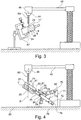
- the Fig. 2 shows a sketch of a blank 11 ', which at the passageways 27, 28, 23 and 24 by means of the manufacturing device FIGS. 5 and 6 was provided with markings in the form of conical depressions. The remaining markings at the passage points 12, 19, 20 and 13 are not shown.
- the blank 11 ' is clamped on the markings 23 and 24 between two pin tips 40 and 41 of a clamping device 42.
- the distance between the two pen tips 40 and 41 can be changed by moving the upper pen nib 40 and fixed by means of a locking nut 55.
- the upper pen nib 40 belongs to a continuous pin 43, which is clamped in a chuck 44 of a drilling device 45.
- the drilling device 45 may be a conventional parallel-milling device (parallelometer), which is suitable for vertical drilling.
- the blank 11 ' is fixed in position by means of a fixing device 47.
- the fixing device 47 has rubber jaws 48 and 49, which are elastic and, as in a screw clamp, by means of a handle 50 and the threaded screw 51, the blank 11 'clamp from both sides.
- the fixing device has a ball joint 52 and a stand 53 in order to adjust a movable tensioning rail 54 as desired.
- Fig. 3 the construction is shown as a method step based on the method step Fig. 2 follows.
- the Clamping device 42 off Fig. 2 was removed from the chuck 44 and replaced by a tool, namely a drill 60, wherein the blank 11 'is fixed in position by means of the fixing device 47 and the drilling axis 46 of the tool 60 coincides with the planned guide bore axis 8.
- the planned guide bore 4 between the markings 23 and 24 is made by means of the tool 60.
- the remaining scheduled guide bores 2, 3 and 5 are made in the same way by repeating the steps Fig.
- the drilling template 1 ' can be worked out of the blank, with markings 17, 18, 21, 22, 25, 26, 29 and 30 on the outer surfaces 15 and 16 of the drilling template in the form of depressions by means of the manufacturing device FIGS. 5 and 6 be attached. Thereafter, the marked drilling template 1 ', as in Fig. 2 and 3 shown clamped in the clamping device 42 between the respective markings of a bore, fixed with the fixing device 47 and carried out by means of the drilling device, the planned bore.
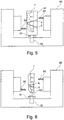
- FIG. 4 an alternative clamping device 70 is shown, which comprises a base 71, a first adjusting means 72 for adjusting an inclination angle 73, namely a rotary arm 74 which is rotatable about an axis 75 and with a locking nut 76 is adjustable.
- the tensioning device 70 has a second adjustment means for adjusting the angle of rotation, which is indicated by means of the rotation scale 84 is, wherein the adjusting means 75 has a receptacle 77 of the blank holder 78 which is rotatably arranged as an extension of the rotary arm 74 and the angle of rotation by means of a second locking screw 79 is fixed.
- the receptacle 77 has a pin 80 which engages in a groove on the blank holder 78 against rotation.
- the blank holder 78 is fixed in the receptacle 77 by means of a third adjusting nut 81.
- the tilt angle is displayed on the tilt scale 82.
- the base 71 is freely displaceable on the ground 83.
- the base 71 was moved on the substrate 83 so that the tool 60 of the drilling device 45 touches on the marking 27.
- the planned bore 5 was performed by means of the tool 60.
- the planned drilling template 1' is shown, which only after the implementation of all guide holes 2, 3, 4, 5 from the blank, as in FIGS. 5 and 6 represented by means of the manufacturing device FIGS. 5 and 6 is worked out.
- the indicated method steps must be repeated, namely setting the calculated angle of inclination 73 and the angle of rotation, the displacement of the base 71, so that the axis 46 of the tool 60 with the planned guide bore axis 9 for the guide hole.
- the clamping device according to Fig. 4 can also for the alternative inventive method used in the first step, the drilling template 1 'by means of the manufacturing device FIGS. 5 and 6 is worked out, wherein the upper and lower outer surface 15 and 16 of the drilling template is provided with markings as recesses, and only in the second step, the guide holes are performed on the marked drilling template.
- the drilling template which is as in Fig. 6 shown connected to the blank holder 78 remains clamped in the receptacle 77 and the base 71 is displaced so that the tool 60 touches on the corresponding upper mark.
- the planned guide bore is performed by means of the tool 60.
- the first adjustment means 72 and the second adjustment means 75 are designed so that the inclination angle between 0 ° and 90 ° and the rotation angle between 0 ° and 360 ° is adjustable.
- the Fig. 5 shows a sketch of a manufacturing device 90 in which the blank 11 'is clamped to the blank holder 78 in a socket 91.
- the planned drilling template 1 'according to the 3D drilling template model 1 is off Fig. 1 worked out in which the manufacturing device is controlled by a computer accordingly.
- the blank 11 ' is shown with manufactured guide holes 4 and 5, wherein the guide holes 4 and 5 after the first method Fig. 2 and 3 or by the second alternative method, as in Fig. 4 shown were produced.
- Fig. 6 is the finished Bohrschablohne 1 'shown with the guide holes 4 and 5 after the working out of the drilling template from the blank.
- the drilling template 1 ' remains with the blank holder 78 via a Connecting pin 100 is connected, which can be subsequently ground off the drill template 1 'manually.
- the blank 1 ' in the first step, is worked out from the blank 11' with markings at points of passage of the guide bore axes, the drilling template 1 'remaining connected to the blank holder 78 via the connecting pin. Only in the second step, the marked drilling template which is connected to the blank holder 78 in the clamping device according to Fig. 2 or after Fig. 4 clamped and the guide holes, as described performed.
Landscapes
- Health & Medical Sciences (AREA)
- Oral & Maxillofacial Surgery (AREA)
- Dentistry (AREA)
- Epidemiology (AREA)
- Life Sciences & Earth Sciences (AREA)
- Animal Behavior & Ethology (AREA)
- General Health & Medical Sciences (AREA)
- Public Health (AREA)
- Veterinary Medicine (AREA)
- Engineering & Computer Science (AREA)
- Physics & Mathematics (AREA)
- Theoretical Computer Science (AREA)
- Evolutionary Computation (AREA)
- Geometry (AREA)
- General Engineering & Computer Science (AREA)
- General Physics & Mathematics (AREA)
- Computer Hardware Design (AREA)
- Orthopedic Medicine & Surgery (AREA)
- Drilling And Boring (AREA)
- Perforating, Stamping-Out Or Severing By Means Other Than Cutting (AREA)
- Dental Prosthetics (AREA)
- Architecture (AREA)
- Software Systems (AREA)
- Dental Tools And Instruments Or Auxiliary Dental Instruments (AREA)
Applications Claiming Priority (2)
| Application Number | Priority Date | Filing Date | Title |
|---|---|---|---|
| DE102010031018A DE102010031018A1 (de) | 2010-07-06 | 2010-07-06 | Verfahren und Spannvorrichtung zur Herstellung einer zahnmedizinischen Bohrschablone |
| PCT/EP2011/061353 WO2012004282A1 (de) | 2010-07-06 | 2011-07-06 | Verfahren und spannvorrichtung zur herstellung einer zahnmedizinischen bohrschalone |
Publications (2)
| Publication Number | Publication Date |
|---|---|
| EP2590591A1 EP2590591A1 (de) | 2013-05-15 |
| EP2590591B1 true EP2590591B1 (de) | 2018-04-18 |
Family
ID=44629980
Family Applications (1)
| Application Number | Title | Priority Date | Filing Date |
|---|---|---|---|
| EP11741416.9A Not-in-force EP2590591B1 (de) | 2010-07-06 | 2011-07-06 | Verfahren zur herstellung einer zahnmedizinischen bohrschablone |
Country Status (8)
| Country | Link |
|---|---|
| US (1) | US9378308B2 (https=) |
| EP (1) | EP2590591B1 (https=) |
| JP (1) | JP5917505B2 (https=) |
| KR (1) | KR101780189B1 (https=) |
| BR (1) | BR112013000400B1 (https=) |
| CA (1) | CA2803537C (https=) |
| DE (1) | DE102010031018A1 (https=) |
| WO (1) | WO2012004282A1 (https=) |
Families Citing this family (16)
| Publication number | Priority date | Publication date | Assignee | Title |
|---|---|---|---|---|
| US20100192375A1 (en) | 2009-02-02 | 2010-08-05 | Remedent Nv | Method for producing a dentist tool |
| US8640338B2 (en) | 2009-02-02 | 2014-02-04 | Viax Dental Technologies, LLC | Method of preparation for restoring tooth structure |
| EP2739240B1 (en) | 2011-05-26 | 2020-07-15 | Viax Dental Technologies, Llc | Dental tool and guidance devices |
| EP2964128A1 (en) * | 2013-03-08 | 2016-01-13 | Trophy | Partial surgical guide |
| DE102013103209A1 (de) | 2013-03-28 | 2014-10-02 | Sicat Gmbh & Co. Kg | Verfahren zur Planung einer Wurzelkanalbehandlung eines Patienten |
| KR101478009B1 (ko) * | 2013-10-31 | 2015-01-02 | 연세대학교 산학협력단 | 악교정 수술용 상악 절단 가이드 템플릿 및 그 제작방법 |
| DE102014007870B4 (de) * | 2014-06-03 | 2017-03-02 | med.dent.minds GmbH | Verfahren und Rohlinge zur Herstellung einer zahnmedizinischen Bohrschablone |
| WO2016177381A2 (en) * | 2015-05-03 | 2016-11-10 | Khorshid Heba Ezzeldin Abdelrehim | A novel technique for computer aided surgical stents |
| JP6593180B2 (ja) * | 2016-01-08 | 2019-10-23 | 株式会社デンソー | 医療支援装置 |
| DE102016208794B3 (de) * | 2016-05-20 | 2017-10-05 | Sirona Dental Systems Gmbh | Computergestütztes Herstellungsverfahren für Zahnersatzteil oder dentales Hilfselement |
| DE102016221426A1 (de) * | 2016-10-31 | 2018-05-03 | Sirona Dental Systems Gmbh | Verfahren zur Planung einer dentalen Konstruktion |
| US11007035B2 (en) | 2017-03-16 | 2021-05-18 | Viax Dental Technologies Llc | System for preparing teeth for the placement of veneers |
| DE102018210259A1 (de) * | 2018-06-22 | 2019-12-24 | Sirona Dental Systems Gmbh | Verfahren zur Konstruktion einer Bohrschablone |
| EP3711707B1 (en) * | 2019-03-21 | 2022-01-19 | SIRONA Dental Systems GmbH | Relative orientation between coupled processing tools and blank bodies |
| US10959817B2 (en) | 2019-08-14 | 2021-03-30 | Sdc U.S. Smilepay Spv | Dental model holding system |
| KR102035758B1 (ko) * | 2019-09-19 | 2019-10-23 | 주식회사 임솔 | 임플란트 식립 가이드의 가공을 위한 지그 기구 |
Family Cites Families (29)
| Publication number | Priority date | Publication date | Assignee | Title |
|---|---|---|---|---|
| US1933718A (en) * | 1932-04-19 | 1933-11-07 | Albert A Devincenzi | Flexible vise |
| FR2446629A1 (fr) * | 1979-01-17 | 1980-08-14 | Laudy Jean | Paralleliseur |
| DE4328490A1 (de) * | 1993-08-25 | 1995-03-02 | Friedmann Leonid | Verfahren und Vorrichtung zur Lagebestimmung und präoperativen Ausrichtung von enossalen Implantaten im Kieferknochen und zum Setzen der Bohrungen für die Implantate |
| DE4334360A1 (de) * | 1993-10-08 | 1995-04-13 | Gamundia Dentalprodukte Und Cn | Bearbeitungstisch für Kiefermodelle |
| DE19629708C2 (de) * | 1996-07-24 | 1998-11-12 | Stephan Dr Dr Bonorden | Verfahren zur präoperativen Planung von Zahnimplantaten |
| US5876204A (en) * | 1997-11-25 | 1999-03-02 | Sulzer Calcitek Inc. | Dental implant positioning guide |
| ES2287389T3 (es) | 1997-12-18 | 2007-12-16 | Technique D'usinage Sinlab Inc. | Metodo de fabricacion de una guia de taladrado para implante dental. |
| US5927982A (en) * | 1998-09-29 | 1999-07-27 | Kruger; Bernard M. | Three dimensional guidance system for dental implant insertion |
| DE29817575U1 (de) * | 1998-10-01 | 1998-12-24 | Marburger Dental-Labor Jacob GmbH, 35041 Marburg | Vorrichtung zum Setzen und Korrigieren von Führungshülsen in Bohrschablonen für die dentale Implantologie |
| DE19952962B4 (de) | 1999-11-03 | 2004-07-01 | Sirona Dental Systems Gmbh | Verfahren zur Herstellung einer Bohrhilfe für ein Zahnimplantat |
| DE19959383C1 (de) | 1999-12-09 | 2001-04-12 | Gerd Neuschaefer | Vorrichtung zur Präparation mindestens eines Zahnes zur Aufnahme einer Krone, Brücke o. dgl. |
| US6527550B1 (en) * | 2000-02-15 | 2003-03-04 | Victor J. Hajjar | Apparatus and method for producing a dental prosthetic with a device having a linear rotary bearing |
| JP2003245289A (ja) * | 2002-02-22 | 2003-09-02 | Univ Nihon | 歯科用インプラント施術支援装置 |
| WO2003084426A1 (en) * | 2002-04-04 | 2003-10-16 | Akira Kitamura | Drill device for implanting |
| US7338283B2 (en) * | 2003-02-26 | 2008-03-04 | Dental Ventures Of America Inc. | Dental prostheses modeling system with symmetric double-well trays slidably mountable to articulator |
| WO2005023138A1 (en) * | 2003-09-04 | 2005-03-17 | Mjrad Co., Ltd. | Stent for guiding the location/direction of implant, and production method thereof |
| TWI276020B (en) | 2004-06-18 | 2007-03-11 | Hon Hai Prec Ind Co Ltd | Fiber display |
| EP1933757B1 (de) * | 2005-08-26 | 2017-03-29 | siCAT GmbH & Co. KG | Rohling als bohrschablone und zum registrieren von datensätzen |
| DE102005040739B4 (de) * | 2005-08-26 | 2019-06-06 | "Stiftung Caesar" (Center Of Advanced European Studies And Research) | Bohrschablone |
| JP5021660B2 (ja) * | 2005-10-24 | 2012-09-12 | バイオメット・3アイ・エルエルシー | 歯科用インプラント構成要素を製造するための方法 |
| US8043091B2 (en) * | 2006-02-15 | 2011-10-25 | Voxelogix Corporation | Computer machined dental tooth system and method |
| US7653455B2 (en) | 2006-07-28 | 2010-01-26 | 3M Innovative Properties Company | Computer-aided implanting of orthodontic anchorage devices using surgical guides |
| JP2008073440A (ja) * | 2006-09-25 | 2008-04-03 | Imagunooshisu Kk | インプラント植立ガイドの作製方法およびガイド用ブロック |
| AT506486B1 (de) | 2008-02-15 | 2013-03-15 | Steger Heinrich | Aufspannvorrichtung für eine rechnergesteuerte, spanabhebende bearbeitungsmaschine |
| ES2939259T3 (es) * | 2008-04-02 | 2023-04-20 | Neocis Llc | Sistema de implante dental guiado |
| US20090298008A1 (en) * | 2008-05-29 | 2009-12-03 | Ibur, L.L.C. | Dental x-ray and drill guide apparatus and method |
| JP2010142537A (ja) * | 2008-12-22 | 2010-07-01 | Yoshinari Umemura | 歯科インプラント手術用のサージカルガイド |
| US20110111362A1 (en) | 2009-11-11 | 2011-05-12 | Jerome Haber | Surgical guides |
| EP2525736A4 (en) * | 2010-01-22 | 2013-08-21 | Prec Through Imaging Llc | DENTAL IMPLANT SYSTEM AND METHOD |
-
2010
- 2010-07-06 DE DE102010031018A patent/DE102010031018A1/de not_active Ceased
-
2011
- 2011-07-06 JP JP2013517369A patent/JP5917505B2/ja not_active Expired - Fee Related
- 2011-07-06 KR KR1020137003051A patent/KR101780189B1/ko not_active Expired - Fee Related
- 2011-07-06 CA CA2803537A patent/CA2803537C/en not_active Expired - Fee Related
- 2011-07-06 BR BR112013000400-2A patent/BR112013000400B1/pt not_active IP Right Cessation
- 2011-07-06 WO PCT/EP2011/061353 patent/WO2012004282A1/de not_active Ceased
- 2011-07-06 EP EP11741416.9A patent/EP2590591B1/de not_active Not-in-force
- 2011-07-06 US US13/701,233 patent/US9378308B2/en not_active Expired - Fee Related
Non-Patent Citations (1)
| Title |
|---|
| None * |
Also Published As
| Publication number | Publication date |
|---|---|
| EP2590591A1 (de) | 2013-05-15 |
| KR101780189B1 (ko) | 2017-09-21 |
| DE102010031018A1 (de) | 2012-01-12 |
| BR112013000400B1 (pt) | 2020-01-07 |
| CA2803537A1 (en) | 2012-01-12 |
| WO2012004282A1 (de) | 2012-01-12 |
| US20130144417A1 (en) | 2013-06-06 |
| JP5917505B2 (ja) | 2016-05-18 |
| BR112013000400A2 (pt) | 2016-05-17 |
| JP2013529997A (ja) | 2013-07-25 |
| CA2803537C (en) | 2018-10-16 |
| KR20130128364A (ko) | 2013-11-26 |
| US9378308B2 (en) | 2016-06-28 |
Similar Documents
| Publication | Publication Date | Title |
|---|---|---|
| EP2590591B1 (de) | Verfahren zur herstellung einer zahnmedizinischen bohrschablone | |
| EP2670337B1 (de) | Bohrschablone für ein dentales implantat und ein verfahren zur herstellung dieser bohrschablone | |
| DE19952962B4 (de) | Verfahren zur Herstellung einer Bohrhilfe für ein Zahnimplantat | |
| DE602005002951T2 (de) | Massgefertigte implantierbare chirurgische führung und zugehöriges fräswerkzeug und herstellungsverfahren | |
| DE69724669T2 (de) | Verfahren zur herstellung einer zahnimplantatsuprastruktur | |
| DE10353913B4 (de) | Verfahren und Vorrichtung zum Herstellen einer navigierten Bohrschablone für die Einbringung von Zahnimplantatbohrungen | |
| EP3618752B1 (de) | Verfahren zur konstruktion einer bohrschablone | |
| DE102012011238B4 (de) | Verfahren zur Herstellung eines Laboranalogs für Dentalimplantate | |
| WO2009135513A1 (de) | Bearbeitungsvorrichtung zum anfertigen einer bohrschablone für zahnimplantate | |
| WO2010097405A1 (de) | Bohrschablone und verfahren zu deren herstellung | |
| WO2010085981A1 (de) | Okklusionsschablone | |
| DE4328490A1 (de) | Verfahren und Vorrichtung zur Lagebestimmung und präoperativen Ausrichtung von enossalen Implantaten im Kieferknochen und zum Setzen der Bohrungen für die Implantate | |
| DE19709215A1 (de) | Vorrichtung und System zur Herstellung einer Bohrschablone für Implantatzähne | |
| DE20205006U1 (de) | Handstück zur Befestigung von Markierungen | |
| DE19725197A1 (de) | Verfahren und Vorrichtung zur Lokalisierung von Zahnimplantaten sowie Vorrichtung zur Koordinatenzuordnung | |
| DE29817575U1 (de) | Vorrichtung zum Setzen und Korrigieren von Führungshülsen in Bohrschablonen für die dentale Implantologie | |
| DE19728865C2 (de) | Verfahren zur Plazierung von Dental-Implantaten | |
| EP1520551A2 (de) | Arbeitstisch für Zahntechniker und Zahnärzte | |
| EP3845197B1 (de) | Verfahren zum herstellen einer führungsschiene zur bearbeitung von prothesenzähnen | |
| DE10320709A1 (de) | Vorrichtung zum Handhaben eines in einen Knochen einzusetzenden Implantates, insbesondere eines Dentalimplantates | |
| DE1766012C3 (de) | Bohrlehre für zahnärztliche Zwecke und Verfahren zum Herstellen derselben | |
| DE19728864A1 (de) | Vorrichtung zur Bestimmung einer Plazierung von Dental-Implantaten im Kieferknochen | |
| WO2011131159A1 (de) | Set und verfahren zur herstellung wenigstens einer führungsbohrung in einer bohrschablone | |
| DE202010002180U1 (de) | Bohrhilfe zum Herstellen einer Kieferbohrung für ein Implantat |
Legal Events
| Date | Code | Title | Description |
|---|---|---|---|
| PUAI | Public reference made under article 153(3) epc to a published international application that has entered the european phase |
Free format text: ORIGINAL CODE: 0009012 |
|
| 17P | Request for examination filed |
Effective date: 20130103 |
|
| AK | Designated contracting states |
Kind code of ref document: A1 Designated state(s): AL AT BE BG CH CY CZ DE DK EE ES FI FR GB GR HR HU IE IS IT LI LT LU LV MC MK MT NL NO PL PT RO RS SE SI SK SM TR |
|
| DAX | Request for extension of the european patent (deleted) | ||
| GRAP | Despatch of communication of intention to grant a patent |
Free format text: ORIGINAL CODE: EPIDOSNIGR1 |
|
| INTG | Intention to grant announced |
Effective date: 20171031 |
|
| GRAS | Grant fee paid |
Free format text: ORIGINAL CODE: EPIDOSNIGR3 |
|
| GRAA | (expected) grant |
Free format text: ORIGINAL CODE: 0009210 |
|
| RBV | Designated contracting states (corrected) |
Designated state(s): AT CH DE FR GB IT LI |
|
| AK | Designated contracting states |
Kind code of ref document: B1 Designated state(s): AT CH DE FR GB IT LI |
|
| REG | Reference to a national code |
Ref country code: GB Ref legal event code: FG4D Free format text: NOT ENGLISH |
|
| REG | Reference to a national code |
Ref country code: CH Ref legal event code: EP |
|
| REG | Reference to a national code |
Ref country code: AT Ref legal event code: REF Ref document number: 989601 Country of ref document: AT Kind code of ref document: T Effective date: 20180515 |
|
| REG | Reference to a national code |
Ref country code: DE Ref legal event code: R096 Ref document number: 502011014068 Country of ref document: DE |
|
| REG | Reference to a national code |
Ref country code: FR Ref legal event code: PLFP Year of fee payment: 8 |
|
| REG | Reference to a national code |
Ref country code: DE Ref legal event code: R097 Ref document number: 502011014068 Country of ref document: DE |
|
| PLBE | No opposition filed within time limit |
Free format text: ORIGINAL CODE: 0009261 |
|
| STAA | Information on the status of an ep patent application or granted ep patent |
Free format text: STATUS: NO OPPOSITION FILED WITHIN TIME LIMIT |
|
| 26N | No opposition filed |
Effective date: 20190121 |
|
| REG | Reference to a national code |
Ref country code: DE Ref legal event code: R082 Ref document number: 502011014068 Country of ref document: DE |
|
| PGFP | Annual fee paid to national office [announced via postgrant information from national office to epo] |
Ref country code: IT Payment date: 20210610 Year of fee payment: 11 Ref country code: FR Payment date: 20210611 Year of fee payment: 11 |
|
| PGFP | Annual fee paid to national office [announced via postgrant information from national office to epo] |
Ref country code: GB Payment date: 20210609 Year of fee payment: 11 |
|
| PGFP | Annual fee paid to national office [announced via postgrant information from national office to epo] |
Ref country code: AT Payment date: 20210625 Year of fee payment: 11 |
|
| PGFP | Annual fee paid to national office [announced via postgrant information from national office to epo] |
Ref country code: DE Payment date: 20210608 Year of fee payment: 11 Ref country code: CH Payment date: 20210715 Year of fee payment: 11 |
|
| REG | Reference to a national code |
Ref country code: DE Ref legal event code: R119 Ref document number: 502011014068 Country of ref document: DE |
|
| REG | Reference to a national code |
Ref country code: CH Ref legal event code: PL |
|
| REG | Reference to a national code |
Ref country code: AT Ref legal event code: MM01 Ref document number: 989601 Country of ref document: AT Kind code of ref document: T Effective date: 20220706 |
|
| GBPC | Gb: european patent ceased through non-payment of renewal fee |
Effective date: 20220706 |
|
| PG25 | Lapsed in a contracting state [announced via postgrant information from national office to epo] |
Ref country code: LI Free format text: LAPSE BECAUSE OF NON-PAYMENT OF DUE FEES Effective date: 20220731 Ref country code: FR Free format text: LAPSE BECAUSE OF NON-PAYMENT OF DUE FEES Effective date: 20220731 Ref country code: CH Free format text: LAPSE BECAUSE OF NON-PAYMENT OF DUE FEES Effective date: 20220731 Ref country code: AT Free format text: LAPSE BECAUSE OF NON-PAYMENT OF DUE FEES Effective date: 20220706 |
|
| PG25 | Lapsed in a contracting state [announced via postgrant information from national office to epo] |
Ref country code: GB Free format text: LAPSE BECAUSE OF NON-PAYMENT OF DUE FEES Effective date: 20220706 Ref country code: DE Free format text: LAPSE BECAUSE OF NON-PAYMENT OF DUE FEES Effective date: 20230201 |
|
| PG25 | Lapsed in a contracting state [announced via postgrant information from national office to epo] |
Ref country code: IT Free format text: LAPSE BECAUSE OF NON-PAYMENT OF DUE FEES Effective date: 20220706 |