EP2590318A2 - Dispositif d'actionnement linéaire - Google Patents
Dispositif d'actionnement linéaire Download PDFInfo
- Publication number
- EP2590318A2 EP2590318A2 EP11801006.5A EP11801006A EP2590318A2 EP 2590318 A2 EP2590318 A2 EP 2590318A2 EP 11801006 A EP11801006 A EP 11801006A EP 2590318 A2 EP2590318 A2 EP 2590318A2
- Authority
- EP
- European Patent Office
- Prior art keywords
- moving element
- amplitude
- driving command
- movable
- reciprocation
- Prior art date
- Legal status (The legal status is an assumption and is not a legal conclusion. Google has not performed a legal analysis and makes no representation as to the accuracy of the status listed.)
- Withdrawn
Links
- 238000006073 displacement reaction Methods 0.000 claims abstract description 29
- 230000004044 response Effects 0.000 claims abstract description 18
- 230000000875 corresponding effect Effects 0.000 claims description 20
- 230000002596 correlated effect Effects 0.000 claims description 10
- 238000013016 damping Methods 0.000 description 16
- 238000004364 calculation method Methods 0.000 description 15
- 230000006870 function Effects 0.000 description 7
- 230000001133 acceleration Effects 0.000 description 5
- 238000001514 detection method Methods 0.000 description 5
- 238000010586 diagram Methods 0.000 description 5
- 230000007246 mechanism Effects 0.000 description 5
- 230000004907 flux Effects 0.000 description 4
- 230000005484 gravity Effects 0.000 description 4
- 230000000694 effects Effects 0.000 description 3
- 230000001771 impaired effect Effects 0.000 description 2
- 238000000034 method Methods 0.000 description 2
- 230000009467 reduction Effects 0.000 description 2
- 239000006096 absorbing agent Substances 0.000 description 1
- 238000004519 manufacturing process Methods 0.000 description 1
- 230000002265 prevention Effects 0.000 description 1
Images



Classifications
-
- H—ELECTRICITY
- H02—GENERATION; CONVERSION OR DISTRIBUTION OF ELECTRIC POWER
- H02P—CONTROL OR REGULATION OF ELECTRIC MOTORS, ELECTRIC GENERATORS OR DYNAMO-ELECTRIC CONVERTERS; CONTROLLING TRANSFORMERS, REACTORS OR CHOKE COILS
- H02P21/00—Arrangements or methods for the control of electric machines by vector control, e.g. by control of field orientation
- H02P21/22—Current control, e.g. using a current control loop
-
- B—PERFORMING OPERATIONS; TRANSPORTING
- B60—VEHICLES IN GENERAL
- B60N—SEATS SPECIALLY ADAPTED FOR VEHICLES; VEHICLE PASSENGER ACCOMMODATION NOT OTHERWISE PROVIDED FOR
- B60N2/00—Seats specially adapted for vehicles; Arrangement or mounting of seats in vehicles
- B60N2/02—Seats specially adapted for vehicles; Arrangement or mounting of seats in vehicles the seat or part thereof being movable, e.g. adjustable
- B60N2/0224—Non-manual adjustments, e.g. with electrical operation
- B60N2/0244—Non-manual adjustments, e.g. with electrical operation with logic circuits
- B60N2/0277—Non-manual adjustments, e.g. with electrical operation with logic circuits characterised by the calculation method or calculation flow chart of sensor data for adjusting the seat
-
- F—MECHANICAL ENGINEERING; LIGHTING; HEATING; WEAPONS; BLASTING
- F16—ENGINEERING ELEMENTS AND UNITS; GENERAL MEASURES FOR PRODUCING AND MAINTAINING EFFECTIVE FUNCTIONING OF MACHINES OR INSTALLATIONS; THERMAL INSULATION IN GENERAL
- F16F—SPRINGS; SHOCK-ABSORBERS; MEANS FOR DAMPING VIBRATION
- F16F7/00—Vibration-dampers; Shock-absorbers
- F16F7/10—Vibration-dampers; Shock-absorbers using inertia effect
- F16F7/1005—Vibration-dampers; Shock-absorbers using inertia effect characterised by active control of the mass
- F16F7/1011—Vibration-dampers; Shock-absorbers using inertia effect characterised by active control of the mass by electromagnetic means
-
- H—ELECTRICITY
- H02—GENERATION; CONVERSION OR DISTRIBUTION OF ELECTRIC POWER
- H02P—CONTROL OR REGULATION OF ELECTRIC MOTORS, ELECTRIC GENERATORS OR DYNAMO-ELECTRIC CONVERTERS; CONTROLLING TRANSFORMERS, REACTORS OR CHOKE COILS
- H02P21/00—Arrangements or methods for the control of electric machines by vector control, e.g. by control of field orientation
- H02P21/05—Arrangements or methods for the control of electric machines by vector control, e.g. by control of field orientation specially adapted for damping motor oscillations, e.g. for reducing hunting
-
- H—ELECTRICITY
- H02—GENERATION; CONVERSION OR DISTRIBUTION OF ELECTRIC POWER
- H02P—CONTROL OR REGULATION OF ELECTRIC MOTORS, ELECTRIC GENERATORS OR DYNAMO-ELECTRIC CONVERTERS; CONTROLLING TRANSFORMERS, REACTORS OR CHOKE COILS
- H02P25/00—Arrangements or methods for the control of AC motors characterised by the kind of AC motor or by structural details
- H02P25/02—Arrangements or methods for the control of AC motors characterised by the kind of AC motor or by structural details characterised by the kind of motor
- H02P25/032—Reciprocating, oscillating or vibrating motors
-
- B—PERFORMING OPERATIONS; TRANSPORTING
- B60—VEHICLES IN GENERAL
- B60N—SEATS SPECIALLY ADAPTED FOR VEHICLES; VEHICLE PASSENGER ACCOMMODATION NOT OTHERWISE PROVIDED FOR
- B60N2210/00—Sensor types, e.g. for passenger detection systems or for controlling seats
-
- B—PERFORMING OPERATIONS; TRANSPORTING
- B60—VEHICLES IN GENERAL
- B60N—SEATS SPECIALLY ADAPTED FOR VEHICLES; VEHICLE PASSENGER ACCOMMODATION NOT OTHERWISE PROVIDED FOR
- B60N2230/00—Communication or electronic aspects
- B60N2230/30—Signal processing of sensor data
Definitions
- the present invention relates to a driving device of a linear actuator in which a moving element is made to reciprocate. More particularly, the present invention relates to a driving device of a linear actuator in which offset displacement of the driving element is properly corrected if offset displacement of the moving element has occurred due to self weight and a movable range thereof has become narrower than its original movable range.
- a linear actuator driving device such as a reciprocal motor
- a linear actuator driving device is a device also called “driver” which causes a moving element to reciprocate electrically by carrying out energization in response to a driving command.
- the linear actuator such as a reciprocal motor
- the linear actuator there is a case in which, in a non-energized state, the center of reciprocation of the moving element is displaced from the center of a predetermined movement possible range due to self weight and, therefore, the movable range becomes narrower than the original movement possible range.
- Patent Document 1 discloses a device for electrically correcting offset displacement of a movable element by constantly carrying out offset energization: the disclosed device includes an offset correcting unit which corrects a driving command such that offset energization is carried out to cause the center of reciprocation of the moving element to move in a direction in which deviation between the center of reciprocation of the moving element and the center of a movement possible range is eliminated.
- Patent Documents 2 and 3 disclose devices for mechanically correcting offset displacement: in the disclosed devices, arrangement positions of permanent magnets are determined or strength of each permanent magnet is varied such that deviation is caused in magnetic fluxes of the permanent magnets in a non-energized state.
- the present invention is made in view of these problems, and an object thereof is to provide a novel linear actuator driving device which has achieved power saving in correcting offset displacement produced due to self weight of the moving element without any increase in device size and with reduced power consumption.
- a linear actuator driving device of the present invention includes: an electromagnetic driving unit which makes a moving element reciprocate by carrying out energization in response to a driving command and; an offset correcting unit which corrects the driving command to carry out offset energization to make the center of reciprocation of the moving element be moved in the direction in which deviation between the center of reciprocation of the moving element and the center of a movement possible range is eliminated in a case in which, in a non-energized state, the moving element is displaced from the center of the predetermined movement possible range due to self weight and, therefore, the movable range is narrower than the movement possible range, wherein the offset correcting unit acquires amplitude information corresponding to an amplitude value of the moving element required for the reciprocation in response to the driving command and, if a movable amplitude with respect to an amplitude value corresponding to the acquired amplitude information is in a movable area insufficient condition, performs correction of the driving command and, on the other hand, if the movable
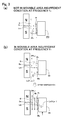
- the movable area insufficient condition includes not only a condition that the movable amplitude is insufficient for the amplitude value of the moving element necessary for the reciprocation in response to the driving command, but also a condition that a predetermined margin is not included even if the movable amplitude is sufficient for the amplitude value of the moving element necessary for the reciprocation in response to the driving command.
- the movable amplitude is half the length of the movable range.
- the amplitude information corresponding to an amplitude value of the moving element required for reciprocation in response to the driving command is acquired and, with respect to the amplitude value corresponding to the acquired amplitude information, if movable amplitude is in a movable area insufficient condition, correction of the driving command is performed and offset energization is carried out and, on the other hand, if the movable amplitude is not in the movable area insufficient condition, correction of the driving command is released and offset energization is stopped.
- the offset correcting unit is configured to acquire frequency related to reciprocation of the moving element as amplitude information and acquire an amplitude value of the moving element from the acquired frequency and the maximum value which the driving command can take under the frequency.
- the offset correcting unit is configured to acquire frequency and the driving command related to reciprocation of the moving element as the amplitude information and acquire the amplitude value of the moving element from the acquired frequency and a value of the driving command.
- the offset correcting unit corrects the driving command such that the center of reciprocation of the moving element is moved by insufficient distance of movable amplitude which is determined from an amplitude value corresponding to the amplitude information, a previously set movement possible range and from an amount of offset displacement.
- the offset correcting unit corrects the driving command such that the center of reciprocation of the movable element is moved by certain distance.
- the offset correcting unit In order to implement the offset correcting unit with a simple configuration, it is desirable that the offset correcting unit previously stores correction information in which a correction amount by which the center of reciprocation of the moving element is moved by the offset energization and the amplitude information are correlated with each other and corrects the driving command using the correction amount correlated with the amplitude information in the correction information.
- the driving command is corrected and offset energization is carried out such that the center of reciprocation of the moving element is moved in the direction in which deviation between the center of reciprocation of the moving element and the center of the movement possible range is eliminated and, on the other hand, if the movable amplitude is not in the movable area insufficient condition, correction of the driving command is released and offset energization is stopped, it is possible to reduce offset energization compared with the case in which offset energization is carried out constantly irrespective of whether the movable amplitude is not in the movable area insufficient condition as in the related art, to achieve power saving, and to improve power efficiency. Further, since the offset displacement of the
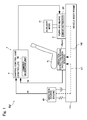
- the linear actuator driving device 1 is, as illustrated in Figs. 1 and 2 , a device which is applied to a damping system sy which reduces vibration at a position pos at which damping should be performed by causing vibration Vi1 generated in a vibration source gn and cancelling vibration Vi2 which is to be generated, via a vibrating means 2, at a position pos at which damping should be performed to be cancelled at a position pos at which damping should be performed, and which makes a moving element 23 of a linear actuator 20 used as the vibrating means 2 reciprocate.
- the damping system sy to which the linear actuator driving device 1 of the present embodiment is applied, as illustrated in Fig. 1 , is mounted on a vehicle, such as a car.
- the damping system sy includes a vibration detecting unit 3, such as an acceleration sensor, provided at the position pos at which damping should be performed, such as a seat st, and a control unit 4 (also referred to as "controller") which performs damping control to make the vibrating means 2 generate appropriate canceling vibration Vi2 such that vibration detected by the vibration detecting unit 3 is small.
- the control unit 4 includes, as a main component, a damping algorithm unit 4a which inputs an ignition pulse signal sh of an engine which is the vibration source gn and a detection signal sg from the vibration detecting unit 3 and generates a driving command which is a command to instruct the vibrating means 2 to generate the cancelling vibration Vi2 on the basis of these signals sh and sg.
- a damping algorithm unit 4a which inputs an ignition pulse signal sh of an engine which is the vibration source gn and a detection signal sg from the vibration detecting unit 3 and generates a driving command which is a command to instruct the vibrating means 2 to generate the cancelling vibration Vi2 on the basis of these signals sh and sg.
- the linear actuator driving device 1 includes, as a main component, an electromagnetic driving unit 10 which makes the moving element 23 of the linear actuator 20 reciprocate by inputting a driving command Iref which is generated by the damping algorithm unit 4a, and making energization in accordance with the driving command Iref be applied to a coil (not illustrated) which constitutes the linear actuator 20.
- the linear actuator driving device 1 is provided in the control unit 4 (i.e., the controller). Since a specific configuration and explanation of operation of the electromagnetic driving unit 10 itself have been publicly known, as disclosed in, for example, Patent Document 1, detailed description thereof will be omitted.
- the linear actuator 20 to be driven is, as illustrated in Fig. 2 , an inner reciprocating type linear actuator in which a stator 22 provided with permanent magnets is fixed to a vehicle body frame frm and the moving element 23 is made to reciprocate (i.e., perform an up-and-down movement on the page of Fig. 2 ) in the same direction as the direction of the vibration in which damping should be performed.
- the linear actuator 20 is fixed to the vehicle body frame frm such that the direction of the vibration, in which damping should be performed, of the vehicle body frame frm and the reciprocating direction (i.e., the thrust direction) of the moving element 23 coincide with each other.
- the moving element 23 is attached to an axis 25 together with auxiliary mass 21.
- the axis 25 is supported by the stator 22 via a flat spring 24 so that the moving element 23 and the auxiliary mass 21 are movable in the thrust direction.
- a dynamic vibration absorber is thus constituted by the linear actuator 20 and the auxiliary mass 21.
- an alternating current i.e., an sinusoidal current, a square wave current
- the coil which constitutes the linear actuator 20
- a current in a predetermined direction is applied to the coil
- magnetic fluxes are guided from S poles to N poles of the permanent magnets and thus a magnetic flux loop is formed. Therefore, the moving element 23 is moved in a direction opposing the gravity (i.e., upward).
- the moving element 23 is moved in the gravity direction (i.e., downward).
- the moving element 23 repeats the above-described movement as the direction of the current flow of the alternating current in the coil is changed alternately and reciprocates in the axial direction of the axis 25 with respect to the stator 22. Therefore, the auxiliary mass 21 attached to the axis 25 vibrates in the up-down direction. Since a specific configuration and explanation of operation of the linear actuator 20 itself have been publicly known, as disclosed in, for example, Patent Document 1, detailed description thereof will be omitted.
- a predetermined movement possible range D of the moving element 23 is defined by a stopper, not illustrated, which regulates an operating range.
- the movable range of the moving element 23 is the maximum.
- the present embodiment further includes, as illustrated in Fig. 2 , an offset correcting unit 11 which corrects the driving command Iref to carry out offset energization to make the center of reciprocation Wc of the moving element 23 be moved in the direction in which deviation between the center of reciprocation Wc of the moving element 23 and the center Dc of the movement possible range D is eliminated.
- an offset correcting unit 11 which corrects the driving command Iref to carry out offset energization to make the center of reciprocation Wc of the moving element 23 be moved in the direction in which deviation between the center of reciprocation Wc of the moving element 23 and the center Dc of the movement possible range D is eliminated.
- the offset correcting unit 11 is configured such that amplitude information corresponding to an amplitude value Lp of the moving element 23 required for reciprocation in response to the driving command Iref is acquired and, with respect to the amplitude value Lp corresponding to the acquired amplitude information, if the movable amplitude (W 1 /2) is in a movable area insufficient condition, correction of the driving command Iref is performed and, on the other hand, if the movable amplitude is not in the movable area insufficient condition, correction of the driving command Iref is released.
- the offset correcting unit 11 is configured to include a frequency acquisition unit 12 and a driving command correction unit 13.
- the frequency acquisition unit 12 acquires, as amplitude information, frequency f applied to the reciprocation of the moving element 23.
- the amplitude information is information which corresponds to the amplitude value Lp of the moving element 23 required for the reciprocation in response to the driving command Iref.
- the amplitude information is the information representing the amplitude value Lp of the moving element 23 itself or an element which is a base for the acquisition of the amplitude value Lp of the moving element 23.
- Examples of the element which is the base for the acquisition of the amplitude value Lp of the moving element 23 are the frequency f related to the reciprocation of the moving element 23 and the value of the driving command Iref.
- the amplitude value Lp of the moving element 23 can be determined (i.e., calculated) on the basis of two parameters of the frequency f related to the value of the driving command Iref and the reciprocation of the moving element 23.
- the frequency of the vibration Vi1 generated in the vibration source gn on the basis of the ignition pulse signal sh of the engine which is the vibration source gn is detected and the detected frequency is handled as the frequency f related to the reciprocation of the moving element 23.
- the driving command correction unit 13 previously stores, in memory Me, correction information 14 in which the correction amount Id by which the center of reciprocation Wc of the moving element 23 is moved by offset energization and the frequency f which is the amplitude information are correlated with each other.
- the driving command correction unit 13 corrects the driving command Iref using the correction amount Id correlated with the frequency f acquired by the frequency acquisition unit 12 from among the correction information 14.
- the driving command correction unit 13 acquires a corresponding correction amount Id from among the correction information 14 with the frequency f acquired in the frequency acquisition unit 12 as a key and adds the correction amount Id to the driving command Iref in an adder 13a.
- the driving command correction unit 13 corrects the driving command Iref to carry out offset energization to make the center of reciprocation Wc of the moving element 23 be moved in the direction in which deviation between the center of reciprocation Wc of the moving element 23 and the center Dc of the movement possible range D is eliminated.
- the correction amount Id are the distance itself by which the center of reciprocation Wc of the moving element 23 is moved and a current value as an amount for correcting the driving command, the correction amount Id is handled as the current value for correcting the driving command in the present embodiment.
- the correction information 14 is generated by performing each of steps S1 to S5 illustrated in Fig. 4 . That is, a driving command calculation step S1 for calculating a driving command that becomes the maximum under a certain frequency is performed; an amplitude value acquisition step S2 for acquiring an amplitude value of the moving element from a value of the driving command and frequency is performed; an insufficient distance calculation step S3 for calculating insufficient distance in accordance with insufficiency of the movable amplitude from the acquired amplitude value of the moving element, a previously set movement possible range and an amount of offset displacement is performed; a correction amount calculation step S4 for calculating a correction amount of the driving command for making the center of reciprocation of the moving element be moved by the insufficient distance is performed; and a storage step S5 for correlating the calculated correction amount and the frequency with each other and storing as the correction information 14 is performed.
- steps S1 to S5 are performed as a series of process steps for each frequency to generate the correction information 14.
- the driving command may be described as a driving current command in which a current is used, but the driving command may be handled as a driving voltage command in which voltage is used.
- the driving command Iref (i.e., the driving current command) which becomes the maximum under a certain frequency is calculated.
- the value of the driving current command Iref which becomes the maximum the smallest value from among a motor maximum current Ic (i.e., the maximum output value), a position maximum current Ip (i.e., collision avoidance), or a voltage maximum current Iv (i.e., voltage saturation prevention) illustrated in Fig. 5 is employed.
- the motor maximum current Ic illustrated in Fig. 5 is either the smaller of the maximum current value which can be output in the control unit 4 (i.e., the controller) illustrated in Fig. 2 which embodies an arithmetic processing function of the present embodiment or the maximum current which can be applied through the linear actuator 20 (i.e., the current strong enough not to demagnetize the magnets) and is constant irrespective of the frequency.
- the position maximum current Ip illustrated in Fig. 5 is the upper limit value of the current with which the moving element 23 which operates, when energized with a sinusoidal current, does not move out of the movement possible range D.
- Position maximum current Ip f ⁇ 2 ⁇ Lmax / G f
- the voltage maximum current Iv illustrated in Fig. 5 is the upper limit of the current with which voltage saturation, which is a phenomenon that as the frequency becomes large, it becomes difficult to apply a current due to induced voltage of a reciprocal motor, is not caused although the voltage saturation is caused as the frequency becomes large.
- the amplitude value Lp of the moving element 23 is calculated from the value of the driving command Iref (i.e., the driving current command) and the frequency f. That is, formula 7 is acquired from the following formulae (3) to (6) when the motor thrust constant is kt, peak acceleration is Ap, and effective acceleration is a with respect to the driving command Iref(f), and an amplitude value Lp(f) of the moving element is acquired by inputting the frequency f and the driving command Iref(f) into formula (7).
- insufficient distance Lc of the moving amplitude (W 1 /2) is calculated from an amplitude value Lp(f) of the moving element 23, a previously set acceptable amplitude value Lmax (which is half the length of the movement possible range D), and the amount of offset displacement Lm.
- Amount of offset displacement: Lm m ⁇ g/k
- Lc Lmax-Lm-Lp(f) where m represents the mass of the moving element, g represents the gravity acceleration and k represents the spring constant of the actuator.
- correction amount Id of the driving command Iref for making the center of reciprocation Wc of the moving element 23 to be moved by the insufficient distance Lc described above is calculated.
- the correction amount Id of the driving command Iref is calculated by the following formula.
- Correction amount Id k ⁇ Lc / kt where k represents a spring constant of the spring which constitutes the actuator and kt represents the motor thrust constant.
- the correction amount for the correction of the driving command Iref is Id 1 (Id 1 >0). Since the correction information 14 in which the frequency f 1 and the correction amount Id 1 are correlated with each other is used as illustrated in Fig.
- the correction amount Id 1 is acquired with a simple configuration without providing, for example, a mechanism for calculating the amplitude value Lp and the insufficient distance Lc of the moving element 23 on a real-time basis and a mechanism for determining whether the movable amplitude is in the movable area insufficient condition
- the linear actuator driving device 1 of the present embodiment includes the electromagnetic driving unit 10 which makes the moving element 23 reciprocate by carrying out energization in response to the driving command Iref and the offset correcting unit 11 which corrects the driving command Iref to carry out offset energization to make the center of reciprocation Wc of the moving element 23 be moved in the direction in which deviation between the center of reciprocation Wc of the moving element 23 and the center Dc of the movement possible range D is eliminated in a case in which, in a non-energized state, the moving element 23 is displaced from the center Dc of the predetermined movement possible range D due to self weight and, therefore, the movable range W 1 is narrower than the movement possible range D.
- the offset correcting unit 11 is configured such that the amplitude information corresponding to an amplitude value Lp of the moving element 23 required for reciprocation in response to the driving command Iref is acquired and, with respect to the amplitude value Lp corresponding to the acquired amplitude information, if the movable amplitude (W 1 /2) is in a movable area insufficient condition, correction of the driving command Iref is performed and, on the other hand, if the movable amplitude is not in the movable area insufficient condition, correction of the driving command Iref is released.
- the amplitude information corresponding to an amplitude value Lp of the moving element 23 required for reciprocation in response to the driving command Iref is acquired and, with respect to the amplitude value Lp corresponding to the acquired amplitude information, if the movable amplitude (W 1 /2) is in a movable area insufficient condition, the driving command Iref is corrected and offset energization is carried out and, on the other hand, if the movable amplitude is not in the movable area insufficient condition, the correction of the driving command Iref is released and offset energization is stopped.
- the offset correcting unit 11 is configured to acquire, in the frequency acquisition unit 12, the frequency f related to the reciprocation of the moving element 23 as the amplitude information and to acquire the amplitude value Lp of the moving element 23 from the acquired frequency f and the maximum value which the driving command Iref can take under the frequency f, it is possible to configure that the driving command Iref is uniformly considered to be the maximum and the amplitude value Lp of the moving element 23 is acquired in accordance with the frequency f of a single parameter, whereby the device is simplified. Especially, since the amplitude value Lp becomes small as the frequency becomes large, it is possible to effectively achieve an effect of reducing power consumption at high frequencies.
- the offset correcting unit 11 corrects the driving command Iref such that the center of reciprocation Wc of the moving element 23 is moved by the distance Lc in accordance with the insufficiency of the movable range W 1 determined by the amplitude value Lp corresponding to the amplitude information, the previously set movement possible range D and the amount of offset displacement Lm, the offset energization can be reduced to the limit necessary to secure the movable range required for the reciprocation of the moving element 23. Therefore, it is possible to further pursue power saving.
- the offset correcting unit 11 previously stores, the correction information 14 in which the correction amount Id by which the center of reciprocation Wc of the moving element 23 is moved by offset energization and the frequency f which is the amplitude information are correlated with each other and corrects the driving command Iref using the correction amount Id related to the frequency f which is the amplitude information in the correction information 14.
- the offset correcting unit 11 described above can be implemented with a simple configuration while omitting, for example, a mechanism for calculating the amplitude value Lp and the insufficient distance Lc of the moving element 23 on a real-time basis and a mechanism for determining whether the movable amplitude is in the movable area insufficient condition, and with reduced manufacturing cost.
- an offset correcting unit 111 is configured to include a frequency acquisition unit 12 which is the same in configuration as that described above, and a newly provided offset correction amount calculating unit 113.
- the offset correction amount calculating unit 113 corrects the driving command Iref by acquiring frequency f related to the reciprocation of the moving element 23 acquired in the frequency acquisition unit 12 as amplitude information, acquiring a driving command Iref produced by a damping algorithm unit 4a as amplitude information, acquiring an amplitude value Lp of the moving element 23 from a value of the acquired frequency f and the driving command Iref through calculation, calculating insufficient distance Lc on the basis of the acquired amplitude value Lp, and adding a correction amount Id in accordance with the insufficient distance Lc in the adder 113a. This calculation is performed using each calculation formula described in the amplitude value acquisition step S2, the insufficient distance calculation step S3 and the correction amount calculation step S4.
- the amplitude value Lp of the moving element 23 is calculated on the basis of the driving command Iref which is actually used in driving the actuator 20, it is possible to carry out highly accurate offset energization using the actual amplitude value of the moving element compared with a case in which an amplitude value of the moving element obtained on the assumption that the driving command is always the maximum as in the present embodiment. Especially, it is possible to effectively achieve an effect of reducing power consumption if the amplitude value of the moving element is small at not only high frequencies but also low frequencies.
- an offset correcting unit 211 is constituted by a frequency acquisition unit 12 which is the same in configuration as that described above, an amplitude calculating unit 213, a determining unit 214 and a selecting unit 215.
- the amplitude calculating unit 213 acquires frequency f related to reciprocation of the moving element 23 acquired in the frequency acquisition unit 12 as amplitude information, acquires a driving command Iref produced in a damping algorithm unit 4a as amplitude information, and calculates the amplitude value Lp of the moving element 23 using a calculation formula, described in the amplitude value acquisition step S2, from the acquired frequency f and the value of the driving command Iref.
- the determining unit 214 determines whether the movable amplitude is in a movable area insufficient condition (i.e., in a collision risk condition) on the basis of the amplitude value Lp calculated in the amplitude calculating unit 213 and inputs a determination result signal sa in the selecting unit 215.
- the determining unit 214 compares a movable amplitude to which a margin is given by multiplication of a movable amplitude (W 1 /2) narrowed due to offset displacement (i.e., acceptable amplitude value Lmax - amount of offset displacement Lm) by a margin coefficient 0.8 in a multiplier 214a with the calculated amplitude value Lp and, if the amplitude value Lp is larger, determines that the movable amplitude is in the movable area insufficient condition (i.e., the collision risk condition).
- the movable amplitude (W 1 /2) is (acceptable amplitude value Lmax - amount of offset displacement Lm).
- the selecting unit 215 sets a correction amount Id to 0.
- the selecting unit 215 corrects the driving command Iref by adding the correction amount Id in the adder 213a with the correction amount Id being a predetermined fixed amount Id f .
- the predetermined fixed amount Id f is set such that, for example, the center of reciprocation Wc of the moving element 23 is moved by, for example, an amount of offset displacement Lm.
- the driving command Iref constituted by a current has been exemplified in the embodiment described above, the driving command Iref constituted by voltage is applicable similarly.
- an inner type linear actuator has been exemplified in the present embodiment, the present embodiment is applicable also to an outer type linear actuator.
- the linear actuator driving device 1 is applied to the damping system sy as the vibrating means 2 in the present embodiment, the linear actuator driving device 1 is applicable to other devices or systems which drive a linear actuator.
- Each function unit illustrated in Figs. 2 , 6 and 7 may be implemented by execution of predetermined programs by a processor, or each function unit may be constituted by a dedicated circuit.
- a position detection sensor which detects position of the moving element as amplitude information and acquire the amplitude value of the moving element on the basis of the detection result of the position detection sensor.
- the position detection sensor are a shielding sensor and a displacement sensor.
Landscapes
- Engineering & Computer Science (AREA)
- Power Engineering (AREA)
- General Engineering & Computer Science (AREA)
- Mechanical Engineering (AREA)
- Physics & Mathematics (AREA)
- Electromagnetism (AREA)
- Aviation & Aerospace Engineering (AREA)
- Transportation (AREA)
- Control Of Linear Motors (AREA)
- Vibration Prevention Devices (AREA)
Applications Claiming Priority (2)
| Application Number | Priority Date | Filing Date | Title |
|---|---|---|---|
| JP2010152431A JP5569195B2 (ja) | 2010-07-02 | 2010-07-02 | リニアアクチュエータ駆動装置 |
| PCT/JP2011/065217 WO2012002544A2 (fr) | 2010-07-02 | 2011-07-01 | Dispositif d'actionnement linéaire |
Publications (1)
| Publication Number | Publication Date |
|---|---|
| EP2590318A2 true EP2590318A2 (fr) | 2013-05-08 |
Family
ID=45402499
Family Applications (1)
| Application Number | Title | Priority Date | Filing Date |
|---|---|---|---|
| EP11801006.5A Withdrawn EP2590318A2 (fr) | 2010-07-02 | 2011-07-01 | Dispositif d'actionnement linéaire |
Country Status (5)
| Country | Link |
|---|---|
| US (1) | US8912737B2 (fr) |
| EP (1) | EP2590318A2 (fr) |
| JP (1) | JP5569195B2 (fr) |
| CN (1) | CN103038998B (fr) |
| WO (1) | WO2012002544A2 (fr) |
Families Citing this family (8)
| Publication number | Priority date | Publication date | Assignee | Title |
|---|---|---|---|---|
| CN103754678B (zh) * | 2014-01-28 | 2017-01-04 | 杭州登新科技有限公司 | 贴片机编带进料装置及贴片机 |
| JP6308852B2 (ja) * | 2014-04-15 | 2018-04-11 | キヤノン株式会社 | 駆動装置、リソグラフィ装置、および物品の製造方法 |
| JP6686501B2 (ja) * | 2016-02-15 | 2020-04-22 | 株式会社ジェイテクト | 往復運動体の周波数検出装置及び揺動関節装置 |
| CN106090098B (zh) * | 2016-06-06 | 2018-08-31 | 上海交通大学 | 变刚度变阻尼可调谐动力吸振器 |
| DK3454469T3 (da) * | 2017-09-12 | 2022-03-21 | Siemens Gamesa Renewable Energy As | Drejningsmoment-ripple-reduktion for en generator og vindmølle indbefattende samme |
| CN112154277B (zh) * | 2018-08-31 | 2022-04-05 | 松下知识产权经营株式会社 | 减振装置 |
| CN111564995B (zh) * | 2020-05-25 | 2021-11-19 | 华中科技大学 | 一种基于自适应全阶位移观测器的直线振荡电机控制方法 |
| KR102566021B1 (ko) * | 2021-03-11 | 2023-08-10 | 현대트랜시스 주식회사 | 차량 시트의 댐퍼 시스템 |
Family Cites Families (16)
| Publication number | Priority date | Publication date | Assignee | Title |
|---|---|---|---|---|
| JPH061096B2 (ja) * | 1982-06-29 | 1994-01-05 | 三菱電機株式会社 | 振動制御装置 |
| JPH0591833A (ja) * | 1991-08-05 | 1993-04-16 | Meiji Milk Prod Co Ltd | 組合せ食品及びその製造法 |
| JP3278069B2 (ja) * | 1991-12-25 | 2002-04-30 | カヤバ工業株式会社 | 電気油圧サーボ機構 |
| DE19912269C1 (de) * | 1999-03-19 | 2000-12-21 | Ticona Gmbh | Verfahren und Vorrichtung zur Stofftrennung |
| DE19918753C2 (de) * | 1999-04-24 | 2002-02-28 | Nokia Networks Oy | Stromversorgungseinheit und Verfahren zum Generieren von Schutzströmen zum Schutz von metallischen Leitungen vor Korrosion |
| JP3750455B2 (ja) * | 2000-01-14 | 2006-03-01 | 松下電工株式会社 | 自励発振回路 |
| JP4172414B2 (ja) * | 2004-04-13 | 2008-10-29 | 東海ゴム工業株式会社 | 能動型防振装置の制御方法及び制御装置 |
| JP4016966B2 (ja) * | 2004-04-13 | 2007-12-05 | 東海ゴム工業株式会社 | 能動型防振装置の駆動方法 |
| JP4692713B2 (ja) | 2004-06-24 | 2011-06-01 | シンフォニアテクノロジー株式会社 | リニアアクチュエータ |
| JP4801938B2 (ja) * | 2005-06-15 | 2011-10-26 | 東海ゴム工業株式会社 | 能動型防振装置 |
| EP2080928B1 (fr) * | 2006-05-08 | 2014-11-19 | Shinko Electric Co., Ltd | Appareil d'amortissement pour réduire les vibrations de la carrosserie d'une automobile |
| KR20090086566A (ko) | 2006-12-06 | 2009-08-13 | 신포니아 테크놀로지 가부시끼가이샤 | 제진 장치, 제진 장치의 제어 방법, 제진 장치의 오프셋 보정 방법 및 판 스프링 |
| JP5066986B2 (ja) | 2007-04-05 | 2012-11-07 | シンフォニアテクノロジー株式会社 | 制振装置及び制振装置のオフセット補正方法 |
| JP5217217B2 (ja) * | 2007-04-05 | 2013-06-19 | シンフォニアテクノロジー株式会社 | 制振装置及び制振装置を備えた制振対象機器 |
| US7974769B2 (en) * | 2007-08-03 | 2011-07-05 | GM Global Technology Operations LLC | Integrated open and closed-loop control method for active engine mounts |
| US8560129B2 (en) * | 2008-05-14 | 2013-10-15 | Sinfonia Technology Co., Ltd. | Vibration control device and vehicle |
-
2010
- 2010-07-02 JP JP2010152431A patent/JP5569195B2/ja not_active Expired - Fee Related
-
2011
- 2011-07-01 CN CN201180033076.9A patent/CN103038998B/zh not_active Expired - Fee Related
- 2011-07-01 US US13/808,041 patent/US8912737B2/en not_active Expired - Fee Related
- 2011-07-01 WO PCT/JP2011/065217 patent/WO2012002544A2/fr not_active Ceased
- 2011-07-01 EP EP11801006.5A patent/EP2590318A2/fr not_active Withdrawn
Non-Patent Citations (1)
| Title |
|---|
| See references of WO2012002544A2 * |
Also Published As
| Publication number | Publication date |
|---|---|
| US20130106319A1 (en) | 2013-05-02 |
| JP5569195B2 (ja) | 2014-08-13 |
| CN103038998A (zh) | 2013-04-10 |
| CN103038998B (zh) | 2015-04-22 |
| WO2012002544A2 (fr) | 2012-01-05 |
| US8912737B2 (en) | 2014-12-16 |
| WO2012002544A3 (fr) | 2012-03-01 |
| JP2012016224A (ja) | 2012-01-19 |
| HK1183749A1 (en) | 2014-01-03 |
Similar Documents
| Publication | Publication Date | Title |
|---|---|---|
| EP2590318A2 (fr) | Dispositif d'actionnement linéaire | |
| US8700261B2 (en) | Active damping device, vehicle, method for controlling active damping device | |
| US8560129B2 (en) | Vibration control device and vehicle | |
| KR20110003406A (ko) | 자동차 차체의 진동을 저감하는 자동차용 제진장치 | |
| US20180044116A1 (en) | Vibrating feeder control apparatus and vibrating feeder | |
| WO2009139403A1 (fr) | Dispositif de contrôle des vibrations et véhicule | |
| US8471502B2 (en) | Vibration damping apparatus, electric actuator driving apparatus and vehicle | |
| JP5146747B2 (ja) | 制振装置及び加振指令テーブルの製造方法 | |
| JP5845884B2 (ja) | アクティブ制振装置 | |
| JP5365508B2 (ja) | 制振装置及びこれを搭載した車両 | |
| JP6264952B2 (ja) | 振動低減装置 | |
| JP5353657B2 (ja) | 制振装置及びこれを搭載した車両 | |
| HK1183749B (en) | Linear actuator device | |
| JP6040043B2 (ja) | リニアアクチュエーター | |
| JP5440319B2 (ja) | 電動アクチュエータ駆動装置及びこれを備えた制振装置 | |
| HK1169697A (en) | Vibration control device, motorized actuator drive device, and vehicle | |
| JP6266283B2 (ja) | エンジン支持装置 | |
| US20190383345A1 (en) | Damping device, vehicle including damping device, and method of estimating phase error of damping device | |
| HK1154643B (en) | Vibration control device and vehicle | |
| HK1185932B (en) | Active damping device, vehicle, method for controlling active damping device | |
| JP2009185856A (ja) | 能動型防振装置 |
Legal Events
| Date | Code | Title | Description |
|---|---|---|---|
| PUAI | Public reference made under article 153(3) epc to a published international application that has entered the european phase |
Free format text: ORIGINAL CODE: 0009012 |
|
| 17P | Request for examination filed |
Effective date: 20130102 |
|
| AK | Designated contracting states |
Kind code of ref document: A2 Designated state(s): AL AT BE BG CH CY CZ DE DK EE ES FI FR GB GR HR HU IE IS IT LI LT LU LV MC MK MT NL NO PL PT RO RS SE SI SK SM TR |
|
| DAX | Request for extension of the european patent (deleted) | ||
| STAA | Information on the status of an ep patent application or granted ep patent |
Free format text: STATUS: THE APPLICATION HAS BEEN WITHDRAWN |
|
| 18W | Application withdrawn |
Effective date: 20140528 |