EP2589810B1 - Rotationsverdichter - Google Patents
Rotationsverdichter Download PDFInfo
- Publication number
- EP2589810B1 EP2589810B1 EP11800459.7A EP11800459A EP2589810B1 EP 2589810 B1 EP2589810 B1 EP 2589810B1 EP 11800459 A EP11800459 A EP 11800459A EP 2589810 B1 EP2589810 B1 EP 2589810B1
- Authority
- EP
- European Patent Office
- Prior art keywords
- piston
- rotary compressor
- cylinder
- end surface
- angle portion
- Prior art date
- Legal status (The legal status is an assumption and is not a legal conclusion. Google has not performed a legal analysis and makes no representation as to the accuracy of the status listed.)
- Active
Links
Images





Classifications
-
- F—MECHANICAL ENGINEERING; LIGHTING; HEATING; WEAPONS; BLASTING
- F04—POSITIVE - DISPLACEMENT MACHINES FOR LIQUIDS; PUMPS FOR LIQUIDS OR ELASTIC FLUIDS
- F04C—ROTARY-PISTON, OR OSCILLATING-PISTON, POSITIVE-DISPLACEMENT MACHINES FOR LIQUIDS; ROTARY-PISTON, OR OSCILLATING-PISTON, POSITIVE-DISPLACEMENT PUMPS
- F04C18/00—Rotary-piston pumps specially adapted for elastic fluids
- F04C18/30—Rotary-piston pumps specially adapted for elastic fluids having the characteristics covered by two or more of groups F04C18/02, F04C18/08, F04C18/22, F04C18/24, F04C18/48, or having the characteristics covered by one of these groups together with some other type of movement between co-operating members
-
- F—MECHANICAL ENGINEERING; LIGHTING; HEATING; WEAPONS; BLASTING
- F04—POSITIVE - DISPLACEMENT MACHINES FOR LIQUIDS; PUMPS FOR LIQUIDS OR ELASTIC FLUIDS
- F04C—ROTARY-PISTON, OR OSCILLATING-PISTON, POSITIVE-DISPLACEMENT MACHINES FOR LIQUIDS; ROTARY-PISTON, OR OSCILLATING-PISTON, POSITIVE-DISPLACEMENT PUMPS
- F04C29/00—Component parts, details or accessories of pumps or pumping installations, not provided for in groups F04C18/00 - F04C28/00
- F04C29/02—Lubrication; Lubricant separation
- F04C29/028—Means for improving or restricting lubricant flow
-
- F—MECHANICAL ENGINEERING; LIGHTING; HEATING; WEAPONS; BLASTING
- F04—POSITIVE - DISPLACEMENT MACHINES FOR LIQUIDS; PUMPS FOR LIQUIDS OR ELASTIC FLUIDS
- F04C—ROTARY-PISTON, OR OSCILLATING-PISTON, POSITIVE-DISPLACEMENT MACHINES FOR LIQUIDS; ROTARY-PISTON, OR OSCILLATING-PISTON, POSITIVE-DISPLACEMENT PUMPS
- F04C2250/00—Geometry
- F04C2250/30—Geometry of the stator
Definitions
- the present invention relates to a rotary compressor used for apparatuses such as an air conditioner, a freezer, an air blower and a hot water supply apparatus.
- a rotary type compressor which sucks gas refrigerant evaporated by an evaporator and compresses the sucked gas refrigerant is used for an apparatus such as an air conditioner.
- a rotary compressor is known as one of such rotary compressors (see patent document 1 for example).
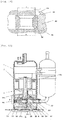
- Fig. 15 is a sectional view of an essential portion showing one example of the rotary compressor.
- the compressor mechanism 3 includes a cylinder 30 which forms a cylindrical inner space, a piston 32 disposed in the inner space of the cylinder 30, an end plate 34 of an upper bearing 34a which closes an upper end surface of the cylinder 30, an end plate 35 of a lower bearing 35a which closes a lower end surface of the cylinder 30, and a vane 33 which partitions an interior of a compression chamber 39 into a low pressure portion and a high pressure portion.
- the compression chamber 39 is made up of the inner space of the cylinder 30, the piston 32 and the end plates 34 and 35.
- the crankshaft 31 is supported by the upper bearing 34a and the lower bearing 35a.
- An eccentric core 31a is formed on the crankshaft 31.
- the eccentric core 31a is disposed between the end plates 34 and 35.
- the piston 32 is fitted over the eccentric core 31a.
- the vane 33 reciprocates in a slot provided in the cylinder 30. A tip end of the vane 33 comes into contact with an outer periphery of the piston 32 under pressure, and the vane 33 follows the eccentric rotation of the piston 32 and reciprocates, thereby partitioning the interior of the compression chamber 39 into the low pressure portion and the high pressure portion.
- An oil hole 41 is formed in the crankshaft 31 along its axis. Oil (lubricant oil) in the oil reservoir 6 is supplied to the oil hole 41.
- a wall of the crankshaft 31 is provided with oil supply holes 42 and 43 which are in communication with the oil hole 41.
- the oil supply hole 42 is formed in a wall corresponding to the upper bearing 34a and the oil supply hole 43 is formed in a wall corresponding to the lower bearing 35a.
- An oil groove (not shown) and an oil supply hole (not shown) which is in communication with the oil hole 41 are formed in the wall of the eccentric core 31a.
- a suction port 40 through which low pressure gas is sucked is formed in the cylinder 30.
- the suction port 40 is in communication with a low pressure portion (suction chamber) in the compression chamber 39.
- a discharge port 38 is formed in the upper bearing 34a and high pressure gas compressed in the compression chamber 39 is discharged through the discharge port 38.
- the discharge port 38 is in communication with the high pressure portion in the compression chamber 39.
- the discharge port 38 is formed as a hole which is circular as viewed from above, and the discharge port 38 penetrates the upper bearing 34a.
- the discharge port 38 is provided at its upper surface with a discharge valve 36.
- the discharge valve 36 is opened when it receives a pressure greater than a predetermined value.
- the discharge valve 36 is covered with a cup muffler 37.
- the low pressure portion (suction chamber) of the compression chamber 39 is gradually enlarged after sliding portions between the piston 32 and the cylinder 30 pass through the suction port 40, and the low pressure portion sucks gas from the suction port 40.
- the high pressure portion of the compression chamber 39 is gradually reduced in size, and when the high pressure portion is compressed to a value greater than a predetermined pressure, the discharge valve 36 opens and gas flows out from the discharge port 38. Gas which flows out from the discharge port 38 is discharged into the hermetic container 1 through the cup muffler 37.
- An upper space in the piston is formed by the eccentric core 31a of the crankshaft 31, the end plate 34 of the upper bearing 34a and an inner peripheral surface of the piston 32.
- a lower space in the piston is formed by the eccentric core 31a of the crankshaft 31, the end plate 35 of the lower bearing 35a and the inner peripheral surface of the piston 32.
- Oil in the oil hole 41 leaks from the oil supply hole 42 into the upper space in the piston, and oil in the oil hole 41 leaks from the oil supply hole 43 into the lower space in the piston. Pressures in the upper space and the lower space in the piston are always higher than a pressure in the compression chamber 39.
- a height of the cylinder 30 must be set slightly higher than the piston 32 so that the piston 32 can slide in the cylinder 30.
- a gap is generated between upper and lower end surfaces of the piston 32 and the end plates 34 and 35. Therefore, oil leaks from the upper space and the lower space in the piston into the compression chamber 39 through this gap. To enhance the efficiency, it is necessary to suppress this leakage and maintain the reliability.
- Figs. 10 to 14 show a state where the crankshaft 31 is omitted.
- Figs. 10 to 14 are schematic diagrams showing a relation of a gap between the piston 32 and the upper and lower end plates 34 and 35 (in the drawings, the vertical direction is exaggerated and an actual size is about a few tens of ⁇ m).
- upper and lower ends of the inner peripheral surface of the piston 32 are chamfered, and the chamfered portions of the upper and the lower ends are substantially the same.
- a first technique for enhancing the efficiency is to set a difference between upper and lower chamfered portions of the piston 32 to B-A>O as shown in Fig. 11 .
- gas leakage is generally proportional to cube of a gap, if upper and lower gaps of the piston 32 are unevenly distributed, an amount of gas leakage becomes greater as compared with a case where the upper and lower gaps of the piston 32 are evenly distributed. Hence, it is possible to suppress the amounts of gas and oil leaking into the suction chamber through the gaps in the upper and lower end surfaces of the piston 32, and efficiency is enhanced.
- a second technique for enhancing the efficiency is to reduce, in size, a gap between the piston 32 and the upper and lower end plates 34 and 35 to a few tens of ⁇ m as shown in Fig. 12 .
- Patent Document 1 Japanese Patent Application Laid-open No. H8-61276
- the document EP 1 640 614 is considered as being the closest prior art and discloses all the features of the preamble of claim 1.
- a first problem is that when a difference of the upper and lower chamfered portions is adjusted to cancel the weight of the piston 32 of its own as shown in Fig. 11 , a value of B-A becomes 0.1 or less and when productivity is to be enhanced, it is extremely difficult to manage sizes.
- a second problem is that when the upper and lower gaps of the piston 32 are reduced in size, it is necessary to increase both the upper and lower chamfered portions of the piston 32, but high pressure gas returns to the suction chamber and the efficiency is deteriorated if a sealing length between the inner surface of the piston 32 and the discharge port 38 is not secured as shown in the patent document 1 and thus, the upper chamfered portion can not be increased in size so much. After all, since only the lower chamfered portion having substantially the same size as that of the upper chamfered portion can be set, the reliability can not largely be enhanced.
- the present invention is accomplished to solve such problems, and it is an object of the invention to enhance the productivity, suppress the leakage through upper and lower end surfaces of a piston, suppress the wear and seizing of end plates, and enhance the reliability.
- the present invention provide a rotary compressor comprising a cylinder, an eccentric core of a shaft disposed in the cylinder, a piston fitted into the eccentric core, a vane which follows eccentric rotation of the piston and which reciprocates in a slot formed in the cylinder, and two end plates which close upper and lower end surfaces of the cylinder, characterized in that a second area surrounded by a lower inner surface angle portion which is formed on a lower end surface of the piston and the end plate which closes the lower end surface of the cylinder is set greater than a first area surrounded by an upper inner surface angle portion which is formed on an upper end surface of the piston and the end plate which closes the upper end surface of the cylinder, and an angle formed between the lower end surface of the piston and the lower inner surface angle portion is set smaller than an angle formed between the upper end surface of the piston and the upper inner surface angle portion.
- a second area surrounded by a lower inner surface angle portion which is formed on a lower end surface of the piston and the end plate which closes the lower end surface of the cylinder is set greater than a first area surrounded by an upper inner surface angle portion which is formed on an upper end surface of the piston and the end plate which closes the upper end surface of the cylinder, and an angle formed between the lower end surface of the piston and the lower inner surface angle portion is set smaller than an angle formed between the upper end surface of the piston and the upper inner surface angle portion.
- the upper inner surface angle portion is formed by chamfering, and the lower inner surface angle portion is formed by spot facing.
- the angle between the upper end surface of the piston and the upper inner surface angle portion is in a range of 132° to 138°.
- B-A is about 0.1 mm, but if the spot facing is formed only in the lower side of the piston, a range of tolerance can be increased to such a value that B-A becomes about 0.4 to 0.8 mm, and productivity is enhanced.
- the first area and the second area are set such that a weight of the piston of its own is canceled.
- the piston floats and the two gaps between the upper and lower end surfaces of the piston and the end plates are equalized. Since gas leakage is generally proportional to cube of a gap, if upper and lower gaps of the piston are unevenly distributed, an amount of gas leakage becomes greater as compared with a case where the upper and lower gaps of the piston are evenly distributed. Hence, since the amounts of gas and oil leaking into the suction chamber through the gaps in the upper and lower end surfaces of the piston are suppressed, the compression loss can be reduced, the same effect as that when the upper and lower gaps are reduced in size even if the upper and lower gaps are not reduced in size, and the reliability is further enhanced as compared with a case where the gaps are reduced in size and the efficiency is further enhanced.
- CO 2 which is a high pressure refrigerant is used as working fluid. According to this, even if CO 2 has a large pressure difference, a sliding loss and a leakage loss, it is possible to more effectively enhance the efficiency.
- a single refrigerant including hydrofluoroolefin having double bond between carbon and carbon as a basic component or a mixture refrigerant including this single refrigerant is used as working fluid.
- This refrigerant has such properties that the refrigerant can easily be decomposed at a high temperature, but it is possible to more effectively enhance the reliability of the compressor while suppressing high temperature decomposition of the refrigerant by reducing the leakage loss and the sliding loss.
- This refrigerant does not destroy ozone and has low global warming potential and this refrigerant can contribute to a configuration of an earth-friendly air-conditioning cycle.
- Fig. 1 is a vertical sectional view of a rotary compressor according to a first embodiment of the invention.
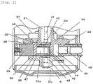
- Fig. 2 is an enlarged diagram of a compressor mechanism. Constituent members which are the same as those explained using Fig. 15 are designated with the same symbols, and explanation thereof will be omitted.
- An oil groove 45 and an oil supply hole 44 which is in communication with the oil hole 41 are formed in a wall of an eccentric core 31a of the crankshaft 31.
- the eccentric core 31a of the crankshaft 31, an end plate 34 of an upper bearing 34a and an inner peripheral surface of a piston 32 form an upper space 46 in the piston.
- the eccentric core 31a of the crankshaft 31, an end plate 35 of a lower bearing 35a and the inner peripheral surface of the piston 32 form a lower space 47 in the piston.
- Oil in the oil hole 41 leaks from the oil supply hole 42 into the upper space 46 in the piston, and oil in the oil hole 41 leaks from the oil supply hole 43 into the lower space 47 in the piston.
- Pressures in the upper space 46 in the piston and the lower space 47 in the piston are substantially always higher than a pressure in a compression chamber 39.
- a height of the cylinder 30 must be set slightly higher than that of the piston 32 so that the piston 32 can slide in the cylinder 30.
- a gap is generated between an end surface of the piston 32 and the end plate 34 of the upper bearing 34a, and a gap is generated between the end surface of the piston 32 and the end plate 35 of the lower bearing 35a.
- oil leaks from the upper space 46 and the lower space 47 into the compression chamber 39 in the piston through these gaps.
- a second area 32b surrounded by the end plate 35 and a lower inner surface angle portion formed on a lower end surface of the piston 32 is set greater than a first area 32a surrounded by the end plate 34 and an upper inner surface angle portion formed on an upper end surface of the piston 32.
- an angle D formed between a lower end surface of the piston 32 and the lower inner surface angle portion is set smaller than an angle C formed between an upper end surface of the piston 32 and the upper inner surface angle portion.
- the above-described configuration enhances efficiency and reliability.
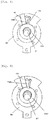
- Fig. 4 shows a distribution of a pressure applied to the piston 32 of the first embodiment.
- a high pressure is equally distributed to the upper side of the piston 32 on the inner surface side, and pressures from the high pressure to an intermediate pressure are straightly distributed to the upper side of the piston 32 on the end surface sides.
- a high pressure is equally distributed to a lower side of the piston 32, but pressures from an intermediate high pressure (lower than high pressure) to the intermediate pressure are straightly distributed to the lower side of the piston 32 on the side of the end surface sides. That is, since the angle D formed between the lower end surface of the piston 32 and the lower inner surface angle portion is set smaller than the angle C on the lower side of the piston 32, flow of oil is deteriorated, and a pressure drop is generated. Hence, even if a width B of the lower side of the piston 32 is increased as shown in Fig. 5 , such a large force is not generated upward.
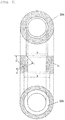
- Fig. 7 is a sectional view showing a piston of a rotary compressor according to a second embodiment of the invention. Since other structure is the same as that of the first embodiment, explanation thereof will be omitted.
- the second area 32b surrounded by the end plate 35 and the lower inner surface angle portion formed on the lower end surface of the piston 32 is set greater than the first area 32a surrounded by the end plate 34 and the upper inner surface angle portion formed on the upper end surface of the piston 32.
- the angle D formed between the lower end surface of the piston 32 and the lower inner surface angle portion is set smaller than the angle C formed between the upper end surface of the piston 32 and the upper inner surface angle portion.
- the upper inner surface angle portion is formed by chamfering the upper end surface and the upper inner surface of the piston 32, and the lower inner surface angle portion is formed by spot facing the lower end surface and the lower inner surface of the piston 32.
- the angle C between the upper end surface of the piston 32 and the upper inner surface angle portion is preferably in a range of 132° to 138°, and more preferably 135°.
- the angle D between the lower end surface of the piston 32 and the lower inner surface angle portion becomes 90°.
- the upper inner surface angle portion is formed by chamfering
- the lower inner surface angle portion is formed by spot facing. According to this, it is possible to visually determine or distinguish the upper side and the lower side from each other at the time of an assembling operation, and it is possible to reduce the efficiency deterioration and loss of cost caused by error between the upper side and the lower side of the piston 32.
- B-A is about 0.1 mm
- B-A is about 0.1 mm
- a range of tolerance can be increased to such a value that B-A becomes about 0.4 to 0.8 mm, and productivity is enhanced.
- Fig. 8 shows a rotary compressor having a configuration different from that of the first embodiment of the invention.
- the same configurations as those of the first embodiment are designated with the same symbols, and explanation thereof will be omitted.
- the rotary compressor shown in Fig. 8 includes a vane 133 which is coupled to an outer periphery of a piston 132 in a projecting form and which distinguishes a low pressure side and a high pressure side of the compression chamber 39 from each other, and a rocking bush 130 which supports the vane 133 such that it can rock and move forward and backward.
- Fig. 9 shows a rotary compressor having another configuration.
- the same configurations as those of the first embodiment are designated with the same symbols, and explanation thereof will be omitted.
- the rotary compressor shown in Fig. 9 includes a piston 232 and a vane 233 whose tip end is rockably connected to the piston 232.
- CO 2 is used as working fluid, even if a pressure difference is large and influence of a leakage loss and a sliding loss are large, it is possible to reduce the leakage of fluid at the upper and lower end surfaces of the piston 32, and a force strongly pressing the piston 32 downward can be avoided and thus, it is possible to more effectively enhance the efficiency.
- mixture refrigerant in which tetrafluoropropene (HFO1234yf or HFO1234ze) or trifluoropropene (HFO1243zf) is used as hydrofluoroolefin and difluoromethane (HFC32) is used as hydrofluorocarbon.
- mixture refrigerant in which tetrafluoropropene (HFO1234yf or HFO1234ze) or trifluoropropene (HFO1243zf) is as hydrofluoroolefin and pentafluoroethane (HFC125) is used as hydrofluorocarbon.
- mixture refrigerant including three components in which tetrafluoropropene (HFO1234yf or HFO1234ze) or trifluoropropene (HFO1243zf) is used as hydrofluoroolefin and pentafluoroethane (HFC125) or difluoromethane (HFC32) is used as hydrofluorocarbon.
- HFO1234yf or HFO1234ze tetrafluoropropene
- HFO1243zf trifluoropropene
- HFC125 pentafluoroethane
- HFC32 difluoromethane
- the rotary compressor may includes a plurality of cylinders.
- the rotary compressor of the invention it is possible to suppress deterioration of reliability such as wear and seizing, reduce the leakage loss and sliding loss at the same time, and enhance the efficiency of the compressor.
- the invention can be applied to an air conditioner and a heat pump hot water supply apparatus using natural refrigerant CO 2 in addition to an air conditioner compressor using HFC-based refrigerant or HCFC-based refrigerant.
Landscapes
- Engineering & Computer Science (AREA)
- Mechanical Engineering (AREA)
- General Engineering & Computer Science (AREA)
- Applications Or Details Of Rotary Compressors (AREA)
Claims (6)
- Rotationskompressor, enthaltend einen Zylinder (30), einen exzentrischen Kern (31a) einer in dem Zylinder (30) angeordneten Welle (31), einen in den exzentrischen Kern (31a) eingesetzten Kolben (32), einen Trennschieber (133), der einer exzentrischen Rotation des Kolbens (32) folgt und der sich in einem in dem Zylinder (30) ausgebildeten Schlitz hin- und herbewegt, und zwei Endplatten (34, 35), die die oberen und unteren Endflächen des Zylinders (30) verschließen, wobei ein unterer Innenflächenwinkelabschnitt (32d), dessen äußerer Umfangskreis einen Durchmesser B besitzt, auf einem inneren Umfangsendabschnitt einer unteren Endfläche des Kolbens (32) ausgebildet ist, wobei ein oberer Innenflächenwinkelabschnitt (32c), dessen äußerer Umfangskreis einen Durchmesser A besitzt, auf einem inneren Umfangsendabschnitt einer oberen Endfläche des Kolbens (32) ausgebildet ist, wobei ein zweiter Bereich (32b), der von dem äußeren Umfangskreis des Durchmessers B umgeben ist, der der Endplatte (35) gegenüber liegt, die die untere Endfläche des Zylinders (30) verschließt, größer eingestellt ist als ein erster Bereich (32a), der von dem äußeren Umfangskreis des Durchmessers A umgeben ist, der der Endplatte (34) gegenüber liegt, die die obere Endfläche des Zylinders (30) verschließt,
dadurch gekennzeichnet, dass ein Winkel (D), der in Richtung zwischen der unteren Endfläche des Kolbens (32) und dem unteren Innenflächenwinkelabschnitt (32d) ausgebildet ist, kleiner eingestellt ist als ein Winkel (C), der zwischen der oberen Endfläche des Kolbens (32) und dem oberen Innenflächenwinkelabschnitt (32c) gebildet ist. - Rotationskompressor nach Anspruch 1,
dadurch gekennzeichnet, dass der obere Innenflächenwinkelabschnitt durch Abschrägen, und der untere Innenflächenwinkelabschnitt durch Plansenken gebildet ist. - Rotationskompressor nach Anspruch 2,
dadurch gekennzeichnet, dass der Winkel (C) zwischen der oberen Endfläche des Kolbens (32) und dem oberen Innenflächenwinkelabschnitt in einem Bereich von 132° bis 138° liegt. - Rotationskompressor nach einem der Ansprüche 1 bis 3,
dadurch gekennzeichnet, dass der erste Bereich und der zweite Bereich so eingestellt sind, dass ein Eigengewicht des Kolbens (32) aufgehoben wird. - Rotationskompressor nach einem der Ansprüche 1 bis 4,
dadurch gekennzeichnet, dass CO2, das ein Hochdruckkältemittel ist, als Arbeitsfluid verwendet wird. - Rotationskompressor nach einem der Ansprüche 1 bis 5,
dadurch gekennzeichnet, dass ein einzelnes Kältemittel, das Hydrofluoroolefin mit Doppelbindung zwischen Kohlenstoff und Kohlenstoff als Basiskomponente enthält, oder ein Mischkältemittel, das dieses einzelne Kältemittel enthält, als Arbeitsfluid verwendet wird.
Applications Claiming Priority (2)
| Application Number | Priority Date | Filing Date | Title |
|---|---|---|---|
| JP2010151756 | 2010-07-02 | ||
| PCT/JP2011/003773 WO2012001989A1 (ja) | 2010-07-02 | 2011-07-01 | 回転式圧縮機 |
Publications (3)
| Publication Number | Publication Date |
|---|---|
| EP2589810A1 EP2589810A1 (de) | 2013-05-08 |
| EP2589810A4 EP2589810A4 (de) | 2016-05-18 |
| EP2589810B1 true EP2589810B1 (de) | 2018-05-02 |
Family
ID=45401727
Family Applications (1)
| Application Number | Title | Priority Date | Filing Date |
|---|---|---|---|
| EP11800459.7A Active EP2589810B1 (de) | 2010-07-02 | 2011-07-01 | Rotationsverdichter |
Country Status (4)
| Country | Link |
|---|---|
| EP (1) | EP2589810B1 (de) |
| JP (1) | JP4928016B2 (de) |
| CN (1) | CN102483066B (de) |
| WO (1) | WO2012001989A1 (de) |
Families Citing this family (3)
| Publication number | Priority date | Publication date | Assignee | Title |
|---|---|---|---|---|
| CN113565761B (zh) * | 2021-08-30 | 2023-04-25 | 广东美芝制冷设备有限公司 | 活塞、旋转式压缩机及制冷设备 |
| CN113653642A (zh) * | 2021-09-26 | 2021-11-16 | 广东美芝制冷设备有限公司 | 泵体组件、旋转式压缩机以及制冷设备 |
| JP7358674B1 (ja) * | 2023-06-07 | 2023-10-10 | 日立ジョンソンコントロールズ空調株式会社 | 圧縮機および空気調和装置 |
Family Cites Families (7)
| Publication number | Priority date | Publication date | Assignee | Title |
|---|---|---|---|---|
| JPH0861276A (ja) | 1994-08-12 | 1996-03-08 | Toshiba Corp | ロータリコンプレッサ |
| JP3702686B2 (ja) * | 1999-01-21 | 2005-10-05 | ダイキン工業株式会社 | ロータリ圧縮機 |
| JP2004225578A (ja) * | 2003-01-21 | 2004-08-12 | Matsushita Electric Ind Co Ltd | ロータリ圧縮機 |
| JP2005002832A (ja) * | 2003-06-10 | 2005-01-06 | Daikin Ind Ltd | ロータリー流体機械 |
| JP2006177227A (ja) * | 2004-12-22 | 2006-07-06 | Hitachi Home & Life Solutions Inc | ロータリ式2段圧縮機 |
| JP2010031733A (ja) * | 2008-07-29 | 2010-02-12 | Panasonic Corp | ロータリ圧縮機 |
| CN201301810Y (zh) * | 2008-11-06 | 2009-09-02 | 松下·万宝(广州)压缩机有限公司 | 压缩机 |
-
2011
- 2011-07-01 EP EP11800459.7A patent/EP2589810B1/de active Active
- 2011-07-01 WO PCT/JP2011/003773 patent/WO2012001989A1/ja not_active Ceased
- 2011-07-01 CN CN201180003212.XA patent/CN102483066B/zh active Active
- 2011-07-01 JP JP2011551339A patent/JP4928016B2/ja active Active
Non-Patent Citations (1)
| Title |
|---|
| None * |
Also Published As
| Publication number | Publication date |
|---|---|
| WO2012001989A1 (ja) | 2012-01-05 |
| JP4928016B2 (ja) | 2012-05-09 |
| JPWO2012001989A1 (ja) | 2013-08-22 |
| EP2589810A4 (de) | 2016-05-18 |
| CN102483066B (zh) | 2014-08-06 |
| CN102483066A (zh) | 2012-05-30 |
| EP2589810A1 (de) | 2013-05-08 |
Similar Documents
| Publication | Publication Date | Title |
|---|---|---|
| EP2770212B1 (de) | Rotationskompressor mit zwei zylindern | |
| US9482231B2 (en) | Rotary compressor having an oil groove in an inner peripheral surface of a bearing | |
| US8985978B2 (en) | Scroll compressor with bypass holes | |
| US9157437B2 (en) | Rotary compressor with oiling mechanism | |
| JP6787480B2 (ja) | ロータリ圧縮機 | |
| JP2010031785A (ja) | 冷媒圧縮機 | |
| EP2418386B1 (de) | Rotationsverdichter | |
| WO2007000854A1 (ja) | 流体機械及び冷凍サイクル装置 | |
| CN103827499B (zh) | 压缩机 | |
| EP2589810A1 (de) | Rotationsverdichter | |
| JP2011252475A (ja) | 回転式圧縮機 | |
| JP5540557B2 (ja) | ロータリ圧縮機 | |
| US20130189080A1 (en) | Rotary compressor | |
| WO2013080519A1 (ja) | ロータリ圧縮機 | |
| JP2012237197A (ja) | ロータリ圧縮機 | |
| JP2012017690A (ja) | 回転式圧縮機 | |
| JP6758422B2 (ja) | 回転圧縮機 | |
| EP2857688B1 (de) | Rotationsverdichter | |
| JP6176577B2 (ja) | 圧縮機 | |
| JP5927407B2 (ja) | ロータリ圧縮機 | |
| JP2011157911A (ja) | ロータリ圧縮機 | |
| JP2006291763A (ja) | スクロール圧縮機 | |
| JP2008002423A (ja) | スクロール圧縮機 | |
| WO2013084486A1 (ja) | スクロール圧縮機 |
Legal Events
| Date | Code | Title | Description |
|---|---|---|---|
| PUAI | Public reference made under article 153(3) epc to a published international application that has entered the european phase |
Free format text: ORIGINAL CODE: 0009012 |
|
| 17P | Request for examination filed |
Effective date: 20120207 |
|
| AK | Designated contracting states |
Kind code of ref document: A1 Designated state(s): AL AT BE BG CH CY CZ DE DK EE ES FI FR GB GR HR HU IE IS IT LI LT LU LV MC MK MT NL NO PL PT RO RS SE SI SK SM TR |
|
| DAX | Request for extension of the european patent (deleted) | ||
| RA4 | Supplementary search report drawn up and despatched (corrected) |
Effective date: 20160419 |
|
| RIC1 | Information provided on ipc code assigned before grant |
Ipc: F04C 18/32 20060101ALI20160413BHEP Ipc: F04C 18/356 20060101ALI20160413BHEP Ipc: F04C 18/324 20060101ALI20160413BHEP Ipc: F04C 29/00 20060101AFI20160413BHEP |
|
| GRAP | Despatch of communication of intention to grant a patent |
Free format text: ORIGINAL CODE: EPIDOSNIGR1 |
|
| STAA | Information on the status of an ep patent application or granted ep patent |
Free format text: STATUS: GRANT OF PATENT IS INTENDED |
|
| INTG | Intention to grant announced |
Effective date: 20171110 |
|
| RIN1 | Information on inventor provided before grant (corrected) |
Inventor name: SAKIMOTO, TAKAMASA Inventor name: IIDA, NOBORU Inventor name: FUNAKOSHI, DAISUKE Inventor name: SUGIURA, HIROSHI |
|
| GRAS | Grant fee paid |
Free format text: ORIGINAL CODE: EPIDOSNIGR3 |
|
| GRAA | (expected) grant |
Free format text: ORIGINAL CODE: 0009210 |
|
| STAA | Information on the status of an ep patent application or granted ep patent |
Free format text: STATUS: THE PATENT HAS BEEN GRANTED |
|
| AK | Designated contracting states |
Kind code of ref document: B1 Designated state(s): AL AT BE BG CH CY CZ DE DK EE ES FI FR GB GR HR HU IE IS IT LI LT LU LV MC MK MT NL NO PL PT RO RS SE SI SK SM TR |
|
| REG | Reference to a national code |
Ref country code: GB Ref legal event code: FG4D |
|
| REG | Reference to a national code |
Ref country code: CH Ref legal event code: EP Ref country code: AT Ref legal event code: REF Ref document number: 995559 Country of ref document: AT Kind code of ref document: T Effective date: 20180515 |
|
| REG | Reference to a national code |
Ref country code: DE Ref legal event code: R096 Ref document number: 602011048092 Country of ref document: DE Ref country code: IE Ref legal event code: FG4D |
|
| REG | Reference to a national code |
Ref country code: NL Ref legal event code: MP Effective date: 20180502 |
|
| REG | Reference to a national code |
Ref country code: LT Ref legal event code: MG4D |
|
| PG25 | Lapsed in a contracting state [announced via postgrant information from national office to epo] |
Ref country code: SE Free format text: LAPSE BECAUSE OF FAILURE TO SUBMIT A TRANSLATION OF THE DESCRIPTION OR TO PAY THE FEE WITHIN THE PRESCRIBED TIME-LIMIT Effective date: 20180502 Ref country code: LT Free format text: LAPSE BECAUSE OF FAILURE TO SUBMIT A TRANSLATION OF THE DESCRIPTION OR TO PAY THE FEE WITHIN THE PRESCRIBED TIME-LIMIT Effective date: 20180502 Ref country code: ES Free format text: LAPSE BECAUSE OF FAILURE TO SUBMIT A TRANSLATION OF THE DESCRIPTION OR TO PAY THE FEE WITHIN THE PRESCRIBED TIME-LIMIT Effective date: 20180502 Ref country code: BG Free format text: LAPSE BECAUSE OF FAILURE TO SUBMIT A TRANSLATION OF THE DESCRIPTION OR TO PAY THE FEE WITHIN THE PRESCRIBED TIME-LIMIT Effective date: 20180802 Ref country code: FI Free format text: LAPSE BECAUSE OF FAILURE TO SUBMIT A TRANSLATION OF THE DESCRIPTION OR TO PAY THE FEE WITHIN THE PRESCRIBED TIME-LIMIT Effective date: 20180502 Ref country code: NO Free format text: LAPSE BECAUSE OF FAILURE TO SUBMIT A TRANSLATION OF THE DESCRIPTION OR TO PAY THE FEE WITHIN THE PRESCRIBED TIME-LIMIT Effective date: 20180802 |
|
| PG25 | Lapsed in a contracting state [announced via postgrant information from national office to epo] |
Ref country code: GR Free format text: LAPSE BECAUSE OF FAILURE TO SUBMIT A TRANSLATION OF THE DESCRIPTION OR TO PAY THE FEE WITHIN THE PRESCRIBED TIME-LIMIT Effective date: 20180803 Ref country code: RS Free format text: LAPSE BECAUSE OF FAILURE TO SUBMIT A TRANSLATION OF THE DESCRIPTION OR TO PAY THE FEE WITHIN THE PRESCRIBED TIME-LIMIT Effective date: 20180502 Ref country code: LV Free format text: LAPSE BECAUSE OF FAILURE TO SUBMIT A TRANSLATION OF THE DESCRIPTION OR TO PAY THE FEE WITHIN THE PRESCRIBED TIME-LIMIT Effective date: 20180502 Ref country code: NL Free format text: LAPSE BECAUSE OF FAILURE TO SUBMIT A TRANSLATION OF THE DESCRIPTION OR TO PAY THE FEE WITHIN THE PRESCRIBED TIME-LIMIT Effective date: 20180502 Ref country code: HR Free format text: LAPSE BECAUSE OF FAILURE TO SUBMIT A TRANSLATION OF THE DESCRIPTION OR TO PAY THE FEE WITHIN THE PRESCRIBED TIME-LIMIT Effective date: 20180502 |
|
| REG | Reference to a national code |
Ref country code: AT Ref legal event code: MK05 Ref document number: 995559 Country of ref document: AT Kind code of ref document: T Effective date: 20180502 |
|
| PG25 | Lapsed in a contracting state [announced via postgrant information from national office to epo] |
Ref country code: SK Free format text: LAPSE BECAUSE OF FAILURE TO SUBMIT A TRANSLATION OF THE DESCRIPTION OR TO PAY THE FEE WITHIN THE PRESCRIBED TIME-LIMIT Effective date: 20180502 Ref country code: EE Free format text: LAPSE BECAUSE OF FAILURE TO SUBMIT A TRANSLATION OF THE DESCRIPTION OR TO PAY THE FEE WITHIN THE PRESCRIBED TIME-LIMIT Effective date: 20180502 Ref country code: PL Free format text: LAPSE BECAUSE OF FAILURE TO SUBMIT A TRANSLATION OF THE DESCRIPTION OR TO PAY THE FEE WITHIN THE PRESCRIBED TIME-LIMIT Effective date: 20180502 Ref country code: DK Free format text: LAPSE BECAUSE OF FAILURE TO SUBMIT A TRANSLATION OF THE DESCRIPTION OR TO PAY THE FEE WITHIN THE PRESCRIBED TIME-LIMIT Effective date: 20180502 Ref country code: AT Free format text: LAPSE BECAUSE OF FAILURE TO SUBMIT A TRANSLATION OF THE DESCRIPTION OR TO PAY THE FEE WITHIN THE PRESCRIBED TIME-LIMIT Effective date: 20180502 Ref country code: CZ Free format text: LAPSE BECAUSE OF FAILURE TO SUBMIT A TRANSLATION OF THE DESCRIPTION OR TO PAY THE FEE WITHIN THE PRESCRIBED TIME-LIMIT Effective date: 20180502 Ref country code: RO Free format text: LAPSE BECAUSE OF FAILURE TO SUBMIT A TRANSLATION OF THE DESCRIPTION OR TO PAY THE FEE WITHIN THE PRESCRIBED TIME-LIMIT Effective date: 20180502 |
|
| REG | Reference to a national code |
Ref country code: DE Ref legal event code: R097 Ref document number: 602011048092 Country of ref document: DE |
|
| PG25 | Lapsed in a contracting state [announced via postgrant information from national office to epo] |
Ref country code: IT Free format text: LAPSE BECAUSE OF FAILURE TO SUBMIT A TRANSLATION OF THE DESCRIPTION OR TO PAY THE FEE WITHIN THE PRESCRIBED TIME-LIMIT Effective date: 20180502 Ref country code: SM Free format text: LAPSE BECAUSE OF FAILURE TO SUBMIT A TRANSLATION OF THE DESCRIPTION OR TO PAY THE FEE WITHIN THE PRESCRIBED TIME-LIMIT Effective date: 20180502 |
|
| REG | Reference to a national code |
Ref country code: CH Ref legal event code: PL |
|
| PLBE | No opposition filed within time limit |
Free format text: ORIGINAL CODE: 0009261 |
|
| STAA | Information on the status of an ep patent application or granted ep patent |
Free format text: STATUS: NO OPPOSITION FILED WITHIN TIME LIMIT |
|
| PG25 | Lapsed in a contracting state [announced via postgrant information from national office to epo] |
Ref country code: MC Free format text: LAPSE BECAUSE OF FAILURE TO SUBMIT A TRANSLATION OF THE DESCRIPTION OR TO PAY THE FEE WITHIN THE PRESCRIBED TIME-LIMIT Effective date: 20180502 Ref country code: LU Free format text: LAPSE BECAUSE OF NON-PAYMENT OF DUE FEES Effective date: 20180701 |
|
| REG | Reference to a national code |
Ref country code: BE Ref legal event code: MM Effective date: 20180731 |
|
| 26N | No opposition filed |
Effective date: 20190205 |
|
| REG | Reference to a national code |
Ref country code: IE Ref legal event code: MM4A |
|
| GBPC | Gb: european patent ceased through non-payment of renewal fee |
Effective date: 20180802 |
|
| PG25 | Lapsed in a contracting state [announced via postgrant information from national office to epo] |
Ref country code: IE Free format text: LAPSE BECAUSE OF NON-PAYMENT OF DUE FEES Effective date: 20180701 Ref country code: CH Free format text: LAPSE BECAUSE OF NON-PAYMENT OF DUE FEES Effective date: 20180731 Ref country code: FR Free format text: LAPSE BECAUSE OF NON-PAYMENT OF DUE FEES Effective date: 20180702 Ref country code: LI Free format text: LAPSE BECAUSE OF NON-PAYMENT OF DUE FEES Effective date: 20180731 |
|
| PG25 | Lapsed in a contracting state [announced via postgrant information from national office to epo] |
Ref country code: BE Free format text: LAPSE BECAUSE OF NON-PAYMENT OF DUE FEES Effective date: 20180731 Ref country code: SI Free format text: LAPSE BECAUSE OF FAILURE TO SUBMIT A TRANSLATION OF THE DESCRIPTION OR TO PAY THE FEE WITHIN THE PRESCRIBED TIME-LIMIT Effective date: 20180502 |
|
| PG25 | Lapsed in a contracting state [announced via postgrant information from national office to epo] |
Ref country code: GB Free format text: LAPSE BECAUSE OF NON-PAYMENT OF DUE FEES Effective date: 20180802 |
|
| PG25 | Lapsed in a contracting state [announced via postgrant information from national office to epo] |
Ref country code: AL Free format text: LAPSE BECAUSE OF FAILURE TO SUBMIT A TRANSLATION OF THE DESCRIPTION OR TO PAY THE FEE WITHIN THE PRESCRIBED TIME-LIMIT Effective date: 20180502 |
|
| PG25 | Lapsed in a contracting state [announced via postgrant information from national office to epo] |
Ref country code: MT Free format text: LAPSE BECAUSE OF NON-PAYMENT OF DUE FEES Effective date: 20180701 |
|
| PG25 | Lapsed in a contracting state [announced via postgrant information from national office to epo] |
Ref country code: TR Free format text: LAPSE BECAUSE OF FAILURE TO SUBMIT A TRANSLATION OF THE DESCRIPTION OR TO PAY THE FEE WITHIN THE PRESCRIBED TIME-LIMIT Effective date: 20180502 |
|
| PG25 | Lapsed in a contracting state [announced via postgrant information from national office to epo] |
Ref country code: HU Free format text: LAPSE BECAUSE OF FAILURE TO SUBMIT A TRANSLATION OF THE DESCRIPTION OR TO PAY THE FEE WITHIN THE PRESCRIBED TIME-LIMIT; INVALID AB INITIO Effective date: 20110701 Ref country code: PT Free format text: LAPSE BECAUSE OF FAILURE TO SUBMIT A TRANSLATION OF THE DESCRIPTION OR TO PAY THE FEE WITHIN THE PRESCRIBED TIME-LIMIT Effective date: 20180502 |
|
| PG25 | Lapsed in a contracting state [announced via postgrant information from national office to epo] |
Ref country code: CY Free format text: LAPSE BECAUSE OF FAILURE TO SUBMIT A TRANSLATION OF THE DESCRIPTION OR TO PAY THE FEE WITHIN THE PRESCRIBED TIME-LIMIT Effective date: 20180502 Ref country code: MK Free format text: LAPSE BECAUSE OF NON-PAYMENT OF DUE FEES Effective date: 20180502 |
|
| PG25 | Lapsed in a contracting state [announced via postgrant information from national office to epo] |
Ref country code: IS Free format text: LAPSE BECAUSE OF FAILURE TO SUBMIT A TRANSLATION OF THE DESCRIPTION OR TO PAY THE FEE WITHIN THE PRESCRIBED TIME-LIMIT Effective date: 20180902 |
|
| PGFP | Annual fee paid to national office [announced via postgrant information from national office to epo] |
Ref country code: DE Payment date: 20250722 Year of fee payment: 15 |